JP2014105902A - Oil recovery device - Google Patents
Oil recovery device Download PDFInfo
- Publication number
- JP2014105902A JP2014105902A JP2012257849A JP2012257849A JP2014105902A JP 2014105902 A JP2014105902 A JP 2014105902A JP 2012257849 A JP2012257849 A JP 2012257849A JP 2012257849 A JP2012257849 A JP 2012257849A JP 2014105902 A JP2014105902 A JP 2014105902A
- Authority
- JP
- Japan
- Prior art keywords
- oil
- oil recovery
- slider crank
- crank mechanism
- component
- Prior art date
- Legal status (The legal status is an assumption and is not a legal conclusion. Google has not performed a legal analysis and makes no representation as to the accuracy of the status listed.)
- Granted
Links
- 238000011084 recovery Methods 0.000 title claims abstract description 27
- 230000007246 mechanism Effects 0.000 claims abstract description 28
- 229910000831 Steel Inorganic materials 0.000 claims abstract description 15
- 239000010959 steel Substances 0.000 claims abstract description 15
- 230000001133 acceleration Effects 0.000 claims description 5
- 230000004308 accommodation Effects 0.000 abstract 2
- 238000012423 maintenance Methods 0.000 description 3
- 238000007796 conventional method Methods 0.000 description 2
- 230000003028 elevating effect Effects 0.000 description 2
- 238000000034 method Methods 0.000 description 2
- 238000010791 quenching Methods 0.000 description 2
- 230000000171 quenching effect Effects 0.000 description 2
- 238000000926 separation method Methods 0.000 description 2
- 238000003860 storage Methods 0.000 description 2
- 239000006096 absorbing agent Substances 0.000 description 1
- 238000005520 cutting process Methods 0.000 description 1
- 238000010586 diagram Methods 0.000 description 1
- 230000000694 effects Effects 0.000 description 1
- 235000013305 food Nutrition 0.000 description 1
- 238000012986 modification Methods 0.000 description 1
- 230000004048 modification Effects 0.000 description 1
- NJPPVKZQTLUDBO-UHFFFAOYSA-N novaluron Chemical compound C1=C(Cl)C(OC(F)(F)C(OC(F)(F)F)F)=CC=C1NC(=O)NC(=O)C1=C(F)C=CC=C1F NJPPVKZQTLUDBO-UHFFFAOYSA-N 0.000 description 1
- 238000003825 pressing Methods 0.000 description 1
- 230000035939 shock Effects 0.000 description 1
- 235000013311 vegetables Nutrition 0.000 description 1
- 238000005406 washing Methods 0.000 description 1
Images



Landscapes
- Drying Of Solid Materials (AREA)
Abstract
Description
この発明は油回収装置に関し、特に、油の付着した小さな機械部品から効率よく油を回収できる油回収装置に関する。 The present invention relates to an oil recovery apparatus, and more particularly, to an oil recovery apparatus that can efficiently recover oil from small mechanical parts to which oil is adhered.
従来の、水切りや油きりをする方法としては、次のようなものがあった。たとえば、食品フライヤーでのてんぷらの油きり、機械切削チップの脱油、野菜水洗後の水切りなどは、主として遠心式分離機に投入して高速回転を与える方式を採用していた。また、風圧や吸引ブロワーによる空気分離方式もあった。 Conventional methods for draining and oiling have been as follows. For example, for tempura draining of food fryer, de-oiling of machine cutting chips, draining after washing with vegetables, etc., a method of mainly feeding into a centrifugal separator to give high speed rotation has been adopted. There were also air separation systems using wind pressure and suction blowers.
従来の水切りや油きりをする方法としては上記のようなものがあった。遠心式分離機に投入して高速回転を与える方式では、装置が大掛かりになるとともに、品物投入と搬出の工程が必要となるという問題があった。 Conventional methods for draining and oiling have been as described above. In the system in which the centrifugal separator is charged to give high-speed rotation, there is a problem that the apparatus becomes large and the steps of loading and unloading the product are required.
また、風圧や吸引ブロワーによる空気分離方式は、品物が多層に重なりのある状態では効果が薄い、という問題があった。 In addition, the air separation method using the wind pressure or the suction blower has a problem that the effect is weak in a state where the articles are stacked in multiple layers.
この発明は上記のような問題点を解消するためになされたもので、小さな機械部品等から効率よく油切りが可能な油回収装置を提供することを目的とする。 The present invention has been made to solve the above-described problems, and an object of the present invention is to provide an oil recovery apparatus that can efficiently drain oil from small mechanical parts and the like.
この発明に係る油回収装置は、水平の載置面を有し、油を有する部品を収容する部品収容器と、部品収容器を上下方向に移動させるスライダークランク機構とを含む。 The oil recovery apparatus according to the present invention includes a component container that has a horizontal placement surface and that accommodates components having oil, and a slider crank mechanism that moves the component container in the vertical direction.
好ましくは、スライダークランク機構は重力加速度が1を越えないように部品収容器を上下方向に移動する。 Preferably, the slider crank mechanism moves the component container in the vertical direction so that the gravitational acceleration does not exceed 1.
さらに好ましくは、部品収容器は軸受用の鋼球を収容する。 More preferably, the component container accommodates a steel ball for bearing.
スライダークランク機構は1個の部品収容器について2個設けられてもよい。 Two slider crank mechanisms may be provided for one component container.
部品を収容する部品収容器をスライダークランク機構で上下動させることにより部品からの油切を行うようにしたため、簡単な構成で、小さな機械部品から効率よく油を回収できる油回収装置を提供できる。 Since the component container that accommodates the component is moved up and down by the slider crank mechanism, the oil is drained from the component. Therefore, it is possible to provide an oil recovery device that can efficiently recover oil from small mechanical components with a simple configuration.
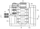
以下、この発明の実施の形態について図面を参照して説明する。図1は、この発明の一実施の形態に係る油回収装置の要部を示す正面図である。図2は図1において矢印II−IIで示す部分の矢視図(平面図)であり、図3は図1において矢印III−IIIで示す部分の矢視図である。ここでは、油回収装置10が軸受用の鋼球を油焼き入れした後に、鋼球から油を回収する場合について説明する。
Embodiments of the present invention will be described below with reference to the drawings. FIG. 1 is a front view showing a main part of an oil recovery apparatus according to an embodiment of the present invention. 2 is an arrow view (plan view) of the portion indicated by arrow II-II in FIG. 1, and FIG. 3 is an arrow view of the portion indicated by arrow III-III in FIG. Here, the case where oil is recovered from a steel ball after the
図1〜3を参照して、油回収装置10はスライダークランク機構20と、スライダークランク機構20に接続された容器保持部30と、容器保持部30に保持された部品収容器35と、部品収容器35の下面に設けられ、鋼球から油を回収するための油回収パン36とを含む。なお、スライダークランク機構20、容器保持部30、部品収容器35、および油回収パン36は架台40に保持されている。
1-3, the
部品収容器35は油焼き入れ後の軸受用の鋼球を含む6段のケース35a〜35fからなる。6段のケース35a〜35fは相互に縦方向に一体化されている。それぞれのケース35a〜35fは底面を有する直方体状であり、底面に複数の鋼球が載置されている。容器保持部30は、リニアガイド33a,33b(図3参照)に沿って、垂直方向に上下動する。
The
容器保持部30はスライダークランク機構20の棒部材28に接続されたリンク25の他端にピン31aを介して接続された昇降支持部31と、部品収容器35を搬入するためのローラコンベヤ34と、ローラコンベヤ34を含んで、部品収容器35の周囲を囲むように設けられた収容枠体38を含む。収容枠体38は、直方体を構成する12の辺39を有し、部品収容器35をその上端部で覆うワーク押え部材37を有する。昇降支持部31に一体的に接続された収納枠体36がスライダークランク機構20によってリニアガイド33a,33bに沿って上下動される。
The
なお、図中、二点鎖線で示したのは容器保持部30が上端および下端に移動された場合を示す。また、図3において、リンク等の図示は省略している。
In addition, what was shown with the dashed-two dotted line in the figure shows the case where the container holding |
架台40はスライダークランク機構20を駆動するモータ45、および、後に説明する棒部材28の一端を回動自在に保持する軸受27を支持する軸受支持台27aを支持するモータ支持架台41eを含む。
The
ここでは、油焼き入れ後の軸受用の鋼球を含む6段のケース35a〜35fが容器保持部35を介してスライダークランク機構20によって上下動され、それによって鋼球から油が滴下し、滴下した油が油回収パン36によって回収される。
Here, the six-stage cases 35a to 35f including the steel balls for bearing after oil quenching are moved up and down by the
次に、スライダークランク機構20について説明する。図4はスライダークランク機構20の全体構成を示す模式図である。図4を参照して、スライダークランク機構20は、モータ45(図2参照)の回転軸点26を中心として回転される円盤21を含む。円盤21はその外周部にピン22を有する。
Next, the
一方、棒部材28は、軸受27によって、その一端に設けられた支点23を中心として上下動可能である。棒部材28にはその他方端側に長孔24を有し、この長孔24にピン22が係合する。その結果、モータ45によって軸26を中心として円盤21が図中Aで示す方向に回転すると、それに応じてピン22は長孔24に沿ってスライドし、棒部材28は支点23を中心として軸26を中心に図中Cで示すように上下動する。このとき、図中矢印Bで示す範囲ではリンク25の上下動が早くなる。
On the other hand, the
なお、ピン22が係合する棒部材28の長孔24の位置、円盤21に設けられたピン22との位置関係はモータ45の回転に応じて、棒部材28に接続されたリンク25の上下動が適切に油を切るように選ばれている。
Note that the position of the
なお、ここでは、次の条件で油の回収を行うものとする。 Here, oil is recovered under the following conditions.
軸受の鋼球の径は0.8mm〜4mmであり、これがケースに収容され、そのケースを複数重ねて処理する。 The diameter of the steel ball of the bearing is 0.8 mm to 4 mm, and this is accommodated in a case, and a plurality of cases are processed in a stacked manner.
個々のケースは772mm長さ×450mm幅×300mm高さの直方体状であり、これが6段セットされたものから油を回収する。ここで、全重量はケース込みで160kgである。また、油の回収時間は1ロット当たり15分とする。 Each case has a rectangular parallelepiped shape of 772 mm length × 450 mm width × 300 mm height, and oil is recovered from a set of 6 stages. Here, the total weight is 160 kg including the case. The oil recovery time is 15 minutes per lot.
油の回収目標値は6段ケースで約2kgの油の付着を最低限半分回収するものとする。 The oil recovery target value shall be a minimum of half of about 2 kg of oil adhering in a 6-stage case.
次に、スライダークランク機構20の仕様について説明する。図5(A)〜(C)は、それぞれ、スライダークランク機構20を構成する円盤21に設けられたピン22の回転角度ごとの上下位置H(cm)(A)と、速度V(m/s)(B)と、重力加速度G(C)を示すグラフであり、表1はその内容を示すデータである。
Next, the specification of the

ここでは、スライダークランク機構20は次の条件のもとで駆動される。
Here, the
棒部材28が水平位置にあるときを0°とする(図4参照)。なお、図5においては、回転角度の1が0°に対応し、37が360°に対応する。
When the
棒部材28による上下動によって部品収容器35にかかる重力加速度が1を越えないようにする。これは、1を越えると中に収容した軸受用の鋼球が浮き上がり、鋼球に付着した油切りができなくなるためである。
The gravitational acceleration applied to the
その結果、この実施の形態においては、回転盤ピンの回転数を50rpmとし、上下の振り寸法は35.6cmであり、回転盤は左回転とし、約110度まで円盤ピンを回転させるとスライダーは上死点まで上昇し、下降に移る。 As a result, in this embodiment, the rotational speed of the rotating disk pin is 50 rpm, the vertical swing dimension is 35.6 cm, the rotating disk is counterclockwise, and when the disk pin is rotated to about 110 degrees, the slider is Ascend to top dead center and move down.
表1を参照して、120度〜250度までが下向きの運動で、最大速度は1.5m/sであり、上向きの0.65m/sより早くなっている。したがって、下向きの振り切り運動となっている。 Referring to Table 1, the downward movement is from 120 to 250 degrees, and the maximum speed is 1.5 m / s, which is faster than the upward 0.65 m / s. Therefore, it is a downward swinging motion.
このとき、重力加速度は1Gを越えないため、収容された鋼球は浮き上がらない。 At this time, since the gravitational acceleration does not exceed 1 G, the contained steel ball does not rise.
なお、このような稼働条件は、インバータモータの回転数を変えることにより上下速度を変更し、鋼球の径に対して最適なスピードやパターンが得られる。 Note that under such operating conditions, the vertical speed is changed by changing the number of revolutions of the inverter motor, and the optimum speed and pattern can be obtained for the diameter of the steel ball.
また、油の回収は油回収パン36で行うので油の飛散を防ぐことができる。
Further, since oil is collected by the
なお、振り切ったときの油回収を確実にするために、下部にショックアブソーバまたはばねを設けてもよい。 Note that a shock absorber or a spring may be provided in the lower portion in order to ensure oil recovery when shaken off.
以上のように、この実施の形態においては、スライダークランク機構を用いて、上下の速度差を利用して振り切るように装置を構成したため、有効に油切が可能になる。 As described above, in this embodiment, since the apparatus is configured to swing off using the difference in speed between the upper and lower sides using the slider crank mechanism, it is possible to effectively drain the oil.
次に、この発明の他の実施の形態について説明する。この実施の形態における図1に対応する正面図を図6に示す。図6を参照して、この実施の形態においては、部品収容器35に対して、その長手方向の両端部にそれぞれスライダークランク機構20を設けている。
Next, another embodiment of the present invention will be described. FIG. 6 shows a front view corresponding to FIG. 1 in this embodiment. Referring to FIG. 6, in this embodiment, slider crank
それ以外の点については先の実施の形態と同様であるので、先の実施の形態に対応する部分に同一の参照符号を付してその説明を省略する。 Since the other points are the same as in the previous embodiment, the same reference numerals are assigned to the portions corresponding to the previous embodiment, and the description thereof is omitted.
この実施の形態においては、部品収容器を両側から保持するため、先の実施の形態に比べて部品を安定して上下動できる。 In this embodiment, since the component container is held from both sides, the component can be moved up and down more stably than in the previous embodiment.
また、この実施の形態においては、ケースに入れたままで油切りができるのでケースに入った複数の物品を一度に油切できる。 Further, in this embodiment, since the oil can be drained while being put in the case, a plurality of articles contained in the case can be drained at a time.
なお、上記実施の形態においては、6ケースをまとめて1回の処理で油回収する場合について説明したが、これに限らず、1ケースでもよいし、任意の複数個について行ってもよい。 In the above embodiment, the case where six cases are collected and oil is collected in one process has been described. However, the present invention is not limited to this, and one case may be used, or an arbitrary plurality of cases may be used.
また装置が簡単で、構成部品も少なくメンテナンスも容易である。 Moreover, the apparatus is simple, and there are few components and maintenance is easy.
なお、上記実施の形態においては、装置を油回収用に用いた場合について説明したが、これに限らず、水切りにも使用可能である。 In addition, in the said embodiment, although the case where the apparatus was used for oil collection | recovery was demonstrated, it is not restricted to this but can be used also for draining.
以上、図面を参照してこの発明の実施形態を説明したが、この発明は、図示した実施形態のものに限定されない。図示した実施形態に対して、この発明と同一の範囲内において、あるいは均等の範囲内において、種々の修正や変形を加えることが可能である。 As mentioned above, although embodiment of this invention was described with reference to drawings, this invention is not limited to the thing of embodiment shown in figure. Various modifications and variations can be made to the illustrated embodiment within the same range or equivalent range as the present invention.
この発明によれば、スライダークランク機構を用いて油切を行うようにしたので、小さな機械部品から効率よく油を回収できるため、油回収装置として有利に使用される。 According to the present invention, since the oil is drained by using the slider crank mechanism, the oil can be efficiently recovered from small mechanical parts, and therefore, it is advantageously used as an oil recovery device.
10 油回収装置、20 スライダークランク機構、28 棒部材、30 容器保持部、31 昇降支持部、34 ローラコンベヤ、35 部品収容器、36 油回収パン、40 架台、45モータ。
DESCRIPTION OF
Claims (4)
前記部品収容器を上下方向に移動させるスライダークランク機構とを含む、油回収装置。 A component container having a horizontal placement surface and containing components having oil;
An oil recovery apparatus comprising: a slider crank mechanism that moves the component container in a vertical direction.
Priority Applications (1)
| Application Number | Priority Date | Filing Date | Title |
|---|---|---|---|
| JP2012257849A JP6058366B2 (en) | 2012-11-26 | 2012-11-26 | Oil recovery device |
Applications Claiming Priority (1)
| Application Number | Priority Date | Filing Date | Title |
|---|---|---|---|
| JP2012257849A JP6058366B2 (en) | 2012-11-26 | 2012-11-26 | Oil recovery device |
Publications (2)
| Publication Number | Publication Date |
|---|---|
| JP2014105902A true JP2014105902A (en) | 2014-06-09 |
| JP6058366B2 JP6058366B2 (en) | 2017-01-11 |
Family
ID=51027547
Family Applications (1)
| Application Number | Title | Priority Date | Filing Date |
|---|---|---|---|
| JP2012257849A Active JP6058366B2 (en) | 2012-11-26 | 2012-11-26 | Oil recovery device |
Country Status (1)
| Country | Link |
|---|---|
| JP (1) | JP6058366B2 (en) |
Citations (1)
| Publication number | Priority date | Publication date | Assignee | Title |
|---|---|---|---|---|
| JPH08182964A (en) * | 1994-12-28 | 1996-07-16 | Kurita Mach Mfg Co Ltd | Screen vibrating device of screen |
-
2012
- 2012-11-26 JP JP2012257849A patent/JP6058366B2/en active Active
Patent Citations (1)
| Publication number | Priority date | Publication date | Assignee | Title |
|---|---|---|---|---|
| JPH08182964A (en) * | 1994-12-28 | 1996-07-16 | Kurita Mach Mfg Co Ltd | Screen vibrating device of screen |
Also Published As
| Publication number | Publication date |
|---|---|
| JP6058366B2 (en) | 2017-01-11 |
Similar Documents
| Publication | Publication Date | Title |
|---|---|---|
| CN105083976A (en) | Electronic device manufacturing system | |
| JP5875635B2 (en) | Apparatus and method for operating a sample tube, and laboratory system | |
| CN214289459U (en) | A product weight automated inspection sieving mechanism for liquid filling machine | |
| CN105845598B (en) | Silicon chip slicing apparatus and silicon chip handling system | |
| CN107788048A (en) | A kind of fried food processing unit (plant) | |
| CN107335738A (en) | Decompressor | |
| CN112956714B (en) | Hot pepper removes seed device | |
| CN102556412A (en) | Integrated boxing system | |
| CN107585560A (en) | A kind of the dacroment process process rotary cooling device | |
| CN109397313A (en) | A kind of fruit sorting vanning robot | |
| JP6058366B2 (en) | Oil recovery device | |
| CN214289448U (en) | Product weight detection device of filling machine | |
| JP6713649B2 (en) | Seed removal device for drupes | |
| CN108391518A (en) | A kind of watermelon picking machinery easy to remove | |
| CN107486871A (en) | One kind precisely cuts plate shearing machine | |
| KR20190092221A (en) | Automatic apparatus for collecting dried anchovy | |
| CN102205319A (en) | Length classification method and device for shellfish aquatic product and strip-and-stem-shaped vegetable and fruit | |
| CN210841484U (en) | Fruit coring device | |
| CN107934572B (en) | Destacking device and destacking robot | |
| CN111203645A (en) | Novel slide marking machine | |
| CN206659058U (en) | A kind of fruit peeling | |
| CN205772021U (en) | A kind of quick collection apparatus of glass lens | |
| CN109655360A (en) | A kind of rigidity detection device of casing of electric vehicle controller | |
| CN117532080A (en) | Ferroalloy casting processing equipment and technology convenient to clean | |
| CN111942884B (en) | Small-station multi-interval synchronous rotating mechanism |
Legal Events
| Date | Code | Title | Description |
|---|---|---|---|
| A621 | Written request for application examination |
Free format text: JAPANESE INTERMEDIATE CODE: A621 Effective date: 20150828 |
|
| A977 | Report on retrieval |
Free format text: JAPANESE INTERMEDIATE CODE: A971007 Effective date: 20160616 |
|
| A131 | Notification of reasons for refusal |
Free format text: JAPANESE INTERMEDIATE CODE: A131 Effective date: 20160628 |
|
| A521 | Request for written amendment filed |
Free format text: JAPANESE INTERMEDIATE CODE: A523 Effective date: 20160826 |
|
| TRDD | Decision of grant or rejection written | ||
| A01 | Written decision to grant a patent or to grant a registration (utility model) |
Free format text: JAPANESE INTERMEDIATE CODE: A01 Effective date: 20161206 |
|
| A61 | First payment of annual fees (during grant procedure) |
Free format text: JAPANESE INTERMEDIATE CODE: A61 Effective date: 20161207 |
|
| R150 | Certificate of patent or registration of utility model |
Ref document number: 6058366 Country of ref document: JP Free format text: JAPANESE INTERMEDIATE CODE: R150 |
|
| R250 | Receipt of annual fees |
Free format text: JAPANESE INTERMEDIATE CODE: R250 |
|
| R250 | Receipt of annual fees |
Free format text: JAPANESE INTERMEDIATE CODE: R250 |
|
| R250 | Receipt of annual fees |
Free format text: JAPANESE INTERMEDIATE CODE: R250 |
|
| R250 | Receipt of annual fees |
Free format text: JAPANESE INTERMEDIATE CODE: R250 |
|
| R250 | Receipt of annual fees |
Free format text: JAPANESE INTERMEDIATE CODE: R250 |
|
| S533 | Written request for registration of change of name |
Free format text: JAPANESE INTERMEDIATE CODE: R313533 |
|
| R350 | Written notification of registration of transfer |
Free format text: JAPANESE INTERMEDIATE CODE: R350 |
|
| R250 | Receipt of annual fees |
Free format text: JAPANESE INTERMEDIATE CODE: R250 |