JP2014122012A - Indoor structure of automobile and curtain rail for passenger compartment - Google Patents
Indoor structure of automobile and curtain rail for passenger compartment Download PDFInfo
- Publication number
- JP2014122012A JP2014122012A JP2012280413A JP2012280413A JP2014122012A JP 2014122012 A JP2014122012 A JP 2014122012A JP 2012280413 A JP2012280413 A JP 2012280413A JP 2012280413 A JP2012280413 A JP 2012280413A JP 2014122012 A JP2014122012 A JP 2014122012A
- Authority
- JP
- Japan
- Prior art keywords
- curtain rail
- curtain
- side wall
- passenger compartment
- fixture
- Prior art date
- Legal status (The legal status is an assumption and is not a legal conclusion. Google has not performed a legal analysis and makes no representation as to the accuracy of the status listed.)
- Granted
Links
Images


Landscapes
- Curtains And Furnishings For Windows Or Doors (AREA)
- Tents Or Canopies (AREA)
Abstract
【課題】カーテンによってキャンピング居住エリアのプライバシーの保護や遮光を的確に行うことができ、併せてカーテンレールが他の用途にも利用され得るようにし、更にはキャンピング居住エリアのスペースパーフォマンスを高くすること。
【解決手段】車室内の所定領域を全周に亘って外囲するように車室の側壁上部及び又は天井壁に沿って無端環状に延在するカーテンレール36を、カーテンレール36の長手方向に沿う複数個所にて側壁32の上部及び又は天井壁34に、同部分に対して間隔を置くように複数のブラケット40によって固定する。カーテンレール36は、全長に亘って筒状をなし、下部位置に全長に亘って延在する開口50を有する。
【選択図】図1[PROBLEMS] To accurately protect and shield the privacy of a camping living area by using a curtain, and to make it possible to use the curtain rail for other purposes as well as to increase the space performance of the camping living area. .
A curtain rail extending in an endless annular manner along an upper portion of a side wall of a passenger compartment and / or a ceiling wall so as to surround a predetermined region of the passenger compartment over the entire circumference is provided in a longitudinal direction of the curtain rail. The plurality of brackets 40 are fixed to the upper portion of the side wall 32 and / or the ceiling wall 34 at a plurality of locations along the space so as to be spaced from the same portion. The curtain rail 36 has a cylindrical shape over the entire length, and has an opening 50 extending over the entire length at a lower position.
[Selection] Figure 1
Description
本発明は、自動車の室内構造および車室用のカーテンレールに関し、更に詳細にはキャンピングカー等として用いられる自動車の室内構造および車室用のカーテンレールに関する。 The present invention relates to a vehicle interior structure and a curtain rail for a vehicle compartment, and more particularly to a vehicle interior structure and a curtain rail for a vehicle compartment used as a camper or the like.
自動車の側部窓をカーテンで覆うために、側部窓の上縁に沿ってカーテンレールが取り付けられた自動車が知られている(例えば、特許文献1、2)。 In order to cover a side window of an automobile with a curtain, an automobile in which a curtain rail is attached along the upper edge of the side window is known (for example, Patent Documents 1 and 2).
ワンボックスタイプの一般的な自動車の前部座席の後方にある車室空間をキャンピングの居住エリアとして用いることにより、一般的な自動車をキャンピンクカーに転用することが考えられている。 It has been considered to convert a general automobile to a camper car by using a cabin space behind the front seat of a one-box type general automobile as a living area for camping.
このような場合、キャンピング居住エリアのプライバシーの保護や遮光のために、側部窓ばかりでなく、テールゲートの後部窓もカーテンで覆い、更に、前部座席とその後方の車室空間との間をカーテンで区切るようにカーテンレールが車室内に設置されていることが望まれる。 In such a case, not only the side windows but also the rear windows of the tailgate are covered with curtains in order to protect and shield the privacy of the camping living area, and between the front seat and the rear passenger compartment space. It is desirable that curtain rails are installed in the passenger compartment so as to be separated by curtains.
また、自動車のキャンピング居住エリアは、一般住居に比して狭いから、カーテンレールが他の用途にも利用されたり、カーテンレールがキャンピング居住エリアに設置されるギャレー(収納棚ユニット)等の備品の設置に干渉したり、逆にキャンピング居住エリアに設置された備品が窓をカーテンで覆うことを阻害したりすることがなく、キャンピング居住エリアのスペースパーフォマンスが高いことが望まれる。 In addition, since the camping living area of an automobile is smaller than that of a general residential house, curtain rails can be used for other purposes, or equipment such as galleys (storage rack units) where the curtain rails are installed in the camping living area. It is desired that the space performance of the camping living area is high without interfering with the installation, or conversely preventing the equipment installed in the camping living area from covering the window with the curtain.
本発明が解決しようとする課題は、カーテンによってキャンピング居住エリアのプライバシーの保護や遮光を的確に行うことができ、併せてカーテンレールが他の用途にも利用され得るようにし、更にはキャンピング居住エリアのスペースパーフォマンスを高くすることである。 The problem to be solved by the present invention is that the privacy of a camping living area can be accurately protected and shaded by a curtain, and the curtain rail can be used for other purposes, and further, the camping living area can be used. Is to increase the space performance.
本発明による自動車の室内構造は、車室内の所定領域(30)を実質的に全周に亘って外囲するように車室の側壁(32)上部及び又は天井壁(34)に沿って無端環状に延在するカーテンレール(36)と、前記カーテンレール(36)の長手方向に沿う複数個所にて、前記カーテンレール(36)を前記側壁(32)上部及び又は天井壁(34)に、同部分に対して間隔を置くように固定する複数のブラケット(40)とを有し、前記カーテンレール(36)は、全長に亘って筒状をなし、下部位置に全長に亘って延在する開口(50)を有する。 The interior structure of the automobile according to the present invention is endless along the upper portion of the side wall (32) and / or the ceiling wall (34) of the vehicle interior so as to surround the predetermined area (30) of the vehicle interior over substantially the entire circumference. An annularly extending curtain rail (36), and at a plurality of locations along the longitudinal direction of the curtain rail (36), the curtain rail (36) is placed on the side wall (32) and / or the ceiling wall (34). A plurality of brackets (40) that are fixed so as to be spaced apart from the same portion, and the curtain rail (36) has a cylindrical shape over its entire length and extends to the lower position over its entire length. It has an opening (50).
この構成によれば、カーテンレール(36)が車室内の所定領域(30)を全周に亘って外囲するようにカーテンレール(36)が無端環状に延在することから、キャンピング居住エリア等の車室内の所定領域(30)の全方向に亘ってのプライバシー保護および遮光が、カーテンレール(36)に掛けられるカーテン(64)によって簡単且つ確実に行うことができる。 According to this configuration, since the curtain rail (36) extends in an endless ring shape so that the curtain rail (36) surrounds the predetermined area (30) in the vehicle cabin over the entire circumference, the camping living area and the like Privacy protection and light shielding in all directions of the predetermined region (30) in the vehicle interior can be easily and reliably performed by the curtain (64) hung on the curtain rail (36).
しかも、カーテンレール(36)が無端環状であることにより、カーテンレール(36)全体の剛性が高いことと、カーテンレール(36)が車室側壁(32)の上部及び又は天井壁(34)に対して間隔を置いて設けられていることから、カーテンレール(36)をハンガ等の物品を吊り下げるためのハンガバーとして適切に利用することができる。 Moreover, since the curtain rail (36) has an endless annular shape, the overall rigidity of the curtain rail (36) is high, and the curtain rail (36) is attached to the upper portion of the vehicle interior side wall (32) and / or the ceiling wall (34). On the other hand, the curtain rail (36) can be appropriately used as a hanger bar for suspending articles such as hangers because it is provided at intervals.
本発明による自動車の室内構造は、好ましくは、前記所定領域(30)内において前記カーテンレール(36)に近接して固定配置された第1の備品(70)を更に有し、前記第1の備品(70)は、前記カーテンレール(36)の下側に、前記カーテンレール(36)からランナー(60)を介して吊り下げられるカーテン(64)よりも車室内側に位置する背面(72、74、76)を有し、前記第1の備品(70)の前記背面(72、74、76)と前記側壁(32)上部との間に前記カーテン(64)の通過を許す空間(C)が設けられている。 The interior structure of the automobile according to the present invention preferably further includes a first fixture (70) fixedly disposed in the predetermined area (30) in the vicinity of the curtain rail (36). The fixture (70) is located on the lower side of the curtain rail (36), on the rear surface (72, 72) located on the vehicle interior side of the curtain (64) suspended from the curtain rail (36) via the runner (60). 74, 76), and allows the curtain (64) to pass between the back surface (72, 74, 76) of the first fixture (70) and the upper portion of the side wall (32). Is provided.
この構成によれば、カーテン(64)を第1の備品(70)により阻害されることなく開け閉めすることができ、利便性が向上する。 According to this configuration, the curtain (64) can be opened and closed without being obstructed by the first fixture (70), and convenience is improved.
本発明による自動車の室内構造は、好ましくは、前記所定領域(30)内の配置される第2の備品(80)を更に有し、前記第2の備品は上側を係脱可能な固定具(86)によって前記カーテンレール(36)に固定され、下側を係脱可能な固定具(92)によって車室側壁(32)に固定されている。 The interior structure of the automobile according to the present invention preferably further includes a second fixture (80) arranged in the predetermined area (30), and the second fixture is a fixing device that can be engaged and disengaged on the upper side ( 86) is fixed to the curtain rail (36), and is fixed to the passenger compartment side wall (32) by a fixture (92) that can be engaged and disengaged at the lower side.
この構成によれば、第2の備品(80)の取り付けのためにカーテンレール(36)が有効に利用されると同時にカーテンレール(36)が第2の備品(80)の取り付けを阻害することがなく、第2の備品(80)の取り付けのための構造が簡単になると共に省スペースが図られる。しかも、第2の備品(80)が取り外し可能であることにより、第2の備品(80)の取り外しによって室内を広く使うこともできる。 According to this configuration, the curtain rail (36) is effectively used for the attachment of the second fixture (80), and at the same time, the curtain rail (36) inhibits the attachment of the second fixture (80). In addition, the structure for mounting the second fixture (80) is simplified and space saving is achieved. Moreover, since the second fixture (80) is removable, the room can be widely used by removing the second fixture (80).
本発明による自動車の室内構造は、好ましくは、前記カーテンレール(36)の一部に当該カーテンレール(36)に対するランナー(60)の出入のために前記開口(50)の開口幅を拡大したランナー(60)の出入口(54)が形成されている。 The interior structure of the automobile according to the present invention is preferably a runner in which the opening width of the opening (50) is increased in part of the curtain rail (36) so that the runner (60) enters and exits the curtain rail (36). The entrance / exit (54) of (60) is formed.
この構成によれば、カーテンレール(36)が無端環状であっても、出入口(54)においてランナー(60)をカーテンレール(36)に取り付けることができる。 According to this structure, even if the curtain rail (36) is an endless ring, the runner (60) can be attached to the curtain rail (36) at the entrance / exit (54).
本発明による自動車の室内構造は、好ましくは、前記カーテンレール(36)が全長に亘って円筒状をなしている。 In the interior structure of an automobile according to the present invention, the curtain rail (36) preferably has a cylindrical shape over its entire length.
この構成によれば、カーテンレール(36)が円筒状であることにより、カーテンレール(36)に吊るすハンガが衣服を掛けるハンガの場合、カーテンレール(36)のハンガバーとしての使い勝手がよく、カーテンレール(36)のハンガバーとしての使用の違和感も軽減される。 According to this structure, since the curtain rail (36) is cylindrical, when the hanger hung on the curtain rail (36) is a hanger for hanging clothes, the curtain rail (36) is easy to use as a hanger bar. The uncomfortable feeling of use as a hanger bar of (36) is also reduced.
本発明による自動車の室内構造は、好ましくは、前記カーテンレール(36)の前記開口(50)が、前記カーテンレール(36)の真下位置より前記所定領域(30)の外側方向にオフセットした位置に設けられている。 The interior structure of the automobile according to the present invention is preferably such that the opening (50) of the curtain rail (36) is offset from the position directly below the curtain rail (36) toward the outside of the predetermined area (30). Is provided.
この構成によれば、カーテンレール(36)のやや外側寄りの下方部分からカーテン(64)が垂下することとなり、カーテン(64)の開閉に干渉することなく、より一層好適に物品をカーテンレール(36)から吊るしたり、或いは取り付けたりすることができる。 According to this configuration, the curtain (64) hangs down from the lower part of the curtain rail (36), which is slightly closer to the outside. 36) can be hung from or attached to.
本発明による車室内用のテンレール(36)は、車室内の所定領域(30)を全周に亘って外囲するように車室の側壁(32)上部及び又は天井壁(34)に沿って無端環状に延在し、全長に亘って筒状をなし、下部位置に全長に亘って延在する開口(50)を有する。 The ten-rail (36) for the passenger compartment according to the present invention extends along the upper part of the side wall (32) and / or the ceiling wall (34) of the passenger compartment so as to surround the predetermined region (30) of the passenger compartment over the entire circumference. It extends in an endless annular shape, has a cylindrical shape over the entire length, and has an opening (50) that extends over the entire length at the lower position.
この構成によれば、カーテンレール(36)が車室内の所定領域(30)を全周に亘って外囲するようにカーテンレール(36)が無端環状に延在することから、キャンピング居住エリア等の車室内の所定領域(30)の全方向に亘ってのプライバシー保護および遮光が、カーテンレール(36)に掛けられるカーテン(64)によって簡単且つ確実に行うことができる。 According to this configuration, since the curtain rail (36) extends in an endless ring shape so that the curtain rail (36) surrounds the predetermined area (30) in the vehicle cabin over the entire circumference, the camping living area and the like Privacy protection and light shielding in all directions of the predetermined region (30) in the vehicle interior can be easily and reliably performed by the curtain (64) hung on the curtain rail (36).
しかも、カーテンレール(36)が無端環状であることにより、カーテンレール(36)全体の剛性が高いことから、カーテンレール(36)をハンガ等の物品を吊り下げるためのハンガバーとして適切に利用することができる。 In addition, since the curtain rail (36) has an endless annular shape, the overall rigidity of the curtain rail (36) is high. Therefore, the curtain rail (36) is appropriately used as a hanger bar for hanging articles such as hangers. Can do.
本発明による自動車の室内構造によれば、カーテンレールが車室内の所定領域を全周に亘って外囲するようにカーテンレールが無端環状に延在することから、キャンピング居住エリア等の車室内の所定領域の全方向に亘ってのプライバシー保護、遮光が、カーテンレールに掛けられるカーテンによって簡単且つ確実に行うことができる。 According to the interior structure of an automobile according to the present invention, since the curtain rail extends in an endless manner so that the curtain rail surrounds a predetermined area in the interior of the vehicle interior, Privacy protection and light shielding in all directions of the predetermined area can be easily and reliably performed by the curtain hung on the curtain rail.
しかも、カーテンレールが無端環状であることによりカーテンレール全体の剛性が高いことと、カーテンレールが車室側壁の上部及び又は天井壁に対して間隔を置いて設けられていることから、カーテンレールをハンガ等の物品を吊るすためのハンガバーとして適切に利用することができる。特に、カーテンレールが円筒状であることにより、カーテンレールに吊るすハンガが衣服を掛けるハンガの場合、カーテンレールのハンガバーとしての使い勝手がよく、カーテンレールのハンガバーとしての使用の違和感も軽減される。 Moreover, since the curtain rail has an endless annular shape, the rigidity of the entire curtain rail is high, and the curtain rail is provided at a distance from the upper part of the side wall of the passenger compartment and / or the ceiling wall. It can be appropriately used as a hanger bar for hanging articles such as hangers. Particularly, since the curtain rail is cylindrical, when the hanger hung on the curtain rail is a hanger that hangs clothes, the curtain rail is easy to use as a hanger bar, and the uncomfortable feeling of using the curtain rail as a hanger bar is reduced.
以下に、本発明による自動車の室内構造の一つの実施形態を、図1〜図7を参照して説明する。 Below, one embodiment of the interior structure of an automobile according to the present invention will be described with reference to FIGS.
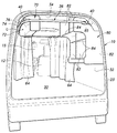
本実施形態の室内構造が適用される自動車は、ハッチバックタイプのワンボックスカーである。ワンボックスカーは、図1、図2に示されているように、箱形の車体10と、車体10内(車室内)の前部に配置された前部座席(運転席と助手席)12と、前部座席12の後方の車体10内に配置された折りたたみ可能な後部座席(図示省略)と、後部座席の後方の車体10内に設けられたラゲッジスペース部(荷室部)14と、前部座席12の前方に設けられた前部窓(フロントシールドガラス)15と、車体10の側部前側に設けられた窓付きの左右のフロントサイドドア16と、車体10の側部後側に設けられた窓付きの左右のリアサイドドア18と、リアサイドドア18よりも後方位置で、ラゲッジスペース部14の左右両側部分の車体10に設けられた側部窓20と、車体10の後部に設けられた跳ね上げ式の窓付きのテールゲート22とを有する。テールゲート22は、車体10の後部開口23を開閉するものである。
The automobile to which the indoor structure of the present embodiment is applied is a hatchback type one-box car. As shown in FIGS. 1 and 2, the one-box car includes a box-
このワンボックスカーは、図示されていない後部座席が折りたたまれることにより、前部座席12よりも後方の車室空間が、車室内の所定領域として、ラゲッジスペース部14を含むフラットフロアによる一つのキャンピング居住エリア30になる。キャンピング居住エリア30に対する人の出入りおよび荷物の出し入れは、リアサイドドア18の開口(図示省略)と後部開口23とによって行われる。
In this one-box car, a rear seat (not shown) is folded so that a vehicle compartment space behind the
車室内の上部にはキャンピング居住エリア30の全周に亘って外囲するように、車室の側壁32(図3参照)の上部及び天井壁34(図3参照)に沿って、且つこれらに近接して無端環状に延在するカーテンレール36が取り付けられている。カーテンレール36は全体を円環状横断面のアルミニウム合金やステンレス鋼等の金属製の丸パイプによって構成されて全長に亘って円筒状をなしていて、前部座席12の後側近傍を車幅方向に延在する前部直管36Aと、テールゲート22の前側近傍を車幅方向に延在する後部直管36Bと、車内右側を車体前後方向に延在する右部直管36Cと、車内左側を車体前後方向に延在する左部直管36Dと、前部直管36Aの右端部と右部直管36Cの前端部とを接続する1/4円弧による前右曲管36Eと、前部直管36Aの左端部と左部直管36Dの前端部とを接続する1/4円弧による前左曲管36Fと、後部直管36Bの右端部と右部直管36Cの後端部とを接続する1/4円弧による後右曲管36Gと、後部直管36Bの左端部と左部直管36Dの後端部とを接続する1/4円弧による後左曲管36Hとの溶接組立体によって略四角形状の無端環状をなしている。
The upper part of the passenger compartment is surrounded by the upper part of the
カーテンレール36は、右側と左側の各々の車体前後方向の4箇所、合計8箇所を、つまりカーテンレール36の長手方向に沿う複数個所をブラケット40によって側壁32の上部に取り付けられている。
The
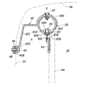
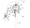
次に、ブラケット40によるカーテンレール36の取付構造について、図3を参照して詳細に説明する。ブラケット40は、金属板のプレス成形品あるいは樹脂成形品であり、一端にあってカーテンレール36の上側外周半分に係合する半円形湾曲部40Aと、他端にあって側壁32に対する固定のための平片部40Bと、半円形湾曲部40Aと平片部40Bとの間にあってカーテンレール36を側壁32の上部及び天井壁34より間隔A、Bだけ離して配置するために折曲された折曲中間部40Cとを一体に有する。
Next, the attachment structure of the
半円形湾曲部40Aはポップリベットと言われているブラインドリベット42によってカーテンレール36の上部に固定されている。平片部40Bは平片部40Bに貫通形成されたボルト通し孔40Dに通された取付ボルト44が車体側部メンバ46に固定されたナット48にねじ係合することにより、側壁32の上部に固定されている。これにより、カーテンレール36は、側壁32の上部及び天井壁34に対して車室内側に間隔A、Bを置いて、且つ水平に、キャンピング居住エリア30の上部を取り囲むように、側壁32の上部に取り付けられている。
The semicircular
カーテンレール36の下部には、カーテンレール36の全長に亘って延在する所定幅(カーテンレール36の円周方向の幅)の開口50が形成されている。開口50は、カーテンレール36を一周ぐるりと、カーテンレール36と同様に、無端環状に延在している。
An
カーテンレール36の一箇所には、図4に示されているように、開口50の開口幅をカーテンレール36の円周方向に拡大した四角形状のランナー出入口54が形成されている。ランナー出入口54は、開口50の両縁部を四角形状に拡大したものであって、ランナー60のローラ配置部60A(図3参照)をカーテンレール36の内外に通過可能にするものであり、ランナー60のローラ配置部60Aをカーテンレール36に対して出し入れすることに用いられる。
As shown in FIG. 4, a
カーテンレール36には、ランナー出入口54部分のランナー60の通過を許すように、開口50を残してランナー出入口54を塞ぐプラグ56が取り付けられている。プラグ56は、ランナー出入口54の補形をなしてランナー出入口54に嵌合する嵌合部56Aと、嵌合部56Aの外端側に一体形成されてカーテンレール36の外面に接合するフランジ部56Bとを有し、ランナー出入口54に対する嵌め合いあるいは接着剤によってカーテンレール36に固定される。
A
嵌合部56Aの厚さはランナー出入口54におけるカーテンレール36の肉厚に等しいので、ランナー出入口54に嵌められた嵌合部56Aは、ランナー出入口54において他の部分と面一に連続するローラ走行面をカーテンレール36内に構成する。これにより、ランナー出入口54においてもランナー60が段差なく滑らかに走行する。
Since the thickness of the
カーテンレール36は、先ず前部直管36Aと後部直管36Bと右部直管36Cと左部直管36Dと前右曲管36Eと前左曲管36Fと後右曲管36Gと後左曲管36Hとの合計8個の丸パイプ材を溶接によって互いに接合して略四角形状の無端環状体を製作し、その後、無端環状体をワーク保持治具にセットし、NC制御による切削加工によって開口50とランナー出入口54とを作成することによって製造することができる。
First, the
この製造工程によれば、無端環状体を製作した後に開口50を無端環状に削り出すので、カーテンレール36の全長に亘って延在する開口50の無端連続性の精度がよく、丸パイプ材の接合部において開口50に不要な筋違いが生じることを完全に排除できる。
According to this manufacturing process, since the
カーテンレール36には複数のランナー(スライダ)60が取り付けられている。ランナー60は、カーテンレール36内に位置するローラ配置部60Aと、ローラ配置部60Aより下方にあって開口50を通過してカーテンレール36よりも下方に突出するカーテン吊り下げ部60Bとを一体に有する。ローラ配置部60Aの両側にはローラ60Cが回転自在に取り付けられている。両ローラ60Cがカーテンレール36内において開口50の両側縁部上を転動することにより、ランナー60が開口50に案内されてカーテンレール36の延在方向に走行移動する。カーテン吊り下げ部60Bには、カーテンレール36外において開口50の両側縁部に小さい間隔をおいて対向する上下方向のストッパ部60Dが突出形成されていると共に、カーテンフック62を掛けられる係合孔60Eが貫通形成されている。
A plurality of runners (sliders) 60 are attached to the
カーテンフック62には布製等のカーテン64の上部が取り付けられている。カーテン64は、カーテンフック62、ランナー60を介してカーテンレール36より吊り下げられ、ランナー60がカーテンレール36の延在方向に沿って走行移動することにより、カーテンレール36の延在方向に沿って開け閉めされる。
An upper portion of a
カーテン64は、カーテンレール36の延在方向の全域に亘る長さを有するものであり、カーテン64の枚数はカーテン64の長さによって決まる。カーテン64の枚数は、カーテン64の長さがカーテンレール36の全長に相当するものであれば1枚でよく、カーテン64の長さがカーテンレール36の全長の1/2に相当するものであれば2枚でよく、カーテン64の長さがカーテンレール36の全長の1/3に相当するものであれば3枚でよい。図1はカーテンレール36に2枚のカーテン64を吊り下げた実施形態を示している。
The
カーテンレール36は、キャンピング居住エリア30を全周に亘って外囲するように無端環状に延在するから、このカーテンレール36に吊り下げられたカーテン64によってキャンピング居住エリア30の前後左右の全体を囲むことができる。これにより、キャンピング居住エリア30の全方向に亘ってのプライバシー保護および遮光が、無端環状に連続する一つのカーテンレール36に吊り下げられたカーテン64の簡単な開け閉め操作によって確実に行われるようになる。
Since the
カーテンレール36は無端環状であるから全体の剛性が高い。このことと、カーテンレール36がブラケット40によって側壁32の上部及び天井壁34に対して車室内側に間隔A、Bを置いて、且つ水平に設けられていることとから、カーテンレール36を、ハンガ等の物品を吊るすためのハンガバーや、キャンピング居住エリア30に配備する各種備品を車体10に取り付けるための取付バーとして適切に利用することができる。
Since the
特に、カーテンレール36が円筒状であることにより、カーテンレール36に吊るすハンガが衣服を掛けるハンガの場合、カーテンレール36のハンガバーとしての使い勝手がよく、カーテンレール36のハンガバーとしての使用の違和感も軽減される。
In particular, since the
キャンピング居住エリア30の左側の天井部には、図1、図2に示されているように、頭上収納棚ユニット(第1の備品)70がカーテンレール36に近接して固定配置されている。頭上収納棚ユニット70は、天井壁34やカーテンレール36の側部に固定されており、カーテンレール36の下側に、カーテンレール36からランナー60を介して吊り下げられたカーテン64よりも車室内側に位置する背面72、74、76を有している。これにより、頭上収納棚ユニット70の背面72、74、76と側壁32の上部との間にカーテン64の通過を自由に許す空間Cが設けられる。
As shown in FIG. 1 and FIG. 2, an overhead storage shelf unit (first equipment) 70 is fixedly disposed near the
この構造により、頭上収納棚ユニット70の配置部の背面側をカーテン64が頭上収納棚ユニット70により阻害されることなく通ることができ、頭上収納棚ユニット70の配置部の背面側、本実施形態では左側の側部窓20をカーテン64によって覆うことができる。このように、キャンピング居住エリア30に設置された頭上収納棚ユニット70に阻害されることなくカーテン64を開け閉めすることができ、キャンピング居住エリア30の利便性が向上する。
With this structure, the
キャンピング居住エリア30の右側には、図1、図2に示されているように、側壁収納棚ユニット(第2の備品)80がカーテンレール36に近接して着脱可能に設置されている。側壁収納棚ユニット80は、複数の垂直な端板82と複数の水平な棚板84とを含むものである。
As shown in FIGS. 1 and 2, a side wall storage shelf unit (second equipment) 80 is detachably installed in the vicinity of the
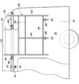
図5、図6に示されているように、カーテンレール36が車体10の右側を前後方向に延在する部分の車体前後方向に離れた2箇所の車内側の側面にはパッチン錠と呼ばれるドローラッチ金具(固定具)86のフック部材86Aが固定されている。側壁収納棚ユニット80の車体前後方向に離れた2枚の端板82の上部にはフック部材86Aに係脱可能に係合するドローラッチ金具86のラッチ部材86Bが取り付けられている。
As shown in FIG. 5 and FIG. 6, draw latches called “patton locks” are provided on two side surfaces inside the vehicle body in the longitudinal direction of the
これにより、側壁収納棚ユニット80は、上部の2箇所をドローラッチ金具86によってワンタッチで工具なしで、カーテンレール36に係脱可能に固定される。
Thereby, the side wall
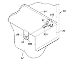
図5、図7に示されているように、側壁収納棚ユニット80の最下段の棚板84の背面部には車体前後方向に離れた2箇所に取付片88が取り付けられている。取付片88は、棚板84より垂下しており、ボルト通し孔88Aを貫通形成されている。ボルト通し孔88Aには締結ボルト(固定具)92の雄ねじ部92Aが貫通している。ボルト通し孔88Aに通された締結ボルト92は、雄ねじ部92Aが側壁32に予め配備されたナット部材90にねじ係合することにより、側壁収納棚ユニット80を側壁32に取り外し可能に固定する。締結ボルト92の頭部は小物吊り下げ用のフックを兼ねた手廻しハンドル部92Bになっている。
As shown in FIGS. 5 and 7,
これにより、側壁収納棚ユニット80は、下部の2箇所を締結ボルト92によって工具なしで、側壁32に係脱可能に固定される。
Thereby, the side wall
側壁収納棚ユニット80の上部はカーテンレール36に取り付けられるから、側壁収納棚ユニット80の取り付けのためにカーテンレール36が有効に利用され、それ故にカーテンレール36が側壁収納棚ユニット80の取り付けを阻害することがない。これにより、側壁収納棚ユニット80の取り付けのための構造が簡単になると共に省スペースが図られる。
Since the upper part of the side wall
更に、端板82にカーテンレール36を避ける凹部85(図1参照)を設けることにより、カーテンレール36に阻害されることなく、車室の側壁上部のスペースを効率的に利用して側壁収納棚ユニット80を配置することができる。
Furthermore, by providing the
側壁収納棚ユニット80は、工具を用いることなく簡単に取り外すことができるので、キャンピングカー以外の使用等において側壁収納棚ユニット80が不必要な場合には、側壁収納棚ユニット80を取り外すことによってラゲッジスペース部14、キャンピング居住エリア30を広く使うことができる。
The side wall
側壁収納棚ユニット80が側部窓20を覆うような比較的大型のものであったり、窓以外の車室側壁の部分に配置されるものであったりしても、側壁収納棚ユニット80を避けるようにカーテン64を配置し、側壁収納棚ユニット80とカーテン64とが互いに協働して、キャンピング居住エリア30を実質的に全周に亘って覆うことができる。しかも、側壁収納棚ユニット80を取り外したときには、カーテン64によってキャンピング居住エリア30を実質的に全周に亘って覆うことができ、状況に応じてカーテン64を好適に且つフレキシブルに使用することができる。
Even if the side wall
次に、本発明による自動車の室内構造のカーテン吊り下げ部60Bの他の実施形態を、図8を参照して説明する。なお、図8において、図3に対応する部分は、図3に付した符号と同一の符号を付けて、その説明を省略する。
Next, another embodiment of the
この実施形態では、カーテンレール36の開口50が、カーテンレール36の真下位置よりキャンピング居住エリア30外側方向にオフセットした位置に設けられている。このことに応じてランナー60はくの字形に折曲した形状になっており、ローラ配置部60Aは開口50のオフセットに応じて傾斜しているが、係合孔60Eの部分はカーテン64の鉛直な吊り下げのために垂直(鉛直)になっている。
In this embodiment, the
この構成によれば、開口50がカーテンレール36の真下位置にある場合に比してカーテンレール36のやや外側寄りの下方部分からカーテン64が垂下することとなり、カーテン64の開閉に干渉することなく、より一層好適に物品をカーテンレール36から吊り下げたり、或いは取り付けたりすることができる。
According to this configuration, the
以上、本発明を、その好適な実施形態について説明したが、当業者であれば容易に理解できるように、本発明はこのような実施形態により限定されるものではなく、本発明の趣旨を逸脱しない範囲で適宜変更可能である。 Although the present invention has been described above with reference to preferred embodiments thereof, the present invention is not limited to such embodiments and can be deviated from the spirit of the present invention, as will be readily understood by those skilled in the art. It is possible to change appropriately within the range not to be.
たとえば、ブラケット40の一部あるいは全部が天井壁34に取り付けられていてもよい。また、ランナー出入口54はカーテンレール36の複数箇所に形成されていもよい。
For example, part or all of the
また、上記実施形態に示した構成要素は必ずしも全てが必須なものではなく、本発明の趣旨を逸脱しない限りにおいて適宜取捨選択することが可能である。 In addition, all the components shown in the above embodiment are not necessarily essential, and can be appropriately selected without departing from the gist of the present invention.
10 車体
12 前部座席
14 ラゲッジスペース部
30 キャンピング居住エリア(所定領域)
32 側壁
34 天井壁
36 カーテンレール
40 ブラケット
60 ランナー
64 カーテン
70 頭上収納棚ユニット(第1の備品)
72 背面
80 側壁収納棚ユニット(第2の備品)
85 凹部
86 ドローラッチ金具(固定具)
92 締結ボルト(固定具)
10
32
72
85
92 Fastening bolt (fixture)
Claims (7)
車室内の所定領域を全周に亘って外囲するように車室の側壁上部及び又は天井壁に沿って無端環状に延在するカーテンレールと、
前記カーテンレールの長手方向に沿う複数個所にて、前記カーテンレールを前記側壁上部及び又は天井壁に、同部分に対して間隔を置くように固定する複数のブラケットとを有し、
前記カーテンレールは、全長に亘って筒状をなし、下部位置に全長に亘って延在する開口を有することを特徴とする自動車の室内構造。 The interior structure of a car,
A curtain rail extending in an endless annular manner along the upper part of the side wall of the passenger compartment and / or the ceiling wall so as to surround a predetermined region of the passenger compartment over the entire circumference;
A plurality of brackets for fixing the curtain rail to the upper portion of the side wall and / or the ceiling wall at a plurality of locations along the longitudinal direction of the curtain rail so as to be spaced from the same portion;
An interior structure of an automobile, wherein the curtain rail has a cylindrical shape over its entire length and has an opening extending over the entire length at a lower position.
前記第1の備品は、前記カーテンレールの下側に、前記カーテンレールからランナーを介して吊るされるカーテンよりも車室内側に位置する背面を有し、
前記第1の備品の前記背面と前記側壁上部との間に前記カーテンの通過を許す空間が設けられている請求項1に記載の自動車の室内構造。 A first fixture fixedly disposed adjacent to the curtain rail in the predetermined area;
The first equipment has a back surface located on the vehicle interior side of a curtain suspended from the curtain rail via a runner on the lower side of the curtain rail,
The interior structure of an automobile according to claim 1, wherein a space allowing passage of the curtain is provided between the back surface of the first fixture and the upper portion of the side wall.
Priority Applications (1)
| Application Number | Priority Date | Filing Date | Title |
|---|---|---|---|
| JP2012280413A JP5792708B2 (en) | 2012-12-24 | 2012-12-24 | Interior structure of automobile and curtain rail for vehicle compartment |
Applications Claiming Priority (1)
| Application Number | Priority Date | Filing Date | Title |
|---|---|---|---|
| JP2012280413A JP5792708B2 (en) | 2012-12-24 | 2012-12-24 | Interior structure of automobile and curtain rail for vehicle compartment |
Publications (2)
| Publication Number | Publication Date |
|---|---|
| JP2014122012A true JP2014122012A (en) | 2014-07-03 |
| JP5792708B2 JP5792708B2 (en) | 2015-10-14 |
Family
ID=51402897
Family Applications (1)
| Application Number | Title | Priority Date | Filing Date |
|---|---|---|---|
| JP2012280413A Active JP5792708B2 (en) | 2012-12-24 | 2012-12-24 | Interior structure of automobile and curtain rail for vehicle compartment |
Country Status (1)
| Country | Link |
|---|---|
| JP (1) | JP5792708B2 (en) |
Cited By (2)
| Publication number | Priority date | Publication date | Assignee | Title |
|---|---|---|---|---|
| CN106740347A (en) * | 2016-12-13 | 2017-05-31 | 郑州宇通客车股份有限公司 | A kind of lactation enclosure device and the utility car using the device |
| WO2024209716A1 (en) * | 2023-04-03 | 2024-10-10 | Vantech株式会社 | Recreational vehicle |
Citations (6)
| Publication number | Priority date | Publication date | Assignee | Title |
|---|---|---|---|---|
| JPS62136883U (en) * | 1986-02-24 | 1987-08-28 | ||
| JPH07329644A (en) * | 1994-06-03 | 1995-12-19 | Hino Motors Ltd | Container for installation on curtain rail |
| JPH09193702A (en) * | 1996-01-16 | 1997-07-29 | Honda Motor Co Ltd | Car curtain |
| JPH1178519A (en) * | 1997-09-16 | 1999-03-23 | Hiroshi Mori | Curtain device for automobile compartment |
| JP3115151U (en) * | 2005-07-27 | 2005-11-04 | 株式会社ミラリード | Car curtain |
| JP2006240607A (en) * | 2005-02-28 | 2006-09-14 | Tomoya Kasugai | Curtain rail mounting structure of automobile and mounting method |
-
2012
- 2012-12-24 JP JP2012280413A patent/JP5792708B2/en active Active
Patent Citations (6)
| Publication number | Priority date | Publication date | Assignee | Title |
|---|---|---|---|---|
| JPS62136883U (en) * | 1986-02-24 | 1987-08-28 | ||
| JPH07329644A (en) * | 1994-06-03 | 1995-12-19 | Hino Motors Ltd | Container for installation on curtain rail |
| JPH09193702A (en) * | 1996-01-16 | 1997-07-29 | Honda Motor Co Ltd | Car curtain |
| JPH1178519A (en) * | 1997-09-16 | 1999-03-23 | Hiroshi Mori | Curtain device for automobile compartment |
| JP2006240607A (en) * | 2005-02-28 | 2006-09-14 | Tomoya Kasugai | Curtain rail mounting structure of automobile and mounting method |
| JP3115151U (en) * | 2005-07-27 | 2005-11-04 | 株式会社ミラリード | Car curtain |
Cited By (2)
| Publication number | Priority date | Publication date | Assignee | Title |
|---|---|---|---|---|
| CN106740347A (en) * | 2016-12-13 | 2017-05-31 | 郑州宇通客车股份有限公司 | A kind of lactation enclosure device and the utility car using the device |
| WO2024209716A1 (en) * | 2023-04-03 | 2024-10-10 | Vantech株式会社 | Recreational vehicle |
Also Published As
| Publication number | Publication date |
|---|---|
| JP5792708B2 (en) | 2015-10-14 |
Similar Documents
| Publication | Publication Date | Title |
|---|---|---|
| JP4286258B2 (en) | Rail vehicle | |
| BR102016007167B1 (en) | SECTION DIVIDER SYSTEM | |
| KR101759036B1 (en) | A Camping Car | |
| EP0985793A2 (en) | Sliding door | |
| EP3142922B1 (en) | Bulkhead assembly with pocket door for aircraft interior | |
| JP5792708B2 (en) | Interior structure of automobile and curtain rail for vehicle compartment | |
| US20200318410A1 (en) | Sliding screen door system | |
| US10160386B2 (en) | Retractable storage compartment | |
| US5593203A (en) | Retrofitted door for open luggage rack on passenger busses | |
| US10875393B2 (en) | Cargo storage assembly for sport utility vehicle | |
| US3354584A (en) | Vehicle body trim attachment | |
| CN201800644U (en) | Object-shielding curtain hanging structure on rear-pillar lower decorative plate of automobile | |
| JP7141188B2 (en) | Railway vehicle and equipment mounting structure | |
| CN217176244U (en) | Move door with outer suspension formula guidance system and have its cupboard | |
| JP6179236B2 (en) | Door pocket frame structure | |
| JP2023032774A (en) | Vehicular cargo chamber | |
| EP2933126B1 (en) | Sliding door for vehicles | |
| JPH04101644U (en) | Workbench | |
| CN222629085U (en) | Sunshade screen mounting structure and vehicle | |
| JP6194904B2 (en) | Car door structure | |
| JP6094445B2 (en) | Vehicle door mounting structure | |
| JP2006089009A (en) | Blinder sheet | |
| US1744136A (en) | Window-shade-support for motor vehicles | |
| CN210653100U (en) | Cab partition wall door for subway vehicle | |
| JP2025103474A (en) | Sliding frame for vehicle tailgate |
Legal Events
| Date | Code | Title | Description |
|---|---|---|---|
| A621 | Written request for application examination |
Free format text: JAPANESE INTERMEDIATE CODE: A621 Effective date: 20140911 |
|
| A977 | Report on retrieval |
Free format text: JAPANESE INTERMEDIATE CODE: A971007 Effective date: 20150514 |
|
| A131 | Notification of reasons for refusal |
Free format text: JAPANESE INTERMEDIATE CODE: A131 Effective date: 20150519 |
|
| A521 | Request for written amendment filed |
Free format text: JAPANESE INTERMEDIATE CODE: A523 Effective date: 20150624 |
|
| TRDD | Decision of grant or rejection written | ||
| A01 | Written decision to grant a patent or to grant a registration (utility model) |
Free format text: JAPANESE INTERMEDIATE CODE: A01 Effective date: 20150804 |
|
| A61 | First payment of annual fees (during grant procedure) |
Free format text: JAPANESE INTERMEDIATE CODE: A61 Effective date: 20150806 |
|
| R150 | Certificate of patent or registration of utility model |
Ref document number: 5792708 Country of ref document: JP Free format text: JAPANESE INTERMEDIATE CODE: R150 |
|
| R250 | Receipt of annual fees |
Free format text: JAPANESE INTERMEDIATE CODE: R250 |
|
| R250 | Receipt of annual fees |
Free format text: JAPANESE INTERMEDIATE CODE: R250 |
|
| R250 | Receipt of annual fees |
Free format text: JAPANESE INTERMEDIATE CODE: R250 |
|
| R250 | Receipt of annual fees |
Free format text: JAPANESE INTERMEDIATE CODE: R250 |
|
| R250 | Receipt of annual fees |
Free format text: JAPANESE INTERMEDIATE CODE: R250 |
|
| R250 | Receipt of annual fees |
Free format text: JAPANESE INTERMEDIATE CODE: R250 |
|
| R250 | Receipt of annual fees |
Free format text: JAPANESE INTERMEDIATE CODE: R250 |