JP2014141995A - Flange-connecting portion reinforcement fixture - Google Patents
Flange-connecting portion reinforcement fixture Download PDFInfo
- Publication number
- JP2014141995A JP2014141995A JP2013009609A JP2013009609A JP2014141995A JP 2014141995 A JP2014141995 A JP 2014141995A JP 2013009609 A JP2013009609 A JP 2013009609A JP 2013009609 A JP2013009609 A JP 2013009609A JP 2014141995 A JP2014141995 A JP 2014141995A
- Authority
- JP
- Japan
- Prior art keywords
- flange
- fitting portion
- pressing
- bolt
- fastening
- Prior art date
- Legal status (The legal status is an assumption and is not a legal conclusion. Google has not performed a legal analysis and makes no representation as to the accuracy of the status listed.)
- Granted
Links
Images






Landscapes
- Flanged Joints, Insulating Joints, And Other Joints (AREA)
Abstract
【課題】両フランジ部を含む管路を所定の耐震性能を備えた耐震管路に補強しつつ、両フランジ部の離間やずれを簡便且つ安価に防止できるフランジ接合部補強治具の提供。
【解決手段】ボルト連結されている両フランジ部1A、1Bの外側面1a、1aに各別に当接可能な押圧部5C、6Bを備えた一対の挟持部材5、6と、この両挾持部材5、6の押圧部5C、6Bを両フランジ部1A、1Bの外側面1a、1aに当て付けた状態で当該両挾持部材5、6をフランジ接合方向に引き寄せて締付固定する締結手段7とを備えたフランジ接合部補強治具Pであって、両挾持部材5、6のフランジ接合方向で相対向する部位に、両フランジ部1A、1Bの外周面1c、1cよりも径方向外方側位置においてフランジ接合方向から嵌合する内嵌合部5Aと外嵌合部6Aとが形成されている。
【選択図】図6Provided is a flange joint reinforcement jig that can easily and inexpensively prevent separation and displacement of both flange portions while reinforcing a pipeline including both flange portions to an earthquake resistant pipeline having predetermined earthquake resistance.
A pair of sandwiching members (5, 6) having pressing portions (5C, 6B) capable of abutting against outer surfaces (1a, 1a) of both flange portions (1A, 1B) connected to bolts, and the both sandwiching members (5). , 6 with the pressing parts 5C, 6B applied to the outer side surfaces 1a, 1a of the flange parts 1A, 1B, and the fastening means 7 for pulling and fixing the holding members 5, 6 in the flange joining direction. It is the flange joint part reinforcement jig | tool P which was equipped, Comprising: The position where both the holding members 5 and 6 mutually oppose in the flange joining direction is a radial direction outer side position rather than the outer peripheral surfaces 1c and 1c of both flange parts 1A and 1B. 5A, an inner fitting portion 5A and an outer fitting portion 6A that are fitted from the flange joining direction are formed.
[Selection] Figure 6
Description
本発明は、ボルト連結されている両フランジ部の外側面に各別に当接可能な押圧部を備えた一対の挟持部材と、この両挾持部材の押圧部を両フランジ部の外側面に当て付けた状態で当該両挾持部材をフランジ接合方向に引き寄せて締付固定する締結手段とを備えたフランジ接合部補強治具に関する。 The present invention relates to a pair of clamping members each having a pressing portion that can be brought into contact with the outer surface of both flange portions that are bolted together, and the pressing portions of the both holding members applied to the outer surfaces of both flange portions. It is related with the flange joint part reinforcement jig provided with the fastening means which draws both the said holding members in the flange joining direction in the state where it clamped, and is fastened and fixed.
かかるフランジ接合部補強治具として、例えば、特許文献1には、両挟持部材のフランジ接合方向で相対向する部位に、両フランジ部の外周面よりも径方向外方側位置に形成された一対のボルト螺合孔(締結手段の一例)が形成され、両挟持部材においてボルト螺合孔よりも径方向内方側位置に形成された押圧部を両フランジ部の外側面に当て付けた状態で、両ネジボルト(締結手段の一例)を一対のボルト螺合孔に亘って螺合させた構成が開示されている。
As such a flange joint portion reinforcing jig, for example, in
また、かかるフランジ接合部補強治具として、例えば、特許文献2には、両挟持部材の一方が一対の脚部を備えた概略コ字形状部材で構成され、両挟持部材の他方が一対の脚部のうちの一方に螺合装着されるボルト(締結手段の一例)により構成されており、ボルトの先端及びコ字形状部材の当該ボルトが装着されていない他方の脚部の内周面が、両フランジ部の外側面を各別に押圧する押圧部とされた構成が開示されている。そして、一方の脚部にボルトを螺合させ、更に締め込むことにより、ボルトの先端及び他方の脚部の内周面をフランジ部の外側面に各別に当接させて、一対の挟持部材(コ字形状部材及びボルト)によりフランジ部を締付固定する構成とされている。
Further, as such a flange joint reinforcing jig, for example, in
これらフランジ接合部補強治具を用いて、一対の挟持部材を締結手段により締付固定することで、複数のボルト・ナットによる両フランジ部の接合強度に加えて、締結手段による締結強度も付加することができ、両フランジ部に曲げ方向或いは引張方向に力が作用した場合でも、両フランジ部が離間することを防止して気密性を保持できるとされている。 By using these flange joint reinforcement jigs, a pair of clamping members are fastened and fixed by fastening means, thereby adding fastening strength by fastening means in addition to the joint strength of both flanges by a plurality of bolts and nuts. Even when a force is applied to both flange portions in the bending direction or the pulling direction, the flange portions can be prevented from separating and airtightness can be maintained.
ここで、両フランジ部を含む管路の耐震性をより向上させるために、既存或いは新設の両フランジ部を、耐震管路と同等(離脱防止力が3DkN以上(Dは呼び径))の耐震性能A級の性能を有するものに補強することが望まれる。
また、両フランジ部に曲げ方向或いは引張方向の力が作用した場合でも、両フランジ部の離間を防止し、内部を通流する流体の漏洩を確実に防止できる構成とすることが望まれる。
更に、両フランジ部の一方が短管や補修弁等の一端側に形成されたフランジ部である場合には、当該両フランジ部にフランジ接合部補強治具を装着する際、当該フランジ接合部補強治具が短管や補修弁等の他端側に形成されたフランジ部に干渉する可能性があるため、当該干渉をできるだけ防止できる構成とすることが望まれる。
Here, in order to further improve the seismic resistance of the pipes including both flange parts, the existing or newly installed both flange parts are equivalent to the seismic pipes (with an anti-separation force of 3DkN or more (D is the nominal diameter)). It is desired to reinforce what has a performance class A performance.
In addition, even when a force in the bending direction or the tensile direction is applied to both flange portions, it is desirable that the both flange portions be prevented from separating and the fluid flowing through the interior can be reliably prevented from leaking.
Furthermore, when one of the flange portions is a flange portion formed on one end side of a short pipe or a repair valve, the flange joint portion reinforcement is applied when the flange joint portion reinforcing jig is attached to the both flange portions. Since there is a possibility that the jig interferes with the flange portion formed on the other end side of the short pipe, the repair valve, etc., it is desirable to have a configuration that can prevent the interference as much as possible.
これら点について着目すると、上記特許文献1に開示のフランジ接合部補強治具では、両フランジ部の外側面に各別に当接する押圧部を備えた一対の挟持部材が、当該押圧部の径方向外方側に形成された一対のボルト螺合孔に亘って螺合させた両ネジボルトにより締付固定されており、一対の挟持部材は実質的に一対のボルト螺合孔及び両ネジボルトのみで締付固定されているに過ぎず、両フランジ部に曲げ方向或いは引張方向の力が作用した際には、当該力が、フランジ部及び一対の挟持部材を介して一対のボルト螺合孔と両ネジボルトとの螺合箇所に集中し、両ネジボルトが伸長したり、螺合箇所のねじ山が破壊される等する場合があり、両フランジ部が離間する可能性がある。この場合、両フランジ部間から流体が漏洩する可能性があるとともに、両フランジ部を上述の耐震管路と同等の耐震性能を有する程度にまで補強することは困難となる。
Focusing on these points, in the flange joint reinforcing jig disclosed in
また、上記特許文献2に開示のフランジ接合部補強治具では、ボルトがコ字形状部材の一方の脚部に管軸方向の外方側から螺合装着され、当該ボルトの先端がフランジ部の外側面に当接する構成とされている。このため、コ字形状部材の管軸方向の外方側部位には、ボルトを一方の脚部に螺合装着させるための作業用空間が必要となり、両フランジ部の一方が短管や補修弁等の一端側に形成されたフランジ部である場合には、両フランジ部にフランジ接合部補強治具を装着する際、当該フランジ接合部補強治具のボルトが短管や補修弁等の他端側に形成されたフランジ部に干渉して装着が困難或いは不能となる可能性がある。また、ボルトの先端がフランジの外側面に当接すると当該外側面に傷がつき腐食等の原因になるとともに、当該傷を防止するためにボルトの先端に保護部材を装着すると、当該ボルトがコ字形状部材の管軸方向の外方側部位に突出する突出代が大きくなり、当該外方側部位に大きな作業用空間を形成しなければフランジ接合部補強治具を両フランジ部に装着することがより一層困難或いは不能となる可能性がある。
Further, in the flange joint reinforcing jig disclosed in
本発明は、かかる実情に鑑みてなされたものであり、その目的は、両フランジ部を含む管路を所定の耐震性能を備えた耐震管路に補強しつつ、両フランジ部の離間やずれを簡便且つ安価に防止できるフランジ接合部補強治具を提供することにある。 The present invention has been made in view of such a situation, and its purpose is to reinforce a pipe including both flanges to an earthquake-resistant pipe having a predetermined seismic performance, and to separate and shift both flanges. An object of the present invention is to provide a flange joint reinforcing jig that can be easily and inexpensively prevented.
上記目的を達成するための本発明に係るフランジ接合部補強治具は、ボルト連結されている両フランジ部の外側面に各別に当接可能な押圧部を備えた一対の挟持部材と、この両挾持部材の押圧部を両フランジ部の外側面に当て付けた状態で当該両挾持部材をフランジ接合方向に引き寄せて締付固定する締結手段とを備えたフランジ接合部補強治具であって、その特徴構成は、
前記両挾持部材のフランジ接合方向で相対向する部位に、前記両フランジ部の外周面よりも径方向外方側位置においてフランジ接合方向から嵌合する内嵌合部と外嵌合部とが形成されている点にある。
In order to achieve the above object, a flange joint reinforcing jig according to the present invention comprises a pair of clamping members each having a pressing portion capable of abutting against the outer surface of both flanges connected to each other by bolts. A flange joint reinforcement jig comprising a fastening means for pulling and fixing both gripping members in the flange joining direction in a state where the pressing portions of the gripping members are applied to the outer surfaces of both flanges, The feature configuration is
An inner fitting portion and an outer fitting portion that are fitted from the flange joining direction at a radially outer side position than the outer peripheral surface of the both flange portions are formed at portions facing each other in the flange joining direction of the both holding members. It is in the point.
上記特徴構成によれば、一対の挟持部材におけるフランジ接合方向で相対向する各部位に、両フランジ部の外周面よりも径方向外方側位置においてフランジ接合方向から嵌合する内嵌合部と外嵌合部とが形成されているので、一対の挟持部材の各押圧部を両フランジ部の外側面に各別に当て付けた状態で締結手段を締付けると、両挟持部材がフランジ接合方向に引き寄せられるにつれて、内嵌合部が外嵌合部内に嵌合し、内嵌合部と外嵌合部とがフランジ接合方向(軸方向)で重なった状態となる。
これにより、一対の挟持部材が締結手段により締付固定された状態で、両フランジ部に曲げ方向(径方向)への力が作用した場合でも、締結手段の締結部位に加えて、内嵌合部と外嵌合部との重なり部位でも当該力を受け止めることができ、締結手段の締結部位に掛かる応力の低減を図ることができる。従って、フランジ接合部補強治具による両フランジ部の接合強度を向上させて、両フランジ部の離間やずれ及びこれらに伴う流体の漏洩を防止することができ、管路の耐震性能の向上をも図ることができる。
よって、両フランジ部を含む管路を所定の耐震性能(離脱防止力が3DkN以上(Dは呼び径))を備えた耐震管路に補強しつつ、両フランジ部の離間やずれを簡便且つ安価に防止することができる。
According to the above characteristic configuration, the inner fitting portions that are fitted from the flange joining direction at positions radially outward from the outer peripheral surfaces of the two flange portions to the respective portions facing each other in the flange joining direction of the pair of holding members. Since the outer fitting part is formed, if the fastening means is tightened with the pressing parts of the pair of clamping members applied to the outer surfaces of the flange parts separately, the clamping members are pulled in the flange joining direction. As a result, the inner fitting portion is fitted into the outer fitting portion, and the inner fitting portion and the outer fitting portion are overlapped in the flange joining direction (axial direction).
As a result, even when a force in the bending direction (radial direction) acts on both flange portions in a state where the pair of clamping members are clamped and fixed by the fastening means, in addition to the fastening part of the fastening means, the inner fitting The force can be received even at the overlapping portion of the portion and the outer fitting portion, and the stress applied to the fastening portion of the fastening means can be reduced. Therefore, it is possible to improve the joint strength of both flange portions by the flange joint reinforcement jig, to prevent separation and displacement of both flange portions and fluid leakage accompanying them, and to improve the seismic performance of the pipeline. Can be planned.
Therefore, while reinforcing the pipeline including both flanges to a seismic pipeline with a predetermined seismic performance (with an anti-separation force of 3DkN or more (D is the nominal diameter)), separation and displacement of both flanges is simple and inexpensive. Can be prevented.
本発明に係るフランジ接合部補強治具の更なる特徴構成は、前記両挾持部材の前記内嵌合部と前記外嵌合部とが嵌合している状態において、一方の挾持部材の押圧部と前記内嵌合部と他方の挾持部材の押圧部と前記外嵌合部とで形成される凹部が、両フランジ部におけるボルト連結箇所の隣接間部位に対して径方向外方から外嵌装着可能に構成されているとともに、前記外嵌合部が、両フランジ部の外周面との当接によって設定外嵌装着位置に規制する装着規制部に構成されている点にある。 A further characteristic configuration of the flange joint reinforcing jig according to the present invention is that, in a state where the inner fitting portion and the outer fitting portion of the both holding members are fitted, the pressing portion of one holding member. And a recess formed by the inner fitting portion, the pressing portion of the other holding member, and the outer fitting portion are externally fitted from the outer side in the radial direction to the adjacent portion of the bolt connecting portion in both flange portions. The outer fitting portion is configured to be a mounting restriction portion that restricts the set outer fitting mounting position by contact with the outer peripheral surfaces of both flange portions.
上記特徴構成によれば、両挟持部材の両押圧部、内嵌合部及び外嵌合部により形成される凹部を、両フランジ部のボルト連結箇所の周方向での隣接部位に対して径方向外方から外嵌装着する際、両フランジ部の外周面よりも径方向外方側に位置する外嵌合部が当該外周面に当接する状態となるので、当該外嵌合部を、フランジ接合部補強治具を設定外嵌装着位置に規制する装着規制部とすることができ、フランジ接合部補強治具の装着作業の容易化及び確実化を図ることができる。また、一対の挟持部材が締結手段により締付固定された状態では、内嵌合部が内嵌された外嵌合部の外面が両フランジ部の外周面に当接しているので、両フランジ部に曲げ方向(径方向)の力が作用した場合には、当該外嵌合部の外面と両フランジ部の外周面との当接箇所でも当該力を受け止めることができ、締結手段、内嵌合部と外嵌合部との重なり部位に掛かる応力の低減を図ることができる。
従って、フランジ接合部補強治具を、両フランジ部に容易に装着できるとともに、フランジ接合部補強治具による両フランジ部の接合強度をより向上させて、両フランジ部の離間やずれ及びこれらに伴う流体の漏洩をより確実に防止することができ、管路の耐震性能の向上をも図ることができる。
According to the above characteristic configuration, the concave portions formed by the both pressing portions, the inner fitting portion, and the outer fitting portion of the both clamping members are arranged in the radial direction with respect to the adjacent portions in the circumferential direction of the bolt connecting portions of both flange portions. When the outer fitting is performed from the outside, the outer fitting portion positioned radially outward from the outer circumferential surfaces of both flange portions comes into contact with the outer circumferential surface. The part reinforcing jig can be an attachment restricting part that restricts the set external fitting attachment position, and the attachment work of the flange joint reinforcing jig can be facilitated and ensured. In addition, in a state where the pair of clamping members are fastened and fixed by the fastening means, the outer surfaces of the outer fitting portions into which the inner fitting portions are fitted are in contact with the outer peripheral surfaces of the two flange portions. When a force in the bending direction (radial direction) is applied to the flange, the force can be received even at the contact point between the outer surface of the outer fitting portion and the outer peripheral surface of both flange portions. It is possible to reduce the stress applied to the overlapping portion between the portion and the outer fitting portion.
Accordingly, the flange joint reinforcing jig can be easily attached to both flange parts, and the joint strength of both flange parts by the flange joint reinforcing jig is further improved, and the separation and displacement of both flange parts and the accompanying them. Fluid leakage can be prevented more reliably, and the seismic performance of the pipe can be improved.
本発明に係るフランジ接合部補強治具の更なる特徴構成は、前記内嵌合部と前記外嵌合部とが相対回転不能な嵌合形状に構成されている点にある。 A further characteristic configuration of the flange joint reinforcing jig according to the present invention is that the inner fitting portion and the outer fitting portion are configured in a fitting shape in which relative rotation is impossible.
上記特徴構成によれば、内嵌合部と外嵌合部とがフランジ接合方向周りで相対回転不能な状態で嵌合されるので、内嵌合部と外嵌合部との相対回転、即ち、一対の挟持部材同士の相対回転を防止することができる。これにより、両フランジ部にフランジ接合部補強治具を装着する際、両挟持部材の内嵌合部と外嵌合部とを嵌合させることで、一対の挟持部材同士の相対位置関係を所期の位置関係に位置決めすることができ、両フランジ部への装着作業をより一層容易に行うことができる。 According to the above characteristic configuration, since the inner fitting portion and the outer fitting portion are fitted in a state in which the inner fitting portion and the outer fitting portion are not relatively rotatable around the flange joining direction, the relative rotation between the inner fitting portion and the outer fitting portion, that is, The relative rotation between the pair of clamping members can be prevented. Thus, when the flange joint reinforcing jig is attached to both flange portions, the relative position relationship between the pair of sandwiching members is determined by fitting the inner fitting portion and the outer fitting portion of both sandwiching members. Therefore, it is possible to perform the mounting operation on both flange portions even more easily.
本発明に係るフランジ接合部補強治具の更なる特徴構成は、前記内嵌合部と前記外嵌合部とが夫々筒状に構成され、この内嵌合部と外嵌合部との筒状内部空間内を前記締結手段の締結ボルトが挿通されている点にある。 According to a further characteristic configuration of the flange joint reinforcing jig according to the present invention, the inner fitting portion and the outer fitting portion are each configured in a cylindrical shape, and a cylinder of the inner fitting portion and the outer fitting portion. The fastening bolt of the fastening means is inserted through the interior space.
上記特徴構成によれば、筒状に構成された外嵌合部内に内嵌合部が嵌合し、さらに、内嵌合部内の筒状内部空間に締結手段の締結ボルトが挿通されるので、両フランジ部の外周面の径方向外方側位置にある内嵌合部及び外嵌合部の配設箇所と、締結ボルトの配設箇所とを兼用することができる。これにより、両フランジ部に装着されたフランジ接合部補強治具及び締結ボルトのフランジ接合方向(軸方向)での寸法、及び、当該フランジ接合部補強治具の径方向外方側(径方向)での寸法の何れをも小さくすることができ、省スペース化を図ることができる。 According to the above characteristic configuration, the inner fitting portion is fitted into the outer fitting portion configured in a cylindrical shape, and further, the fastening bolt of the fastening means is inserted into the cylindrical inner space in the inner fitting portion. The locations of the inner fitting portion and the outer fitting portion at the radially outer side positions of the outer peripheral surfaces of both flange portions can be used together with the location of the fastening bolt. Thereby, the dimension in the flange joining direction (axial direction) of the flange joint reinforcing jig and the fastening bolt attached to both flange parts, and the radially outward side (radial direction) of the flange joint reinforcing jig Any of these dimensions can be reduced, and space can be saved.
本発明に係るフランジ接合部補強治具の更なる特徴構成は、前記両挾持部材の一方には、両フランジ部を連結する連結ボルトの頭部又はこの連結ボルトに螺合される連結ナットに対して径方向内方側から当接可能な脱落防止腕が設けられている点にある。 According to a further feature of the flange joint reinforcing jig according to the present invention, one of the holding members is connected to a head of a connecting bolt that connects both flange portions or a connecting nut that is screwed to the connecting bolt. Therefore, a drop-off preventing arm that can be contacted from the radially inner side is provided.
上記特徴構成によれば、自重或いは地震等により、両フランジ部に歪みや変形或いは相対的なずれ等が生じた場合でも、脱落防止腕が連結ボルトの頭部或いは連結ナットに径方向内方側から当接して、フランジ接合部補強治具が両フランジ部から脱落することを防止することができる。 According to the above characteristic configuration, even when the flange portion is distorted, deformed, or relatively displaced due to its own weight or an earthquake, the drop-off prevention arm is connected to the head of the connecting bolt or the connecting nut on the radially inner side. It is possible to prevent the flange joint reinforcing jig from coming off from both flange portions.
本発明に係るフランジ接合部補強治具の更なる特徴構成は、前記脱落防止腕が、前記連結ボルトの頭部又は前記連結ナットに対して径方向内方側から径方向外方側に回り込む凹状に形成されている点にある。 A further characteristic configuration of the flange joint reinforcing jig according to the present invention is a concave shape in which the drop-off prevention arm turns from the radially inner side to the radially outer side with respect to the head of the connecting bolt or the connecting nut. It is in the point formed.
上記特徴構成によれば、脱落防止腕が、連結ボルトの頭部又は連結ナットに対して径方向内方側から径方向外方側に回り込む凹状に形成されているので、両フランジ部に歪みや変形或いは相対的なずれ等が生じた場合でも、凹状に形成された脱落防止腕が、連結ボルトの頭部或いは連結ナットに確実に当接し、当接状態を維持することができ、フランジ接合部補強治具が両フランジ部から脱落することをより確実に防止することができる。また同様に、フランジ接合部補強治具が両フランジ部の周方向の何れの箇所に設けられた場合でも、当該フランジ接合部補強治具が両フランジ部から下方側に脱落することを防止することができる。 According to the above characteristic configuration, the drop-off prevention arm is formed in a concave shape that goes around from the radially inner side to the radially outer side with respect to the head of the connecting bolt or the connecting nut. Even when deformation or relative displacement occurs, the drop-off prevention arm formed in a concave shape can securely contact the head of the connection bolt or the connection nut and maintain the contact state. It can prevent more reliably that a reinforcement jig | tool falls out from both flange parts. Similarly, even when the flange joint reinforcing jig is provided at any position in the circumferential direction of both flange parts, the flange joint reinforcing jig is prevented from dropping downward from both flange parts. Can do.
本発明に係るフランジ接合部補強治具の更なる特徴構成は、前記脱落防止腕が、前記両挟持部材の一方の径方向内方側の部位から延出形成され、その延出方向が、前記締結ボルトを締付側に回転させた際に当該脱落防止腕が設けられている一方の挾持部材が共回りする方向と同方向に設定されている点にある。 According to a further characteristic configuration of the flange joint reinforcing jig according to the present invention, the drop-off prevention arm is formed to extend from one radially inner side portion of the both clamping members, and the extending direction is When the fastening bolt is rotated to the fastening side, it is set in the same direction as the direction in which the one holding member provided with the drop-off prevention arm rotates together.
上記特徴構成によれば、両挟持部材の一方の径方向内方側の部位から延出形成される脱落防止腕の延出方向が、締結ボルトを締付側に回転させた際に当該脱落防止腕が設けられている一方の挾持部材が共回りする方向と同方向に設定されているので、締結ボルトの締付に伴って一方の挟持部材が共回りしたとしても、脱落防止腕が連結ボルトの頭部又は連結ナットに当接して、それ以上の共回りが阻止される。また、一方の挟持部材は、押圧部及びフランジ部の外側面、脱落防止腕と連結ボルトの頭部又は連結ナットとにより支持されるので、締結ボルトの締付作業を安定して行うことができる。 According to the above-described characteristic configuration, the extension direction of the drop-off prevention arm formed to extend from one radially inward side portion of both clamping members is prevented from falling off when the fastening bolt is rotated to the tightening side. Since the one holding member provided with the arm is set in the same direction as the one rotating together, even if one holding member rotates together with the fastening bolt, the drop-off preventing arm is connected to the connecting bolt. Further contact with the head or the connecting nut prevents further rotation. Moreover, since one clamping member is supported by the outer surface of a press part and a flange part, a fall-off prevention arm, and the head of a connection bolt, or a connection nut, the fastening operation | work of a fastening bolt can be performed stably. .
本発明に係るフランジ接合部補強治具の更なる特徴構成は、前記脱落防止腕の前記フランジ部の外側面に対面する側面が、当該脱落防止腕が設けられている一方の挾持部材における押圧部の押圧面よりも前記フランジ部の外側面から離間する側に配置されている点にある。 A further characteristic configuration of the flange joint reinforcing jig according to the present invention is such that the side surface of the drop-off prevention arm facing the outer side surface of the flange portion is a pressing portion in one holding member provided with the drop-off prevention arm. It exists in the point arrange | positioned rather than the outer surface of the said flange part rather than the pressing surface.
上記特徴構成によれば、脱落防止腕のフランジ部の外側面に対面する側面が、当該脱落防止腕が設けられている一方の挾持部材における押圧部の押圧面よりもフランジ部の外側面から離間する側に配置されているので、締結手段を締付けて押圧部の押圧面をフランジ部の外側面に押圧した場合でも、脱落防止腕がフランジ部の外側面に当接せず、脱落防止腕に直接荷重が掛かることがなく、脱落防止腕の破損を防止することができる。 According to the above characteristic configuration, the side surface facing the outer surface of the flange portion of the drop-off prevention arm is separated from the outer surface of the flange portion rather than the pressing surface of the pressing portion in the one holding member provided with the drop-off prevention arm. Therefore, even when the fastening means is tightened and the pressing surface of the pressing portion is pressed against the outer surface of the flange portion, the falling prevention arm does not contact the outer surface of the flange portion, A direct load is not applied, and breakage prevention arms can be prevented from being damaged.
本発明に係るフランジ接合部補強治具の更なる特徴構成は、前記締結手段が、前記内嵌合部と前記外嵌合部との筒状内部空間に対して前記外嵌合部の外側から挿入される前記締結ボルトと、前記内嵌合部の内周面に形成された前記締結ボルトが螺合する雌ネジ部とから構成されている点にある。 According to a further feature of the flange joint reinforcing jig according to the present invention, the fastening means is configured so that the cylindrical inner space between the inner fitting portion and the outer fitting portion is outside the outer fitting portion. The fastening bolt is inserted and a female screw portion into which the fastening bolt formed on the inner peripheral surface of the inner fitting portion is screwed.
上記特徴構成によれば、締結手段が、内嵌合部と外嵌合部との筒状内部空間に対して外嵌合部の外側から挿入される締結ボルトと、内嵌合部の内周面に形成された締結ボルトが螺合する雌ネジ部とから構成されているので、雌ネジ部を筒状内部空間内における内嵌合部と外嵌合部との重なり部位に位置させることができ、締結ボルトの長さを比較的短くすることが可能となる。これにより、フランジ部の呼び径や設計圧力に応じて各フランジ部の肉厚を変更した場合でも、締結ボルトの先端が筒状内部空間の外部に突出することを良好に防止することができ、フランジ接合部補強治具の外観を損なうことなく省スペース化を図ることができる。 According to the above characteristic configuration, the fastening means includes the fastening bolt inserted from the outside of the outer fitting portion into the cylindrical inner space of the inner fitting portion and the outer fitting portion, and the inner periphery of the inner fitting portion. Since the fastening bolt formed on the surface is screwed into the female screw portion, the female screw portion can be positioned at the overlapping portion of the inner fitting portion and the outer fitting portion in the cylindrical inner space. It is possible to relatively shorten the length of the fastening bolt. Thereby, even when the thickness of each flange portion is changed according to the nominal diameter or design pressure of the flange portion, it is possible to satisfactorily prevent the tip of the fastening bolt from protruding outside the cylindrical internal space, Space saving can be achieved without impairing the appearance of the flange joint reinforcing jig.
本発明に係るフランジ接合部補強治具の更なる特徴構成は、前記締結手段が、前記内嵌合部と前記外嵌合部との筒状内部空間に対して一方の外側から貫通状態で挿入される前記締結ボルトと、当該締結ボルトの突出雄ネジ部に他方の外側から螺合する締結ナットとから構成されている点にある。 According to a further feature of the flange joint reinforcing jig according to the present invention, the fastening means is inserted in a cylindrical inner space between the inner fitting portion and the outer fitting portion from one outer side in a penetrating state. The fastening bolt and the fastening nut that is screwed into the protruding male screw portion of the fastening bolt from the other outer side.
上記特徴構成によれば、締結手段が、内嵌合部と外嵌合部との筒状内部空間に対して一方の外側から貫通状態で挿入される締結ボルトと、当該締結ボルトの突出雄ネジ部に他方の外側から螺合する締結ナットとから構成されているので、内嵌合部及び外嵌合部を筒状に形成するだけでよくネジ山を形成する必要がないため、フランジ接合部補強治具を簡便且つ安価な構成とすることができる。 According to the above characteristic configuration, the fastening means is inserted into the cylindrical inner space of the inner fitting portion and the outer fitting portion in a penetrating state from one outer side, and the protruding male screw of the fastening bolt Since it is composed of a fastening nut that is screwed to the outer part from the other outer side, it is only necessary to form the inner fitting part and the outer fitting part in a cylindrical shape, and it is not necessary to form a thread. The reinforcing jig can be made simple and inexpensive.
本発明に係るフランジ接合部補強治具の更なる特徴構成は、前記雌ネジ部が、前記内嵌合部の内周面における外嵌合部側の一端部に形成されている点にある。 A further characteristic configuration of the flange joint reinforcing jig according to the present invention is that the female screw portion is formed at one end portion on the outer fitting portion side of the inner peripheral surface of the inner fitting portion.
上記特徴構成によれば、雌ネジ部が、内嵌合部の内周面における外嵌合部側の一端部に形成されているので、当該雌ネジ部は、内嵌合部と外嵌合部との筒状内部空間に挿通された締結ボルトの頭部に近接した位置に位置することとなる。これにより、雌ネジ部と締結ボルトの雄ネジ部との螺合箇所が、締結ボルトの頭部が外嵌合部と当接する位置に近接することとなり、フランジ接合方向(軸方向)における締結ボルトの頭部と当該螺合箇所との距離を比較的小さくすることができ、両フランジ部に曲げ方向(径方向)或いは引張方向(軸方向)の力が作用した場合でも、締結ボルトの伸びや破壊を良好に防止することができる。即ち、締結ボルトの伸び等を防止できるので、両フランジ部の離間やずれ及びこれらに伴う流体の漏洩を良好に防止することができる。また、当該距離を比較的小さくすることができれば、締結ボルトとして汎用のボルトを使用することが可能となり、フランジ接合部補強治具を安価のものとすることができる。 According to the above characteristic configuration, since the female screw portion is formed at one end portion on the outer fitting portion side of the inner peripheral surface of the inner fitting portion, the female screw portion is fitted to the inner fitting portion and the outer fitting portion. It will be located in the position close | similar to the head of the fastening bolt inserted by the cylindrical internal space with a part. As a result, the screwed portion of the female screw portion and the male screw portion of the fastening bolt comes close to the position where the head of the fastening bolt comes into contact with the outer fitting portion, and the fastening bolt in the flange joining direction (axial direction) The distance between the head and the screwed portion can be made relatively small, and even when a force in the bending direction (radial direction) or tensile direction (axial direction) acts on both flange portions, Breakage can be prevented well. That is, since it is possible to prevent the fastening bolts from being stretched, it is possible to satisfactorily prevent the flanges from being separated or displaced and the fluid leakage associated therewith. Further, if the distance can be made relatively small, a general-purpose bolt can be used as the fastening bolt, and the flange joint reinforcing jig can be made inexpensive.
以下、図1〜図10に基づいて、フランジ接合部補強治具Pの実施形態について説明する。
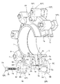
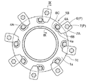
図1〜図3は流体配管系(管路)の途中のフランジ接合部を示し、流体管の一例である鋳鉄製の両水道管1、1の端部にそれぞれ径方向外方に円板状に延出形成された両フランジ部1A、1Bが、リング状でシート状のガスケット2を両フランジ部1A、1B間に介装させた状態で、複数の連結ボルト4A及び連結ナット4B(本実施形態では、8ヶずつ)により連結されている。両フランジ部1A、1Bには、フランジ接合方向(軸方向)に貫通する複数の貫通孔3(本実施形態では、8ヶ所ずつ)が周方向で等間隔に形成され、これら貫通孔3に連結ボルト4Aが挿通されて、当該連結ボルト4Aの雄ネジ部4bの先端側に連結ナット4Bが螺合固定される。なお、本実施形態の両フランジ部1A、1Bは、いわゆるRF形フランジである。
Hereinafter, based on FIGS. 1-10, embodiment of the flange junction part reinforcement jig | tool P is described.
1 to 3 show a flange joint part in the middle of a fluid piping system (pipe), and are formed in a disk shape radially outward at the ends of both
ここで、以下では、両フランジ部1A、1Bにおいて、それぞれ水道管1が突出する側の面を外側面1a、1aとし、両フランジ部1A、1Bが連結ボルト4A及び連結ナット4Bにより連結された際にフランジ接合方向(軸方向)で相互に対向する面を接合面1b、1bとし、さらに、両フランジ部の1A、1Bの径方向外方側の面を外周面1c、1cとして説明する。
Here, in the following, in both
図4〜図9に示すように、本願に係るフランジ接合部補強治具Pは、上述のようにボルト連結されている両フランジ部1A、1Bにおいて、フランジ部1Aの外側面1aに当接可能な押圧部5Cを備えた第1挟持部材5及びフランジ部1Bの外側面1aに当接可能な押圧部6Bを備えた第2挟持部材6と、これら第1挾持部材5の押圧部5C及び第2挟持部材6の押圧部6Bを両フランジ部1A、1Bの外側面1a、1aにそれぞれ当て付けた状態で、当該第1挾持部材5及び第2挟持部材6をフランジ接合方向(軸方向)に引き寄せて締付固定する締結手段7とを備える。
As shown in FIGS. 4 to 9, the flange joint reinforcing jig P according to the present application can abut on the
図4及び図6〜図9に示すように、第1挟持部材5は、金属材料により構成され、横断面視で外面5aが概略四角形状且つ内周面5bが円形状の概略有底角筒状(筒状の一例)に形成された内嵌合部5Aと、内嵌合部5Aの一端部において当該内嵌合部5Aの外面5aから全周に亘って外方側に延出する鍔状部5Bと、鍔状部5Bの四辺のうちの一辺からさらに外方側に延出する押圧部5Cとを一体的に備えて構成されている。
As shown in FIGS. 4 and 6 to 9, the
内嵌合部5Aは、側面視で概略正方形状に形成され(図4参照)、内嵌合部5A内には、後述する締結手段7の締結ボルト7Aの雄ネジ部7aを挿通可能な円筒状の筒状内部空間5cが形成されている。筒状内部空間5cの内径は、締結ボルト7Aの雄ネジ部7aの外径よりも若干大径に形成されている。
The inner
鍔状部5Bは、側面視で概略正方形状に形成され、横断面視で中央部に上記筒状内部空間5cが貫通形成されている(図4参照)。
The bowl-shaped
筒状内部空間5cにおいて、鍔状部5B及び押圧部5Cが形成された側は開口形成され、鍔状部5B及び押圧部5Cが形成された側とは反対側は、締結ボルト7Aの雄ネジ部7aが螺合可能な雌ネジ部5dが、内嵌合部5Aの底部を貫通する状態で開口形成されている。すなわち、雌ネジ部5dは、内嵌合部5Aにおける筒状内部空間5cの内周面5bにおいて、鍔状部5B及び押圧部5Cが形成された側とは反対側の端部に形成されている。
In the cylindrical
押圧部5Cは、側面視で若干先窄み形状に形成され(図4(a)参照)、縦断面視で先端側に行くにつれて雌ネジ部5d側に傾斜するテーパー形状に形成され、押圧部5Cのうち雌ネジ部5d側の面の先端部位が、内嵌合部5Aの外面5aと垂直な押圧面5eとして形成されている。
The
図5〜図9に示すように、第2挟持部材6は、金属部材により構成され、横断面視で外面6a及び内面6bが概略四角形状の概略有底角筒状(筒状の一例)に形成された外嵌合部6Aと、外嵌合部6Aの一端部において当該外嵌合部6Aの外面6aの四辺のうちの一辺から外方側に延出する押圧部6Bと、押圧部6Bの先端部から延出形成される脱落防止腕6Cとを一体的に備えて構成されている。
As shown in FIGS. 5 to 9, the
外嵌合部6Aは、側面視で概略正方形状に形成され(図5参照)、外嵌合部6A内には、第1挟持部材5の内嵌合部5Aを挿入可能な筒状内部空間6cが形成されている。筒状内部空間6cは横断面視で概略正方形状に形成され、横断面視で概略正方形状の内嵌合部5Aよりも若干大きく形成されている。このため、内嵌合部5Aの外面5aと外嵌合部6Aの内面6bとの嵌合形状は、内嵌合部5Aを外嵌合部6Aの筒状内部空間6cに挿入(嵌合)させると、挿入方向(筒状内部空間6cの長手方向)には摺動可能であるが、挿入方向周り(筒状内部空間6cの長手方向に沿った軸周り)での相対回転が不能となるように形成されている。
また、筒状内部空間6cにおいて、押圧部6Bが形成された側とは反対側は開口形成され、押圧部6Bが形成された側は、締結ボルト7Aの雄ネジ部7aを挿入可能で且つ頭部7bを挿通不能な挿通孔6dが、外嵌合部6Aの底部を貫通する状態で開口形成されている。なお、締結ボルト7Aの雄ネジ部7aが挿通孔6dに挿通された状態では、雄ネジ部7aの外周面と挿通孔6dの内周面との間には、所定の隙間が形成される(図9参照)。
6A of outer fitting parts are formed in a substantially square shape by side view (refer FIG. 5), and the cylindrical internal space which can insert the inner
Further, in the cylindrical
押圧部6Bは、上記第1挟持部材5の押圧部5Cと同様に、側面視で若干先窄み形状に形成され(図5(a)参照)、縦断面視で先端側に行くにつれて押圧部6Bが形成された側とは反対側に傾斜するテーパー形状に形成され、押圧部6Bのうち挿通孔6dとは反対側の面の先端部位が、外嵌合部6Aの外面6aと垂直な押圧面6eとして形成されている。
Similar to the
脱落防止腕6Cは、側面視で先窄み形状に形成された押圧部6Bの先端部から凹状に延出形成される概略U字形状部材であり(図5(a)、(c)参照)、連結ボルト4Aの頭部4aの少なくとも一部を囲うことができるように、頭部4aの外周よりも若干大径に形成されている。また、縦断面視で、脱落防止腕6Cを構成する面のうち、筒状内部空間6cの長手方向における挿通孔6dとは反対側の面は、押圧面6eよりも挿通孔6d側に引退形成されている。
The drop-
図6〜図9に示すように、締結手段7は、外嵌合部6Aの外側から挿通孔6dを介して筒状内部空間6c内に挿入される上述の締結ボルト7Aと、内嵌合部5Aの内周面5bに形成された雌ネジ部5dとから構成されている。
As shown in FIGS. 6 to 9, the fastening means 7 includes the above-described
次に、複数の連結ボルト4A及び連結ナット4Bにより連結された両フランジ部1A、1Bに、フランジ接合部補強治具Pを装着する作業工程について説明する。
Next, an operation process for mounting the flange joint reinforcing jig P on both
図6に示すように、フランジ接合方向で相対向する部位に形成されている第1挟持部材5の内嵌合部5A及び第2挟持部材6の外嵌合部6Aを、内嵌合部5Aの底部側(雌ネジ部5d側)から当該内嵌合部5Aが外嵌合部6Aの筒状内部空間6cに内嵌するように、両フランジ部1A、1Bの外周面1c、1cよりも径方向外方側の位置でフランジ接合方向から嵌合させる。
この際には、内嵌合部5Aの外面5aと外嵌合部6Aの内面6bとが横断面視で相対回転不能な概略正方形状に形成されているので、第1挟持部材5の押圧部5Cと第2挟持部材6の押圧部6Bとを同方向に延出させた所期の相対位置関係に位置決めした状態で、容易に嵌合させることができる。すなわち、第1挟持部材5の押圧部5Cの押圧面5eと第2挟持部材6の押圧部6Bの押圧面6eとが、フランジ接合方向で対向するように、内嵌合部5Aが外嵌合部6Aに嵌合される。
As shown in FIG. 6, the inner
At this time, since the
図7に示すように、内嵌合部5Aと外嵌合部6Aとが嵌合している状態において、縦断面視で第1挟持部材5の押圧部5Cと内嵌合部5Aの外面5aと第2挟持部材6の押圧部6Bと外嵌合部6Aの外面6aとにより概略U字形状の凹部Cが形成され、当該凹部Cを、両フランジ部1A、1Bにおける周方向におけるボルト連結箇所の隣接間部位に対して径方向外方から外嵌装着可能に構成されている。そのため、上述の内嵌合部5Aと外嵌合部6Aとの嵌合は、一旦、フランジ接合方向において、第1挟持部材5の押圧部5Cの押圧面5eと第2挟持部材6の押圧部6Bの押圧面6eとの間隔が、フランジ部1Aの外側面1aとフランジ部1Bの外側面1aとの間隔よりも大きくなる程度に行われる。
なお、上述の内嵌合部5Aと外嵌合部6Aとの嵌合は、フランジ接合方向における内嵌合部5Aと外嵌合部6Aとの重なり部位の大きさ(嵌合距離)を所定範囲内で任意に調整可能に構成され、この調整に伴って、第1挟持部材5の押圧部5Cの押圧面5eと第2挟持部材6の押圧部6Bの押圧面6eとの間隔を所定範囲内で任意に調整可能に構成されている。そのため、フランジ接合方向における内嵌合部5Aと外嵌合部6Aとの重なり部位の大きさ(嵌合距離)、及び、押圧面5eと押圧面6eとの間隔をそれぞれ適宜設定した状態で、後述する締結手段7により第1挟持部材5と第2挟持部材6とを締付固定することができる。
As shown in FIG. 7, in a state where the inner
The above-mentioned fitting between the inner
そして、凹部Cを両フランジ部1A、1Bのボルト連結箇所の隣接間部位に対して外嵌装着する際には、押圧部6Bが延出する側における外嵌合部6Aの外面6a(凹部Cの一部)を、両フランジ部1A、1Bの外周面1c、1cの少なくとも一方に当接させることで、第1挟持部材5及び第2挟持部材6を所期の設定外嵌装着位置に装着することができる(図7及び図9参照)。すなわち、押圧部6Bが延出する側における外嵌合部6Aの外面6aが、両フランジ部1A、1Bの外周面1c、1cとの当接によって設定外嵌装着位置に規制する装着規制部として機能することとなる。
When the concave portion C is externally fitted to adjacent portions of the bolt connecting portions of the
続いて、凹部Cを設定外嵌装着位置に装着した後、押圧部6Bが延出する側における外嵌合部6Aの外面6aを両フランジ部1A、1Bの外周面1c、1cの少なくとも一方に当接させた状態で、第1挟持部材5の押圧部5Cの押圧面5eがフランジ部1Aの外側面1aに当接し且つ第2挟持部材6の押圧部6Bの押圧面6eがフランジ部1Bの外側面1aに当接するまで、内嵌合部5A及び外嵌合部6Aをフランジ接合方向で引き寄せて内嵌合部5Aを外嵌合部6Aの筒状内部空間6cに嵌合させる(図7及び図9参照)。
Subsequently, after the concave portion C is mounted at the set external fitting mounting position, the
この際、第2挟持部材6に隣接する連結ボルト4Aの頭部4aに対してフランジ部1Bの径方向内方側から径方向外方側に回り込む凹状に形成されている第2挟持部材6の脱落防止腕6Cを、当該連結ボルト4Aの頭部4aに対して径方向内方側から当接或いは近接させた状態とする(図6及び図8参照)。この脱落防止腕6Cの延出方向は、締結ボルト7Aを締付側に回転させた際に当該脱落防止腕6Cが設けられている第2挾持部材6が共回りする方向と同方向に設定されている。すなわち、脱落防止腕6Cは、側面視で、第2挟持部材6の押圧部6Bの先端部から、外嵌合部6Aの中央部に形成された挿通孔6dを中心とする締結ボルト7Aの締付方向に向かって(本実施形態では、締結ボルト7Aは右ネジであるので、挿通孔6dを中心とする時計回り方向、つまり、挿通孔6dから押圧部6Bが延出する方向に対して押圧部6Bの右側方向に向かって)延出するように形成されている。
At this time, the
次に、締結ボルト7Aの雄ネジ部7aを、フランジ接合方向における外嵌合部6Aの外側から挿通孔6dを介して筒状内部空間6c内に挿入し、当該締結ボルト7Aの頭部7bが外嵌合部6Aの外側面(図示せず)に当接するまで、筒状内部空間6cに嵌合されている内嵌合部5Aの雌ネジ部5dに螺合させ締付固定する。この締結ボルト7Aの締付固定の際、仮に第2挟持部材6が締付方向に共回りしたとしても、脱落防止腕6Cが隣接する連結ボルト4Aの頭部4aに径方向内方側から当接することとなり、それ以上の共回りが阻止される。また、第2挟持部材6は、押圧部6B及びフランジ部1Bの外側面1a、脱落防止腕6Cと連結ボルト4Aの頭部4aにより支持されるので、締結ボルト7Aの締付作業を安定して行うことができる。
Next, the
なお、脱落防止腕6Cのフランジ部1Bの外側面1aに対面する側面が、当該脱落防止腕6Cが設けられている第2挾持部材6における押圧部6Bの押圧面6eよりもフランジ部1Bの外側面1aから離間する側に配置されているので、締結ボルト7Aを締付けて押圧部6Bの押圧面6eをフランジ部1Bの外側面1aに押圧した場合でも、脱落防止腕6Cがフランジ部1Bの外側面1aに当接せず、脱落防止腕6Cに直接荷重が掛かることがなく、脱落防止腕6Cの破損を防止することができる。
In addition, the side surface facing the
従って、両押圧部5C、6Bをそれぞれ両フランジ部1A,1Bの外側面1a、1aに当て付けた状態で第1挟持部材5及び第2挟持部材6をフランジ接合方向に引き寄せて、内嵌合部5Aが外嵌合部6A内に嵌合し、内嵌合部5Aと外嵌合部6Aとがフランジ接合方向(軸方向)で重なった状態で、締付固定することができるとともに、この締付固定された状態では、押圧部6Bが延出する側における外嵌合部6Aの外面6aが、両フランジ部1A、1Bの外周面1c、1cの少なくとも一方に当接した状態となる。
また、締付固定した状態では、内嵌合部5Aの雌ネジ部5dが、締結ボルト7Aの頭部7bに近接した位置に位置することから、雌ネジ部5dと締結ボルト7Aの雄ネジ部7aとの螺合箇所が、締結ボルト7Aの頭部7bが外嵌合部6Aの外側面と当接する位置に近接することとなり、フランジ接合方向(軸方向)における締結ボルト7Aの頭部7bと当該螺合箇所との距離を比較的小さくすることができる。これにより、両フランジ部1A,1Bに曲げ方向(径方向)或いは引張方向(軸方向)の力が作用した場合でも、締結ボルト7Aの伸びや破壊を良好に防止することができ、両フランジ部1A,1Bの離間やずれ及びこれらに伴う流体の漏洩を良好に防止することができる。さらに、雌ネジ部5dを筒状内部空間5c、6c内における内嵌合部5Aと外嵌合部6Aとの重なり部位に位置させることができ、締結ボルト7Aの長さを比較的短くすることが可能となり、締結ボルト7Aの先端が筒状内部空間5c、6cの外部に突出することを良好に防止することができ、フランジ接合部補強治具Pの外観を損なうことなく省スペース化を図ることができる。
Therefore, the
Further, in the tightened and fixed state, the
次に、上記フランジ接合部補強治具Pを装着後、両フランジ部1A、1Bにおける、その他の全てのボルト連結箇所の隣接間部位に対して、別のフランジ接合部補強治具Pを径方向外方から順次外嵌装着する。なお、当該外嵌装着は、必要に応じて、ボルト連結箇所の隣接間部位の一部に対してのみ行うこととしてもよい。
Next, after mounting the flange joint reinforcement jig P, another flange joint reinforcement jig P is radially attached to the adjacent portions of all other bolt connection locations in the
これにより、第1挟持部材5及び第2挟持部材6が締結手段7により締付固定された状態で、両フランジ部1A、1Bに曲げ方向(径方向)への力が作用した場合でも、締結手段7の締結部位に加えて、内嵌合部5Aと外嵌合部6Aとの重なり部位でも当該力を受け止めることができ、締結手段7の締結部位に掛かる応力の低減を図ることができる。また、第1挟持部材5及び第2挟持部材6が締結手段7により締付固定された状態では、内嵌合部5Aが内嵌された外嵌合部6Aの外面が両フランジ部1A、1Bの外周面1c、1cの少なくとも一方に当接しているので、両フランジ部1A、1Bに曲げ方向(径方向)の力が作用した場合には、当該外嵌合部6Aの外面6aと両フランジ部1A、1Bの外周面1c、1cとの当接箇所でも当該力を受け止めることができ、締結手段7、内嵌合部5Aと外嵌合部6Aとの重なり部位に掛かる応力の低減を図ることができる。さらに、締結ボルト7Aの雄ネジ部7aが挿通孔6dに挿通された状態では、雄ネジ部7aの外周面と挿通孔6dの内周面との間に所定の隙間が形成されるので、両フランジ部1A、1Bに曲げ方向(径方向)への力が作用して、万が一、締結ボルト7Aが径方向に若干変位した場合でも、当該所定の隙間程度の変位であれば、締結ボルト7Aの雄ネジ部7aが挿通孔6dに当接することがなく、締結ボルト7Aの伸びや破壊を防止することができる。
Thus, even when a force in the bending direction (radial direction) acts on both
従って、フランジ接合部補強治具Pを、両フランジ部1A、1Bに容易に装着できるとともに、フランジ接合部補強治具Pによる両フランジ部1A、1Bの接合強度をより向上させて、両フランジ部1A、1Bの離間やずれ及びこれらに伴う上水(流体の一例)の漏洩をより確実に防止することができ、管路の耐震性能の向上をも図ることができる。
よって、両フランジ部1A、1Bを含む管路を所定の耐震性能(離脱防止力が3DkN以上(Dは呼び径))を備えた耐震管路に補強しつつ、両フランジ部1A、1Bの離間やずれを簡便且つ安価に防止することができる。
Accordingly, the flange joint reinforcing jig P can be easily attached to both the
Therefore, the
また、フランジ接合部補強治具Pは、筒状に構成された外嵌合部6A内に内嵌合部5Aが嵌合し、さらに、内嵌合部5A内の筒状内部空間5cに締結手段7の締結ボルト7Aが挿通されるので、両フランジ部1A、1Bの外周面1c、1cの径方向外方側位置にある内嵌合部5A及び外嵌合部6Aの配設箇所と、締結ボルト7Aの配設箇所とを兼用することができる。これにより、両フランジ部1A、1Bに装着されたフランジ接合部補強治具P及び締結ボルト7Aのフランジ接合方向(軸方向)での寸法、及び、当該フランジ接合部補強治具Pの径方向外方側(径方向)での寸法の何れをも小さくすることができ、省スペース化を図ることができる。
Further, the flange joint reinforcing jig P has an inner
さらに、自重或いは地震等により、両フランジ部1A、1Bに歪みや変形或いは相対的なずれ等が生じた場合でも、凹状に形成された脱落防止腕6Cが、連結ボルト4Aの頭部4aに確実に当接し、当接状態を維持することができ、フランジ接合部補強治具Pが両フランジ部1A、1Bから脱落することをより確実に防止することができる。また同様に、フランジ接合部補強治具Pが両フランジ部1A、1Bの周方向の何れの箇所に設けられた場合でも、当該フランジ接合部補強治具Pが両フランジ部から下方側に脱落することを防止することができる。
Further, even when the
ここで、上述のとおり、フランジ接合部補強治具Pは、第1挟持部材5の内嵌合部5Aと第2挟持部材6の外嵌合部6Aとのフランジ接合方向(軸方向)における重なり部位の大きさ(嵌合距離)を所定範囲内で任意に調整することで、第1挟持部材5の押圧部5Cの押圧面5eと第2挟持部材6の押圧部6Bの押圧面6eとの間隔を所定範囲内で任意に調整可能に構成されている。
このため、両フランジ部1A、1Bの呼び径や設計圧力に応じて、両フランジ部1A、1Bの肉厚が変更される場合、例えば、図10に示すように、両フランジ部1A、1Bの肉厚よりも薄い肉厚の両フランジ部10A、10Bにフランジ接合部補強治具Pを装着する場合であっても、内嵌合部5Aと外嵌合部6Aとの重なり部位の大きさ(嵌合距離)を調整(図10では、嵌合距離を大きく調整)することで、第1挟持部材5の押圧部5Cの押圧面5eをフランジ部10Aの外側面10aに当接させ且つ第2挟持部材6の押圧部6Bの押圧面6eをフランジ部10Bの外側面10aに当接させた状態で、内嵌合部5Aの雌ネジ部5dに締結ボルト7Aの雄ネジ部7aを螺合させて内嵌合部5A及び外嵌合部6A、ひいては、第1挟持部材5及び第2挟持部材6を両フランジ部10A、10Bに良好に締付固定することができる。
Here, as described above, the flange joint reinforcing jig P is overlapped in the flange joining direction (axial direction) between the inner
For this reason, when the thickness of both
このように、フランジ部1A、1Bの呼び径や設計圧力に応じて各フランジ部1A、1Bの肉厚を変更した場合でも、締結手段7が、内嵌合部5Aと外嵌合部6Aとの筒状内部空間5c、6cに対して外嵌合部6Aの外側から挿通孔6dを介して挿入される締結ボルト7Aと、内嵌合部5Aの内周面5bに形成された締結ボルト7Aが螺合する雌ネジ部5dとから構成され、雌ネジ部5dを筒状内部空間5c、6c内における内嵌合部5Aと外嵌合部6Aとの重なり部位の外嵌合部6A側の一端部に位置させるので、雌ネジ部5dと締結ボルト7Aの雄ネジ部7aとの螺合箇所が、締結ボルト7Aの頭部7bが外嵌合部6Aと当接する位置に近接することとなり、フランジ接合方向(軸方向)における締結ボルト7Aの頭部7bと当該螺合箇所との距離を比較的小さくすることができ、両フランジ部1A、1Bに曲げ方向(径方向)或いは引張方向(軸方向)の力が作用した場合でも、締結ボルト7Aの伸びや破壊を良好に防止することができる。また、当該距離を比較的小さくすることができれば、締結ボルト7Aとして汎用のボルトを使用することが可能となり、フランジ接合部補強治具Pを安価のものとすることができる。
Thus, even when the thickness of each
〔別実施形態〕
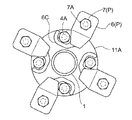
(A)上記実施形態では、両フランジ部1A、1Bを8対の連結ボルト4A及び連結ナット4Bにより連結する構成としたが、フランジ部1A、1Bの呼び径や設計圧力等に応じて、連結ボルト4A及び連結ナット4Bの数は適宜調整することができる。例えば、図11に示すように、両フランジ部11A、11Bを4対の連結ボルト4A及び連結ナット4Bにより連結する構成として、ボルト連結箇所の隣接間部位にフランジ接合部補強治具Pを装着する構成とすることもできる。
[Another embodiment]
(A) In the above embodiment, the two
(B)上記実施形態では、両フランジ部1A、1Bにフランジ接合部補強治具Pを装着する際、第1挟持部材5の内嵌合部5Aと第2挟持部材6の外嵌合部6Aとをある程度嵌合させてから、内嵌合部5Aと押圧部5Cと外嵌合部6Aと押圧部6Bとにより形成される凹部Cを両フランジ部1A、1Bに外嵌装着する構成としたが、フランジ接合部補強治具Pの装着手順は適宜変更することができる。
例えば、第2挟持部材6の押圧部6Bをフランジ部1Bの外側面1aに当接させ、脱落防止腕6Cをフランジ部1Bの径方向内方側から連結ボルト4Aの頭部4aに当接又は近接させ、さらに、外嵌合部6Aをフランジ部1Bの外周面1cの径方向外方側に位置させた状態で、第1挟持部材5の内嵌合部5Aをフランジ接合方向から上記外嵌合部6A内に嵌合させつつ、押圧部5Cをフランジ部1Aの外側面1aに当接させる。その後、締結ボルト7Aの雄ネジ部7aを外嵌合部6Aの挿通孔6dを介して内嵌合部5Aの雌ネジ部5dに螺合させ、第1挟持部材5及び第2挟持部材6を両連結フランジ部1A、1Bに外嵌装着することもできる。
また、例えば、上記実施形態と同様に、両フランジ部1A、1Bにフランジ接合部補強治具Pを装着する際、第1挟持部材5の内嵌合部5Aと第2挟持部材6の外嵌合部6Aとをある程度嵌合させた際に、締結ボルト7Aの雄ネジ部7aを外嵌合部6Aの挿通孔6dを介して内嵌合部5Aの雌ネジ部5dにある程度螺合させてから、第1挟持部材5及び第2挟持部材6の凹部Cを両連結フランジ部1A、1Bに外嵌装着し、その後、締結ボルト7Aを本締めする構成としてもよい。
(B) In the above embodiment, when the flange joint reinforcing jig P is attached to both
For example, the
Further, for example, as in the above embodiment, when the flange joint reinforcing jig P is attached to both
(C)上記実施形態では、脱落防止腕6Cを第2挟持部材6にのみ設ける構成としたが、必要に応じて、第1挟持部材5及び第2挟持部材の両方又は一方に設ける構成とすることもでき、この場合、脱落防止腕6Cを、連結ボルト4Aの頭部4a又は連結ナット4Bに対して両フランジ1A、1Bの径方向内方側から当接又は近接させる構成とすることができる。
また、脱落防止腕6Cを、連結ボルト4Aの頭部4a又は連結ナット4Bに対して、両フランジ1A、1Bの径方向内方側から径方向外方側に回り込む凹状に形成せずに、単に、連結ボルト4Aの頭部4a又は連結ナット4Bに対して、両フランジ1A、1Bの径方向内方側から当接する棒状部材で構成することもできる。
なお、脱落防止腕6Cを省略する構成とすることもできる。
(C) In the above embodiment, the drop-
Further, the drop-
Note that the drop-off preventing
(D)上記実施形態では、第1挟持部材5に内嵌合部5Aを設け、第2挟持部材6に外嵌合部6Aを設けるように構成したが、第1挟持部材5に外嵌合部を設け、第2挟持部材6に内嵌合部を設ける構成としてもよい。
(D) In the above embodiment, the first holding
(E)上記実施形態では、第1挟持部材5の内嵌合部5Aと第2挟持部材6の外嵌合部6Aとの嵌合形状、すなわち、横断面視で、内嵌合部5Aの外面5a及び外嵌合部6Aの内面6bの形状を、概略正方形状としたが、内嵌合部5Aと外嵌合部6Aとが嵌合された状態でフランジ接合方向周りでの相対回転が不能に構成されていれば、その他の嵌合形状を採用することもできる。例えば、横断面視で、内嵌合部5Aの外面5a及び外嵌合部6Aの内面6bの形状を、楕円形状、多角形状等に構成することができる。
(E) In the above embodiment, the fitting shape between the inner
(F)上記実施形態では、第1挟持部材5の内嵌合部5Aを有底筒状に構成し内部に筒状内部空間5cを形成して、内嵌合部5Aの底部に雌ネジ部5dを開口形成するとともに、第2挟持部材6の外嵌合部6Aを有底筒状に構成し内部に筒状内部空間6cを形成して、外嵌合部6Aの底部に挿通孔6dを形成することで、締結手段7を、当該挿通孔6dに挿通され且つ雌ネジ部5dに螺合される締結ボルト7Aと当該雌ネジ部5dとにより構成したが、第1挟持部材5、第2挟持部材6及び締結手段7の構成は、適宜変更することができる。
(F) In the above embodiment, the inner
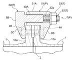
例えば、図12に示すように、第1挟持部材50の内嵌合部50Aを第2挟持部材51の外嵌合部51Aに内嵌可能な外径を備えた概略角棒状に構成し、第2挟持部材51の外嵌合部51Aを筒状に構成する。なお、第1挟持部材50は、上記実施形態における鍔状部5B及び押圧部5Cを備え、第2挟持部材51は、上記実施形態における押圧部6Bを備える。そして、内嵌合部50Aの先端側には、雄ネジ部52aを備えたボルト52がフランジ接合方向(内嵌合部50Aの長手方向)に突出形成され、外嵌合部51A内に内嵌合部50Aが相対回転不能に嵌合した状態で、雄ネジ部52aの先端が外嵌合部51Aの外側に突出し、当該突出部分に締結ナット53が外嵌合部51Aの外方から外面側に当接するまで螺合され、第1挟持部材50及び第2挟持部材51が締付固定される構成としてもよい。
For example, as shown in FIG. 12, the inner
また、例えば、図13に示すように、第1挟持部材60の内嵌合部60Aを筒状に構成して、当該内嵌合部60Aを相対回転不能な状態で第2挟持部材61の外嵌合部61Aに内嵌可能な外径を備え且つ締結ボルト62の雄ネジ部(図示せず)を挿通可能な筒状内部空間63を形成可能な内径を備えた構成とする。すなわち、内嵌合部60Aには、雌ネジ部を形成しない。なお、第1挟持部材60は、上記実施形態における鍔状部5B及び押圧部5Cを備え、第2挟持部材61は、上記実施形態における押圧部6B(挿通孔6d)を備える。そして、締結手段7が、内嵌合部60Aと外嵌合部61Aとの筒状内部空間63、6cに対して一方の外側から貫通状態で挿入される締結ボルト62と、締結ボルト62の突出雄ネジ部62aに他方の外側から螺合する締結ナット64とを備える。そして、外嵌合部61A内に内嵌合部60Aが嵌合した状態で、突出雄ネジ部62aが外嵌合部61Aの外側に突出し、当該突出雄ネジ部62aに締結ナット64が外嵌合部61Aの外方から外面側に当接するまで螺合され、第1挟持部材60及び第2挟持部材61が締付固定される構成としてもよい。
これにより、内嵌合部60A及び外嵌合部61Aを筒状に形成するだけで、両者にネジ山を形成する必要がないため、フランジ接合部補強治具Pを簡便且つ安価な構成とすることができる。
Further, for example, as shown in FIG. 13, the inner
Accordingly, the inner
(G)上記実施形態では、第1挟持部材5の内嵌合部5Aを有底筒状に構成し内部に筒状内部空間5cを形成して、当該筒状内部空間5cにおいて、鍔状部5B及び押圧部5Cが形成された側を開口形成したが、当該開口形成された部位をゴム等により構成される栓部材により閉塞する構成とすることもできる。これにより、筒状内部空間5c内に塵埃等が侵入することを良好に防止できるとともに、外観の向上も図ることができる。
(G) In the above-described embodiment, the inner
(H)上記実施形態では、両フランジ部1A、1Bを、いわゆるRF形フランジとした構成について説明したが、フランジ接合であれば、その他のフランジ接合であってもよく、例えば、いわゆるGF形フランジとしてもよい。
(H) In the above embodiment, the configuration in which both
(I)上記実施形態では、流体配管系(管路)を構成する流体管の一例である鋳鉄製の両水道管1、1に形成した両フランジ部1A、1Bにフランジ接合部補強治具Pを装着する例について説明したが、流体管としては気体や液体が通流する管であってもよい。
(I) In the above embodiment, the flange joint reinforcing jig P is connected to the
以上説明したように、両フランジ部を含む管路を所定の耐震性能を備えた耐震管路に補強しつつ、両フランジ部の離間やずれを簡便且つ安価に防止できるフランジ接合部補強治具を提供することができる。 As described above, a flange joint reinforcement jig that can easily and inexpensively prevent separation and displacement of both flange portions while reinforcing a pipeline including both flange portions to an earthquake resistant pipeline having predetermined earthquake resistance performance. Can be provided.
1 水道管(流体管)
1A フランジ部
1B フランジ部
1a 外側面
1c 外周面
4A 連結ボルト
4a 頭部
4B 連結ナット
5 第1挟持部材(挟持部材)
5A 内嵌合部
5C 押圧部
5a 外面
5b 内周面
5c 筒状内部空間
5d 雌ネジ部(締結手段)
5e 押圧面
6 第2挟持部材(挟持部材)
6A 外嵌合部
6B 押圧部
6C 脱落防止腕
6a 外面(装着規制部)
6b 内面
6c 筒状内部空間
6d 挿通孔
6e 押圧面
7 締結手段
7A 締結ボルト(締結手段)
7a 雄ネジ部
62 締結ボルト(締結手段)
62a 突出雄ネジ部
64 締結ナット(締結手段)
P フランジ接合部補強治具
C 凹部
1 Water pipe (fluid pipe)
5A Inner
6A Outer
7a
62a Projecting
P Flange joint reinforcement jig C Recess
Claims (11)
前記両挾持部材のフランジ接合方向で相対向する部位に、前記両フランジ部の外周面よりも径方向外方側位置においてフランジ接合方向から嵌合する内嵌合部と外嵌合部とが形成されているフランジ接合部補強治具。 A pair of clamping members each having a pressing part that can be brought into contact with the outer side surfaces of both flange parts connected to the bolts, and the pressing parts of the both holding members applied to the outer side surfaces of both flange parts. A flange joint reinforcement jig comprising fastening means for pulling both clamping members in the flange joining direction and fastening them together,
An inner fitting portion and an outer fitting portion that are fitted from the flange joining direction at a radially outer side position than the outer peripheral surface of the both flange portions are formed at portions facing each other in the flange joining direction of the both holding members. The flange joint reinforcement jig.
Priority Applications (1)
| Application Number | Priority Date | Filing Date | Title |
|---|---|---|---|
| JP2013009609A JP6142427B2 (en) | 2013-01-22 | 2013-01-22 | Flange joint reinforcement jig |
Applications Claiming Priority (1)
| Application Number | Priority Date | Filing Date | Title |
|---|---|---|---|
| JP2013009609A JP6142427B2 (en) | 2013-01-22 | 2013-01-22 | Flange joint reinforcement jig |
Publications (2)
| Publication Number | Publication Date |
|---|---|
| JP2014141995A true JP2014141995A (en) | 2014-08-07 |
| JP6142427B2 JP6142427B2 (en) | 2017-06-07 |
Family
ID=51423454
Family Applications (1)
| Application Number | Title | Priority Date | Filing Date |
|---|---|---|---|
| JP2013009609A Active JP6142427B2 (en) | 2013-01-22 | 2013-01-22 | Flange joint reinforcement jig |
Country Status (1)
| Country | Link |
|---|---|
| JP (1) | JP6142427B2 (en) |
Cited By (16)
| Publication number | Priority date | Publication date | Assignee | Title |
|---|---|---|---|---|
| JP2016125599A (en) * | 2015-01-05 | 2016-07-11 | 岡山市 | Reinforcement jig of joint part |
| JP2016138515A (en) * | 2015-01-28 | 2016-08-04 | 愛三工業株式会社 | Fastening structure for throttle body |
| JP2016180452A (en) * | 2015-03-24 | 2016-10-13 | コスモ工機株式会社 | Flange reinforcement |
| JP2017145885A (en) * | 2016-02-17 | 2017-08-24 | 岡山市 | Reinforcement jig for junction and reinforcement structure for junction |
| JP2018204779A (en) * | 2017-06-09 | 2018-12-27 | 岡山市 | Reinforcement jig for connection part |
| JP2019095069A (en) * | 2019-03-13 | 2019-06-20 | 岡山市 | Connection part reinforcement structure and reinforcement jig for connection part |
| JP2019116957A (en) * | 2017-12-27 | 2019-07-18 | 岡山市 | Reinforcement jig of joint part |
| CN110625321A (en) * | 2019-10-24 | 2019-12-31 | 浙江佰通防腐设备有限公司 | A valve elbow flange hole alignment device |
| JP2020034042A (en) * | 2018-08-28 | 2020-03-05 | 岡山市 | Flange reinforcement jig and attachment method of the same |
| JP2020101289A (en) * | 2016-02-17 | 2020-07-02 | 岡山市 | Reinforcement jig attachment method |
| JP2020180705A (en) * | 2019-03-13 | 2020-11-05 | 岡山市 | Joint portion reinforcing structure |
| CN112082019A (en) * | 2020-09-02 | 2020-12-15 | 江苏长隆石化装备有限公司 | Efficient quick connection device and method |
| JP2021050826A (en) * | 2021-01-18 | 2021-04-01 | コスモ工機株式会社 | Flange reinforcement tool |
| JP2021181829A (en) * | 2020-07-28 | 2021-11-25 | 岡山市 | Junction reinforcement structure |
| JP2022008994A (en) * | 2017-12-26 | 2022-01-14 | コスモ工機株式会社 | How to install the flange separation prevention device |
| JP2023159188A (en) * | 2019-10-21 | 2023-10-31 | コスモ工機株式会社 | How to install flange reinforcement |
Citations (9)
| Publication number | Priority date | Publication date | Assignee | Title |
|---|---|---|---|---|
| DE1079400B (en) * | 1956-01-23 | 1960-04-07 | Walter Gottlob Rathmann | Clamp connection for pipe flanges, especially on enamelled containers or devices |
| DE1196449B (en) * | 1960-12-29 | 1965-07-08 | Von Roll Ag | Clamp screw for connecting pipe flanges |
| US3771819A (en) * | 1971-12-01 | 1973-11-13 | Hydrasearch Co Inc | Axially and rotatably movable flange connector |
| JPS60190412U (en) * | 1984-05-28 | 1985-12-17 | 小柳機工株式会社 | Chain tensioner for automobile frame modification |
| JP2004316767A (en) * | 2003-04-16 | 2004-11-11 | Tokyo Gas Co Ltd | Flange joint security jig, pit valve security jig, and security method using these jigs |
| JP2005233210A (en) * | 2004-02-17 | 2005-09-02 | Cosmo Koki Co Ltd | Flange jointing device |
| JP2006329340A (en) * | 2005-05-26 | 2006-12-07 | Jfe Engineering Kk | Flange reinforcing jig and method of reinforcing flange joint |
| JP2007522391A (en) * | 2003-12-30 | 2007-08-09 | エフエムセ テクノロジーズ ソシエテ アノニム | Coupling that directly transmits the rotational motion of the operating bolt to the clamp jaw that is translated by the operating bolt |
| US20090295155A1 (en) * | 2008-01-10 | 2009-12-03 | Keller-Staub Pieriono | Flange connection |
-
2013
- 2013-01-22 JP JP2013009609A patent/JP6142427B2/en active Active
Patent Citations (9)
| Publication number | Priority date | Publication date | Assignee | Title |
|---|---|---|---|---|
| DE1079400B (en) * | 1956-01-23 | 1960-04-07 | Walter Gottlob Rathmann | Clamp connection for pipe flanges, especially on enamelled containers or devices |
| DE1196449B (en) * | 1960-12-29 | 1965-07-08 | Von Roll Ag | Clamp screw for connecting pipe flanges |
| US3771819A (en) * | 1971-12-01 | 1973-11-13 | Hydrasearch Co Inc | Axially and rotatably movable flange connector |
| JPS60190412U (en) * | 1984-05-28 | 1985-12-17 | 小柳機工株式会社 | Chain tensioner for automobile frame modification |
| JP2004316767A (en) * | 2003-04-16 | 2004-11-11 | Tokyo Gas Co Ltd | Flange joint security jig, pit valve security jig, and security method using these jigs |
| JP2007522391A (en) * | 2003-12-30 | 2007-08-09 | エフエムセ テクノロジーズ ソシエテ アノニム | Coupling that directly transmits the rotational motion of the operating bolt to the clamp jaw that is translated by the operating bolt |
| JP2005233210A (en) * | 2004-02-17 | 2005-09-02 | Cosmo Koki Co Ltd | Flange jointing device |
| JP2006329340A (en) * | 2005-05-26 | 2006-12-07 | Jfe Engineering Kk | Flange reinforcing jig and method of reinforcing flange joint |
| US20090295155A1 (en) * | 2008-01-10 | 2009-12-03 | Keller-Staub Pieriono | Flange connection |
Cited By (24)
| Publication number | Priority date | Publication date | Assignee | Title |
|---|---|---|---|---|
| JP2016125599A (en) * | 2015-01-05 | 2016-07-11 | 岡山市 | Reinforcement jig of joint part |
| JP2016138515A (en) * | 2015-01-28 | 2016-08-04 | 愛三工業株式会社 | Fastening structure for throttle body |
| JP2016180452A (en) * | 2015-03-24 | 2016-10-13 | コスモ工機株式会社 | Flange reinforcement |
| JP2017145885A (en) * | 2016-02-17 | 2017-08-24 | 岡山市 | Reinforcement jig for junction and reinforcement structure for junction |
| JP2020101289A (en) * | 2016-02-17 | 2020-07-02 | 岡山市 | Reinforcement jig attachment method |
| JP2018204779A (en) * | 2017-06-09 | 2018-12-27 | 岡山市 | Reinforcement jig for connection part |
| JP7161018B2 (en) | 2017-12-26 | 2022-10-25 | コスモ工機株式会社 | How to install the flange separation prevention device |
| JP2022008994A (en) * | 2017-12-26 | 2022-01-14 | コスモ工機株式会社 | How to install the flange separation prevention device |
| JP2019116957A (en) * | 2017-12-27 | 2019-07-18 | 岡山市 | Reinforcement jig of joint part |
| JP6995311B2 (en) | 2017-12-27 | 2022-01-14 | 岡山市 | Joint reinforcement jig |
| JP2020034042A (en) * | 2018-08-28 | 2020-03-05 | 岡山市 | Flange reinforcement jig and attachment method of the same |
| JP7142876B2 (en) | 2018-08-28 | 2022-09-28 | 岡山市 | Flange reinforcing jig and its mounting method |
| JP2020180705A (en) * | 2019-03-13 | 2020-11-05 | 岡山市 | Joint portion reinforcing structure |
| JP2019095069A (en) * | 2019-03-13 | 2019-06-20 | 岡山市 | Connection part reinforcement structure and reinforcement jig for connection part |
| JP7546737B2 (en) | 2019-10-21 | 2024-09-06 | コスモ工機株式会社 | How to install flange reinforcement |
| JP2023159188A (en) * | 2019-10-21 | 2023-10-31 | コスモ工機株式会社 | How to install flange reinforcement |
| CN110625321A (en) * | 2019-10-24 | 2019-12-31 | 浙江佰通防腐设备有限公司 | A valve elbow flange hole alignment device |
| JP2022136239A (en) * | 2020-07-28 | 2022-09-15 | 岡山市 | Joint part reinforcing structure |
| JP7123325B2 (en) | 2020-07-28 | 2022-08-23 | 岡山市 | Joint reinforcement structure |
| JP2021181829A (en) * | 2020-07-28 | 2021-11-25 | 岡山市 | Junction reinforcement structure |
| JP7355898B2 (en) | 2020-07-28 | 2023-10-03 | 岡山市 | Joint reinforcement structure |
| CN112082019A (en) * | 2020-09-02 | 2020-12-15 | 江苏长隆石化装备有限公司 | Efficient quick connection device and method |
| JP7085033B2 (en) | 2021-01-18 | 2022-06-15 | コスモ工機株式会社 | Flange reinforcement |
| JP2021050826A (en) * | 2021-01-18 | 2021-04-01 | コスモ工機株式会社 | Flange reinforcement tool |
Also Published As
| Publication number | Publication date |
|---|---|
| JP6142427B2 (en) | 2017-06-07 |
Similar Documents
| Publication | Publication Date | Title |
|---|---|---|
| JP6142427B2 (en) | Flange joint reinforcement jig | |
| WO2015170407A1 (en) | Flange coupling part reinforcing jig | |
| JP6374250B2 (en) | Joining reinforcement jig | |
| EP2463567B1 (en) | Pipe clamp assembly with tightening element bushing | |
| JP5722046B2 (en) | Single bolt band clamp with center rib with gasket and pipe lap joint using the same | |
| KR101631852B1 (en) | Flange joint connection structure | |
| JP2009513914A (en) | Fitting with angled cavity | |
| JP5361240B2 (en) | Flange coupling bolt | |
| JP6525057B2 (en) | Method of connecting pressure piping and method of creating pressure piping with flange | |
| US20160258560A1 (en) | Joint for high-pressure pipes and joint structure | |
| KR20180096464A (en) | Connector for piping that can be connected at any direction and angle | |
| JP6262544B2 (en) | Flange joint reinforcing structure and annular protective member used therefor | |
| JP6133762B2 (en) | Flange joint reinforcement jig | |
| KR101366184B1 (en) | Non-welded pipe joint using flanges with fixing ring | |
| JP6935888B2 (en) | How to install the reinforcement jig | |
| JP5917198B2 (en) | Telescopic flexible joint and water faucet with saddle using the same | |
| JP6964879B2 (en) | Leakage repair structure and leak repair tool | |
| JP3217571U (en) | Housing type pipe fitting | |
| KR200459679Y1 (en) | Tube connection joint | |
| JP6914302B2 (en) | Pipe fitting | |
| JP7264705B2 (en) | pipe fittings with loose flange | |
| JP2021175921A (en) | Reinforcement jig attachment method | |
| JP3140550U (en) | Pipe system | |
| KR20210046188A (en) | Welding Zero 2 track O-ring LEE Joint Polygon Flange | |
| HK1230696A1 (en) | Flange coupling part reinforcing jig |
Legal Events
| Date | Code | Title | Description |
|---|---|---|---|
| A711 | Notification of change in applicant |
Free format text: JAPANESE INTERMEDIATE CODE: A711 Effective date: 20150610 |
|
| A521 | Request for written amendment filed |
Free format text: JAPANESE INTERMEDIATE CODE: A821 Effective date: 20150610 |
|
| A621 | Written request for application examination |
Free format text: JAPANESE INTERMEDIATE CODE: A621 Effective date: 20151210 |
|
| A977 | Report on retrieval |
Free format text: JAPANESE INTERMEDIATE CODE: A971007 Effective date: 20161026 |
|
| A131 | Notification of reasons for refusal |
Free format text: JAPANESE INTERMEDIATE CODE: A131 Effective date: 20161122 |
|
| A521 | Request for written amendment filed |
Free format text: JAPANESE INTERMEDIATE CODE: A523 Effective date: 20170113 |
|
| TRDD | Decision of grant or rejection written | ||
| A01 | Written decision to grant a patent or to grant a registration (utility model) |
Free format text: JAPANESE INTERMEDIATE CODE: A01 Effective date: 20170411 |
|
| A61 | First payment of annual fees (during grant procedure) |
Free format text: JAPANESE INTERMEDIATE CODE: A61 Effective date: 20170420 |
|
| R150 | Certificate of patent or registration of utility model |
Ref document number: 6142427 Country of ref document: JP Free format text: JAPANESE INTERMEDIATE CODE: R150 |
|
| R250 | Receipt of annual fees |
Free format text: JAPANESE INTERMEDIATE CODE: R250 |
|
| R250 | Receipt of annual fees |
Free format text: JAPANESE INTERMEDIATE CODE: R250 |
|
| R250 | Receipt of annual fees |
Free format text: JAPANESE INTERMEDIATE CODE: R250 |
|
| R250 | Receipt of annual fees |
Free format text: JAPANESE INTERMEDIATE CODE: R250 |
|
| R250 | Receipt of annual fees |
Free format text: JAPANESE INTERMEDIATE CODE: R250 |
|
| R250 | Receipt of annual fees |
Free format text: JAPANESE INTERMEDIATE CODE: R250 |
|
| R250 | Receipt of annual fees |
Free format text: JAPANESE INTERMEDIATE CODE: R250 |