JP2014149305A - 自動分析装置 - Google Patents
自動分析装置 Download PDFInfo
- Publication number
- JP2014149305A JP2014149305A JP2014081060A JP2014081060A JP2014149305A JP 2014149305 A JP2014149305 A JP 2014149305A JP 2014081060 A JP2014081060 A JP 2014081060A JP 2014081060 A JP2014081060 A JP 2014081060A JP 2014149305 A JP2014149305 A JP 2014149305A
- Authority
- JP
- Japan
- Prior art keywords
- light
- automatic analyzer
- optical system
- optical transmission
- entrance
- Prior art date
- Legal status (The legal status is an assumption and is not a legal conclusion. Google has not performed a legal analysis and makes no representation as to the accuracy of the status listed.)
- Granted
Links
Images





Classifications
-
- G—PHYSICS
- G01—MEASURING; TESTING
- G01N—INVESTIGATING OR ANALYSING MATERIALS BY DETERMINING THEIR CHEMICAL OR PHYSICAL PROPERTIES
- G01N21/00—Investigating or analysing materials by the use of optical means, i.e. using sub-millimetre waves, infrared, visible or ultraviolet light
- G01N21/75—Systems in which material is subjected to a chemical reaction, the progress or the result of the reaction being investigated
- G01N21/76—Chemiluminescence; Bioluminescence
-
- G—PHYSICS
- G01—MEASURING; TESTING
- G01N—INVESTIGATING OR ANALYSING MATERIALS BY DETERMINING THEIR CHEMICAL OR PHYSICAL PROPERTIES
- G01N21/00—Investigating or analysing materials by the use of optical means, i.e. using sub-millimetre waves, infrared, visible or ultraviolet light
- G01N21/01—Arrangements or apparatus for facilitating the optical investigation
- G01N21/03—Cuvette constructions
- G01N21/0303—Optical path conditioning in cuvettes, e.g. windows; adapted optical elements or systems; path modifying or adjustment
-
- G—PHYSICS
- G02—OPTICS
- G02B—OPTICAL ELEMENTS, SYSTEMS OR APPARATUS
- G02B6/00—Light guides; Structural details of arrangements comprising light guides and other optical elements, e.g. couplings
- G02B6/0001—Light guides; Structural details of arrangements comprising light guides and other optical elements, e.g. couplings specially adapted for lighting devices or systems
- G02B6/0096—Light guides; Structural details of arrangements comprising light guides and other optical elements, e.g. couplings specially adapted for lighting devices or systems the lights guides being of the hollow type
-
- G—PHYSICS
- G01—MEASURING; TESTING
- G01N—INVESTIGATING OR ANALYSING MATERIALS BY DETERMINING THEIR CHEMICAL OR PHYSICAL PROPERTIES
- G01N2201/00—Features of devices classified in G01N21/00
- G01N2201/08—Optical fibres; light guides
Landscapes
- Physics & Mathematics (AREA)
- Chemical & Material Sciences (AREA)
- General Physics & Mathematics (AREA)
- General Health & Medical Sciences (AREA)
- Health & Medical Sciences (AREA)
- Life Sciences & Earth Sciences (AREA)
- Analytical Chemistry (AREA)
- Biochemistry (AREA)
- Immunology (AREA)
- Pathology (AREA)
- Plasma & Fusion (AREA)
- Chemical Kinetics & Catalysis (AREA)
- Engineering & Computer Science (AREA)
- Optics & Photonics (AREA)
- Investigating Or Analysing Materials By The Use Of Chemical Reactions (AREA)
Abstract
【解決手段】発光物質112を含む反応液109からの光を光学窓102を介してホトマル111で検出し、その出力を処理して前記反応液109に含まれる発光物質112の量を分析する場合に、光学窓102とホトマル111との間に、前記光学窓に対面する入射口、前記ホトマル111受光面と対面する出射口、及び前記入射口から入射した光を反射させて前記出射口へ伝播する反射面からなる光伝送光学系110を設けることにより、発光物質112からの光量の低下を抑制しつつフローセル101からの温度に由来するノイズの影響も低減することで、高S/Nの分析を実現する。
【選択図】図1
Description
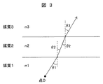
n1*sinθ1 = n2*sinθ2 ・・・(1)
n2*sinθ2 = n3*sinθ3 ・・・(2)
ここで、発光側が空気で、光学窓がガラス、光伝送光学系が空気である場合には、点Oから光学窓へ角θ1=30°で入射する光線を考えるとθ2、θ3は表1で示す角度となる。

102、202・・・光学窓
103、203・・・流路
104、204・・・測光部
105、205・・・供給口
106、206・・・排出口
107、207・・・ポンプ
108、208・・・容器
109、209・・・反応液
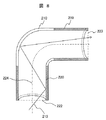
110、210・・・光伝送光学系
111、211・・・ホトマル
112、212・・蛍光体
113、213・・・光線
114、214・・・ヒーター
119、219・・・ミラー基材
120、220・・・反射面(内面)
122、222・・・入射口
123、223・・・出射口
124、224・・・光伝送光学系の中心軸
Claims (5)
- 発光物質を含む反応液を流す流路と、
流路温度を制御する温度制御部と、
前記反応液中に広がる発光物質からの光を通過させる光学窓と、
前記光学窓を通過した光を検知する光電子増倍管とを備え、
前記光電子増倍管からのデータを処理して前記反応液に含まれる発光物質の量を分析する自動分析装置において、
前記光学窓に対面する入射口と、
前記光電子増倍管の受光面と対面する出射口と、
一端に前記入射口を有し他端に前記出射口を有する中空部と、
前記入射口から入射した前記発光物質からの光を前記中空部の反射材により覆われた内面において反射させて前記出射口へ伝播する反射面とからなる光伝送光学系を設け、
前記光伝送光学系の入射口は、前記光学窓の上面に接触して配置され、
前記光電子増倍管の受光面の大きさは対面する前記出射口の大きさより大きくすることを特徴とする自動分析装置。 - 請求項1記載の自動分析装置において、
前記流路の一部が、前記流路に導入された反応液中に含まれる発光物質に発光を開始させるための測光部をなし、
前記光学窓は、前記測光部と前記光伝送光学系の間に設けられており、
前記光伝送光学系の入射口の大きさは、前記測光部よりも大きいことを特徴とする自動分析装置。 - 請求項1記載の自動分析装置において、
前記光伝送光学系の出射口は、前記光電子増倍管の受光面と離間して配置されていることを特徴とする自動分析装置。 - 請求項1記載の自動分析装置において、
前記光伝送光学系は、円筒形状をなす前記中空部と、その内面に形成された前記反射面とよりなり、
前記中空部と、前記入射口と、前記出射口とが、同一軸線上に配置されていることを特徴とする自動分析装置。 - 請求項1記載の自動分析装置において、
前記光伝送光学系は、円筒形状をなす前記中空部と、その内面に形成された前記反射面とよりなり、
前記中空部が曲線状をなして前記入射口と出射口の中心軸を異なる方向に向けて配置してなることを特徴とする自動分析装置。
Priority Applications (1)
| Application Number | Priority Date | Filing Date | Title |
|---|---|---|---|
| JP2014081060A JP5805259B2 (ja) | 2014-04-10 | 2014-04-10 | 自動分析装置 |
Applications Claiming Priority (1)
| Application Number | Priority Date | Filing Date | Title |
|---|---|---|---|
| JP2014081060A JP5805259B2 (ja) | 2014-04-10 | 2014-04-10 | 自動分析装置 |
Related Parent Applications (1)
| Application Number | Title | Priority Date | Filing Date |
|---|---|---|---|
| JP2010101799A Division JP5524698B2 (ja) | 2010-04-27 | 2010-04-27 | 自動分析装置 |
Publications (2)
| Publication Number | Publication Date |
|---|---|
| JP2014149305A true JP2014149305A (ja) | 2014-08-21 |
| JP5805259B2 JP5805259B2 (ja) | 2015-11-04 |
Family
ID=51572366
Family Applications (1)
| Application Number | Title | Priority Date | Filing Date |
|---|---|---|---|
| JP2014081060A Active JP5805259B2 (ja) | 2014-04-10 | 2014-04-10 | 自動分析装置 |
Country Status (1)
| Country | Link |
|---|---|
| JP (1) | JP5805259B2 (ja) |
Cited By (2)
| Publication number | Priority date | Publication date | Assignee | Title |
|---|---|---|---|---|
| JP2017138306A (ja) * | 2016-01-31 | 2017-08-10 | アークレイ株式会社 | 分析用具および分析装置 |
| WO2021205771A1 (ja) | 2020-04-08 | 2021-10-14 | 株式会社日立ハイテク | 自動分析装置 |
Citations (2)
| Publication number | Priority date | Publication date | Assignee | Title |
|---|---|---|---|---|
| JP2003083896A (ja) * | 2001-09-12 | 2003-03-19 | Kometto:Kk | 化学発光による分析方法および装置 |
| JP2004205415A (ja) * | 2002-12-26 | 2004-07-22 | Mitsubishi Electric Corp | 光分析測定用プローブ装置および溶液濃度モニタリング方法、ならびに分光分析装置 |
-
2014
- 2014-04-10 JP JP2014081060A patent/JP5805259B2/ja active Active
Patent Citations (2)
| Publication number | Priority date | Publication date | Assignee | Title |
|---|---|---|---|---|
| JP2003083896A (ja) * | 2001-09-12 | 2003-03-19 | Kometto:Kk | 化学発光による分析方法および装置 |
| JP2004205415A (ja) * | 2002-12-26 | 2004-07-22 | Mitsubishi Electric Corp | 光分析測定用プローブ装置および溶液濃度モニタリング方法、ならびに分光分析装置 |
Non-Patent Citations (2)
| Title |
|---|
| JPN6015003116; TERRY,J.M. 他: '"Chemiluminescence Detector with a Serpentine Flow Cell"' ANALYTICAL CHEMISTRY Volume 80, Number 24, 20081117, Pages 9817-9821 * |
| JPN6015003117; AMIRAV,A. 他: '"Pulsed Flame Photometer Detector for Gas Cheromatography"' ANALYTICAL CHEMISTRY Volume 67, Number 18, 19950915, Pages 3305-3318 * |
Cited By (3)
| Publication number | Priority date | Publication date | Assignee | Title |
|---|---|---|---|---|
| JP2017138306A (ja) * | 2016-01-31 | 2017-08-10 | アークレイ株式会社 | 分析用具および分析装置 |
| WO2021205771A1 (ja) | 2020-04-08 | 2021-10-14 | 株式会社日立ハイテク | 自動分析装置 |
| US12578351B2 (en) | 2020-04-08 | 2026-03-17 | Hitachi High-Tech Corporation | Automatic analyzer |
Also Published As
| Publication number | Publication date |
|---|---|
| JP5805259B2 (ja) | 2015-11-04 |
Similar Documents
| Publication | Publication Date | Title |
|---|---|---|
| CN102265140B (zh) | 光度计以及具备光度计的分析系统 | |
| US10126229B2 (en) | Optical measurement device | |
| JP6023805B2 (ja) | アンダーフィル光ファイバ試料インタフェースを有する光学分光計 | |
| JP5524698B2 (ja) | 自動分析装置 | |
| CN106198471B (zh) | 一种基于导光毛细管的生化荧光分析仪及其检测方法 | |
| CN104515743A (zh) | 一种基于导光金属毛细管的光度分析仪及其检测方法 | |
| KR101909380B1 (ko) | 형광 측정장치 및 그 형광 측정방법 | |
| JP2014032148A (ja) | 表面プラズモン励起増強蛍光取得構造体および表面プラズモン励起増強蛍光測定システム | |
| JP5805259B2 (ja) | 自動分析装置 | |
| EP3674734B1 (en) | Excitation light irradiation device and excitation light irradiation method | |
| EP3159677B1 (en) | Detection device | |
| EP3705875B1 (en) | An apparatus and method for detecting photoluminescent light emitted from a sample | |
| JPWO2018034208A1 (ja) | 測定方法 | |
| CN109001168A (zh) | 一种导光毛细管光度仪 | |
| JP5300249B2 (ja) | 液体分析装置 | |
| US10775307B2 (en) | Optical fiber fluorescence detection device | |
| JP6644329B2 (ja) | 導光路内蔵チップ、導光部材及び導光方法 | |
| CN108489903A (zh) | 一种导光毛细管光度仪 | |
| JP6529591B2 (ja) | 発光分析用検出装置および自動分析装置 | |
| CA3187130C (en) | Absorbance spectroscopy analyzer and method of use | |
| JP2015102455A (ja) | センサ装置および測定方法 | |
| CN211122535U (zh) | 荧光检测器 | |
| EP3273226A1 (en) | Detection device | |
| JP2006308412A (ja) | 蛍光共鳴検出装置 |
Legal Events
| Date | Code | Title | Description |
|---|---|---|---|
| A977 | Report on retrieval |
Free format text: JAPANESE INTERMEDIATE CODE: A971007 Effective date: 20150116 |
|
| A131 | Notification of reasons for refusal |
Free format text: JAPANESE INTERMEDIATE CODE: A131 Effective date: 20150203 |
|
| A521 | Written amendment |
Free format text: JAPANESE INTERMEDIATE CODE: A523 Effective date: 20150331 |
|
| TRDD | Decision of grant or rejection written | ||
| A01 | Written decision to grant a patent or to grant a registration (utility model) |
Free format text: JAPANESE INTERMEDIATE CODE: A01 Effective date: 20150818 |
|
| A61 | First payment of annual fees (during grant procedure) |
Free format text: JAPANESE INTERMEDIATE CODE: A61 Effective date: 20150901 |
|
| R150 | Certificate of patent or registration of utility model |
Ref document number: 5805259 Country of ref document: JP Free format text: JAPANESE INTERMEDIATE CODE: R150 |
|
| S531 | Written request for registration of change of domicile |
Free format text: JAPANESE INTERMEDIATE CODE: R313531 |
|
| S533 | Written request for registration of change of name |
Free format text: JAPANESE INTERMEDIATE CODE: R313533 |
|
| R350 | Written notification of registration of transfer |
Free format text: JAPANESE INTERMEDIATE CODE: R350 |