JP2014200941A - Plate making apparatus - Google Patents
Plate making apparatus Download PDFInfo
- Publication number
- JP2014200941A JP2014200941A JP2013076725A JP2013076725A JP2014200941A JP 2014200941 A JP2014200941 A JP 2014200941A JP 2013076725 A JP2013076725 A JP 2013076725A JP 2013076725 A JP2013076725 A JP 2013076725A JP 2014200941 A JP2014200941 A JP 2014200941A
- Authority
- JP
- Japan
- Prior art keywords
- plate making
- stencil sheet
- stencil
- making pressure
- plate
- Prior art date
- Legal status (The legal status is an assumption and is not a legal conclusion. Google has not performed a legal analysis and makes no representation as to the accuracy of the status listed.)
- Pending
Links
Images





Landscapes
- Manufacture Or Reproduction Of Printing Formes (AREA)
Abstract
【課題】孔版原紙の品質にかかわらずに孔版原紙に同等の良好な品質で穿孔を施すことを、装置寿命を短くすることなく行うことができる製版装置および孔版印刷装置を提供することを課題とする。【解決手段】製版書込部20は、発熱素子が配列されているサーマルヘッド21と、サーマルヘッド21との間で孔版原紙23をニップ可能なプラテンローラ24と、サーマルヘッド21とプラテンローラ24とをニップさせ、孔版原紙23に製版圧をかけて孔版原紙23に製版圧を付与する製版圧付与機構508と、製版圧付与機構508による製版圧を可変にする製版圧可変機構508とを備えている。【選択図】図4An object of the present invention is to provide a stencil printing apparatus and a stencil printing apparatus capable of perforating a stencil paper with the same good quality regardless of the quality of the stencil paper without shortening the life of the apparatus. To do. A plate-making writing unit includes a thermal head in which heating elements are arranged, a platen roller that can nip a stencil sheet between the thermal head, a thermal head, and a platen roller. A plate making pressure applying mechanism 508 for applying a plate making pressure to the stencil sheet 23 and applying a plate making pressure to the stencil sheet 23, and a plate making pressure variable mechanism 508 for changing the plate making pressure by the plate making pressure applying mechanism 508. Yes. [Selection] Figure 4
Description
本発明は、サーマルヘッドを用いて感熱孔版原紙に穿孔を形成して製版を行う製版装置に関する。 The present invention relates to a plate making apparatus for making a plate by forming perforations in a heat-sensitive stencil sheet using a thermal head.
従来より、孔版印刷に用いられる製版装置としては、多数の発熱素子が配列されてなるサーマルヘッドと感熱孔版原紙(以下単に孔版原紙ともいう)の熱可塑性樹脂フィルム(以下単にフィルムともいう)側とを圧接させた状態で、各発熱素子に画像情報に基づいて穿孔用電力を供給して該発熱素子を発熱駆動するとともに、発熱素子の配列方向を主走査方向とし主走査方向と直交する副走査方向にサーマルヘッドと孔版原紙(マスター)とを相対移動させて1枚分の画像情報を担持する穿孔を孔版原紙に形成するものが知られている。 Conventionally, as a plate making apparatus used for stencil printing, a thermal head in which a large number of heating elements are arrayed and a thermoplastic resin film (hereinafter also simply referred to as film) side of a heat sensitive stencil paper (hereinafter also simply referred to as stencil paper) In a state where the heating element is in pressure contact, the heating power is driven by supplying power for punching to each heating element based on image information, and the sub-scanning is orthogonal to the main scanning direction with the arrangement direction of the heating elements as the main scanning direction. There is known a technique in which a thermal head and a stencil sheet (master) are moved relative to each other in a direction to form perforations that carry image information for one sheet on the stencil sheet.
このような製版装置において1画素分を穿孔する際には、サーマルヘッドを構成する全発熱素子の平均抵抗値と目標パワーとから算出した一定の印加電圧を一定時間に亘って連続的に発熱素子に印加するのが一般的であり、その際、目標パワーとなるように電源供給回路から出力される印加電圧を設定しているのが一般的であった。 When punching one pixel in such a plate making apparatus, a constant applied voltage calculated from the average resistance value of all the heating elements constituting the thermal head and the target power is continuously applied over a certain period of time. In general, the applied voltage output from the power supply circuit is set so as to achieve the target power.
しかしながら、予め定めた目標パワーとなるように印加電圧を設定しても、穿孔される孔版原紙の表面に凹凸があるなど表面状態が悪化・変質していると穿孔径がバラ付いて穿孔性能が低下し、結果として印刷物に白点などの画像不良が発生する。 However, even if the applied voltage is set so as to achieve a predetermined target power, if the surface condition is deteriorated or deteriorated, such as the surface of the stencil sheet to be punched, the punching diameter will vary and the punching performance will be poor. As a result, image defects such as white spots occur in the printed matter.
また、孔版原紙はフィルムと支持体(主に和紙)を接着剤で張り付けて製造しているが、接着剤の塗布量が多すぎる場合や塗布量にバラ付きがある場合にも穿孔径がバラ付いて穿孔性能が低下する。 In addition, stencil paper is manufactured by pasting a film and a support (mainly Japanese paper) with an adhesive, but the perforation diameter varies even when the amount of adhesive applied is too large or when the amount applied varies. In addition, perforation performance is reduced.
つまり、予め定めた目標パワーとなるように印加電圧を設定しても、孔版原紙の表面の凹凸すなわち表面状態の品質(フィルム表面の平滑性)や接着剤の塗布量など、孔版原紙の品質を左右する要因に応じて穿孔径がバラ付いてしまうという問題がある。 In other words, even if the applied voltage is set so as to achieve a predetermined target power, the quality of the stencil sheet, such as the unevenness of the surface of the stencil sheet, that is, the quality of the surface state (smoothness of the film surface) and the amount of adhesive applied, can There is a problem in that the diameter of the perforations varies depending on the factors that influence it.
さらに、目標パワーが一定すなわち総発熱エネルギ量が一定の場合であっても、孔版原紙の品質状態それぞれにおいては穿孔径にバラ付きがないものの低品質時と高品質時とでは穿孔径に差が生じ、結果として、印字性能に差が生じるという場合もある。 Furthermore, even when the target power is constant, that is, when the total amount of heat generated is constant, there is no variation in the perforation diameter in each quality state of the stencil paper, but there is a difference in perforation diameter between low quality and high quality. As a result, a difference in printing performance may occur.
これらの対策として、特許文献1には、穿孔用電圧を変えることが提案されている(例えば特許文献1参照)。
As countermeasures against these problems,
しかし、孔版原紙の表面状態が悪化して表面の凹凸が大きくなって孔版原紙のフィルムとTPH(サーマルヘッド)の発熱体とが密着できなくなった場合、特許文献1のようにTPHの穿孔用電圧を変えるだけでは穿孔不発を防止することが難しい。従って、この場合には、孔版原紙に対してTPHと孔版原紙のフィルム(PETフィルム)とを密着させるために、TPHとプラテンローラとの間に挟まれる孔版原紙を介して、TPHをより強い力でプラテンローラに向けて押し付ける必要がある。このため、製版装置の圧力をかける機構への負荷が大きくなるので装置寿命が短くなるという弊害が生じる。
However, when the surface condition of the stencil sheet deteriorates and the surface irregularities become large and the film of the stencil sheet and the heating element of the TPH (thermal head) cannot be brought into close contact with each other, the voltage for punching the TPH as in
本発明は上記事情に鑑みてなされたものであり、孔版原紙の品質にかかわらずに孔版原紙に同等の良好な品質で穿孔を施すことを、装置寿命を短くすることなく行うことができる製版装置を提供することを課題とする。 The present invention has been made in view of the above circumstances, and a stencil making apparatus capable of perforating stencil paper with the same good quality regardless of the quality of the stencil paper without shortening the device life. It is an issue to provide.
上記目的を達成するために、本発明に係る製版装置の第1の特徴は、発熱素子が配列されているサーマルヘッドと、前記サーマルヘッドとの間で孔版原紙をニップ可能なプラテンローラと、前記サーマルヘッドと前記プラテンローラとをニップさせ、前記孔版原紙に製版圧を付与する製版圧付与手段と、前記製版圧付与手段による前記製版圧を可変する製版圧可変手段と、を備えたことにある。 In order to achieve the above object, the first feature of the plate making apparatus according to the present invention is that a thermal head in which heating elements are arranged, a platen roller capable of nipping a stencil sheet between the thermal head, And a plate making pressure applying means for applying a plate making pressure to the stencil sheet, and a plate making pressure changing means for changing the plate making pressure by the plate making pressure applying means. .
本発明に係る製版装置の第2の特徴は、前記製版圧可変手段による製版圧を制御する製版圧制御手段を備えたことにある。 The second feature of the plate making apparatus according to the present invention is that it comprises plate making pressure control means for controlling the plate making pressure by the plate making pressure variable means.
本発明に係る製版装置の第3の特徴は、前記孔版原紙の品質を検出する検出手段を備え、前記製版圧制御手段は、前記検出手段から受けた信号に基づいて製版圧を制御することにある。 A third feature of the plate making apparatus according to the present invention is that it comprises a detecting means for detecting the quality of the stencil sheet, and the plate making pressure control means controls the plate making pressure based on a signal received from the detecting means. is there.
本発明に係る製版装置の第1の特徴によれば、製版圧可変手段を設けており、孔版原紙の表面凹凸などの品質劣化が生じているときに製版圧を上げ、そうでないときには製版圧を通常どおりとすることが可能なので、孔版原紙の品質にかかわらずに孔版原紙に同等の良好な品質で穿孔を施すことを、装置寿命を短くすることなく行うことができる製版装置とすることができる。 According to the first feature of the plate-making apparatus according to the present invention, plate-making pressure variable means is provided, and the plate-making pressure is increased when quality deterioration such as surface irregularities of the stencil sheet is generated, and if not, the plate-making pressure is increased. Since it is possible to perform as usual, it is possible to provide a plate making apparatus capable of performing perforation with the same good quality on the stencil sheet regardless of the quality of the stencil sheet without shortening the life of the apparatus. .
本発明に係る製版装置の第2の特徴によれば、使用者が製版圧を手動で変更しなくても済む構成にすることができる。 According to the 2nd characteristic of the plate-making apparatus which concerns on this invention, it can be set as the structure which a user does not need to change plate-making pressure manually.
本発明に係る製版装置の第3の特徴によれば、検出された孔版原紙の品質に応じて製版圧を制御するので、孔版原紙の品質にかかわらずに孔版原紙に同等の良好な品質の穿孔を施すことを孔版原紙ごとに確実に行うことができる。 According to the third feature of the plate making apparatus according to the present invention, since the plate making pressure is controlled in accordance with the detected quality of the stencil sheet, perforation with a good quality equivalent to that of the stencil sheet is possible regardless of the quality of the stencil sheet. Can be reliably performed for each stencil sheet.
以下、添付図面を参照して、本発明の実施の形態について説明する。以下の説明では、すでに説明したものと同一または類似の構成要素には同一または類似の符号を付し、その詳細な説明を適宜省略している。 Embodiments of the present invention will be described below with reference to the accompanying drawings. In the following description, the same or similar components as those already described are denoted by the same or similar reference numerals, and detailed description thereof is omitted as appropriate.
また、図面は模式的なものであり、寸法比などは現実のものとは異なることに留意すべきである。従って、具体的な寸法比などは以下の説明を参酌して判断すべきものである。又、図面相互間においても互いの寸法の関係や比率が異なる部分が含まれていることはもちろんである。 In addition, it should be noted that the drawings are schematic and the dimensional ratios and the like are different from actual ones. Therefore, specific dimensional ratios and the like should be determined in consideration of the following description. Moreover, it is a matter of course that portions having different dimensional relationships and ratios are included between the drawings.
また、以下に示す実施の形態は、この発明の技術的思想を具体化するための例示であって、この発明の実施の形態は、構成部品の材質、形状、構造、配置等を下記のものに特定するものではない。この発明の実施の形態は、要旨を逸脱しない範囲内で種々変更して実施できる。また、以下の説明では、孔版原紙としてどのサイズの原紙であっても適用可能である。 The following embodiments are exemplifications for embodying the technical idea of the present invention, and the embodiments of the present invention are described below in terms of the material, shape, structure, arrangement, etc. of the components. It is not something specific. The embodiments of the present invention can be implemented with various modifications without departing from the scope of the invention. Further, in the following description, any size base paper can be applied as the stencil base paper.
(全体構成)
図1は本発明の一実施形態(以下、本実施形態という)の製版装置を適用した孔版印刷装置の構成を示す側断面図、図2はこの孔版印刷装置の上面に設けられた操作パネルの概要を示した平面図である。本実施形態の孔版印刷装置1は、製版用の出力ヘッドとしてサーマルヘッド21を使用しており、製版読取部10、製版書込部(製版装置)20、カッタ部30、および印刷部40から構成されている。
(overall structure)
FIG. 1 is a side sectional view showing a configuration of a stencil printing apparatus to which a plate making apparatus according to an embodiment of the present invention (hereinafter referred to as this embodiment) is applied, and FIG. 2 is an operation panel provided on the upper surface of the stencil printing apparatus. It is the top view which showed the outline | summary. The
製版読取部10は、被複写物である原稿13をセットする原稿セット台12と、原稿セット台12上にセットされた原稿13を検知する原稿センサ17と、原稿センサ17の検知信号を受けた読取モータ18により回転駆動される原稿搬送ローラ対14と、搬送されてきた原稿13の画像を光学的に読み取り電気信号に変換する密着型のラインイメージセンサ11と、該ラインイメージセンサ11で読み取られた原稿13を原稿排紙トレー19に排出するためのステッピングモータなどからなる読取モータ18により回転駆動される原稿排出ローラ対15とから構成されている。なお、原稿搬送ローラ対14の後流部には、搬送されてきた原稿13を検知することで後述する製版書込部20の処理のスタートを決定する原稿INセンサ16が設けられている。
The plate-making
製版書込部20は、それぞれが複数の発熱素子21Zを有する4つのヘッドブロック21a〜21dからなるサーマルヘッド21(図5参照)と、孔版原紙ロール22から送り出される孔版原紙(マスタ)23のフィルム面側をサーマルヘッド21に押し当てながら搬送するステッピングモータなどからなる書込モータ25により回転駆動されるプラテンローラ24と、サーマルヘッド21によって製版された孔版原紙23を後述するドラム(版胴)33のクランプ部32に向けて搬送する書込モータ25により回転駆動される原紙搬送ローラ対26とから構成されている。プラテンローラ24、書込モータ25、および原紙搬送ローラ対26により本実施形態の孔版印刷装置の副走査手段が構成される。
The
製版書込部20の孔版原紙ロール22とプラテンローラ24(サーマルヘッド21)との間には孔版原紙23のフィルム面側の表面状態を光学的に自動検知する原紙情報取得手段としてのマスタ表面センサ(光沢度計)300が設けられている。
A master surface sensor as a stencil sheet information acquisition means for optically automatically detecting the surface state of the
カッタ部30は、サーマルヘッド21によって製版された孔版原紙23がドラム33に巻装された所定量の長さになったときに、その孔版原紙23を切断するカッタ31を備えている。
The
印刷部40は、ドクタローラ46とスキージローラ47間に形成されたインキ溜り48により一定量のインキをその内面に供給するインキ供給部を内蔵するドラム33と、給紙台44上に積載された印刷用紙積層体から1枚づつ印刷用紙43をピックアップして搬送するピックアップローラ46と、ピックアップローラ46から搬送されてきた印刷用紙43を所定のタイミングで送り出すタイミングローラ42と、タイミングローラ42より搬送路41に送り出されてきた印刷用紙43をドラム33の外周面に押し付けるプレスローラ35と、印刷された印刷用紙43をドラム33より剥ぎ取るための分離爪39と、ドラム33より剥ぎ取られた印刷用紙43を排紙積載する排紙台49とから構成されている。
The
ドラム33の外周面にはサーマルヘッド21により製版され搬送されてきた孔版原紙23の先端部をクランプするクランプ部32が設けられている。クランプ終了後、製版済の孔版原紙23は、ドラム33がメインモータ34により回転されることによりその外周面に巻装される。
On the outer peripheral surface of the
なお、この孔版印刷装置の上面には、図2に示すように、LCDなどからなる表示パネル401と操作キー群402とを有する操作パネル400が設けられており、ユーザが表示パネル401の画面に表示される種々の情報を参照しながら操作キー群402のいずれかのキーを操作できるように構成されている。
On the upper surface of the stencil printing apparatus, as shown in FIG. 2, an
操作キー群402は、製版スタートキー、印刷スタートキー、印刷モード設定キー、印刷枚数を入力するためなどに用いられるテンキー402a、リセットキー、ジョブ緊急停止キーなど、通常の孔版印刷装置に設けられている操作キーを備えている。
The operation
(サーマルヘッドによる製版圧)
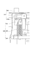
図3は、本実施形態の製版書込部20の製版圧可変機構を説明する側面図である。図4は、製版書込部20の製版圧可変機構に回動力を発生させる構成を説明する斜視図である。製版書込部20は、サーマルヘッド21とプラテンローラ24とをニップさせ、孔版原紙23に製版圧を付与する製版圧付与機構508と、製版圧付与機構508による製版圧を可変にする製版圧可変機構510と、を備えている。そして、製版書込部20は、後述の製版圧制御回路180によって、製版圧可変機構510による製版圧を制御して、孔版原紙23に形成する穿孔のサイズを調整することが可能になっている。
(Prepressing pressure with thermal head)
FIG. 3 is a side view illustrating the plate making pressure variable mechanism of the plate making /
本実施形態では、図3、図4に示すように、製版書込部20に組み込まれる筐体512と、筐体512に取り付けられたサーマルヘッド保持部514と、が設けられている。サーマルヘッド保持部514は、筐体512に設けられた回動軸518まわりに回動可能に軸止されており、回動軸518まわりに生じるサーマルヘッド保持部514の回動力によって、サーマルヘッド21がプラテンローラ24を押圧するようになっている。
In the present embodiment, as shown in FIGS. 3 and 4, a
そして、本実施形態では、筐体512に取り付けられた正逆両方向に回転可能なモータ520と、モータ520の回転軸520aにねじ係合している引っ掛け部材522と、引っ掛け部材522と筐体512のバネ係止部524(図4参照)とに掛け渡された引張コイルバネ526と、が設けられている。
In the present embodiment, a
この構成により、バネ係止部524に引張コイルバネ526の引張り力が作用することにより、サーマルヘッド保持部514に上記回動力が作用するようになっている。また、モータ520の回転軸520aの回転(正方向、逆方向)によって引っ掛け部材522が回転軸520aの軸方向に沿って進退動することで、引張コイルバネ526に生じる引張り力が調整されるようになっている。従って、本実施形態では、引っ掛け部材522、バネ係止部524、および、引張コイルバネ526が製版圧付与機構508を構成し、モータ520および回転軸520aが製版圧可変機構510を構成している。
With this configuration, when the tension force of the
(サーマルヘッドの発熱、および、穿孔)
図5はサーマルヘッド21の詳細を示す回路図、図6は上記構成による孔版印刷装置の製版書込部20の制御回路系を中心とした概要を示したブロック図である。
(Thermal head heat generation and perforation)
FIG. 5 is a circuit diagram showing details of the
サーマルヘッド21は、図5に示すように、4096個の発熱素子21Zを有しており、消費電力を抑えるために、1024個の発熱素子21Zごとに4つのブロック(21a〜21d)に分割されて、ヘッド制御回路100により各ブロックが時分割に発熱駆動されるようになっている(図5中1〜4096は画素に対応する発熱素子番号)。
As shown in FIG. 5, the
図6に示すように、サーマルヘッド21を用いて孔版原紙23に製版を行う制御回路系には、装置全体をコントロールするシステム制御マイコン410が設けられ、該マイコン410には、電源供給回路140、ヘッド制御信号生成回路160、印字データ生成回路170、および、製版圧制御回路180を有するヘッド制御回路100と、操作パネル400と、製版読取部10と、書込モータ25を回転駆動するモータコントローラ28と、マスタ表面センサ300とが接続されている。システム制御マイコン410からは電源供給回路140などを制御するための指令信号C1,…,C7が出力される。
As shown in FIG. 6, a
原稿13を原稿台12にセットし、その先端を原稿搬送ローラ対14に突き当てると、原稿センサ17が原稿13を検知し製版動作が可能であることが表示パネル401上に表示される。
When the
所定サイズの印刷用紙43が給紙台44にセットされている状態で製版スタートキーを押し下げると、図示しない被複写物サイズ検出手段によって印刷用紙43のサイズが検出されるとともに表示パネル401上にその情報が表示され、原稿搬送ローラ対14が読取モータ18の駆動により回転され原稿送り開始が行われる。続いて原稿INセンサ16が原稿13が搬送されてきたことを検知し、次いで所定長さ分だけ原稿13を送ると孔版原紙23がプラテンローラ24の駆動によって搬送され孔版原紙送り開始が行われる。
When the plate making start key is depressed while the
この原紙送り開始と同時に、製版読取部10のラインイメージセンサ11により原稿13によって所定サイズの原稿13の画像が光学的に読み取られる。この原稿13を読み取って得た多値データは図示しない画像処理回路に入力され2値データに変換された後ヘッド制御回路100の印字データ生成回路170に入力され、システム制御マイコン410の指令に基づいて、サーマルヘッド21の各ブロック21a〜21dに出力されるシリアル形式の印字データ DAT1〜4がサーマルヘッド21に向けて出力される。
Simultaneously with the start of feeding of the base paper, the image of the original 13 having a predetermined size is optically read by the original 13 by the
この画像読取りに並行して、ヘッド制御信号生成回路160においては、システム制御マイコン410の指令に基づいて、印字データ DAT1〜4を各発熱素子21Zに出力するためのクロック CLK1〜4、シリアル形式の印字データDAT1〜4 をパラレル信号に変換し保持するためのラッチ信号/LAT1〜4、サーマルヘッド21の各ブロックの各発熱素子21Zに印加される発熱信号(イネーブル信号、ストローブ信号/STB)/ENL1〜4を作成し、サーマルヘッド21にこれら各種制御信号を出力する。
In parallel with this image reading, in the head control
サーマルヘッド21には、図5に示すように出力回路72が設けられている。出力回路72は、ヘッド制御回路100から入力された印字データDAT1〜4 、ラッチ信号/LAT 1〜4 、イネーブル信号/ENL1〜4、クロックCLK1〜4 という4つの信号を使用して、サーマルヘッド21の分割された各ブロックそれぞれの発熱素子21Zを時分割に発熱駆動する。
The
すなわち、サーマルヘッド21に入力されたシリアル形式の印字データDAT1〜4 は1024ビットのシリアル入力シフトレジスタ75によりパラレルデータに変換され、所定のタイミングで発せられるラッチ信号/LAT1〜4によりラッチ76に保持される。各発熱素子21Zの一端には電源供給回路140から供給される所定の印加電圧Vhが印加され、入力されたイネーブル信号/ENL1〜4とラッチ76に保持されたデータとの論理積の結果が発熱素子21Zの他端に入力されることによって所望のタイミングで発熱素子21Zが発熱駆動される。
That is, serial-format print data DAT1 to 4 input to the
以上のようにして、原稿13を読み取って得たデータに基づいて、孔版原紙23への穿孔画像の形成すなわち製版が行われ、その後所定のプラテン送り量分が送られると孔版原紙送り停止が行われ、その後に原稿13が排出されると原稿送り停止が行われ、また製版済みの孔版原紙23は原稿搬送ローラ対26によって一定量搬送され、その一端部がクランプ部32において固定された後、孔版原紙23はドラム33が回転されることによってドラム33外周面に巻装され所定量巻装された後カッタ31で切断される。これによりドラム33の外周面には孔版原紙23が完全に巻装された状態となり、印刷動作待機状態となる。
As described above, based on the data obtained by reading the original 13, the formation of a punched image on the
次にテンキー402aにより印刷枚数を入力すると表示パネル401上にそのデータが表示される。この状態で印刷スタートキーが押下げられると印刷用紙43はピックアップローラ46により1枚づつタイミングローラ42へ搬送され、一次待機した後にドラム33の回転のある所定のタイミングでタイミングローラ42が駆動されて搬送路41に送り込まれる。搬送路41に送り込まれた印刷用紙43は、プレスローラ35によりドラム33の外周面に押し当てられ孔版原紙23に形成された穿孔画像を通過したインキが転写されて印刷が行われる。印刷が行われた印刷用紙43は、分離爪39によってドラム33の外周面から剥ぎ取られ矢印Z方向に搬送されて排紙台49へ排出される。
Next, when the number of prints is input using the
上記孔版印刷装置においては、品質の異なる(価格の異なる)幾つかの種類の孔版原紙を装着することができるようになっている。ここで、穿孔径のバラ付き原因の1つである原紙表面の凹凸具合(フィルム表面の平滑性)を悪化させる要因を調べたところ以下のことが判った。 In the stencil printing apparatus, several types of stencil sheets having different quality (different prices) can be mounted. Here, when the factor which worsens the unevenness | corrugation degree (smoothness of a film surface) of the base paper surface which is one of the causes of the variation in a punching diameter, the following things were found.
第1に、孔版原紙はフィルムと和紙などの支持体とを接着剤で張り合わせて製造するが、皺が発生しないようお互い一定の張力をかけて張り合わせる。このとき、双方の弾性率が同じであれば表面の平滑性が高い(良好な)原紙をつくることができるが、逆に弾性率が異なれば表面の平滑性が低くなる。 First, a stencil sheet is manufactured by laminating a film and a support such as Japanese paper with an adhesive, but they are laminated together with a certain tension so as not to cause wrinkles. At this time, if both the elastic moduli are the same, a base paper having a high (smooth) surface smoothness can be produced. Conversely, if the elastic moduli are different, the surface smoothness is low.
第2に、張り合わせて原紙を巻き取ってロール状にするが、ロール状に巻き取られることでフィルム面の上に和紙がある圧力で重なる。これによって和紙の凹凸がフィルム面に反映され、フィルム面の表面の平滑性が全体的に低くなる。またこのときの平滑性の程度は和紙の密度や素材などによっても異なる。 Secondly, the base paper is laminated and wound up into a roll shape, and the roll is wound into a roll shape so that it overlaps with the pressure of Japanese paper on the film surface. As a result, the irregularities of the Japanese paper are reflected on the film surface, and the smoothness of the surface of the film surface is lowered overall. The degree of smoothness at this time also varies depending on the density and material of the Japanese paper.
例えば、フィルムは1種類で和紙は数種類のものを使用するものとすれば、和紙の弾性率、密度、素材の差に応じて表面状態の良い(平滑性の良好な)原紙や悪い原紙が出来上がる。現実的には弾性率、密度、素材の3つの要素が全て良い和紙または悪い和紙というのものはないが、トータル的に光沢度(反射率)が高いすなわち平滑性の良好な原紙は高品質で値段が高く、光沢度の低いものは低品質で値段が安いと言える。 For example, if one kind of film and several kinds of Japanese paper are used, a base paper having a good surface condition (good smoothness) or a bad base paper is produced according to the elastic modulus, density, and material difference of the Japanese paper. . In reality, none of the three elements of elastic modulus, density, and material is good or bad Japanese paper, but the base paper with high gloss (reflectance), that is, good smoothness is of high quality. High price and low gloss are low quality and low price.
一方、孔版原紙の表面の平滑性が低下すると、サーマルヘッドに孔版原紙を通常の圧力で押し当てても、ミクロ的にみるとサーマルヘッドの1発熱素子(抵抗体)と原紙のフイルム面との密着性が悪い部分がでてくるため、この部分では発熱素子の発熱エネルギが原紙のフィルム面に届き難くなり穿孔品質が低下することになる。 On the other hand, when the smoothness of the surface of the stencil sheet is lowered, even if the stencil sheet is pressed against the thermal head at normal pressure, there is a microscopic relationship between one heating element (resistor) of the thermal head and the film surface of the stencil sheet. Since a part with poor adhesion comes out, the heat generation energy of the heating element does not easily reach the film surface of the base paper in this part and the perforation quality is lowered.
そこで本実施形態においては、図7に示すようなフローチャートに基づいて孔版原紙23の製版圧を調整するとよい。すなわち、先ずマスタ表面センサ300により孔版原紙23の光沢度(反射率)を検出する(S1)。なお、この光沢度は孔版原紙23の表面の凹凸に対応する。
Therefore, in the present embodiment, the plate making pressure of the
この検出により得た受光素子302の信号値S1(A/D変換後のデータでもよい)に基づいて、当該孔版原紙23への適切な製版圧を決定する(S2)。例えば、図8に示すように、孔版原紙23の光沢度が低いほど、サーマルヘッド21による製版圧(ニップ圧)を上昇させる。また、製版圧の決定では、例えば、信号値S1と適切な製版圧との対応表をシステム制御マイコン410が予め有していて、この対応表に基づいて決定してもよい。
Based on the signal value S1 of the
そして、モータ520を作動させてサーマルヘッド保持部514に回動軸518まわりの所定の回動力を付与することで、決定した製版圧で孔版原紙23が押圧されるように、システム制御マイコン410がモータ520の回転数あるいは回転角度を設定する。この結果、サーマルヘッド21がプラテンローラ24に向けて押圧され、上記の決定した製版圧となる(S3)。そして、この製版圧で孔版原紙23を製版し、その後に印刷を行う(S4)。
Then, the
さらに次の原稿13があるときにはステップ11(S1)に戻り上記同様の処理を施す一方(S5−YES)、次の原稿13がなければ処理を終了させる(S5−NO)。 If there is a next original 13, the process returns to step 11 (S1) to perform the same processing as above (S5-YES). If there is no next original 13, the process is terminated (S5-NO).
このように、上記構成の装置によれば、孔版原紙23の表面状態をマスタ表面センサ300により自動検知して製版圧を自動設定すれば、孔版原紙23の表面状態に関わらずある程度の穿孔品質を維持することを、確実に行うことができる。この結果、例えば、製版圧を高くすることで表面凹凸の激しい劣化した孔版原紙23に対しても発熱エネルギを十分に伝達することができるので、高品質の孔版原紙を用いた場合と同様の穿孔サイズで白点などの画像不良を極力減らすことのできる製版を行うことができる。
As described above, according to the apparatus having the above configuration, if the surface state of the
また、製版圧制御回路180(製版圧制御手段)を設けているので、使用者が製版圧を手動で変更しなくても済む構成にすることができる。 Further, since the plate-making pressure control circuit 180 (plate-making pressure control means) is provided, a configuration in which the user does not have to manually change the plate-making pressure can be achieved.
また、上記実施形態では、孔版原紙23の表面状態をマスタ表面センサ300により自動検知して製版圧を自動設定するようにしていたが、ユーザによるマニュアル設定を行うこともできる。例えば自動検知用のセンサが設けられていない場合には、ユーザが孔版原紙23の表面状態を判断して製版圧を設定するようにしてもよい。なお、孔版原紙23の表面劣化は印刷画像の画質低下に直接影響するので、ユーザがマニュアル設定を行う場合には、試し刷りなどを行った印刷結果から間接的に孔版原紙23の表面状態の品質を判断することにより、孔版原紙23の品質に関する情報を取得してもよい。
In the above embodiment, the surface state of the
また、マスタ表面センサ300によって検出された孔版原紙23の品質に応じて製版圧を制御するので、孔版原紙23の品質にかかわらずに孔版原紙23に同等の良好な品質の穿孔を施すことを各孔版原紙ごとに確実に行うことができる。
Further, since the stencil pressure is controlled in accordance with the quality of the
また、ロール状に巻き上げられた孔版原紙は、巻きはじめのときには強くテンションをかけないとうまく巻き取れないため、該原紙の巻き芯付近になればなるほど巻き圧力が高くなり、原紙の巻き芯付近ほど表面の平滑性が悪くなってくる。つまり、原紙の種類が異なるだけでなく、原紙1本分の中でも平滑性は変化する、換言すれば、ロール状に巻き上げられた孔版原紙は、経時的に表面の平滑性が劣化することになる。この場合、原稿13が供給される都度孔版原紙23の表面状態をマスタ表面センサ300により検出するようにすれば、原紙1本分における表面品質の経時変化に対応することもできる。
In addition, the stencil sheet wound up in a roll shape cannot be wound well unless a strong tension is applied at the beginning of winding. The smoothness of the surface becomes worse. That is, not only the type of the base paper is different, but also the smoothness changes within one base paper, in other words, the surface smoothness of the stencil paper wound up in a roll shape deteriorates with time. . In this case, if the surface state of the
この場合、穿孔の各主走査ごとに表面状態を検出するようにすれば、原稿1枚分の穿孔過程における孔版原紙の平滑性の変化にも対応することができる。 In this case, if the surface state is detected for each main scanning of punching, it is possible to cope with a change in the smoothness of the stencil sheet during the punching process for one original.
また、マスタ表面センサ300で孔版原紙の表面の凹凸の程度(孔版原紙の品質)を検出するのは、孔版原紙1ロールごと、原稿1枚ごと、あるいは穿孔の1主走査ごとのいずれのタイミングに行ってもよい。この検出の機会が多いほど穿孔品質や印字品質をきめ細やかに調整できるのはいうまでもない。
The
さらに上記実施形態では、孔版原紙23の表面の平滑度に対応するマスタ表面センサ300により検知した孔版原紙23の光沢度(反射率)を表す受光素子302の信号値S1に基づいて孔版原紙23の適切な製版圧を決定しているが、これに限らず、信号値S1を基準値と比較して、反射率が高い場合は孔版原紙23の表面状態が高品質であり、反射率が低い場合は低品質であると判断し、その結果に応じて製版圧を切り替える2段階の調整としてもよい。これにより、製版圧の制御をより簡単にすることができる。
Further, in the above embodiment, the
また、孔版原紙23の種類毎に応じて製版圧がシステム制御マイコン410に予め設定されている構成にしてもよい。これにより、製版圧制御回路180による制御を簡単にすることができる。また、マスタ表面センサ300を用いて表面の凹凸を計測しなくても済む構成にすることが可能となる。
Further, the plate making pressure may be set in advance in the
また、孔版原紙23の製造年月日に応じて製版圧がシステム制御マイコン410に予め設定されている構成にしてもよい。これにより、同様に、製版圧制御回路180による制御を簡単にすることができる。また、マスタ表面センサ300を用いて表面の凹凸を計測しなくても済む構成にすることが可能となる。
Further, the stencil pressure may be set in the
また、孔版原紙23の平滑度に応じて製版圧がシステム制御マイコン410に予め設定されている構成にしてもよい。これにより、同様に、製版圧制御回路180による制御を簡単にすることができる。また、マスタ表面センサ300を用いて表面の凹凸を計測しなくても済む構成にすることが可能となる。
Further, the plate making pressure may be set in advance in the
また、上記実施形態では、孔版原紙の品質の一態様としてのフィルム表面の平滑度、換言すれば凹凸を問題としていたが、穿孔径のバラ付き発生原因となる孔版原紙の品質を左右する要因は必ずしもフィルム表面の平滑度に限らない。例えば、上述のように、孔版原紙の製造工程ではフィルムと支持体とを接着剤で張り合わせるが、接着剤の塗布量に応じて穿孔径にバラ付きが発生することもある。接着剤の塗布量の変化には、和紙の密度(種類)によるものと製造工程で発生するものとがある。塗布量は少なければ少ないほど穿孔品質には有利つまり穿孔径のバラ付きが少なくなり、塗布量が多ければ孔が開き難くなって穿孔径のバラ付きが多くなる。また塗布量自体にバラ付きがあれば、当然それで穿孔径のバラ付きが発生する。一方、孔版原紙の品質の一態様である接着剤の塗布量の増減に応じて孔版原紙の光透過率が変化する。したがって、この光透過率をフォトセンサなどの光学的な検出手段を用いて検出して、この検出結果に応じて上述同様の制御を行うことで、穿孔品質を均質化することもできる。 Further, in the above embodiment, the smoothness of the film surface as one aspect of the quality of the stencil sheet, in other words, unevenness has been a problem, but the factors that influence the quality of the stencil sheet that cause the variation in perforation diameter are It is not necessarily limited to the smoothness of the film surface. For example, as described above, in the stencil sheet manufacturing process, the film and the support are bonded together with an adhesive, but the perforation diameter may vary depending on the amount of adhesive applied. There are two types of changes in the amount of adhesive applied, one depending on the density (type) of Japanese paper and the other in the manufacturing process. The smaller the coating amount, the better the perforation quality, that is, the variation in the perforation diameter decreases. The larger the application amount, the more difficult the hole is opened, and the variation in the perforation diameter increases. Further, if the coating amount itself varies, naturally, the perforation diameter varies. On the other hand, the light transmittance of the stencil sheet changes according to an increase or decrease in the amount of adhesive applied, which is an aspect of the quality of the stencil sheet. Therefore, by detecting this light transmittance using an optical detection means such as a photosensor and performing the same control as described above according to the detection result, the perforation quality can be homogenized.
言い換えると、上記実施形態では、マスタ表面センサ300で孔版原紙23の表面の凹凸を検出し、この凹凸に応じて製版圧を制御する例で説明したが、凹凸に限らず、孔版原紙23にサーマルヘッド21で穿孔を形成して製版するに際して穿孔径に影響を与える孔版原紙特性(品質)に応じて製版圧を制御することで、孔版原紙の品質にかかわらずに孔版原紙に同等の良好な品質の穿孔を施すことを、装置寿命を短くすることなく行うことが可能である。
In other words, in the above-described embodiment, the
<検討例>
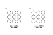
上記構成の孔版印刷装置1で、通常の孔版原紙(高品質原紙)、および、表面の凹凸の度合いが大きい孔版原紙(低品質原紙)に製版した例(実施例)を、それぞれ、図9(a)および(b)に示す。また、比較のために、従来の孔版印刷装置で、通常の孔版原紙(高品質原紙)、および、表面の凹凸の度合いが大きい孔版原紙(低品質原紙)に製版した例(従来例)を、それぞれ、図10(a)および(b)に示す。
<Examination example>
An example (Example) in which the
実施例では、通常の孔版原紙(高品質原紙)であっても、表面の凹凸の度合いが大きい劣化した孔版原紙(低品質原紙)であっても、穿孔径にばらつきがない。 In the examples, there is no variation in the perforation diameters, whether it is a normal stencil paper (high quality base paper) or a deteriorated stencil paper (low quality base paper) with a large degree of surface irregularities.
一方、従来例では、通常の孔版原紙(高品質原紙)に穿孔したときにはほぼ均一の穿孔径が形成されるが、同一製版条件のままで、表面の凹凸の度合いが大きい劣化した孔版原紙(低品質原紙)に穿孔したときには、図10(b)に示すように、穿孔径がばらつく。 On the other hand, in the conventional example, when a regular stencil sheet (high-quality stencil sheet) is perforated, a substantially uniform perforation diameter is formed. When the quality base paper is perforated, the perforation diameter varies as shown in FIG.
1 孔版印刷装置
20 製版書込部(製版装置)
21 サーマルヘッド
21Z 発熱素子
23 孔版原紙
24 プラテンローラ
180 製版圧制御回路(製版圧制御手段)
300 マスタ表面センサ(検出手段)
508 製版圧付与機構(製版圧付与手段)
510 製版圧可変機構(製版圧可変手段)
1
21 Thermal Head
300 Master surface sensor (detection means)
508 Plate making pressure applying mechanism (plate making pressure applying means)
510 Plate making pressure variable mechanism (plate making pressure variable means)
Claims (3)
前記サーマルヘッドとの間で孔版原紙をニップ可能なプラテンローラと、
前記サーマルヘッドと前記プラテンローラとをニップさせ、前記孔版原紙に製版圧を付与する製版圧付与手段と、
前記製版圧付与手段による前記製版圧を可変にする製版圧可変手段と、
を備えたことを特徴とする製版装置。 A thermal head in which heating elements are arranged;
A platen roller capable of nipping a stencil sheet with the thermal head;
A plate-making pressure applying unit that nips the thermal head and the platen roller and applies plate-making pressure to the stencil sheet;
Plate making pressure variable means for making the plate making pressure variable by the plate making pressure applying means;
A plate making apparatus characterized by comprising:
前記製版圧制御手段は、前記検出手段から受けた信号に基づいて前記製版圧を制御することを特徴とする請求項2記載の製版装置。 A detection means for detecting the quality of the stencil sheet,
3. The plate making apparatus according to claim 2, wherein the plate making pressure control means controls the plate making pressure based on a signal received from the detection means.
Priority Applications (1)
| Application Number | Priority Date | Filing Date | Title |
|---|---|---|---|
| JP2013076725A JP2014200941A (en) | 2013-04-02 | 2013-04-02 | Plate making apparatus |
Applications Claiming Priority (1)
| Application Number | Priority Date | Filing Date | Title |
|---|---|---|---|
| JP2013076725A JP2014200941A (en) | 2013-04-02 | 2013-04-02 | Plate making apparatus |
Publications (1)
| Publication Number | Publication Date |
|---|---|
| JP2014200941A true JP2014200941A (en) | 2014-10-27 |
Family
ID=52351837
Family Applications (1)
| Application Number | Title | Priority Date | Filing Date |
|---|---|---|---|
| JP2013076725A Pending JP2014200941A (en) | 2013-04-02 | 2013-04-02 | Plate making apparatus |
Country Status (1)
| Country | Link |
|---|---|
| JP (1) | JP2014200941A (en) |
-
2013
- 2013-04-02 JP JP2013076725A patent/JP2014200941A/en active Pending
Similar Documents
| Publication | Publication Date | Title |
|---|---|---|
| US20070285697A1 (en) | Printer | |
| US7878117B2 (en) | Stencil printing apparatus having controlled thermal head for perforating stencil | |
| JP4410500B2 (en) | Duplex printing device | |
| JP3958535B2 (en) | Plate making method and apparatus | |
| JP2014200941A (en) | Plate making apparatus | |
| JP2001328332A (en) | Printing equipment | |
| JP2002144689A (en) | Stencil printing machine | |
| JPH0867061A (en) | Thermosensitive stencil printing device | |
| JP4231537B2 (en) | Plate feeder | |
| JP4430345B2 (en) | Plate making apparatus and plate making printing apparatus | |
| JPH07241974A (en) | Thermal screen printing machine | |
| JP5005974B2 (en) | Duplex printing device | |
| JP5015577B2 (en) | Stencil printing machine | |
| JP2007168395A (en) | Printing device | |
| JP5304067B2 (en) | Thermal stencil printing machine | |
| JP2002144688A (en) | Stencil printer | |
| JP5034048B2 (en) | Stencil printing machine | |
| JP4712963B2 (en) | Plate making apparatus and plate making printing apparatus | |
| JP5181166B2 (en) | Thermal stencil printing machine | |
| JP2002001896A (en) | Plate making apparatus and plate making and printing apparatus | |
| JP4727213B2 (en) | Thermal stencil printing machine | |
| WO2022049749A1 (en) | Thermal printer | |
| JP5119439B2 (en) | Stencil printing machine | |
| JP2002052751A (en) | Color printing method and color printing apparatus | |
| JP2008307829A (en) | Stencil printing device |