JP2014201211A - Movable carriage and transport device - Google Patents
Movable carriage and transport device Download PDFInfo
- Publication number
- JP2014201211A JP2014201211A JP2013079185A JP2013079185A JP2014201211A JP 2014201211 A JP2014201211 A JP 2014201211A JP 2013079185 A JP2013079185 A JP 2013079185A JP 2013079185 A JP2013079185 A JP 2013079185A JP 2014201211 A JP2014201211 A JP 2014201211A
- Authority
- JP
- Japan
- Prior art keywords
- ground
- carriage
- wheel
- load
- movable carriage
- Prior art date
- Legal status (The legal status is an assumption and is not a legal conclusion. Google has not performed a legal analysis and makes no representation as to the accuracy of the status listed.)
- Pending
Links
Images


Landscapes
- Handcart (AREA)
Abstract
Description
本発明は、荷物を移動させるために使用する移動台車及び搬送装置に関し、特に、重量物の搬送・据付の際に用いられて好適な移動台車及び搬送装置に関するものである。 The present invention relates to a moving carriage and a transfer device used for moving a load, and more particularly to a moving carriage and a transfer device suitable for use in transferring and installing a heavy object.
従来の移動台車として、荷物を載せる台車本体に、水平方向に所定の軸間距離を隔てて所要のローラを配設したものが提案されている(例えば、特許文献1参照)。
なお、特許文献1には、この移動台車を荷物の四隅に敷いて荷物を4台の移動台車を用いて移動させる方法が記載されている。
As a conventional movable carriage, a carriage body on which a load is placed has been proposed in which a predetermined roller is disposed at a predetermined distance in the horizontal direction (see, for example, Patent Document 1).
しかしながら、上記の移動台車では、地面に若干の凹凸や段差があるだけでローラの回転が阻まれたり、地面に対するローラの接地圧が大きいことから地面が軟らかい場合、ローラが地面にめり込んだりするため、このような悪条件の地面での荷物の移動動作が困難であるという問題があった。 However, in the above moving carriage, the rotation of the roller is prevented only by a slight unevenness or a step on the ground, or when the ground is soft because the ground contact pressure of the roller against the ground is large, the roller sinks into the ground. There is a problem that it is difficult to move the luggage on the ground under such bad conditions.
本発明は、上記従来技術の有する問題点に鑑み、地面に若干の凹凸や段差があったり、地面が軟らかかったりするなどの悪条件の地面でも荷物の移動動作をスムーズに行うことができる移動台車及び搬送装置を提供することを目的とする。 In view of the above-described problems of the prior art, the present invention provides a movement that can smoothly move a load even on an unfavorable ground such as a slight unevenness or a step on the ground or a soft ground. It aims at providing a trolley | bogie and a conveying apparatus.
上記目的を達成するため、第1発明の移動台車は、荷物の下に敷いてその荷物を移動させる移動台車であって、荷物を載せる台車本体に、水平方向に所定の軸間距離を隔てて第1の車輪及び第2の車輪をそれぞれ配設し、複数のリンクを環状に連結してなるチェーンをそれら車輪に巻き掛け装着するとともに、地面と接する板面を有する履板を各リンクの接地面側に取り付けたことを特徴とする。 In order to achieve the above object, a mobile carriage according to a first aspect of the present invention is a mobile carriage that is laid under a load and moves the load, and is separated from the main body of the load by a predetermined axial distance in the horizontal direction. A first wheel and a second wheel are respectively arranged, and a chain formed by connecting a plurality of links in an annular shape is wound around these wheels and attached, and a shoe plate having a plate surface in contact with the ground is attached to each link. It is attached to the ground side.
この場合において、第1の車輪と第2の車輪との間におけるチェーンの下側部分の非接地面側に係合する係合部を有するチェーンガイドを設け、このチェーンガイドの係合部を、下に凸の膨らみを持たせた形状とするのが好ましい(第2発明)。 In this case, a chain guide having an engagement portion that engages with the non-grounding surface side of the lower portion of the chain between the first wheel and the second wheel is provided, and the engagement portion of the chain guide is It is preferable to have a shape having a convex bulge downward (second invention).
次に、第3発明の搬送装置は、第1発明又は第2発明に係る移動台車に、第1の車輪又は第2の車輪を回転駆動する回転駆動装置を設けて搬送台車を構成し、この搬送台車を、荷物の左側部分及び右側部分にそれぞれ対応させて少なくとも1台ずつ配設してなることを特徴とする。 Next, a transport device according to a third aspect of the present invention provides a transport cart by providing a rotary drive device that rotationally drives the first wheel or the second wheel in the mobile cart according to the first or second invention. It is characterized in that at least one transport cart is provided corresponding to each of the left side portion and the right side portion of the luggage.
第1発明の移動台車によれば、若干の凹凸や段差がある地面上を走行する際、履板とチェーンとからなる履帯によって形成される無限軌道が地面の凹凸や段差の上に敷設されるので、各車輪の回転運動がその無限軌道上で行われることになり、各車輪の回転が地面の凹凸や段差で阻害されることがなく、荷物の移動動作をスムーズに行うことができる。
また、荷物の荷重が第1の車輪と第2の車輪との間における履板を介して地面に伝えられるので、地面に対する接地圧を低めることができ、地面が軟らかい場合でも、履帯が地面にめり込むのを防ぐことができ、荷物の移動動作をスムーズに行うことができる。
According to the mobile carriage of the first invention, when traveling on the ground with slight irregularities and steps, an endless track formed by a crawler belt composed of a crawler plate and a chain is laid on the irregularities and steps on the ground. Therefore, the rotational movement of each wheel is performed on the endless track, and the rotation of each wheel is not hindered by the unevenness or level difference of the ground, and the movement operation of the load can be performed smoothly.
In addition, since the load of the load is transmitted to the ground via the crawler plate between the first wheel and the second wheel, the ground pressure against the ground can be reduced, and even if the ground is soft, the crawler belt is on the ground. It is possible to prevent intrusion and to smoothly move the luggage.
第2発明の移動台車によれば、チェーンガイドの係合部の膨らみによって履帯が第1の車輪と第2の車輪との間で下方に膨出されるので、地面に対し履帯が線状に接地されることになり、移動台車の操舵や旋回の各動作を容易に行うことができる。 According to the movable carriage of the second invention, the crawler belt bulges downward between the first wheel and the second wheel due to the swelling of the engaging portion of the chain guide, so that the crawler belt is linearly grounded with respect to the ground. Thus, each operation of steering and turning of the movable carriage can be easily performed.
第3発明の搬送装置においては、移動台車に車輪の回転駆動装置を設けて構成される搬送台車が荷物の左側部分及び右側部分にそれぞれ対応させて少なくとも1台ずつ配設され、これら左右の搬送台車のそれぞれの履帯の周速度の制御により、直進、操舵及び旋回の各動作が行われる。
すなわち、左右の搬送台車における履帯の周速度を同じとすることにより、搬送装置の直進動作が行われる。また、左右の搬送台車における履帯の周速度に差を持たせることにより、その差分に応じて、搬送装置の操舵動作が行われる。また、左右の搬送台車における履帯を互いに逆方向に周回運動させることにより、搬送装置の旋回動作が行われる。
第3発明の搬送装置によれば、第1発明又は第2発明に係る移動台車をベースとして自走可能に構成される搬送台車を組み合わせて構成されるので、地面に若干の凹凸や段差があったり、地面が軟らかかったりするなどの悪条件の地面で上記の直進、操舵及び旋回の各動作が行われても、各車輪の回転が地面の凹凸や段差で阻害されることがなく、また履帯が地面にめり込むことがなく、荷物の搬送動作をスムーズに行うことができる。
In the transfer device according to the third aspect of the present invention, at least one transfer trolley configured by providing a rotational drive device for the wheel on the movable trolley is disposed corresponding to each of the left side portion and the right side portion of the load. By controlling the peripheral speed of each crawler track of the carriage, each of straight movement, steering and turning operations is performed.
That is, by making the circumferential speeds of the crawler belts in the left and right transport carts the same, the transport device moves straight. Further, by providing a difference in the circumferential speed of the crawler belts between the left and right transport carts, the steering operation of the transport device is performed according to the difference. Further, the crawlers in the left and right transport carts are rotated in opposite directions to rotate the transport device.
According to the transport apparatus of the third invention, since the transport cart configured to be self-propelled based on the mobile cart according to the first or second invention is combined, there are some unevenness and steps on the ground. Even if the above-mentioned straight-ahead, steering, and turning operations are performed on the ground under adverse conditions such as the ground is soft, the rotation of each wheel is not hindered by unevenness or steps on the ground, and The crawler belt does not sink into the ground, and the cargo can be transported smoothly.
次に、本発明の移動台車及び搬送装置の実施の形態を、図面に基づいて説明する。 Next, embodiments of the movable carriage and the transfer device of the present invention will be described with reference to the drawings.
<搬送装置の概略説明>
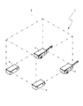
図1に示される搬送装置1は、荷物2の前側左右両角部にそれぞれ敷かれる搬送台車3、3と、荷物2の後側左右両角部にそれぞれ敷かれる移動台車4、4とを備えて構成されている。
<Overview of the conveying device>
A
<移動台車の説明>
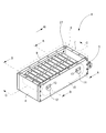
図2に示されるように、移動台車4は、台車本体5を備えている。
台車本体5は、荷物2を載せるための載置面を有する上板6を備え、この上板6の前端部、後端部、左側部及び右側部にそれぞれ対応するように前側板7、後側板8、左側板9及び右側板10がその上板6の下側に位置するように配設され、上板6と各側板7〜10とが所要のボルト(図示省略)で締結されるとともに、互いに隣接する側板同士7、9;7、10;8、9;8、10も所要のボルト(図示省略)で締結されることにより、強固な箱型構造体とされている。
なお、図示による説明は省略するが、荷物2とその荷物2を載せた移動台車4とを締結して移動台車4から荷物2がずれ落ちるのを防ぐために、上板6に固着したナットとそのナットに螺合するボルトとからなる締結固定具を備え付けるのが好ましい(搬送台車3についても同様)。
<Description of moving cart>
As shown in FIG. 2, the
The
In addition, although illustration description is abbreviate | omitted, in order to fasten the
前側板7と後側板8との間には、水平方向に所定の軸間距離を隔てて前軸11及び後軸12がそれぞれ配設されている。
前軸11の両端部は、例えば、キープレート等の軸固定手段13により左側板9及び右側板10にそれぞれ回転不能に支持されるとともに、後軸12の両端部も同様に、軸固定手段13により左側板9及び右側板10にそれぞれ回転不能に支持されている。
A
Both ends of the
<スプロケットの説明>
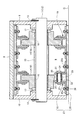
図3に示されるように、前軸11には、軸線方向に所定の間隔を有して一対のスプロケット14、14が装着されるとともに、これらスプロケット14、14の間隔を規制するために両スプロケット14、14の間に位置するように半割カラー15が外嵌されている。
スプロケット14と前軸11との間には、ブッシュ等の軸受16が介挿されており、前軸11に対しスプロケット14が回転自在に支持されている。
スプロケット14と左右の側板9、10との間には、球面座付きのスラストベアリング17が介挿されており、このスラストベアリング17により、スプロケット14から左右の側板9、10に向かって作用するスラスト荷重をスプロケット14の回転運動を阻害することなく受け止めることができるようになっている。
<Description of sprocket>
As shown in FIG. 3, a pair of
A
A thrust bearing 17 with a spherical seat is inserted between the
後軸12の周辺構造は、前軸11のそれと基本的に同じである。このため、前軸11におけるスプロケット14を後軸12においてスプロケット18と称して区別する以外は、図3を援用して重複説明を省略することとする。
また、移動台車4においては、該台車4の中心線を基準に左右に対称構造を呈しているので、以下においては、主に移動台車4の左半分の構造を中心に説明することとし、この説明をもって移動台車4の右半分の構造の説明を行ったものとする。
The peripheral structure of the
In addition, since the
<ローラチェーンの説明>
図4に示されるように、スプロケット14とスプロケット18とには、複数のリンクを環状に連結してなるローラチェーン19が巻き掛け装着されている。
図3に示されるように、ローラチェーン19において、1単位のリンクは、主に左右一対の内側リンクプレート20、20、左右一対の外側リンクプレート21、21、ローラ22、ブッシュ23及びピン24よりなり、一対の内側リンクプレート20、20と一対の外側リンクプレート21、21とを互いの端部同士を内外に重ね合わせるように配し、この重合部分に円筒状のローラ22を配し、このローラ22の中心部を貫通する円筒状のブッシュ23の両端部を一対の内側リンクプレート20、20に圧入するとともに、ローラ22とブッシュ23を貫通するピン24の両端部を一対の外側リンクプレート21、21に圧入し、かしめることにより構成されている。
ローラ22は、ブッシュ23と内側リンクプレート20、20に対し自由に回転可能であり、ブッシュ23と内側リンクプレート20は外側リンクプレート21とピン24に対し自由に回転可能である。
<Description of roller chain>
As shown in FIG. 4, a
As shown in FIG. 3, in the
The
<履板の説明>
図4に示されるように、内側リンクプレート20の接地面側縁部には、外側に水平に張り出すように履板取付プレート20aが一体的に連設されるとともに、外側リンクプレート21の接地面側縁部にも同様に履板取付プレート21aが一体的に連設され、各履板取付プレート20a、21aには、前後方向に幅が狭く左右方向に幅が広い帯状板面を有する履板25がボルト・ナット等の締結具26によって固定されている。
<Description of footwear>
As shown in FIG. 4, a
<履帯の説明>
本実施形態においては、ローラチェーン19と、このローラチェーン19における各リンクに締結される履板25とによって無端状の履帯27が構成され、この履帯27により、地面G上に無限軌道を敷設することができる。
<Description of crawler belt>
In the present embodiment, an
<チェーンガイドの説明>
左側板9には、チェーンガイド28がボルト等の固定手段29によって固定されている。
チェーンガイド28は、前後のスプロケット14、18の間の中央区間のローラチェーン19における上側部分の非接地面側に係合する第1係合部28aと、同区間のローラチェーン19の下側部分の非接地面側に係合する第2係合部28bとを有する板状部材により構成されている。
なお、チェーンガイド28の両側部は、前後のスプロケット14、18との干渉を避けるために、それぞれ円弧状に切り欠かれている。
<Description of chain guide>
A
The
Note that both side portions of the
第1係合部28aは、前後のスプロケット14、18の間において平らで真っ直ぐに延びるような形状とされ、ローラチェーン19における複数のローラ22と同時に接触しながらローラチェーン19が左右に蛇行しないようにその前後方向の運動を案内する役目をする。
第2係合部28bは、前後のスプロケット14、18の間において下に凸の円弧状(台形状等でもよい)の膨らみを持たせた形状とされ、第1係合部28aと同様の案内機能を有するとともに、履帯27を下方に膨出させる役目をする。
The first
The second
<搬送台車の説明>
次に、搬送台車3について図5及び図6を用いて説明する。
なお、搬送台車3は、移動台車4をベースとして構成されるものであるため、移動台車4と同一又は同様のものについては図に同一符号を付すに留めてその詳細な説明を省略することとし、以下においては、移動台車4と異なる点を中心に説明することとする。
<Description of transport cart>
Next, the transport cart 3 will be described with reference to FIGS. 5 and 6.
In addition, since the conveyance trolley | bogie 3 is comprised on the basis of the mobile trolley |
図6に示されるように、後軸30は、例えば、ブッシュ等の軸受31により左側板9及び右側板10にそれぞれ回転自在に支持され、後軸30の一端側は、右側板10の外部に突出されている。
後軸30とその後軸30に装着される各スプロケット18との間には、トルク伝達のためのキー32が介挿されており、後軸30の一端側から入力された回転動力がそのキー32を介してスプロケット18に伝達され、後軸30とスプロケット18とが共に一体となって回転駆動されるようになっている。
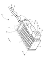
図5に示されるように、台車本体5には、回転駆動装置33が装備されている。この回転駆動装置33は、後軸30の一端部に対し回転動力伝達可能に減速機34を右側板10に取り付けるとともに、この減速機34に対し回転動力伝達可能に電動モータ35を取り付けて構成され、電動モータ35の作動により、電動モータ35からの回転動力を減速機34、後軸30及びキー32(図6参照)を介してスプロケット18に伝達して、スプロケット18を回転駆動することができるようになっている。
As shown in FIG. 6, the
A key 32 for torque transmission is inserted between the
As shown in FIG. 5, the
図5に示されるように、前側板7には、棒状のハンドル36が前方に突出するように取り付けられ、このハンドル36の先端部には、操作箱37が取り付けられている。
操作箱37に装備されたレバーやスイッチ等の操作部37aの操作により、電動モータ35の回転速度や回転方向を制御して、搬送台車3の前後進の切り換えや走行速度の調整を行うことができるようになっている。また、搬送台車3を前進又は後進させながらハンドル36を右方向又は左方向に操作することにより、搬送台車3の操舵を行うことができる。
As shown in FIG. 5, a rod-
The operation speed of the
<作用効果>
以上に述べたように構成される搬送装置1においては、図1、図2及び図5に示されるように、荷物2の前側両角部の左右の搬送台車3、3のそれぞれの履帯27、27の周速度の制御により、直進、操舵及び旋回の各動作を行うことができる。
すなわち、左右の搬送台車3、3における履帯27、27の周速度を同じとすることにより、搬送装置1の直進動作を行うことができる。また、左右の搬送台車3、3における履帯27、27の周速度に差を持たせることにより、その差分に応じて、搬送装置1の操舵動作を行うことができる。また、左右の搬送台車3、3における履帯27、27を互いに逆方向に周回運動させることにより、搬送装置1の旋回動作を行うことができる。
なお、荷物2の後側両角部の左右の移動台車4、4は、搬送台車3、3に従動して走行される。
<Effect>
In the
That is, by making the peripheral speeds of the
Note that the left and right
搬送台車3及び移動台車4が若干の凹凸や段差がある地面G上を走行する際、図4に示される履帯27によって形成される無限軌道が地面Gの凹凸や段差の上に敷設される。このため、各スプロケット14、18の回転運動がその無限軌道上で行われることになり、各スプロケット14、18の回転が地面Gの凹凸や段差で阻害されることがない。
また、荷物2の荷重が前後のスプロケット14、18の間における複数の履板25を介して地面Gに伝えられる。このため、地面Gに対する接地圧を低めることができ、地面Gが軟らかい場合でも、履帯27が地面Gにめり込むのを防ぐことができる。
また、チェーンガイド28の第2係合部28bの膨らみによって履帯27が前後のスプロケット14、18の間で下方に膨出されるので、地面Gに対し履帯27が線状に接地されることになり、各台車3、4の水平回転運動時の摩擦力を低めることができるので、上記の操舵や旋回の各動作を容易に行うことができる。
When the transport carriage 3 and the moving
Further, the load of the
Further, since the
本実施形態の搬送装置1によれば、地面Gに若干の凹凸や段差があったり、地面Gが軟らかかったりするなどの悪条件の地面Gでも、荷物2の搬送動作をスムーズに行うことができる。
According to the
以上、本発明の移動台車及び搬送装置について、一実施形態に基づいて説明したが、本発明は上記実施形態に記載した構成に限定されるものではなく、その趣旨を逸脱しない範囲において適宜その構成を変更することができるものである。 As mentioned above, although the mobile trolley | bogie and conveying apparatus of this invention were demonstrated based on one embodiment, this invention is not limited to the structure described in the said embodiment, The structure is suitably in the range which does not deviate from the meaning. Can be changed.
例えば、上記の実施形態においては、本発明の「第1、第2の車輪」として、ローラ22に噛み合い接触するスプロケット14、18を用いた例を示したが、これらスプロケット14、18に代えて適宜に遊動車輪を用いることができる。
この遊動車輪は、一対の内側リンクプレート20、20の間に嵌り込んでローラ22に転がり接触するリング状突起部を有してなる車輪である。
搬送台車3においては、駆動車輪として機能しているスプロケット18はそのまま用いることとし、従動車輪として機能しているスプロケット14に代えて遊動車輪を用いることができる。
移動台車においては、外部の牽引車(上記の実施形態では搬送台車3)の牽引動作に従って回転運動する意味で従動車輪として機能しているスプロケット14若しくはスプロケット18又は両方のスプロケット14、18に代えて遊動車輪を用いることができる。
For example, in the above embodiment, as the “first and second wheels” of the present invention, the
The idle wheel is a wheel having a ring-shaped protrusion that fits between the pair of
In the transport carriage 3, the
In the mobile carriage, the
本発明の移動台車及び搬送装置は、地面上に無限軌道を敷設することができるとともに、地面に対する接地圧を低めることができるという特性を有していることから、地面に若干の凹凸や段差があったり、地面が軟らかかったりするなどの悪条件の地面での荷物の移動・搬送動作の用途に好適に用いることができる。 Since the mobile carriage and the transport device of the present invention have the characteristics that an endless track can be laid on the ground and the ground pressure against the ground can be lowered, there are some unevenness and steps on the ground. Or can be suitably used for the operation of moving / carrying the luggage on the ground under unfavorable conditions such as the ground being soft.
1 搬送装置
2 荷物
3 搬送台車
4 移動台車
5 台車本体
14、18 スプロケット(第1の車輪、第2の車輪)
19 ローラチェーン
25 履板
28 チェーンガイド
28a 第1係合部
28b 第2係合部
33 回転駆動装置
DESCRIPTION OF
DESCRIPTION OF
Claims (3)
Priority Applications (1)
| Application Number | Priority Date | Filing Date | Title |
|---|---|---|---|
| JP2013079185A JP2014201211A (en) | 2013-04-05 | 2013-04-05 | Movable carriage and transport device |
Applications Claiming Priority (1)
| Application Number | Priority Date | Filing Date | Title |
|---|---|---|---|
| JP2013079185A JP2014201211A (en) | 2013-04-05 | 2013-04-05 | Movable carriage and transport device |
Publications (1)
| Publication Number | Publication Date |
|---|---|
| JP2014201211A true JP2014201211A (en) | 2014-10-27 |
Family
ID=52352042
Family Applications (1)
| Application Number | Title | Priority Date | Filing Date |
|---|---|---|---|
| JP2013079185A Pending JP2014201211A (en) | 2013-04-05 | 2013-04-05 | Movable carriage and transport device |
Country Status (1)
| Country | Link |
|---|---|
| JP (1) | JP2014201211A (en) |
Cited By (1)
| Publication number | Priority date | Publication date | Assignee | Title |
|---|---|---|---|---|
| JP2017226245A (en) * | 2016-06-20 | 2017-12-28 | 株式会社 イーサム | Manual carrier and caterpillar traveling device used therefor |
-
2013
- 2013-04-05 JP JP2013079185A patent/JP2014201211A/en active Pending
Cited By (1)
| Publication number | Priority date | Publication date | Assignee | Title |
|---|---|---|---|---|
| JP2017226245A (en) * | 2016-06-20 | 2017-12-28 | 株式会社 イーサム | Manual carrier and caterpillar traveling device used therefor |
Similar Documents
| Publication | Publication Date | Title |
|---|---|---|
| CN100443351C (en) | Small six-track all-terrain mobile robot | |
| US11130519B1 (en) | Parallel maneuvering system | |
| EP2024223B1 (en) | Snow traction unit for vehicles | |
| JP5666119B2 (en) | Traveling robot | |
| US11091022B2 (en) | Centreless wheel with drive | |
| WO2002046031A1 (en) | Remote-operated multi-directional transport vehicle | |
| KR20150014057A (en) | Omni-directional caterpillar tracks and omni-directional moving vehicle using thereof | |
| TW201544380A (en) | Vehicle track assembly having tapered wheels | |
| CN107776692A (en) | Mobile robot and its mode of progression | |
| CN205112850U (en) | Single wheel universal wheel | |
| EP2983970B1 (en) | Vehicle four-wheel drive system | |
| CN109094671B (en) | Additional crawler system with wheel forward and reverse converter and wheeled vehicle | |
| CN110143236B (en) | A synchronous steering chassis structure for AGV | |
| US7921942B2 (en) | Amphibious all terrain vehicle with track assemblies | |
| US10906600B2 (en) | Traveling apparatus | |
| JP2014201211A (en) | Movable carriage and transport device | |
| CN114013214B (en) | An active omnidirectional wheel and its movement method | |
| JP2010012971A (en) | Screw shaft for driving conveying truck | |
| JP3782977B2 (en) | Crawler type traveling device | |
| CN215626476U (en) | Wheel train structure and AGV device | |
| JP5984737B2 (en) | Crawler travel device | |
| JP3828823B2 (en) | Crawler type traveling device | |
| JP5773861B2 (en) | Semi-crawler tractor | |
| JP6021735B2 (en) | Crawler travel device | |
| JP7394698B2 (en) | Rubber crawler starting wheel, drive mechanism, and vehicle |