JP2014235902A - Poe standard conforming connector and lan cable - Google Patents
Poe standard conforming connector and lan cable Download PDFInfo
- Publication number
- JP2014235902A JP2014235902A JP2013117081A JP2013117081A JP2014235902A JP 2014235902 A JP2014235902 A JP 2014235902A JP 2013117081 A JP2013117081 A JP 2013117081A JP 2013117081 A JP2013117081 A JP 2013117081A JP 2014235902 A JP2014235902 A JP 2014235902A
- Authority
- JP
- Japan
- Prior art keywords
- lan cable
- contact portion
- cable
- terminal
- connector
- Prior art date
- Legal status (The legal status is an assumption and is not a legal conclusion. Google has not performed a legal analysis and makes no representation as to the accuracy of the status listed.)
- Pending
Links
- 239000002184 metal Substances 0.000 claims abstract description 7
- 238000004891 communication Methods 0.000 claims description 9
- 238000005452 bending Methods 0.000 claims description 8
- 230000005611 electricity Effects 0.000 abstract description 5
- 230000005540 biological transmission Effects 0.000 description 10
- 239000012212 insulator Substances 0.000 description 8
- 238000000034 method Methods 0.000 description 3
- 238000010295 mobile communication Methods 0.000 description 3
- 239000011347 resin Substances 0.000 description 3
- 229920005989 resin Polymers 0.000 description 3
- 230000020169 heat generation Effects 0.000 description 2
- WABPQHHGFIMREM-UHFFFAOYSA-N lead(0) Chemical compound [Pb] WABPQHHGFIMREM-UHFFFAOYSA-N 0.000 description 2
- 230000003321 amplification Effects 0.000 description 1
- 239000011810 insulating material Substances 0.000 description 1
- 238000012423 maintenance Methods 0.000 description 1
- 238000003199 nucleic acid amplification method Methods 0.000 description 1
Images




Landscapes
- Connections By Means Of Piercing Elements, Nuts, Or Screws (AREA)
- Connector Housings Or Holding Contact Members (AREA)
Abstract
Description
本発明は、PoE規格対応コネクタ及びLANケーブルに関する。 The present invention relates to a PoE standard compatible connector and a LAN cable.
PoE規格対応コネクタであるRJ45プラグコネクタ(8極8芯モジュラコネクタとも呼ばれる。)が知られている。そして、PoE規格対応コネクタであるRJ45プラグコネクタは、LANケーブル(UTPケーブル(Unshielded Twist Pair cable))と屋外防水送信増幅装置とを接続することにより、移動通信基地局からLANケーブル(UTPケーブル)を介して屋外防水送信増幅装置に、Ethernet(登録商標)信号を送信するとともに、LANケーブル(UTPケーブル)を介して当該屋外防水送信増幅装置が動作するために必要な電気を供給する。具体的には、当該RJ45プラグコネクタは、RJ45プラグコネクタ内部の鋭利な先端を持つ端子をLANケーブル(UTPケーブル)内の電線に串刺しすることにより、電線の芯線と端子とを圧接させている。
しかしながら、温度サイクルや圧接部分の発熱等の影響により、LANケーブル(UTPケーブル)の絶縁体(樹脂)が縮小固形化する。これにより、LANケーブル(UTPケーブル)とRJ45プラグコネクタとの接続部分において、電線の芯線と端子との圧接部分に隙間が生じ、接触抵抗が増加して発熱してしまうという問題がある。
An RJ45 plug connector (also called an 8-pole 8-core modular connector) that is a PoE standard compliant connector is known. The RJ45 plug connector, which is a PoE standard connector, connects a LAN cable (UTP cable) from a mobile communication base station by connecting a LAN cable (UTP cable (Unshielded Twist Pair cable)) and an outdoor waterproof transmission amplifier. An Ethernet (registered trademark) signal is transmitted to the outdoor waterproof transmission amplifier via the LAN cable, and electricity necessary for the outdoor waterproof transmission amplifier is operated via a LAN cable (UTP cable). Specifically, in the RJ45 plug connector, a terminal having a sharp tip inside the RJ45 plug connector is skewed into an electric wire in a LAN cable (UTP cable), thereby pressing the core wire of the electric wire and the terminal.
However, the insulator (resin) of the LAN cable (UTP cable) is reduced and solidified due to the influence of the temperature cycle, heat generation at the pressure contact portion, and the like. Thereby, in the connection part of a LAN cable (UTP cable) and a RJ45 plug connector, a clearance gap arises in the press-contact part of the core wire and terminal of an electric wire, and there exists a problem that contact resistance increases and it generate | occur | produces heat.
特許文献1は、弾性片部を有する電線保持部を開示している。弾性片部は、電線保持部の左右の側壁の端部をそれぞれ内側へ折り返すことにより形成されている。そして、それぞれの折り返し部分の先端が電線に食い込むことにより、電線保持部と電線とが電気的に接続されるようになっている。
また、特許文献2は、一対の電極配線体を有するプラグを開示している。一対の電極配線体は、それぞれ導電性金属板からなり、先端部にY字状の切り込み(スリット)が設けられている。そして、当該電極配線体のY字状の切り込みにリード線を挟み込み、当該電極配線体とリード線の芯線とが電気的に接続されるようになっている。
また、特許文献3は、一対の接触部を有するランプソケットを開示している。一対の接触部は、U字状に屈曲した導電性金属板からなり、当該一対の接触部の間に電極部が挟持されることにより、当該接触部と電極部とが電気的に接続するようになっている。
しかしながら、特許文献1に記載の弾性片部は、その先端が電線に食い込むことにより、電線保持部と電線とが電気的に接続するものであるため、電線の絶縁体(樹脂)が経年変化することにより、接触抵抗が増加する虞がある。また、特許文献2に記載のプラグはコンセントに電気的に接続されるプラグについての技術であり、LANケーブル内の電線とPoE規格対応コネクタとの電気的接続にそのまま応用することは難しい。同様に、特許文献3に記載の技術は、ランプソケットの接触部と電極との電気的接続に関する技術であり、LANケーブル内の電線とPoE規格対応コネクタとの電気的接続にそのまま応用することは難しい。
However, since the elastic piece portion described in
本発明の第1の態様にかかるPoE規格対応コネクタは、LANケーブル内の電線の芯線と電気的に接続する端子部を備える。また、前記端子部は、導電性金属板から形成されており、前記端子部の一方の端部に前記芯線に接続する電線接続部を備える。また、前記電線接続部は、第1の接触部と第2の接触部とを備える。また、前記第1の接触部と前記第2の接触部は、前記端子部の前記一方の端部が二股に分かれて延出した後、前記端子部の幅方向内側に屈曲してなる略U字状の部材であり、前記第1の接触部と前記第2の接触部との間の距離は、前記電線の径より小さい。 The PoE standard-compliant connector according to the first aspect of the present invention includes a terminal portion that is electrically connected to a core wire of an electric wire in a LAN cable. Moreover, the said terminal part is formed from the electroconductive metal plate, and is equipped with the electric wire connection part connected to the said core wire in one edge part of the said terminal part. Moreover, the said electric wire connection part is provided with the 1st contact part and the 2nd contact part. Further, the first contact portion and the second contact portion are substantially U formed by bending the one end portion of the terminal portion into two branches and then bending the terminal portion in the width direction. It is a letter-shaped member, The distance between the said 1st contact part and the said 2nd contact part is smaller than the diameter of the said electric wire.
本発明の第2の態様にかかるLANケーブルは、上記PoE規格対応コネクタを備える。 A LAN cable according to a second aspect of the present invention includes the PoE standard compliant connector.
本発明により、より安定的にEthernet信号及び電気を供給することができるPoE規格対応コネクタ及びLANケーブルを提供することができる。 According to the present invention, it is possible to provide a PoE standard compliant connector and a LAN cable that can supply an Ethernet signal and electricity more stably.
以下、本発明を適用可能な実施の形態について説明する。なお、本発明は、下記の実施の形態に限定されるものではない。
実施の形態1.
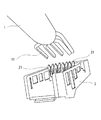
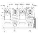
図1に、本発明の実施の形態1にかかるLANケーブル1及びPoE規格対応コネクタ2を示す。また、図2、図3に、LANケーブルとPoE規格対応コネクタとの接続部分を示す。また、図4に、図3の破線で囲んだ部分を拡大して示す。
Embodiments to which the present invention can be applied will be described below. In addition, this invention is not limited to the following embodiment.
FIG. 1 shows a
図1〜図4に示すように、LANケーブル1は、PoE規格対応コネクタ2を備えるものである。また、LANケーブル1は、UTPケーブル(Unshielded Twist Pair cable)等の通信用ケーブルである。具体的には、LANケーブル1の内部には、電線11が内蔵されている。電線11は、芯線111、絶縁体112を備え、チューブ状の絶縁体112に芯線111が挿通している。絶縁体112は、樹脂等の絶縁材料から形成されている。
As shown in FIGS. 1 to 4, the
PoE規格対応コネクタ2は、例えば、RJ45プラグコネクタ等である。また、PoE規格対応コネクタ2は、LANケーブル1と屋外防水送信増幅装置(通信装置)とを接続する。そして、PoE規格対応コネクタ2は、移動通信基地局からLANケーブル1を介して屋外防水送信増幅装置に、Ethernet信号を送信するとともに、LANケーブルを介して当該屋外防水送信増幅装置が動作するために必要な電気を供給する。
The PoE standard
また、PoE規格対応コネクタ2は、LANケーブル1内の電線11の芯線111と電気的に接続する端子部21を備える。
端子部21は、導電性金属板から形成されている。また、端子部21は、端子部21の一方の端部に、LANケーブル1内の電線11の芯線111と電気的に接続する電線接続部211を備える。また、端子部21は、端子部21の他方の端部に、屋外防水送信増幅装置(通信装置)と電気的に接続する通信装置接続部212を備える。
The PoE standard
The
また、電線接続部211は、略M字状の板ばねとなっている。
具体的には、電線接続部211は、第1の接触部213と第2の接触部214とを備える。そして、第1の接触部213と第2の接触部214は、端子部21の上記一方の端部が二股に分かれて延出した後、端子部21の幅方向内側に屈曲してなる略U字状の部材となっている。換言すれば、略U字状の第1の接触部213と第2の接触部214とが向き合うように配置されることにより、第1の接触部213と第2の接触部214は、略M字状の板ばねを形成している。
Moreover, the electric
Specifically, the
また、第1の接触部213と第2の接触部214との間の距離は、LANケーブル1の電線11の径より小さくなっている。そのため、図3、図4に示すように、第1の接触部213と第2の接触部214との間に挟持された電線11は、第1の接触部213と第2の接触部214とからなる板ばねの弾性力により、圧接される。換言すれば、第1の接触部213と第2の接触部214との間に圧接された電線11は、第1の接触部213と第2の接触部214とからなる板ばねの弾性力により潰れ、芯線111と第1の接触部213及び第2の接触部214とが電気的に接続する。
Further, the distance between the
また、電線11は、第1の接触部213の平面部と第2の接触部214の平面部との間に圧接される。そのため、電線11の絶縁体112が経年変化して縮小固形化しても、芯線111と第1の接触部213及び第2の接触部214との電気的な接続状態に影響が生じない。
Further, the
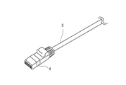
図5に、従来のLANケーブル3及びRJ45プラグコネクタ(8極8芯モジュラコネクタとも呼ばれる。)4を示す。また、図6に、RJ45プラグコネクタ4の正面図を示す。また、図7、図8に、図6の破線で囲む部分を拡大して示す。図5〜図7に示すように、RJ45プラグコネクタ4は、棒状の端子部41を備える。また、端子部41は、鋭利な先端411を有している。
FIG. 5 shows a
そして、図7に示すように、端子部41の鋭利な先端411をLANケーブル3の電線31に串刺しする。これにより、電線31の芯線311と端子部41とが電気的に接続する。
Then, as shown in FIG. 7, the sharp tip 411 of the
しかしながら、従来にかかるRJ45プラグコネクタ4では、端子41が電線31に串刺しするため、図8に示すように、電線31の絶縁体312が経年変化して縮小固形化すると、端子部41と電線31の芯線311との間に隙間Xが生じ、端子部41と電線31との接触抵抗が増加し、発熱の原因となる。
However, in the
従来にかかるRJ45プラグコネクタに対し、本発明の実施の形態1にかかるPoE規格対応コネクタ2及びLANケーブル1においては、LANケーブル1内の電線11の芯線111と電気的に接続する端子部21を備える。また、端子部21は、導電性金属板から形成されており、端子部21の一方の端部に芯線111に接続する電線接続部211を備える。また、電線接続部211は、第1の接触部213と第2の接触部214とを備える。また、第1の接触部213と第2の接触部214は、端子部21の上記一方の端部が二股に分かれて延出した後、端子部21の幅方向内側に屈曲してなる略U字状の部材である。そして、第1の接触部213と第2の接触部214との間の距離は、電線11の径より小さい。
In contrast to the conventional RJ45 plug connector, in the PoE standard
そのため、第1の接触部213と第2の接触部214との間に圧接された電線11は、第1の接触部213と第2の接触部214とからなる板ばねの弾性力により潰れ、芯線111と第1の接触部213及び第2の接触部214とが電気的に接続する。また、電線11は、第1の接触部213の平面部と第2の接触部214の平面部との間に圧接される。これにより、電線11の絶縁体112が経年変化して縮小固形化しても、芯線111と第1の接触部213及び第2の接触部214との電気的な接続状態に影響が生じない。
Therefore, the
また、端子部21の他方の端部は、LANケーブル1がPoE規格対応コネクタ2を介して接続する屋外防水送信増幅装置(通信装置)と、端子部21とを電気的に接続する通信装置接続部212を備える。
これにより、PoE規格対応コネクタ2は、移動通信基地局からLANケーブル1を介して屋外防水送信増幅装置に、Ethernet信号を送信するとともに、LANケーブルを介して当該屋外防水送信増幅装置が動作するために必要な電気を供給することができる。
The other end of the
As a result, the PoE standard
なお、本発明は上記実施の形態に限られたものではなく、趣旨を逸脱しない範囲で適宜変更することが可能である。 Note that the present invention is not limited to the above-described embodiment, and can be changed as appropriate without departing from the spirit of the present invention.
1 LANケーブル
11 電線
111 芯線
112 絶縁体
2 PoE規格対応コネクタ
21 端子部
211 電線接続部
212 通信装置接続部
213 第1の接触部
214 第2の接触部
DESCRIPTION OF
Claims (3)
前記端子部は、導電性金属板から形成されており、前記端子部の一方の端部に前記芯線に接続する電線接続部を備え、
前記電線接続部は、第1の接触部と第2の接触部とを備え、
前記第1の接触部と前記第2の接触部は、前記端子部の前記一方の端部が二股に分かれて延出した後、前記端子部の幅方向内側に屈曲してなる略U字状の部材であり、
前記第1の接触部と前記第2の接触部との間の距離は、前記電線の径より小さい、PoE規格対応コネクタ。 It has a terminal part that is electrically connected to the core wire of the cable in the LAN cable,
The terminal portion is formed of a conductive metal plate, and includes an electric wire connection portion connected to the core wire at one end portion of the terminal portion,
The wire connecting portion includes a first contact portion and a second contact portion,
The first contact portion and the second contact portion are substantially U-shaped formed by bending the one end portion of the terminal portion into two branches and then bending inward in the width direction of the terminal portion. It is a member of
The PoE standard compliant connector, wherein a distance between the first contact portion and the second contact portion is smaller than a diameter of the electric wire.
Priority Applications (1)
| Application Number | Priority Date | Filing Date | Title |
|---|---|---|---|
| JP2013117081A JP2014235902A (en) | 2013-06-03 | 2013-06-03 | Poe standard conforming connector and lan cable |
Applications Claiming Priority (1)
| Application Number | Priority Date | Filing Date | Title |
|---|---|---|---|
| JP2013117081A JP2014235902A (en) | 2013-06-03 | 2013-06-03 | Poe standard conforming connector and lan cable |
Publications (1)
| Publication Number | Publication Date |
|---|---|
| JP2014235902A true JP2014235902A (en) | 2014-12-15 |
Family
ID=52138455
Family Applications (1)
| Application Number | Title | Priority Date | Filing Date |
|---|---|---|---|
| JP2013117081A Pending JP2014235902A (en) | 2013-06-03 | 2013-06-03 | Poe standard conforming connector and lan cable |
Country Status (1)
| Country | Link |
|---|---|
| JP (1) | JP2014235902A (en) |
Cited By (1)
| Publication number | Priority date | Publication date | Assignee | Title |
|---|---|---|---|---|
| WO2019159763A1 (en) * | 2018-02-13 | 2019-08-22 | 株式会社ベガシステムズ | Method for manufacturing connector-attached cable |
-
2013
- 2013-06-03 JP JP2013117081A patent/JP2014235902A/en active Pending
Cited By (2)
| Publication number | Priority date | Publication date | Assignee | Title |
|---|---|---|---|---|
| WO2019159763A1 (en) * | 2018-02-13 | 2019-08-22 | 株式会社ベガシステムズ | Method for manufacturing connector-attached cable |
| JP2019139981A (en) * | 2018-02-13 | 2019-08-22 | 株式会社ベガシステムズ | Method for manufacturing cable with connector |
Similar Documents
| Publication | Publication Date | Title |
|---|---|---|
| WO2008045191A3 (en) | Electrical terminal with high conductivity core | |
| ATE550808T1 (en) | MODULAR CONNECTOR ASSEMBLY, TERMINATED CABLE ASSEMBLY AND PRODUCTION METHOD THEREOF | |
| WO2009120955A3 (en) | An electrical cable harness and assembly for transmitting ac electrical power | |
| CN203932413U (en) | SATA electric connector and electric connector combination | |
| MX2011013066A (en) | Electrically heatable media line and line connector. | |
| JP2012209255A (en) | Usb connector | |
| CN203119137U (en) | Electric connector, electric connector assembly and terminal | |
| CN102623825B (en) | Audio connector | |
| CN104160564A (en) | Connector with wireless control | |
| US9705308B2 (en) | Power strip, power plug, and power outlet | |
| CN104348051B (en) | Micro coaxial cable connector assembly | |
| CN204651522U (en) | A kind of electric connector and electric connector cable assembly | |
| TW201145684A (en) | Electric connector and electric connector unit | |
| CN203521687U (en) | Terminal and electrical connector including the terminal | |
| DE60127600D1 (en) | wire tap | |
| CN107346844B (en) | Connection terminal and electric connector | |
| JP6329183B2 (en) | Spring clip and connection box | |
| CN203942492U (en) | Photovoltaic junction box | |
| ATE472188T1 (en) | CONDUCTIVE DEVICE FOR ELECTRICAL CONTACT OF A CONDUCTOR SHIELD SHEATH | |
| WO2009074197A3 (en) | Electrical plug connector | |
| CN102623850B (en) | Audio connector | |
| JP5307656B2 (en) | connector | |
| CN107069285B (en) | Male connector and data line | |
| CN100578872C (en) | Active conduction structure between electrical signal modules | |
| DE502006000343D1 (en) | Socket for telecommunication and data transmission systems |