JP2015083473A - Packaging container - Google Patents
Packaging container Download PDFInfo
- Publication number
- JP2015083473A JP2015083473A JP2013216198A JP2013216198A JP2015083473A JP 2015083473 A JP2015083473 A JP 2015083473A JP 2013216198 A JP2013216198 A JP 2013216198A JP 2013216198 A JP2013216198 A JP 2013216198A JP 2015083473 A JP2015083473 A JP 2015083473A
- Authority
- JP
- Japan
- Prior art keywords
- piece
- packaging container
- lid
- sliding
- side plate
- Prior art date
- Legal status (The legal status is an assumption and is not a legal conclusion. Google has not performed a legal analysis and makes no representation as to the accuracy of the status listed.)
- Granted
Links
Images


Landscapes
- Cartons (AREA)
Abstract
【課題】差込片のない蓋部が、開口部を塞いだ状態で保持されるように構成すること。
【解決手段】本体構成板10によって形成された開口部OPを蓋部片20にて覆うことで内容物を包装する包装容器1であって、本体構成板10のうち蓋部片20に連結される背面側板12と、背面側板12の内側近傍に形成される隙間部形成片16と、蓋部片20の内側に連結される背面側板12と隙間部形成片16との間に形成された隙間Sを摺動する摺動片42と、を有することを特徴とする包装容器1。
【選択図】図4An object of the present invention is to configure a lid without an insertion piece so as to be held in a state where an opening is closed.
A packaging container (1) for packaging contents by covering an opening (OP) formed by a body constituting plate (10) with a lid piece (20), and is connected to the lid piece (20) of the body constituting plate (10). The back side plate 12, the gap forming piece 16 formed near the inside of the back side plate 12, and the gap formed between the back side plate 12 and the gap forming piece 16 connected to the inside of the lid piece 20. A packaging container 1 having a sliding piece 42 that slides on S.
[Selection] Figure 4
Description
本発明は、本体構成片によって形成された開口部を蓋部片にて覆うことで内容物を包装する包装容器に関する。 The present invention relates to a packaging container for packaging contents by covering an opening formed by a main body component piece with a lid piece.
紙製の包装容器で、本体構成片によって形成された開口部を蓋部片にて覆うことで内容物を包装するものがある(例えば、特許文献1参照)。 There is a paper packaging container that wraps contents by covering an opening formed by a main body component piece with a lid piece (see, for example, Patent Document 1).
特許文献1の包装容器は、容器側部によって囲まれて形成される開口部を塞ぐため、蓋部材(第一蓋部材)に差込片を連結している。この構成で、差込片と容器側部の内面との摩擦、及び差込片と蓋部保持片との係合とにより、蓋部材が前記開口部に対して塞いだ状態で保持する。このように、従来の構成では、開口部を塞いだ状態で蓋部材を保持するためには、差込片が必須であった。
The packaging container of
しかしながら、蓋部材を保持するために差込片が必須であるとすると、包装容器の構成するにあたりデザインの制約を課すことになっていた。 However, if an insertion piece is essential to hold the lid member, design restrictions are imposed on the construction of the packaging container.
このため、本発明の目的は、差込片のない蓋部が、開口部を塞いだ状態で保持されるように構成することである。 For this reason, the objective of this invention is comprising so that the cover part without an insertion piece may be hold | maintained in the state which plugged up the opening part.
上記目的を達成するための本発明の第1の構成は、本体構成板によって形成された開口部を蓋部片にて覆うことで内容物を包装する包装容器であって、本体構成板のうち前記蓋部片に連結される蓋部連結片と、前記蓋部連結片の内側近傍に形成される隙間部形成片と、前記蓋部片の内側に連結される前記蓋部連結片と前記隙間部形成片との間に形成された隙間を摺動する摺動片と、を有することを特徴とする包装容器である。 A first configuration of the present invention for achieving the above object is a packaging container for packaging contents by covering an opening formed by a main body constituent plate with a lid piece, and among the main constituent plates A lid connecting piece connected to the lid piece, a gap forming piece formed near the inside of the lid connecting piece, the lid connecting piece connected to the inside of the lid piece, and the gap It is a packaging container characterized by having a sliding piece which slides in a gap formed between the part forming pieces.
本発明の第2の構成は、前記摺動片には制御片が連結され、前記本体構成板には前記制御片を露出可能な窓部が形成され、前記窓部から露出した前記制御片の一部を外部へ起き上がらせることで前記蓋部片をロックすることを特徴とする第1の構成に記載の包装容器である。 According to a second configuration of the present invention, a control piece is connected to the sliding piece, a window part capable of exposing the control piece is formed on the main body constituting plate, and the control piece exposed from the window part is formed. The packaging container according to the first configuration, wherein the lid piece is locked by raising a part to the outside.
本発明の第3の構成は、前記摺動片は摺動方向に沿ってリブが形成されることを特徴とする第1の構成または第2の構成に記載の包装容器である。 A third configuration of the present invention is the packaging container according to the first configuration or the second configuration, wherein the sliding piece has a rib formed along a sliding direction.
上記構成にしたことにより、差込片のない蓋部であっても開口部を塞いだ状態で保持される。 With the above configuration, even the lid portion without the insertion piece is held in a state where the opening portion is closed.
具体的には、第1の構成によれば、蓋部片を180°の状態から90°の状態にする過程において、摺動片が蓋部連結片と隙間部形成片との間に形成された隙間を摺動する。これにより、摺動片の隙間における摩擦により、開口を開放された状態から閉塞した状態までの任意の位置において、蓋部片の姿勢を保持することができる。 Specifically, according to the first configuration, the sliding piece is formed between the lid connecting piece and the gap forming piece in the process of changing the lid piece from the 180 ° state to the 90 ° state. Slide through the gap. Thereby, the attitude | position of a cover part piece can be hold | maintained in the arbitrary positions from the state by which the opening was obstruct | occluded by the friction in the clearance gap between sliding pieces.
第2の構成によれば、窓部から露出した制御片の一部を外部へ起き上がらせることで蓋部片をロックすることができる。 According to the second configuration, the lid piece can be locked by raising a part of the control piece exposed from the window portion to the outside.
第3の構成によれば、リブを形成して補強することで、紙のようにクセが付きやすい素材であっても、長い期間、摺動片に円滑な摺動動作を行わせることができる。 According to the 3rd structure, even if it is a material which is easy to get a habit like paper like by forming a rib and reinforcing, it can make a sliding piece perform smooth sliding operation for a long period of time. .
〔第1実施形態〕
(包装容器1の構成)
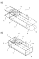
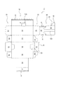
図を用いて第1実施形態の包装容器1を説明する。図1は第1実施形態の包装容器の展開図である。(a)がブランク板表面、すなわち容器の外部側から見た面の展開図である。図2は第1実施形態の包装容器の組立時の状態を説明する斜視図である。
[First Embodiment]
(Configuration of packaging container 1)
The
包装容器1は、図1に示す一枚のブランク板を折りたたむことで形成される。包装容器1は、図2に示すように、連続する側板を折りたたんで内容物の収納空間を形成する本体構成板10と、本体構成板10によって囲まれることで形成される開口部OPを覆う蓋部片20と、底部30と、摺動部40を有する。
The
図1の展開図を用いて、包装容器1の各部構成を説明する。本体構成板10は、折り目を介して連続して形成される、右側板11、背面側板12(蓋部連結片)、左側板13、正面側板14、右内部側板15、隙間部形成片16、隙間部固定片17を有する。なお、正面側板14は切離線D1において切り離し可能である。
Each part structure of the
蓋部片20は、本体構成板10に連結される摺動部連結片21、側片22、蓋部天面片23、側片24、から構成される。蓋部天面片23の内部側には接着剤Gが配設される。
The
底部30は、固定片31、側片32、被固定片33、側片34、から構成される。なお、底部30の接着剤Gは省略するが、固定片31と被固定片33とは互いに接着固定される。
The
摺動部40は、摺動部連結片21に連結される摺動部固定片41と、摺動片42、とが折り目を介して連続して形成される。なお、摺動部固定片41と摺動片42との間には、折目Aと切込Dが形成され、折目Aのみで一部つながっている。また、摺動片42は後述の摺動方向に沿ってリブ42aが形成される。なお、リブ42aは、エンボス加工をすることで形成することが好ましい。
In the
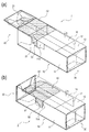
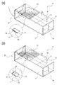
次に、包装容器1の組立ての際の特徴について、図2及び図3を用いて説明する。図3は第1実施形態の包装容器の組立時・完成時の内部状態を説明する斜視図である。図3は、説明のために全ての片を透明にして説明している。なお、組立作業は自動包装によって行われる。
Next, the characteristics when the
まず、図2に示すように、摺動部連結片21と摺動部固定片41との間で折ることにより、摺動部40を形成する(図2(a)参照)。
First, as shown in FIG. 2, the
そして、本体構成板10を形成するため、隙間部固定片17、隙間部形成片16、右内部側板15を折り、隙間部固定片17を左側板13に接着固定する。この際、本体構成板10の内部で、背面側板12の内側近傍に形成される隙間部形成片16と背面側板12との間に隙間Sができるように接着固定する(図2(b)参照)。
In order to form the main
そして、右側板11が右内部側板15上に重なるように、左側板13、背面側板12、右側板11を折りつつ、右側板11の接着剤Gによって、右側板11を右内部側板15に対して固定する(図3(a)参照)。
Then, the
そして、本体構成板10によって形成された開口部OPを閉塞するために、蓋部片20と底部30とを閉じる。この際、摺動部40の摺動片42が蓋部片20の内側に連結される背面側板12と隙間部形成片16との間に形成された隙間Sに入り込む。
Then, in order to close the opening OP formed by the main
なお、本実施形態における組立手順は、あくまでも構成を説明するためのものであって、これに限られるものではない。特に、自動包装においては、より効率の良い他の手順で組み立てることは可能である。 In addition, the assembly procedure in this embodiment is only for demonstrating a structure, and is not restricted to this. In particular, in automatic packaging, it is possible to assemble with other procedures that are more efficient.
(包装容器1の使用状態)
図4を用いて包装容器1の使用状態を説明する。図4は第1実施形態の包装容器の動作を説明する概略断面図である。
(Use condition of packaging container 1)
The use state of the
図4(a)に示すように、蓋部片20を開けた状態において、摺動部40の摺動片42は、蓋部片20の内側に連結される背面側板12と隙間部形成片16との間に形成された隙間Sに入り込んでいる。このため、摺動片42は、蓋部片20を動かす際に、背面側板12と隙間部形成片16との間に形成された隙間Sにて摺動することとなる。
As shown in FIG. 4A, in the state where the
これにより、蓋部片20を180°の状態(図4(a)参照)から90°の状態(図4(d)参照)にする過程において、摺動片42は、隙間Sにおいて摺動されることとなる。このように、摺動片42の隙間Sにおける摩擦により、開口部OPを開放された状態(図4(a)〜(c)の状態)から閉塞した状態(図4(d)の状態)までの任意の位置において、蓋部片20の姿勢を保持することができる。
Thereby, the sliding
この際、摺動片42にリブ42aが形成されることで、摺動片42は補強されるため、紙のようにクセが付きやすい素材であっても、長い期間、摺動片42に円滑な摺動動作を行わせることができる。
At this time, since the
〔第2実施形態〕
(包装容器2の構成)
図を用いて第2実施形態の包装容器2を説明する。図5は第2実施形態の包装容器の展開図である。(a)がブランク板表面、すなわち容器の外部側から見た面の展開図である。図6は第2実施形態の包装容器の組立時・完成時の内部状態を説明する斜視図である。図6以降は、説明のために全ての片を透明にして説明している。前述の実施形態と同様の構成については、同符号を付し説明を省略する。
[Second Embodiment]
(Configuration of packaging container 2)
The
包装容器2の展開図(図5)に示すように、摺動片42には摺動片42の側方に突出する制御片50が連結され、本体構成板10の右側板11には、制御片50を露出可能な窓部11Aが形成される。
As shown in the development view of the packaging container 2 (FIG. 5), a
包装容器2を折り畳んで組み立てると、図6に示すように、制御片50が右側板11の窓部11Aから露出する。
When the
そして、図6(b)に示す完成時に、制御片50のうち起き上げることが可能な起上部51も窓部11Aから露出する。
When the completion shown in FIG. 6B is completed, the raised
(包装容器2の使用状態)
図7を用いて包装容器2の使用状態を説明する。図7は第2実施形態の包装容器の動作を説明する斜視図である。
(Use condition of packaging container 2)
The use state of the
図7(a)に示すように、蓋部片20を開けた状態において、摺動部40の摺動片42は、蓋部片20の内側に連結される背面側板12と隙間部形成片16との間に形成された隙間Sに入り込んでいる。このため、蓋部片20を閉じる過程において、摺動片42は隙間Sにて摺動する。また、この状態において、制御片50は、右側板11と右内部側板15との間で挟持される。
As shown in FIG. 7A, in the state where the
蓋部片20を閉じた状態(図7(b)参照)において、窓部11Aから露出した制御片50の起上部51を外部へ起き上げると、起上部51が窓部11Aと係合する。すると、制御片50の位置が固定され、制御片50と連結している摺動部40、更には摺動部40と連結している蓋部片20の位置も固定される。これにより、蓋部片20を閉じた状態でロックすることができる。
When the raised
制御片50によって、蓋部片20を閉じた状態でロックすることが可能になる。このように、チャイルドロック機能を付帯することで、包装容器2の安全性を高めることができる。
The
〔第3実施形態〕
(包装容器3の構成)
図を用いて第3実施形態の包装容器3を説明する。図8は第3実施形態の包装容器の展開図である。図9は第3実施形態の包装容器の完成時・開閉時の内部状態を説明する斜視図であり、(a)が蓋部片20を閉めた状態であり、(b)が蓋部片20を開けた状態である。図10は第3実施形態の包装容器の摺動片の固定動作を説明する斜視図であり、(a)が制御片60を起こす前の状態、(b)が制御片60を起こした状態を示す。
[Third Embodiment]
(Configuration of packaging container 3)
The
図9及び図10は、説明のために全ての片を透明にして説明している。また摺動片42は動作時の姿勢を明確にするため網掛けしている。前述の実施形態と同様の構成については、同符号を付し説明を省略する。
In FIGS. 9 and 10, for the sake of explanation, all the pieces are described as being transparent. The sliding
包装容器3の展開図(図8)に示すように、摺動片42には切離線D60と折目を介して区分される制御片60が形成される。一方、本体構成板10の右側板11には、制御片60を露出可能な窓部11Bが形成される。
As shown in the development view of the packaging container 3 (FIG. 8), the sliding
包装容器3を折り畳んで組み立てると、図9(a)に示すように、摺動片42のうち、制御片60の部分が右側板11の窓部11Bから露出する。図9(b)に示すように、蓋部片20を開放すると、摺動片42及び制御片60は、背面側板12と隙間部形成片16との間の隙間Sにおいてスライド移動する。
When the
(包装容器3の摺動片42の固定動作)
図10(a)に示すように、蓋部片20を閉じた状態においては、制御片60が窓部11Bから露出する。
(Fixing operation of the sliding
As shown in FIG. 10A, the
この状態で、制御片60を外部へ起き上げると、制御片60が窓部11Bと係合する。すると、制御片60の位置が固定され、制御片60と連結している摺動部40、更には摺動部40と連結している蓋部片20の位置も固定される。これにより、蓋部片20を閉じた状態でロックすることができる。
In this state, when the
本実施形態においても、制御片60によって、蓋部片20を閉じた状態でロックすることが可能になる。このように、チャイルドロック機能を付帯することで、包装容器3の安全性を高めることができる。
Also in the present embodiment, the
また、本実施形態では、制御片60が摺動片42と同一平面に形成される。このような構成であると、蓋部片20の開閉の際に、蓋部片20と連動して動く摺動片42の隙間Sにおける摺動がより円滑に行われる。このため、蓋部片20の開閉動作がより円滑なものとなる。
In the present embodiment, the
A…折目、D…切込、D1…切離線、D60…切離線、G…接着剤、OP…開口部、S…隙間、1…包装容器、2…包装容器、3…包装容器、10…本体構成板、11…右側板、11A…窓部、12…背面側板、13…左側板、14…正面側板、15…右内部側板、16…隙間部形成片、17…隙間部固定片、20…蓋部片、21…摺動部連結片、22…側片、23…蓋部天面片、24…側片、30…底部、31…固定片、32…側片、33…被固定片、34…側片、40…摺動部、41…摺動部固定片、42…摺動片、42a…リブ、50…制御片、51…起上部、60…制御片
A ... fold, D ... cut, D1 ... separation line, D60 ... separation line, G ... adhesive, OP ... opening, S ... gap, 1 ... packaging container, 2 ... packaging container, 3 ... packaging container, 10 DESCRIPTION OF SYMBOLS ... Main body component board, 11 ... Right side plate, 11A ... Window part, 12 ... Back side plate, 13 ... Left side plate, 14 ... Front side plate, 15 ... Right inner side plate, 16 ... Gap part formation piece, 17 ... Gap part fixed piece, DESCRIPTION OF
Claims (3)
本体構成板のうち前記蓋部片に連結される蓋部連結片と、
前記蓋部連結片の内側近傍に形成される隙間部形成片と、
前記蓋部片の内側に連結される前記蓋部連結片と前記隙間部形成片との間に形成された隙間にて摺動する摺動片と、
を有することを特徴とする包装容器。 A packaging container for packaging the contents by covering the opening formed by the main body constituting plate with a lid piece,
A lid connecting piece connected to the lid piece of the main body constituting plate;
A gap forming piece formed near the inside of the lid connecting piece;
A sliding piece that slides in a gap formed between the lid connecting piece and the gap forming piece connected to the inside of the lid piece;
A packaging container comprising:
前記本体構成板には前記制御片を露出可能な窓部が形成され、
前記窓部から露出した前記制御片の一部を外部へ起き上がらせることで前記蓋部片をロックすることを特徴とする請求項1に記載の包装容器。 A control piece is connected to the sliding piece,
A window portion capable of exposing the control piece is formed in the main body constituting plate,
The packaging container according to claim 1, wherein the lid piece is locked by raising a part of the control piece exposed from the window portion to the outside.
Priority Applications (1)
| Application Number | Priority Date | Filing Date | Title |
|---|---|---|---|
| JP2013216198A JP6244162B2 (en) | 2013-09-17 | 2013-10-17 | Packaging container |
Applications Claiming Priority (3)
| Application Number | Priority Date | Filing Date | Title |
|---|---|---|---|
| JP2013192300 | 2013-09-17 | ||
| JP2013192300 | 2013-09-17 | ||
| JP2013216198A JP6244162B2 (en) | 2013-09-17 | 2013-10-17 | Packaging container |
Publications (2)
| Publication Number | Publication Date |
|---|---|
| JP2015083473A true JP2015083473A (en) | 2015-04-30 |
| JP6244162B2 JP6244162B2 (en) | 2017-12-06 |
Family
ID=53047334
Family Applications (1)
| Application Number | Title | Priority Date | Filing Date |
|---|---|---|---|
| JP2013216198A Expired - Fee Related JP6244162B2 (en) | 2013-09-17 | 2013-10-17 | Packaging container |
Country Status (1)
| Country | Link |
|---|---|
| JP (1) | JP6244162B2 (en) |
Citations (4)
| Publication number | Priority date | Publication date | Assignee | Title |
|---|---|---|---|---|
| JPS4732729U (en) * | 1971-04-27 | 1972-12-12 | ||
| JPH0661715U (en) * | 1993-02-05 | 1994-08-30 | 本州製紙株式会社 | Carton with outlet |
| JP2005324810A (en) * | 2004-05-12 | 2005-11-24 | Furubayashi Shiko Co Ltd | Packaging container |
| JP2012076811A (en) * | 2010-10-04 | 2012-04-19 | Dainippon Printing Co Ltd | Slide carton |
-
2013
- 2013-10-17 JP JP2013216198A patent/JP6244162B2/en not_active Expired - Fee Related
Patent Citations (4)
| Publication number | Priority date | Publication date | Assignee | Title |
|---|---|---|---|---|
| JPS4732729U (en) * | 1971-04-27 | 1972-12-12 | ||
| JPH0661715U (en) * | 1993-02-05 | 1994-08-30 | 本州製紙株式会社 | Carton with outlet |
| JP2005324810A (en) * | 2004-05-12 | 2005-11-24 | Furubayashi Shiko Co Ltd | Packaging container |
| JP2012076811A (en) * | 2010-10-04 | 2012-04-19 | Dainippon Printing Co Ltd | Slide carton |
Also Published As
| Publication number | Publication date |
|---|---|
| JP6244162B2 (en) | 2017-12-06 |
Similar Documents
| Publication | Publication Date | Title |
|---|---|---|
| USD643714S1 (en) | Leakproof carton | |
| JP6244162B2 (en) | Packaging container | |
| KR101078422B1 (en) | File Box | |
| JP2014162510A (en) | Box with fastening means | |
| US20150274351A1 (en) | Container with self opening lid | |
| JP2012051645A (en) | Folding box | |
| JP3183100U (en) | Packaging container | |
| JP3144427U (en) | Assembled box | |
| JP2014136591A (en) | Slide type paper box | |
| JP2014227176A (en) | Stacked round rice cake set and package therefor | |
| JP3224553U (en) | Lunch box made of paper fitted on both sides | |
| JP5618782B2 (en) | Paper container | |
| JP2009202882A (en) | Simple assembly type corrugated fiberboard box | |
| JP2010208674A (en) | Paper box | |
| JP2005219778A (en) | Lock structure of paper product and packaging box using this lock structure | |
| JP2014136590A (en) | Slide type paper box | |
| KR200417986Y1 (en) | Packing box | |
| CN224146556U (en) | Double-layer storage gift box | |
| JP2014151951A (en) | Paper double box | |
| JP5429617B2 (en) | Flip top carton | |
| JP5040680B2 (en) | carton | |
| JP3135947U (en) | Pocket tissue storage box | |
| JP2010036930A (en) | Folding type storing box | |
| JP3219969U (en) | Storage case | |
| JP6588582B2 (en) | Box with lid |
Legal Events
| Date | Code | Title | Description |
|---|---|---|---|
| A621 | Written request for application examination |
Free format text: JAPANESE INTERMEDIATE CODE: A621 Effective date: 20160824 |
|
| A977 | Report on retrieval |
Free format text: JAPANESE INTERMEDIATE CODE: A971007 Effective date: 20170525 |
|
| A131 | Notification of reasons for refusal |
Free format text: JAPANESE INTERMEDIATE CODE: A131 Effective date: 20170530 |
|
| RD02 | Notification of acceptance of power of attorney |
Free format text: JAPANESE INTERMEDIATE CODE: A7422 Effective date: 20170606 |
|
| A521 | Request for written amendment filed |
Free format text: JAPANESE INTERMEDIATE CODE: A523 Effective date: 20170726 |
|
| TRDD | Decision of grant or rejection written | ||
| A01 | Written decision to grant a patent or to grant a registration (utility model) |
Free format text: JAPANESE INTERMEDIATE CODE: A01 Effective date: 20171017 |
|
| A61 | First payment of annual fees (during grant procedure) |
Free format text: JAPANESE INTERMEDIATE CODE: A61 Effective date: 20171113 |
|
| R150 | Certificate of patent or registration of utility model |
Ref document number: 6244162 Country of ref document: JP Free format text: JAPANESE INTERMEDIATE CODE: R150 |
|
| R250 | Receipt of annual fees |
Free format text: JAPANESE INTERMEDIATE CODE: R250 |
|
| R250 | Receipt of annual fees |
Free format text: JAPANESE INTERMEDIATE CODE: R250 |
|
| R250 | Receipt of annual fees |
Free format text: JAPANESE INTERMEDIATE CODE: R250 |
|
| R250 | Receipt of annual fees |
Free format text: JAPANESE INTERMEDIATE CODE: R250 |
|
| LAPS | Cancellation because of no payment of annual fees |