JP2015096830A - Substrate processing apparatus and substrate processing method - Google Patents
Substrate processing apparatus and substrate processing method Download PDFInfo
- Publication number
- JP2015096830A JP2015096830A JP2013236903A JP2013236903A JP2015096830A JP 2015096830 A JP2015096830 A JP 2015096830A JP 2013236903 A JP2013236903 A JP 2013236903A JP 2013236903 A JP2013236903 A JP 2013236903A JP 2015096830 A JP2015096830 A JP 2015096830A
- Authority
- JP
- Japan
- Prior art keywords
- substrate
- image
- holding
- images
- holding state
- Prior art date
- Legal status (The legal status is an assumption and is not a legal conclusion. Google has not performed a legal analysis and makes no representation as to the accuracy of the status listed.)
- Pending
Links
Images


Landscapes
- Length Measuring Devices By Optical Means (AREA)
- Container, Conveyance, Adherence, Positioning, Of Wafer (AREA)
- Cleaning Or Drying Semiconductors (AREA)
Abstract
Description
この発明は、基板を略水平姿勢に保持して回転させる基板処理装置および基板処理方法に関するものである。 The present invention relates to a substrate processing apparatus and a substrate processing method for rotating a substrate while maintaining the substrate in a substantially horizontal posture.
基板に対し例えば洗浄処理やコーティング処理などの各種処理を施す技術として、基板を略水平姿勢に保持して回転させながら処理を行うものがある。特に基板に液体を供給して行う処理においては、基板の回転に伴う遠心力により液体を基板表面にムラなく均一に供給することができることから、このような技術が広く用いられている。 As a technique for performing various processes such as a cleaning process and a coating process on a substrate, there is a technique for performing a process while rotating the substrate while maintaining the substrate in a substantially horizontal posture. In particular, in a process performed by supplying a liquid to the substrate, such a technique is widely used because the liquid can be uniformly supplied to the substrate surface by a centrifugal force accompanying the rotation of the substrate.
この技術においては、基板の高速回転を可能とするために、基板がこれを保持する保持手段により確実に保持されていることが必要である。基板の保持が不完全であったり、回転軸に対して傾いた状態に保持されていると、回転により基板が脱落して破損したり装置を損傷させるなどの問題が生じ得るからである。このような不完全な保持は、保持手段に基板が載置される際の位置ずれ等の不適切な操作によって生じるほか、薬剤による腐食や機械的な損傷によって保持手段が基板を適正に保持する機能を失ったことが原因となる場合もあり得る。 In this technique, in order to enable high-speed rotation of the substrate, it is necessary that the substrate is securely held by holding means for holding the substrate. This is because if the holding of the substrate is incomplete or held in a state inclined with respect to the rotation axis, problems such as the substrate dropping off due to the rotation and being damaged or the apparatus being damaged may occur. Such incomplete holding is caused by improper operations such as misalignment when the substrate is placed on the holding means, and the holding means holds the substrate properly due to corrosion by chemicals or mechanical damage. It can be caused by loss of function.
上記のような問題を回避するために、装置に搬入された基板の保持状態を検知する技術が提案されている。例えば特許文献1に記載の技術では、基板の端部に向けて収束ビーム光を照射し、基板により断続的に遮蔽される光の受光結果から基板のオリエンテーションフラットの位置や載置不良などを検出する。また特許文献2に記載の技術では、基板表面に向けて照射したレーザ光の反射光をラインセンサで受光し、その受光位置から基板の傾きを検出する。
In order to avoid the above problems, a technique for detecting the holding state of the substrate carried into the apparatus has been proposed. For example, in the technique described in
上記従来技術は、基板に収束光ビームを照射し、基板により遮蔽または反射される光ビームを受光して基板の保持状態を判定する。したがって、光ビームを出射する発光器とこれを受光する受光器との位置精度が検出精度に影響を与える。そのため、発光器と受光器との精密な位置調整作業が必要となる。また、処理に伴って生じる装置の振動が誤検出の原因となり得る。これらのことから、細かい位置調整作業を必要とせず、簡単な構成で確実に基板の保持状態を判定することのできる技術の確立が求められる。 In the prior art, the substrate is irradiated with a convergent light beam, the light beam shielded or reflected by the substrate is received, and the holding state of the substrate is determined. Accordingly, the positional accuracy between the light emitter that emits the light beam and the light receiver that receives the light beam affects the detection accuracy. Therefore, precise position adjustment work between the light emitter and the light receiver is required. In addition, vibrations of the device that occur during processing can cause erroneous detection. For these reasons, it is required to establish a technique that can reliably determine the holding state of the substrate with a simple configuration without requiring a fine position adjustment operation.
この発明は上記課題に鑑みなされたものであり、基板を略水平姿勢に保持して回転させる基板処理装置および基板処理方法において、細かい位置調整作業を必要とせず、簡単な構成で確実に基板の保持状態を判定することのできる技術を提供することを目的とする。 The present invention has been made in view of the above problems. In a substrate processing apparatus and a substrate processing method for rotating a substrate while maintaining the substrate in a substantially horizontal posture, a fine position adjustment operation is not required, and the substrate can be reliably configured with a simple configuration. It is an object of the present invention to provide a technique capable of determining a holding state.
この発明にかかる基板処理装置の一の態様は、上記目的を達成するため、基板を略水平姿勢に保持する保持手段と、前記保持手段を略鉛直軸周りに回転させる回転手段と、前記保持手段を収容する処理空間を形成する処理室と、前記処理室内に照明光を導入する照明手段と、前記保持手段に保持された前記基板を撮像する撮像手段と、前記撮像手段により撮像された画像から、前記基板表面のうち前記照明手段の正反射像を含まない少なくとも一部を含む領域を比較対象領域として、前記基板の回転位相角を互いに異ならせて撮像した複数の画像間における前記比較対象領域の画像内容の比較結果に基づき、前記保持手段による前記基板の保持状態を判定する判定手段とを備えている。 In one aspect of the substrate processing apparatus according to the present invention, in order to achieve the above object, a holding means for holding the substrate in a substantially horizontal posture, a rotating means for rotating the holding means about a substantially vertical axis, and the holding means A processing chamber for forming a processing space for housing the processing chamber, an illuminating unit for introducing illumination light into the processing chamber, an imaging unit for imaging the substrate held in the holding unit, and an image captured by the imaging unit The comparison target region between a plurality of images picked up with different rotational phase angles of the substrate, with a region including at least a part of the substrate surface not including the regular reflection image of the illumination unit as a comparison target region Determination means for determining the holding state of the substrate by the holding means based on the comparison result of the image contents.
また、この発明にかかる基板処理方法の一の態様は、上記目的を達成するため、処理室内で基板を略水平姿勢に保持する保持手段に、前記基板を保持させる工程と、前記基板を照明する工程と、前記保持手段に保持された前記基板の画像を、前記基板の鉛直軸周りの回転位相角を互いに異ならせて複数撮像する工程と、撮像された複数の前記画像の各々について、前記基板表面のうち照明光の正反射光成分を含まない少なくとも一部を含む領域を比較対象領域とし、前記複数の画像間における前記比較対象領域の画像内容の比較結果に基づき、前記保持手段による前記基板の保持状態を判定する工程とを備えている。 According to another aspect of the substrate processing method of the present invention, in order to achieve the above object, a holding means for holding the substrate in a substantially horizontal posture in the processing chamber holds the substrate, and the substrate is illuminated. A plurality of images of the substrate held by the holding means, the rotation phase angle around the vertical axis of the substrate being different from each other, and each of the plurality of captured images A region that includes at least a part of the surface that does not include a regular reflection light component of illumination light is set as a comparison target region, and the substrate by the holding unit is based on a comparison result of image contents of the comparison target region between the plurality of images. And determining the holding state.
このように構成された発明では、撮像された基板表面のうち照明光の正反射光成分を含まない領域を比較対象領域とし、基板の回転位相角を異ならせて撮像した複数の画像間で比較対象領域の画像内容を比較して基板の保持状態を判定する。保持手段に保持された基板に傾きや位置ずれ等の異常があるとき、基板の回転位相角が互いに異なる複数の画像間では画像内容が相違する。本発明では、これらの画像間での相対的な比較により基板の保持状態を判定し、しかも判定に正反射光成分を用いないため、照明光の基板表面での正反射光を受光する必要がない。したがって、照明光およびその基板表面での正反射光の光路を調整する必要もない。 In the invention configured as described above, a comparison is made between a plurality of images that are picked up with different rotation phase angles of the substrate, and a region that does not include the specularly reflected light component of the illumination light in the imaged substrate surface. The image content of the target area is compared to determine the holding state of the substrate. When the substrate held by the holding unit has an abnormality such as tilt or misalignment, the image contents are different between a plurality of images having different rotation phase angles of the substrate. In the present invention, since the holding state of the substrate is determined by a relative comparison between these images, and the specular reflection component is not used for the determination, it is necessary to receive the specular reflection light on the substrate surface of the illumination light. Absent. Therefore, it is not necessary to adjust the optical path of the illumination light and the regular reflection light on the substrate surface.
また照明光については、基板表面の撮像が可能となる程度の明るさが処理室内に供されれば足り、必ずしも基板に向けて直接照射される必要はなく、処理室内で散乱した照明光が基板表面に入射する態様であってよい。また、照明光が収束光である必要もない。このように、本発明によれば、細かい位置調整作業を必要とせず、簡単な構成で確実に基板の保持状態を判定することが可能である。 In addition, it is sufficient for the illumination light to be provided in the processing chamber with a brightness that enables imaging of the substrate surface, and it is not always necessary to directly irradiate the substrate. It may be an aspect that is incident on the surface. Further, the illumination light does not need to be convergent light. As described above, according to the present invention, it is possible to reliably determine the holding state of the substrate with a simple configuration without requiring a fine position adjustment operation.
より具体的な判定の第1の態様としては、例えば、複数の画像間での比較対象領域の輝度の比較結果に基づき保持状態を判定するように構成されてもよい。例えば基板が傾いた状態で保持されている場合、撮像手段から基板表面を見込む角が基板の回転位相角によって変動する。これにより、撮像手段から見た基板表面の明るさが変化するので、複数の画像間での輝度の相対比較により、基板の保持状態を判定することが可能である。 As a first aspect of more specific determination, for example, the holding state may be determined based on the comparison result of the luminance of the comparison target region between a plurality of images. For example, when the substrate is held in an inclined state, the angle at which the substrate surface is viewed from the imaging means varies depending on the rotational phase angle of the substrate. As a result, the brightness of the substrate surface as viewed from the imaging means changes, so that it is possible to determine the holding state of the substrate by a relative comparison of luminance between a plurality of images.
さらに具体的には、例えば、複数の画像のうち比較対象領域の輝度が最も高いものと最も低いものとの間での輝度値の差が、所定の第1閾値以内であれば保持状態が正常であると判定する一方、輝度値の差が第1閾値を超える場合には保持状態が異常であると判定するように構成されてもよい。このような構成では、撮像により得られた画像データに基づいて定量的に判定を行うことができる。 More specifically, for example, if the difference in luminance value between the highest and lowest luminances of the comparison target region among a plurality of images is within a predetermined first threshold, the holding state is normal. On the other hand, when the difference between the luminance values exceeds the first threshold, the holding state may be determined to be abnormal. In such a configuration, determination can be made quantitatively based on image data obtained by imaging.
この場合、例えば、一の画像における比較対象領域に含まれる各画素の画素値の総和と、他の一の画像における比較対象領域に含まれる各画素の画素値の総和との差を、当該2つの画像間での輝度値の差とすることができる。このような構成では、画像データのみに基づいて定量的に、かつ極めて簡単に判定を行うことができる。 In this case, for example, the difference between the sum of the pixel values of each pixel included in the comparison target region in one image and the sum of the pixel values of each pixel included in the comparison target region in the other image is calculated as 2 It can be a difference in luminance value between two images. With such a configuration, determination can be performed quantitatively and extremely simply based only on image data.
また、より具体的な判定の第2の態様としては、例えば、複数の画像のそれぞれを、基板の表面に映り込む処理室内の特定部位の像を含むものとし、撮像された基板表面のうち特定部位の像を含む領域を比較対象領域として、複数の画像間における特定部位の像の位置の比較結果に基づき保持状態を判定するように構成されてもよい。処理室内で保持された基板表面には処理室内の構造物の像が映り込む。撮像手段から見たその像の位置は、基板が傾いていれば基板の回転位相角によって変動する。したがって、処理室内にある構造物のうち基板表面にその像が映り込む位置にあり、かつ他の構造物とは識別され得るものを特定部位として、その像の位置を複数の画像間で相対比較することにより、基板の保持状態を判定することが可能である。 In addition, as a more specific second aspect of the determination, for example, each of the plurality of images includes an image of a specific part in the processing chamber reflected on the surface of the substrate, and the specific part of the imaged substrate surface The region including the image may be a comparison target region, and the holding state may be determined based on the comparison result of the position of the image of the specific part between the plurality of images. An image of a structure in the processing chamber is reflected on the surface of the substrate held in the processing chamber. If the substrate is tilted, the position of the image viewed from the imaging means varies depending on the rotational phase angle of the substrate. Therefore, among the structures in the processing chamber, the position where the image is reflected on the substrate surface and that can be distinguished from other structures is a specific part, and the relative position of the image is compared between multiple images. By doing so, it is possible to determine the holding state of the substrate.
さらに具体的には、例えば、保持手段に正常に保持された基板における特定部位の像の位置に関する情報を予め保持しておき、該情報により特定される位置と、複数の画像それぞれにおける特定部位の像の位置との位置ずれ量が所定の第2閾値以内であれば保持状態が正常であると判定する一方、位置ずれ量が第2閾値を超える場合には保持状態が異常であると判定するように構成されてもよい。このように、正常な保持状態における像との対比で判定を行うことにより、基板の保持状態をより確実に判定することができる。 More specifically, for example, information on the position of the image of the specific part on the substrate normally held by the holding unit is held in advance, and the position specified by the information and the specific part in each of the plurality of images are stored. If the amount of positional deviation from the image position is within a predetermined second threshold, it is determined that the holding state is normal, while if the amount of positional deviation exceeds the second threshold, it is determined that the holding state is abnormal. It may be configured as follows. As described above, the determination as to the comparison with the image in the normal holding state makes it possible to more reliably determine the holding state of the substrate.
また例えば、複数の画像間における特定部位の像の相対的な位置ずれ量の最大値が所定の第3閾値以内であれば保持状態が正常であると判定する一方、位置ずれ量が第3閾値を超える場合には保持状態が異常であると判定するように構成されてもよい。このような構成によれば、撮像された複数の画像のみに基づいて簡単に基板の保持状態を判定することができる。 Further, for example, if the maximum value of the relative positional deviation amount of the image of the specific part between the plurality of images is within a predetermined third threshold value, the holding state is determined to be normal, while the positional deviation amount is the third threshold value. If it exceeds, the holding state may be determined to be abnormal. According to such a configuration, it is possible to easily determine the holding state of the substrate based only on the plurality of captured images.
このような判定を可能とするために、例えば、処理室内の基板表面に臨む位置に、特定部位として機能する位置基準マークが設けられていてもよい。このような構成によれば、位置検出に特化した形状の位置基準マークを設けることができ、複数の画像において基板に映り込む位置基準マークの像の位置から容易に基板の保持状態を判定することができる。 In order to enable such determination, for example, a position reference mark that functions as a specific part may be provided at a position facing the substrate surface in the processing chamber. According to such a configuration, a position reference mark having a shape specialized for position detection can be provided, and the holding state of the substrate is easily determined from the position of the position reference mark image reflected on the substrate in a plurality of images. be able to.
また、より具体的な判定の第3の態様としては、例えば、比較対象領域を基板の周端部の一部を含むものとし、比較対象領域のうち基板が占める面積の大きさを複数の画像間で比較して保持状態を判定するようにしてもよい。例えば基板が円形で、回転軸に対し偏心した状態で保持されているとき、定点観測では基板の回転に伴ってその周端部の位置が変動することになる。このとき、基板の回転位相角を異ならせて撮像した複数の画像間では比較対象領域に占める基板の面積が変動する。したがって、複数の画像間での比較対象領域内の基板の面積の相対比較により、基板の保持状態を判定することが可能である。 As a third mode of more specific determination, for example, the comparison target region includes a part of the peripheral edge of the substrate, and the size of the area occupied by the substrate in the comparison target region is set between a plurality of images. The holding state may be determined by comparison. For example, when the substrate is circular and is held in an eccentric state with respect to the rotation axis, the position of the peripheral edge of the fixed point observation varies with the rotation of the substrate. At this time, the area of the substrate occupying the comparison target region varies between a plurality of images picked up with different rotation phase angles of the substrate. Therefore, the holding state of the substrate can be determined by relative comparison of the area of the substrate in the comparison target region between the plurality of images.
この場合、例えば、複数の画像のうち比較対象領域に占める基板の面積が最も高いものと最も低いものとの間での面積差が所定の第4閾値以内であれば保持状態が正常であると判定する一方、面積差が第4閾値を超える場合には保持状態が異常であると判定するように構成されてもよい。このような構成によれば、比較対象領域に占める基板の面積の変動の大きさに基づき保持状態が判定されるので、正常な保持状態において基板が比較対象領域に占める面積が予めわかっていなくても保持状態を判定することができる。 In this case, for example, if the area difference between the highest and lowest substrate areas in the comparison target region among the plurality of images is within a predetermined fourth threshold, the holding state is normal. On the other hand, when the area difference exceeds the fourth threshold value, the holding state may be determined to be abnormal. According to such a configuration, since the holding state is determined based on the magnitude of the change in the area of the substrate in the comparison target region, the area occupied by the substrate in the comparison target region in the normal holding state is not known in advance. Can also determine the holding state.
また例えば、比較対象領域に含まれる各画素のうち基板に対応する画素の数を、比較対象領域に占める基板の面積を示す情報とするように構成されてもよい。基板が占める面積が大きいほど基板に対応する画素の数が多くなるから、画素の数が比較対象領域における基板の面積を的確に表す情報となっている。したがって、画素数をカウントすることで簡単に基板の保持状態を判定することができる。 Further, for example, the number of pixels corresponding to the substrate among the pixels included in the comparison target region may be configured to be information indicating the area of the substrate occupying the comparison target region. Since the number of pixels corresponding to the substrate increases as the area occupied by the substrate increases, the number of pixels is information that accurately represents the area of the substrate in the comparison target region. Therefore, the holding state of the substrate can be easily determined by counting the number of pixels.
また例えば、上記した各態様において、撮像手段は、処理室内で照明光の基板表面による正反射光が入射しない位置に配置されてもよい。前記したように、この発明では基板からの正反射光を用いずにその保持状態を判定する。したがって、撮像手段が基板からの正反射光を受光する位置に設けられる必要がない。むしろ、基板の不適切な保持に起因して正反射光の撮像手段への入射状態が基板の回転位相角によって変化することで誤判定のおそれが生じる。照明光の基板による正反射光が入射しないような位置に撮像手段を配置することで、このような問題を未然に回避することができる。 Further, for example, in each aspect described above, the imaging unit may be disposed at a position where the regular reflection light of the illumination light from the substrate surface does not enter in the processing chamber. As described above, in the present invention, the holding state is determined without using the regular reflection light from the substrate. Therefore, it is not necessary for the image pickup means to be provided at a position for receiving regular reflection light from the substrate. Rather, there is a risk of erroneous determination because the state of incidence of specularly reflected light on the imaging means changes depending on the rotational phase angle of the substrate due to improper holding of the substrate. Such a problem can be avoided in advance by disposing the imaging means at a position where the regular reflection light from the substrate of the illumination light does not enter.
本発明によれば、保持手段により保持される基板を撮像した複数の画像間における、基板表面のうち照明光の正反射光成分を含まない領域の画像内容の相対比較によって基板の保持状態を判定するので、細かい位置調整作業を必要とせず、簡単な構成で確実に基板の保持状態を判定することが可能である。 According to the present invention, the holding state of the substrate is determined by the relative comparison of the image contents of the area of the substrate surface that does not include the specularly reflected light component of the illumination light among the plurality of images obtained by imaging the substrate held by the holding unit. Therefore, it is possible to reliably determine the holding state of the substrate with a simple configuration without requiring a fine position adjustment operation.
以下、本発明を適用可能な基板処理装置を具備する基板処理システムの概要について説明する。図1は、本発明にかかる基板処理システムの概略構成を示す図である。より詳しくは、図1は本発明を好適に適用可能な基板処理システムの一態様の上面図である。この基板処理システム1は、それぞれが互いに独立して基板に対し所定の処理を実行可能な基板処理ユニット1A、1B、1C、1Dと、これらの基板処理ユニット1A〜1Dと外部との間で基板の受け渡しを行うためのインデクサロボット(図示省略)が配置されたインデクサ部1Eと、システム全体の動作を制御する制御部80(図3)とを備えている。
Hereinafter, an outline of a substrate processing system including a substrate processing apparatus to which the present invention can be applied will be described. FIG. 1 is a diagram showing a schematic configuration of a substrate processing system according to the present invention. More specifically, FIG. 1 is a top view of an embodiment of a substrate processing system to which the present invention can be suitably applied. The
基板処理ユニット1A〜1Dは、基板処理システム1における配設位置に応じて各部のレイアウトが一部異なっているものの、各ユニットが備える構成部品およびその動作は互いに同一である。そこで、以下ではこれらのうち1つの基板処理ユニット1Aについてその構成および動作を説明し、他の基板処理ユニット1B〜1Dについては詳しい説明を省略する。なお、基板処理ユニットの配設数は任意であり、またこのように水平方向配置された4つの基板処理ユニットを1段分として、これが上下方向に複数段積み重ねられた構成であってもよい。
The
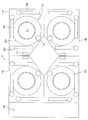
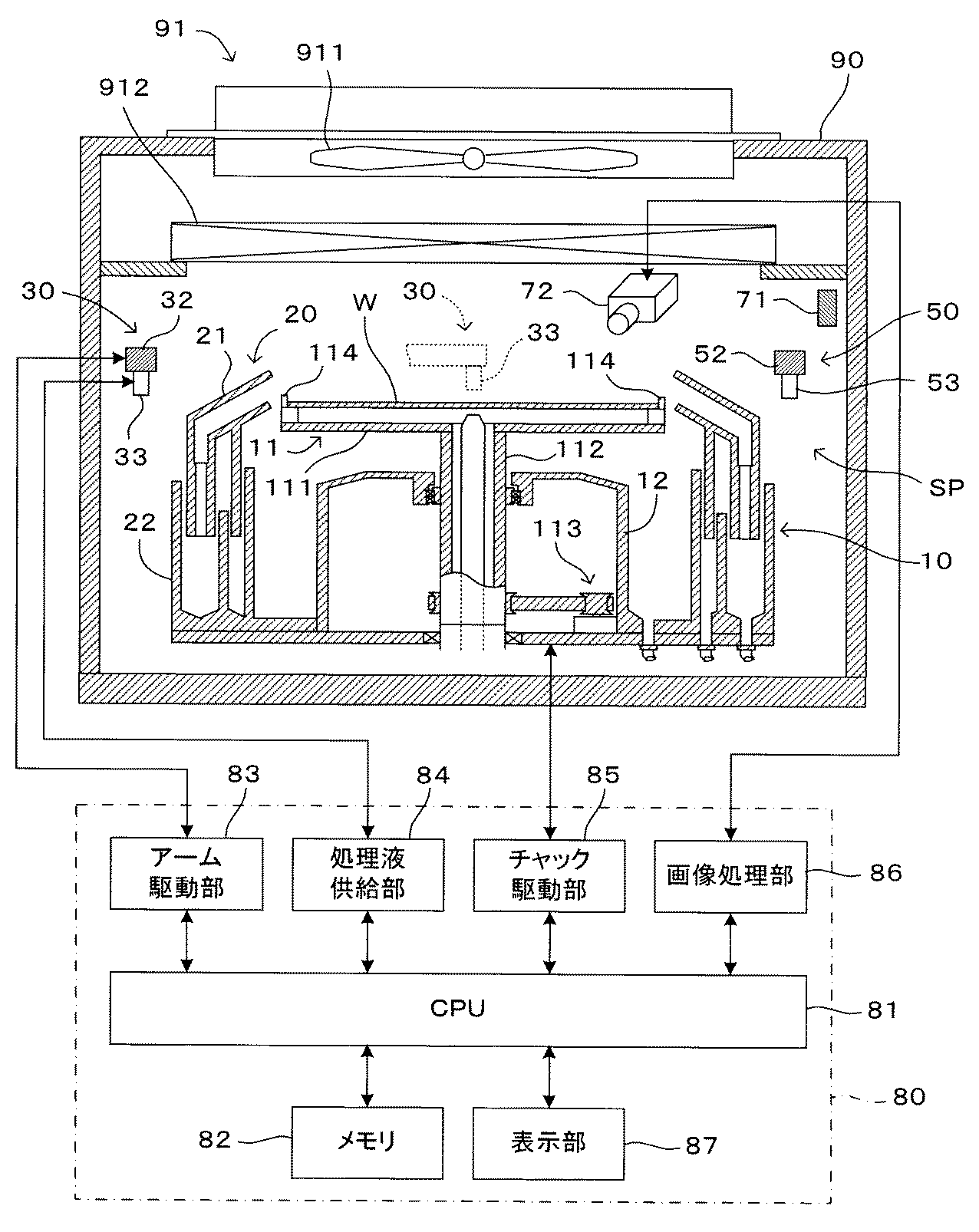
図2は一の基板処理ユニットの構造を示す上面図である。また、図3は図2のA−A矢視断面および基板処理ユニットの制御部の構成を示す図である。基板処理ユニット1Aは、半導体ウエハ等の円盤状の基板Wに対して処理液による洗浄やエッチング処理などの湿式処理を施すための枚葉式の湿式処理ユニットである。この基板処理ユニット1Aでは、チャンバー90の天井部分にファンフィルタユニット(FFU)91が配設されている。このファンフィルタユニット91は、ファン911およびフィルタ912を有している。したがって、ファン911の作動により取り込まれた外部雰囲気がフィルタ912を介してチャンバー90内の処理空間SPに供給される。基板処理システム1はクリーンルーム内に設置された状態で使用され、処理空間SPには常時クリーンエアが送り込まれる。
FIG. 2 is a top view showing the structure of one substrate processing unit. 3 is a diagram showing a cross section taken along the line AA of FIG. 2 and the configuration of the control unit of the substrate processing unit. The substrate processing unit 1A is a single-wafer type wet processing unit for performing wet processing such as cleaning with a processing liquid and etching processing on a disk-shaped substrate W such as a semiconductor wafer. In the
チャンバー90の処理空間SPには基板保持部10が設けられている。この基板保持部10は、基板表面を上方に向けた状態で基板Wを略水平姿勢に保持して回転させるものである。この基板保持部10は、基板Wよりも若干大きな外径を有する円盤状のスピンベース111と、略鉛直方向に延びる回転支軸112とが一体的に結合されたスピンチャック11を有している。回転支軸112はモータを含むチャック回転機構113の回転軸に連結されており、制御部80のチャック駆動部85からの駆動によりスピンチャック11が回転軸(鉛直軸)回りに回転可能となっている。これら回転支軸112およびチャック回転機構113は、円筒状のケーシング12内に収容されている。また、回転支軸112の上端部には、スピンベース111が一体的にネジなどの締結部品によって連結され、スピンベース111は回転支軸112により略水平姿勢に支持されている。したがって、チャック回転機構113が作動することで、スピンベース111が鉛直軸回りに回転する。制御部80は、チャック駆動部85を介してチャック回転機構113を制御して、スピンベース111の回転速度を調整することが可能である。
A
スピンベース111の周縁部付近には、基板Wの周端部を把持するための複数個のチャックピン114が立設されている。チャックピン114は、円形の基板Wを確実に保持するために3つ以上設けてあればよく(この例では6つ)、スピンベース111の周縁部に沿って等角度間隔で配置されている。チャックピン114のそれぞれは、基板Wの外周端面を押圧する押圧状態と、基板Wの外周端面から離れる解放状態との間を切り替え可能に構成されている。
Near the periphery of the
スピンベース111に対して基板Wが受け渡しされる際には、複数のチャックピン114のそれぞれを解放状態とする一方、基板Wを回転させて所定の処理を行う際には、複数のチャックピン114のそれぞれを押圧状態とする。このように押圧状態とすることによって、チャックピン114は基板Wの周端部を把持してその基板Wをスピンベース111から所定間隔を隔てて略水平姿勢に保持することができる。これにより、基板Wはその表面を上方に向け、裏面を下方に向けた状態で支持される。なお、チャックピン114としては、公知の構成、例えば特開2013−206983号公報に記載されたものを用いることができる。また、基板を保持する機構としてはチャックピンに限らず、例えば基板裏面を吸引して基板Wを保持する真空チャックを用いてもよい。
When the substrate W is delivered to the
ケーシング12の周囲には、スピンチャック11に水平姿勢で保持されている基板Wの周囲を包囲するようにスプラッシュガード20がスピンチャック11の回転軸に沿って昇降自在に設けられている。このスプラッシュガード20は回転軸に対して略回転対称な形状を有しており、それぞれスピンチャック11と同心円状に配置されて基板Wから飛散する処理液を受け止める複数段の(この例では2段の)ガード21と、ガード21から流下する処理液を受け止める液受け部22とを備えている。そして、制御部80に設けられた図示しないガード昇降機構がガード21を段階的に昇降させることで、回転する基板Wから飛散する薬液やリンス液などの処理液を分別して回収することが可能となっている。
A
スプラッシュガード20の周囲には、エッチング液等の薬液、リンス液、溶剤、純水、DIW(脱イオン水)など各種の処理液を基板Wに供給するための液供給部が少なくとも1つ設けられる。この例では、図2に示すように、3組の処理液吐出部30,40,50が設けられている。処理液吐出部30は、制御部80のアーム駆動部83により駆動されて鉛直軸周りに回動可能に構成された回動軸31と、該回動軸31から水平方向に延設されたアーム32と、アーム32の先端に下向きに取り付けられたノズル33とを備えている。アーム駆動部83により回動軸31が回動駆動されることで、アーム32が鉛直軸周りに揺動し、これによりノズル33は、図2において二点鎖線矢印で示すように、スプラッシュガード20よりも外側の退避位置(図3に実線で示す位置)と基板Wの回転中心の上方位置(図3に点線で示す位置)との間を往復移動する。ノズル33は、基板Wの上方に位置決めされた状態で、制御部80の処理液供給部84から供給される所定の処理液を吐出し、基板Wに処理液を供給する。
Around the
同様に、処理液吐出部40は、アーム駆動部83により回動駆動される回動軸41と、これに連結されたアーム42と、アーム42の先端に設けられて処理液供給部84から供給される処理液を吐出するノズル43とを備えている。また、処理液吐出部50は、アーム駆動部83により回動駆動される回動軸51と、これに連結されたアーム52と、アーム52の先端に設けられて処理液供給部84から供給される処理液を吐出するノズル53とを備えている。なお、処理液吐出部の数はこれに限定されず、必要に応じて増減されてもよい。
Similarly, the processing
スピンチャック11の回転により基板Wが所定の回転速度で回転した状態で、これらの処理液吐出部30,40,50がノズル33,43,53を順次基板Wの上方に位置させて処理液を基板Wに供給することにより、基板Wの洗浄処理が実行される。処理の目的に応じて、各ノズル33,43,53からは互いに異なる処理液が吐出されてもよく、同じ処理液が吐出されてもよい。また、1つのノズルから2種類以上の処理液が吐出されてもよい。基板Wの回転中心付近に供給された処理液は、基板Wの回転に伴う遠心力により外側へ広がり、最終的には基板Wの周端部から側方へ振り切られる。基板Wから飛散した処理液はスプラッシュガード20のガード21によって受け止められて液受け部22により回収される。
In a state where the substrate W is rotated at a predetermined rotation speed by the rotation of the
さらに、チャンバー90の処理空間SP内には、処理空間SP内を照明する照明部71と、スピンチャック11により保持された基板Wの表面を撮像するカメラ72とが設けられている。照明部71は例えばLEDランプを光源とするものであり、カメラ72による撮像を可能とするために必要な照明光を処理空間SP内に供給する。カメラ72は処理空間SP内で基板Wよりも上方に基板Wに向けて配置され、スピンチャック11により保持された基板Wの表面全体をその視野に包含する。
Further, in the processing space SP of the
図2に示すように、カメラ72は、平面視において照明部71から基板Wを見込む範囲に含まれる領域(破線L1、L2に挟まれた領域)の外側に設けられている。このため、照明部71から基板Wに直接入射した光の正反射光がカメラ72に入射することは回避されている。つまり、照明光の基板W表面での正反射光の進路を避けた位置にカメラ72が設けられている。これに対し、例えば図2に点線で示すようにカメラ72が破線L1、L2に挟まれた領域内に設けられている場合には、基板Wからの正反射光がカメラ72に入射することになる。
As shown in FIG. 2, the
詳しくは後述するが、この基板処理システム1では、カメラ72により基板Wの表面を撮像した画像を用いて基板Wの保持状態を判定するが、このとき、基板Wからの正反射光を含まない画像を用いて判定を行う。従来技術のように正反射光成分を用いて判定を行う技術では光源とカメラとの光軸ずれが判定精度に影響を与えるが、この基板処理システム1では、正反射光を含まない複数の画像の相対比較によって判定を行うので、このような光軸ずれの問題が生じない。この場合、正反射光成分はむしろ外乱となり得るので、基板W表面での正反射光がカメラ72に入射しないように、照明部71とカメラ72との位置が定められている。
Although details will be described later, in this
カメラ72により取得された画像データは制御部80の画像処理部86に与えられる。画像処理部86は、画像データに対し所定の画像処理を施して、基板Wの保持状態を判定するために必要な情報を取得する。
The image data acquired by the
上記の他、この基板処理システム1の制御部80には、予め定められた処理プログラムを実行して各部の動作を制御するCPU81と、CPU81により実行される処理プログラムや処理中に生成されるデータ等を記憶保存するためのメモリ82と、処理の進行状況や異常の発生などを必要に応じてユーザに報知するための表示部87とを備えている。なお、制御部80は各基板処理ユニット1A〜1Dごとに個別に設けられてもよく、また基板処理システム1に1組だけ設けられて各基板処理ユニット1A〜1Dを統括的に制御するように構成されてもよい。また、CPU81が画像処理部としての機能を兼ね備えていてもよい。
In addition to the above, the
次に、以上のように構成された基板処理ユニット1Aの動作について説明する。なお、説明を省略するが、他の基板処理ユニット1B〜1Dも同じように動作する。基板処理ユニット1Aは、インデクサ部1Eを介して外部から搬入される基板Wを受け入れて、基板Wを回転させながら各種の処理液を供給して湿式処理を実行する。湿式処理としては各種の処理液を用いた多くの公知技術があり、それらの任意のものを適用可能であるので、湿式処理の内容については説明を省略する。
Next, the operation of the substrate processing unit 1A configured as described above will be described. In addition, although description is abbreviate | omitted, other board | substrate processing units 1B-1D operate | move similarly. The substrate processing unit 1A receives a substrate W carried in from the outside via the
この基板処理ユニット1Aにおける動作上の特徴は、基板Wがスピンチャック11に載置されて回転され、所定の回転速度で湿式処理に供されるまでの間に、スピンチャック11による基板Wの保持状態が判定される点にある。すなわち、基板Wの回転が開始されてから処理速度に達するまでの間に、カメラ72により撮像される画像を用いて基板Wの保持状態が判定され、正常な保持状態であると判定されれば予定された湿式処理を実行する一方で、保持状態が異常であると判定されたときには直ちに基板Wの回転が停止される。以下、その処理内容について説明する。
The operational feature of the substrate processing unit 1A is that the substrate W is held by the
図4は基板処理ユニットの動作を示すフローチャートである。この動作は、CPU81が予め定められた処理プログラムを実行することにより実現される。基板Wが基板処理ユニット1Aに搬入されると、スピンチャック11、より具体的にはスピンベース111の周縁部に設けられた複数のチャックピン114に載置される(ステップS101)。基板Wが搬入される際にはスピンベース111に設けられたチャックピン114は解放状態となっており、基板Wが載置された後、チャックピン114が押圧状態に切り替わって基板Wがチャックピン114により保持される(ステップS102)。
FIG. 4 is a flowchart showing the operation of the substrate processing unit. This operation is realized by the
このとき、例えば基板Wの載置位置が不適切であった等の理由で、チャックピン114による基板Wの保持が不完全となることがあり得る。例えば基板Wがいずれかのチャックピン114に乗り上げた状態で載置され、これにより基板Wが水平姿勢から傾いた状態で保持されることがある。また例えば、チャックピン114が薬液による腐食で形状が次第に変化し、これにより基板Wを保持することができなくなったり、基板Wが偏心した状態で保持されてしまったりすることがある。
At this time, the holding of the substrate W by the chuck pins 114 may be incomplete, for example, because the mounting position of the substrate W is inappropriate. For example, the substrate W may be placed in a state where it rides on one of the chuck pins 114, and thus the substrate W may be held in a state of being inclined from a horizontal posture. Further, for example, the shape of the
このような状態で基板Wが回転されると、基板Wがスピンチャック11から脱落して破損したり、チャンバー90内の構成部品に衝突して装置が損傷するおそれがある。また、脱落には至らなくても、傾いたり偏心した状態で基板Wが回転することで、装置に異常振動が発生するおそれがある。このような問題を未然に防止するために、この基板処理ユニット1Aでは、カメラ72により撮像される画像を用いて基板Wの挙動を観察することで、スピンチャック11による基板Wの保持状態を判定する。
If the substrate W is rotated in such a state, the substrate W may drop from the
具体的には、チャック駆動部85を作動させてスピンチャック11を低速で回転させながら(ステップS103)、カメラ72により基板Wを連続的に撮像する(ステップS104)。これにより、基板Wの回転位相角が互いに異なる複数の画像が取得される。そして、画像処理部86が、得られた各画像から所定の特徴量を算出する(ステップS105)。ここでいう「特徴量」とは、撮像された画像から数値として定量的に算出可能な量であって、基板Wが正常に保持されているときと、不適切な保持状態にあるときとで異なる値を取り得るものである。
Specifically, the substrate W is continuously imaged by the
より具体的には、基板Wが正常に保持されているときには回転位相角が互いに異なる複数の画像間で変動が少ない一方、不適切な保持状態にあるときには複数の画像間で変動が大きくなるような量が、「特徴量」として好適なものである。特に、照明光の基板W表面での正反射光成分に依存しない特徴量が好ましい。このような特徴量としては各種のものが考えられるが、その具体例については後に説明する。 More specifically, when the substrate W is normally held, there is little fluctuation between a plurality of images having different rotation phase angles, while when the substrate W is in an inappropriate holding state, the fluctuation between the plurality of images is increased. This amount is suitable as the “feature amount”. In particular, a feature amount that does not depend on a specularly reflected light component on the surface of the substrate W of illumination light is preferable. Various features can be considered as such feature amounts, and specific examples thereof will be described later.
各画像での特徴量が求められると、回転位相角が互いに異なる複数の画像間における特徴量の変動量が予め定められた許容範囲内にあるかがCPU81により判定される(ステップS106)。前記したように、基板Wの保持状態が適切であれば変動が少なくなるような特徴量が選ばれていることから、特徴量の変動量が許容範囲内にあれば(ステップS106において「YES」)基板Wの保持状態は正常であると判定することができる。そこで、この場合には基板Wの回転速度を湿式処理用の規定値まで増加させ(ステップS107)、続いて予め定められた湿式処理を実行する(ステップS108)。湿式処理の内容については説明を省略する。
When the feature amount in each image is obtained, the
一方、回転位相角の変化に伴う特徴量の変動量が許容範囲を超えている場合には(ステップS106において「NO」)、基板Wの保持状態が異常であると判定することができる。そこで、直ちにスピンチャック11の回転駆動を中止して基板Wの回転を停止させ、スピンチャック11による基板Wの保持において異常がある旨を示すメッセージを表示部87に表示してユーザに報知する(ステップS111)。メッセージの表示に代えて、あるいはこれに加えて、例えば警告音による異常報知を行ってもよい。
On the other hand, when the variation amount of the feature amount accompanying the change in the rotation phase angle exceeds the allowable range (“NO” in step S106), it can be determined that the holding state of the substrate W is abnormal. Accordingly, the rotation drive of the
このように、基板Wを低速で回転させながらカメラ72による撮像を行い、基板Wの回転位相角が互いに異なる複数の画像間における特徴量の相対的な変動量によって保持状態を判定することで、不適切な保持状態のまま基板Wが高速回転されて基板Wや装置が損傷することが回避される。前述したように、撮像結果に基づく保持状態の判定には、照明光の基板W表面での正反射光成分に依存しない特徴量が用いられる。以下ではその3つの具体例について説明する。
In this way, by taking an image with the
<第1の例>
図5および図6は第1の例における判定原理を説明する図である。撮像結果に基づく保持状態の判定の第1の例では、スピンチャック11上での基板Wの傾きにより生じる基板W表面における輝度の変化に基づき保持状態の判定を行う。すなわち、この例における特徴量は、基板W表面の輝度である。
<First example>
5 and 6 are diagrams for explaining the determination principle in the first example. In the first example of determining the holding state based on the imaging result, the holding state is determined based on a change in luminance on the surface of the substrate W caused by the inclination of the substrate W on the
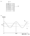
図5(a)左側に示すように、基板Wがスピンチャック11に適正に、すなわち基板W表面が略水平となるように保持された状態では、基板W表面の法線ベクトルNが鉛直上向きとなっており、これは基板Wの回転位相角によらず不変である。基板W表面は照明部71により照明されているが、基板W表面での正反射光はカメラ72に入射せず、照明光がチャンバー90内で散乱されて間接的に基板W表面に入射する光の反射光が主としてカメラ72により受光される。図5(a)右側には、カメラ72により撮像される基板W表面の様子が模式的に示されている。照明光の変化がなくカメラ72から見込む基板Wの傾きも基板Wの回転位相角によらず一定であることから、撮像される基板W表面の像の輝度も、基板Wの回転位相角によらず略一定であると予想される。
As shown on the left side of FIG. 5A, in a state where the substrate W is properly held by the
一方、図5(b)ないし図5(d)それぞれの左側に示すように、基板Wが例えば一部のチャックピン114に乗り上げて傾いた状態で保持されている場合を考えると、カメラ72から見込む基板Wの傾きが回転位相角により変化し、これに伴って、各図右側に示すように、撮像された基板W表面の輝度が基板Wの回転位相角に応じて変動する。
On the other hand, as shown on the left side of each of FIGS. 5B to 5D, when considering the case where the substrate W is held in a state of being tilted on a part of the chuck pins 114, for example, from the
照明光がチャンバー90内で十分に散乱されて特定の方向性を持たない場合、例えば図5(b)に示すように基板W表面の法線ベクトルVnがカメラ72と反対方向に向く成分を有しているとき、基板W表面からカメラ72に入射する光の量が少なくなり基板W表面の輝度が低くなると考えられる。このときの基板Wの回転位相角φを0度とすると、回転位相角φが180度である図5(d)の状態では、基板W表面の法線ベクトルVnがカメラ72の方向に向く成分を有し、基板Wからカメラ72に入射する光の量がより多くなり、撮像された画像における基板Wの輝度はより高くなる。これらの中間、すなわち図5(c)に示す回転位相角φが90度の状態では、基板W表面の輝度もこれらの中間的な値となると考えられる。
When the illumination light is sufficiently scattered in the
これらのことから、カメラ72により撮像される画像のうち基板W表面に対応する少なくとも一部の領域、例えば図5(a)に示すように基板Wの中心付近の領域R1の輝度を、基板Wの回転位相角が互いに異なる複数の画像間で比較することにより、基板Wの傾きの有無を判定することが可能である。具体的には次のようにすることができる。
Therefore, the brightness of at least a part of the image captured by the
図6(a)に示すように、カメラ72により撮像される画像のうち基板W表面に対応する一部領域R1について、当該領域R1に含まれる画素の各々を符号P(i,j)により表すこととする。ここで、パラメータi、jは領域R1における画素の座標位置を表す。領域R1の幅をM画素、高さをN画素とすると、領域R1の左上隅(もしくは左下隅)の画素の座標を(0,0)、これと対角の位置にある右下隅(もしくは右上隅)の画素の座標を(M−1,N−1)により表すことができる。当該領域R1に含まれる各画素P(i,j)の輝度値(画素値)を符号I(i,j)により表したとき、当該領域R1の輝度値Irを次式により定義する。
基板Wの回転位相角φを異ならせて撮像した複数の画像の各々について領域R1の輝度値Irを求め、これを回転位相角φに対してプロットすると、例えば図6(b)に示すように、輝度値Irは基板Wの1回転分(すなわちφ=360度)を最大周期として周期的に変化する。ここで、基板Wの表面が一様で、かつスピンチャック11に水平に保持された状態では、回転位相角φによらず輝度値Irは一定値になると考えられる。しかしながら、より一般的には、許容される基板Wの微小な傾きや位置ごとの基板Wの表面状態の差異に起因して周期的な変動が現れる。
When the luminance value Ir of the region R1 is obtained for each of a plurality of images picked up with different rotational phase angles φ of the substrate W and plotted against the rotational phase angle φ, for example, as shown in FIG. The luminance value Ir changes periodically with a maximum period of one rotation of the substrate W (that is, φ = 360 degrees). Here, in the state where the surface of the substrate W is uniform and is held horizontally by the
スピンチャック11による基板Wの保持状態が適正で基板Wが略水平姿勢に保持されていれば、図6(b)に曲線Aとして示すように、輝度値Irの変動量は比較的小さい。一方、図5(b)に示すように基板Wが傾いた状態で保持されているとき、図6(b)に曲線Bとして示すように、輝度値Irの周期的な変動がより大きくなる。このことから、例えば、輝度値Irの変動量について適宜の閾値Th1を予め設定しておき、撮像された複数の画像から求められる輝度値Irの変動量がこの閾値Th1以内であれば保持状態が正常、閾値Th1を超えている場合には基板Wの保持状態が異常であると判定することができる。
If the holding state of the substrate W by the
より具体的には、例えば、基板Wの少なくとも1回転分について複数の画像を撮像し、各画像中の領域Rについてそれぞれ求めた輝度値Irの最大値と最小値との差が閾値Th1よりも大きければ、基板Wの保持状態が異常であると判定することができる。また例えば、撮像の都度遅滞なく輝度値Irの算出を行うとともに算出済みの輝度値Irの最大値および最小値を記憶しておき、それらの差が閾値Th1を超えたことが判明した時点で保持状態が異常であると判定するようにしてもよい。いずれによっても、保持状態が判定されるまでの基板Wの回転量を1回転以内とすることができる。 More specifically, for example, a plurality of images are captured for at least one rotation of the substrate W, and the difference between the maximum value and the minimum value of the luminance value Ir obtained for each region R in each image is greater than the threshold Th1. If it is larger, it can be determined that the holding state of the substrate W is abnormal. Further, for example, the luminance value Ir is calculated without delay each time an image is taken, and the maximum value and the minimum value of the calculated luminance value Ir are stored, and stored when it is determined that the difference between them exceeds the threshold Th1. It may be determined that the state is abnormal. In any case, the rotation amount of the substrate W until the holding state is determined can be within one rotation.
閾値Th1については、許容される基板Wの傾き量、基板Wの表面状態や処理空間SP内の明るさ等に応じて予め実験的に定めておくことが可能である。また、領域R1の位置および面積を複数の画像間で同一としておき、輝度値Irの変動量の大きさによって保持状態を判定するので、領域R1に含まれる画素の画素値の単なる合計値を当該領域R1の輝度値Irとして用いることが可能である。すなわち、この例では、基板W表面の輝度を表す数値の基板Wの回転に伴う相対的な変化量が求められれば判定が可能であり、輝度を表す尺度は何であってもよい。 The threshold Th1 can be experimentally determined in advance according to the allowable tilt amount of the substrate W, the surface state of the substrate W, the brightness in the processing space SP, and the like. In addition, since the position and area of the region R1 are made the same among a plurality of images and the holding state is determined based on the amount of variation in the luminance value Ir, the mere total value of the pixel values of the pixels included in the region R1 is It can be used as the luminance value Ir of the region R1. That is, in this example, the determination can be made if the relative change amount accompanying the rotation of the substrate W of the numerical value indicating the luminance of the surface of the substrate W can be obtained, and any scale indicating the luminance can be used.
また、正反射光や透過光等をカメラ72に入射させる必要がないので、光軸調整を要せず、また照明光源として収束光ビームを出射するものを用いる必要もない。また、絶対的な輝度値ではなくその相対的な変化量により判定を行うため、基板Wが回転する間、照明条件が変わらなければ足り、光源の明るさを厳密に調整する必要もない。このように、この例では、細かい調整作業を必要とせず、簡単な構成で確実に基板の保持状態を判定することが可能である。
Further, since it is not necessary to cause the specularly reflected light or transmitted light to enter the
なお、上記の例では、基板Wの回転位相角φを異ならせた複数の画像のそれぞれについて、当該画像中の領域R1に含まれる画素の画素値の総計を輝度値Irとして求めた上で、複数の画像間で輝度値Irの比較を行っている。しかしながら、演算の順序を入れ替え、2つの画像間で互いに対応する画素間で画素値の差分を求め、その値を領域R1全体について合計しても技術的には等価であり、上記と同じ結果が得られる。 In the above example, for each of a plurality of images having different rotation phase angles φ of the substrate W, the total pixel value of the pixels included in the region R1 in the image is obtained as the luminance value Ir. The luminance value Ir is compared between a plurality of images. However, it is technically equivalent even if the order of operations is changed and the difference between the pixel values corresponding to each other between the two images is obtained and the values are summed for the entire region R1, and the same result as above is obtained. can get.
<第2の例>
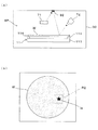
図7および図8は第2の例における判定原理を説明する図である。この例は、基板Wの表面が鏡面に近い高い反射率を有している場合に特に有効である。このような場合、チャンバー90内で保持された基板Wの表面には、照明部71からの光で照明された処理空間SP内で基板Wの表面に臨む位置に設けられた構造物の像が映り込む。例えば図7(a)に示すように、処理空間SPの上部隔壁に該当するチャンバー90の天井部分に形状既知の構造物92を設けておけば、基板W表面に映り込んだ構造物92の像がカメラ72により撮像される。
<Second example>
7 and 8 are diagrams for explaining the determination principle in the second example. This example is particularly effective when the surface of the substrate W has a high reflectance close to a mirror surface. In such a case, an image of a structure provided at a position facing the surface of the substrate W in the processing space SP illuminated by the light from the
構造物92の形状を例えば星型とした場合、撮像された画像には、図7(b)に示すように、基板W表面のうち構造物92に臨む位置に構造物92の形状に対応する形状の像Iaが現れる。画像のうち構造物92の像Iaが映り込む位置を含む領域R2に着目したとき、基板Wが水平姿勢に保持されていれば、基板Wの回転位相角によらず、領域R2における構造物92の像Iaの位置はほぼ変わらないと考えられる。
When the shape of the
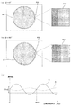
一方、図8(a)ないし図8(c)に示すように、基板Wが水平姿勢から傾いた状態でスピンチャック11に保持されていれば、カメラ72から見た基板W表面の傾き量が回転位相角に応じて変化することにより、領域R2における像Iaの位置が周期的に変動する。各図右側において点線で示される星型Ibは、基板Wの傾きがないと仮定したときの像Iaの位置を表している。
On the other hand, as shown in FIGS. 8A to 8C, if the substrate W is held by the
したがって、図8(d)に示すように、領域R2における像Iaの位置を指標する適宜の量(ここでは「位置指標量」という)を基板Wの回転位相角φに対してプロットしたとき、基板Wの傾きが許容範囲内であれば曲線Aとして示すように値の変動は小さい一方、基板Wが傾いていれば、曲線Bとして示すようにより大きな周期的変動が現れることになる。このことから、位置指標量の変動量、つまり基板Wの回転に伴う像Iaの相対的な位置ずれ量に対して所定の閾値Th2を予め設定しておき、基板Wの回転に伴う位置指標量の変動量が閾値Th2以内であれば基板Wの保持状態が正常であり、閾値Th2を超える場合には保持状態が異常であると判定することができる。すなわち、この例における位置指標量が、前述した「特徴量」に該当する。 Therefore, as shown in FIG. 8D, when an appropriate amount (herein referred to as “position index amount”) indicating the position of the image Ia in the region R2 is plotted against the rotational phase angle φ of the substrate W, If the inclination of the substrate W is within the allowable range, the fluctuation of the value is small as shown by the curve A. On the other hand, if the substrate W is inclined, a larger periodic fluctuation appears as shown by the curve B. Therefore, a predetermined threshold value Th2 is set in advance for the amount of fluctuation of the position index amount, that is, the relative displacement amount of the image Ia accompanying the rotation of the substrate W, and the position index amount associated with the rotation of the substrate W. If the fluctuation amount is within the threshold value Th2, the holding state of the substrate W is normal, and if it exceeds the threshold value Th2, it can be determined that the holding state is abnormal. That is, the position index amount in this example corresponds to the “feature amount” described above.
位置指標量について説明する。最も単純には、構造物92の像Iaから特定することが可能な代表点(例えば像の重心)の位置により、像Iaの位置を指標することが可能である。したがって、例えば基板Wを回転させながら撮像した複数の画像間における代表点の位置の差(すなわち距離)をもって位置指標量とすることが可能である。また例えば、所定の基準点(例えば基板Wの傾きがないと仮定したときの構造物92の像Ibの重心)と、各画像における代表点との距離をもって位置指標量としてもよい。
The position index amount will be described. Most simply, the position of the image Ia can be indicated by the position of a representative point (for example, the center of gravity of the image) that can be identified from the image Ia of the
ただしこの場合、例えば基板Wの回転に伴う代表点の軌跡が基準点を中心とする円となる場合のように、スカラー量である基準点からの距離のみで表現された位置指標量から基板Wの傾きを把握することが困難となる場合があり得る。また、図8等では基板Wの傾きおよび像の位置ずれを強調して示しているが、実際の装置における基板Wの傾きはごく小さく、像Iaの位置変動も僅かである。したがって、このような像の位置のみによる判定では十分な判定精度が得られない場合がある。 However, in this case, for example, when the trajectory of the representative point associated with the rotation of the substrate W is a circle centered on the reference point, the substrate W is calculated from the position index amount expressed only by the distance from the reference point, which is a scalar amount. It may be difficult to grasp the inclination of the. Further, in FIG. 8 and the like, the tilt of the substrate W and the image positional deviation are emphasized, but the tilt of the substrate W in an actual apparatus is very small, and the position fluctuation of the image Ia is slight. Therefore, sufficient determination accuracy may not be obtained by such determination based only on the position of the image.
より確度の高い方法として、基板Wの傾きがないと仮定したときの構造物92の像Ibをテンプレートとして、このテンプレートと実際に撮像された構造物92の像Iaとの重なりの程度をパターンマッチング処理によって定量化し、その値を位置指標量として用いることが考えられる。具体的には、パターンマッチングにより求められるマッチング座標、またはマッチングスコアを位置指標量とすることができる。
As a more accurate method, using the image Ib of the
基板Wが傾くことなくスピンチャック11に保持されている場合、構造物92の像Iaは基板Wの回転位相角φによらずほぼ基準像Ibと重なって観察される。すなわちマッチングスコアおよびマッチング座標の基板Wの回転位相角φによる変動が少ない。一方、基板Wが傾いた状態で保持されているとき、マッチングスコアおよびマッチング座標が基板Wの回転位相角φによって大きく変化する。これらの数値の変動量に対して適宜の閾値Th2を設定することで、基板Wの保持状態を的確に判定することができる。
When the substrate W is held on the
パターンマッチング処理としては種々の技術を適用することが可能である。ここではいくつかの例を挙げるが、各技術は公知であるので原理の説明は省略する。以下では、テンプレートにおける各画素P(i,j)の輝度値をT(i,j)、撮像された各画像の領域R2における各画素P(i,j)の輝度値をI(i,j)とする。パラメータi、jの定義は第1の例と同じである。 Various techniques can be applied as the pattern matching process. Here, some examples will be given, but the explanation of the principle is omitted because each technique is known. Hereinafter, the luminance value of each pixel P (i, j) in the template is T (i, j), and the luminance value of each pixel P (i, j) in the region R2 of each captured image is I (i, j). ). The definitions of parameters i and j are the same as in the first example.
(1)正規化相互相関(Normalized Cross Correlation;NCC)を用いる場合
以下の数式により、各画像における領域R2のテンプレートとの類似度を表すことができる。左辺の類似度RNCCが1に近いほど、2つの画像の類似度が高い、つまり撮像された画像における構造物92の像Ibの位置がテンプレートにおける像Iaの位置に近いことを表す。この場合、左辺の値RNCCがマッチングスコアに相当する。
(2)SSD(Sum of Squared Difference)を用いる場合
以下の数式により、各画像における領域R2のテンプレートとの類似度を表すことができる。左辺の値RSSDの値が小さいほど、2つの画像の類似度が高いことを表す。この場合、左辺の値RSSDがマッチングスコアに相当する。
(3)SAD(Sum of absolute Difference)を用いる場合
以下の数式により、各画像における領域R2のテンプレートとの類似度を表すことができる。この場合も、左辺の値RSADの値が小さいほど、2つの画像の類似度が高いことを表す。この場合、左辺の値RSADがマッチングスコアに相当する。
なお、パターンマッチングの方法はこれらに限定されず、知られている種々の技術を適用することが可能である。また、上記ではマッチング座標、マッチングスコアのいずれかを使ってその変動量から基板Wの保持状態の判定を行うこととしているが、これらを併用してもよい。すなわち、パターンマッチング処理により求められたマッチング座標、マッチングスコアの両方が所定の閾値を超えたときに異常と判定するようにしたり、これらの少なくとも一方が閾値を超えたときに異常と判定するようにすることが考えられる。 Note that the pattern matching method is not limited to these, and various known techniques can be applied. In the above description, either the matching coordinates or the matching score is used to determine the holding state of the substrate W from the amount of change, but these may be used together. That is, when both the matching coordinates obtained by the pattern matching process and the matching score exceed a predetermined threshold, it is determined as abnormal, or when at least one of these exceeds a threshold, it is determined as abnormal. It is possible to do.
<第3の例>
上記した2つの例は、主として基板Wの傾きを検出するのに適した態様である。一方、次に説明する第3の例は、上記例と同様に基板Wの傾きに対応するほか、特に円形の基板Wが偏心した、つまり基板Wの幾何学的な中心と回転中心とがずれた状態でスピンチャック11に保持された状態を検出するのに好適なものである。
<Third example>
The two examples described above are modes suitable mainly for detecting the tilt of the substrate W. On the other hand, the third example described below corresponds to the inclination of the substrate W as in the above example, and in particular, the circular substrate W is eccentric, that is, the geometric center and the rotation center of the substrate W are shifted. It is suitable for detecting the state held by the
図9は第3の例における判定原理を説明する図である。この例では、カメラ72により撮像される画像のうち基板Wの周端部の少なくとも一部を部分的に含む領域R3の画像内容に基づき基板Wの保持状態を判定する。基板Wが円形である場合、偏心のない状態、つまり基板Wの中心とスピンチャック11の回転中心とが一致した状態でスピンチャック11に保持されていれば、画像内において基板Wが占める領域は、基板Wの回転によって変動しない。
FIG. 9 is a diagram for explaining the determination principle in the third example. In this example, the holding state of the substrate W is determined based on the image content of the region R3 partially including at least a part of the peripheral end portion of the substrate W in the image captured by the
一方、基板Wが偏心した状態、つまり基板Wの中心とスピンチャック11の回転中心とにずれがある状態でスピンチャック11に保持されている場合、図9(a)および図9(b)左側にそれぞれ示すように、撮像された画像において基板Wが占める領域は、基板Wの回転位相角φに応じて変化する。図において点線は、偏心がない状態で基板Wが保持されているときに基板Wが占める領域を表している。
On the other hand, in the case where the substrate W is held on the
このため、図9(a)および図9(b)右側に拡大してそれぞれ示すように、画像のうち基板Wの周端部を含む一部領域R3では、当該領域R3における基板Wの周端部の位置が、基板Wの回転位相角により変化する。なお、基板Wの直径に対して領域R3が十分小さく選ばれていれば、領域R3において基板Wの周端部はほぼ直線とみなすことが可能である。 Therefore, as shown in enlarged views on the right side in FIGS. 9A and 9B, in the partial region R3 including the peripheral edge of the substrate W in the image, the peripheral edge of the substrate W in the region R3. The position of the part changes depending on the rotational phase angle of the substrate W. If the region R3 is selected to be sufficiently small with respect to the diameter of the substrate W, the peripheral end portion of the substrate W in the region R3 can be regarded as a substantially straight line.
したがって、当該領域R3に含まれる画素のうち基板Wに対応する画素(図において濃色で示す)の数が、基板Wの回転位相角φに応じて増減する。このような回転に伴う基板W周端部の位置の変化は、基板Wが水平姿勢であるがその幾何学的中心とスピンチャック11の回転中心とが一致しない状態で保持されているときに生じるほか、基板Wが傾いた状態でスピンチャック11に保持されているときにも、カメラ72から基板Wの周端部までの距離が周期的に変動することによっても生じる。
Therefore, the number of pixels (shown in dark color in the drawing) corresponding to the substrate W among the pixels included in the region R3 increases or decreases according to the rotation phase angle φ of the substrate W. Such a change in the position of the peripheral edge of the substrate W due to the rotation occurs when the substrate W is held in a horizontal posture but the geometric center thereof does not coincide with the rotation center of the
したがって、領域R3に含まれる画素のうち基板Wに対応するものの数を計数し、図9(c)に示すように、計数された画素数を基板Wの回転位相角φに対してプロットしたとき、画素数は基板Wの1回転分を周期として周期的に変動する。偏心が小さければ、図に曲線Aとして示すように画素数の変動も少ない一方、曲線Bとして示すように、偏心が大きい場合には画素数の変動量も大きくなる。そこで、画素数の変動量に対して適宜の閾値Th3を予め定めておき、種々の回転位相角φで撮像された各画像から求めた画素数の変動量が閾値Th3以内であれば基板Wの保持状態が正常であり、閾値Th3を超える場合には保持状態が異常であると判定することができる。すなわち、この例では、領域R3において基板Wに対応する画素の数が前述の「特徴量」に該当する。 Therefore, when the number of pixels corresponding to the substrate W among the pixels included in the region R3 is counted and the counted number of pixels is plotted against the rotation phase angle φ of the substrate W as shown in FIG. The number of pixels periodically varies with one rotation of the substrate W as a period. If the eccentricity is small, the variation in the number of pixels is small as shown by the curve A in the figure. On the other hand, as shown by the curve B, the variation in the number of pixels is large when the eccentricity is large. Therefore, an appropriate threshold value Th3 is determined in advance for the variation amount of the number of pixels, and if the variation amount of the pixel number obtained from each image captured at various rotational phase angles φ is within the threshold value Th3, the substrate W When the holding state is normal and exceeds the threshold Th3, it can be determined that the holding state is abnormal. That is, in this example, the number of pixels corresponding to the substrate W in the region R3 corresponds to the “feature amount” described above.
領域R3に含まれる画素が基板Wに対応したものであるかそれ以外の構造物に対応したものであるかについては、基板Wとそれ以外の構造物(具体的にはスピンベース111の上面)との間の光学的特性の差異およびカメラ72との距離の差異に起因する輝度の違いから判別することができる。また、基板Wの周囲に当接して設けられたチャックピン114や、基板Wの結晶方位を示す切り欠き(オリエンテーションフラットもしくはノッチ)が一時的に領域R3内に現れることがあり、これに起因して、領域R3のうち基板Wに対応する画素の数も変動することがある。しかしながら、偏心に起因する画素数の変動の周期が基板Wの回転周期に対応しているのに対して、これらの変動要因は基板Wの回転周期に対して極めて短い期間のみ現れるものであるから、適宜のフィルタリング処理によりその影響を排除することが可能である。
As to whether the pixel included in the region R3 corresponds to the substrate W or other structure, the substrate W and other structures (specifically, the upper surface of the spin base 111) And a difference in luminance caused by a difference in distance from the
基板Wの周端部を検出するのに際しては、上記以外に、例えば画像内でのエッジ抽出処理により基板Wとそれ以外の構造物との境界に対応する画素を特定する方法が考えられる。この場合、周端部の位置の最小分解能は画素サイズ程度となる。これに対し、上記方法では、基板Wの周方向にも広がりを有する領域R3内に含まれる基板Wに対応する画素の数を計数しているため、基板Wの径方向における1画素分の変位が画素の計数結果としては複数に拡大され、これにより基板W周端部の位置検出をより高い分解能で行うことが可能となる。その結果、誤判定に対するマージンを大きくすることができる。 In detecting the peripheral edge of the substrate W, in addition to the above, for example, a method of specifying a pixel corresponding to the boundary between the substrate W and the other structure by edge extraction processing in an image is conceivable. In this case, the minimum resolution at the position of the peripheral edge is about the pixel size. On the other hand, in the above method, since the number of pixels corresponding to the substrate W included in the region R3 that also extends in the circumferential direction of the substrate W is counted, the displacement of one pixel in the radial direction of the substrate W However, the result of counting pixels is expanded to a plurality, so that the position of the peripheral edge of the substrate W can be detected with higher resolution. As a result, a margin for erroneous determination can be increased.
<その他>
以上のように、上記実施形態では、スピンチャック11に保持された基板Wをカメラ72により撮像し、その撮像結果に基づいて基板Wの保持状態を判定している。その具体例として示した上記各例では、撮像された画像のうち一部領域の画像内容を、基板Wの回転位相角を互いに異ならせた複数の画像間で相対的に比較する。具体的には、第1の例においては、基板Wの一部領域R1における輝度の変動量に基づき基板Wの保持状態を判定する。また、第2の例においては、チャンバー90により囲まれた処理空間SP内の構造物92が基板W表面に映り込んでなる像Iaの位置変動量に基づき基板Wの保持状態を判定する。また、第3の例においては、基板Wの周端部を含む領域R3において基板Wが占める領域を画素の数を計数することにより求めて基板Wの保持状態を判定する。
<Others>
As described above, in the above embodiment, the
これらの例のいずれにおいても、複数の画像間における画像内容の相対的な比較により判定が行われ、また正反射光成分や透過光成分などの直接光成分を用いないので、光軸調整や光量調整など判定のための細かい調整を必要とせず、簡単にかつ確実に基板の保持状態を判定することが可能である。また、基板Wを回転させた状態での検出が可能であるため、判定のための特別な処理シーケンスを設けなくても、湿式処理を実行するために基板Wを回転させるプロセスの中で保持状態の判定を行うことが可能である。このため、湿式処理のためのタクトタイムの低下が生じない。また、不適切な保持状態である場合には直ちに回転を停止させることで、そのまま回転を継続した場合に生じうる基板や装置の破損を未然に防止することができ、これらの問題が発生することによる生産性の低下を防止することができる。 In any of these examples, the determination is made by relative comparison of image contents between a plurality of images, and since direct light components such as specular reflection light components and transmitted light components are not used, optical axis adjustment and light amount It is possible to easily and reliably determine the holding state of the substrate without requiring fine adjustment for determination such as adjustment. Further, since the detection in a state where the substrate W is rotated is possible, the holding state in the process of rotating the substrate W in order to perform the wet process without providing a special processing sequence for determination. It is possible to make a determination. For this reason, the tact time for wet processing does not decrease. In addition, by stopping rotation immediately when it is in an improper holding state, it is possible to prevent damage to the substrate and the device that may occur if rotation continues as it is, and these problems will occur It is possible to prevent the productivity from being lowered.
以上説明したように、上記実施形態では、基板処理システム1またはこれに設けられた各基板処理ユニット1A〜1Dが本発明の「基板処理装置」に該当している。各基板処理ユニット1A等においては、スピンチャック11が本発明の「保持手段」として機能しており、チャック回転機構113およびチャック駆動部85が一体として本発明の「回転手段」として機能している。また、処理空間SPが本発明の「処理空間」に相当し、チャンバー90が本発明の「処理室」として機能している。
As described above, in the above-described embodiment, the
また、上記実施形態では、照明部71が本発明の「照明手段」として機能する一方、カメラ72が本発明の「撮像手段」として機能している。また、画像処理部86およびCPU81が一体として、本発明の「判定手段」として機能している。
In the above embodiment, the
また撮像された画像の一部領域R1、R2、R3が本発明の「比較対象領域」に相当している。そして、各領域に対応して設けられた閾値Th1、Th2、Th3がそれぞれ本発明の「第1閾値」、「第2閾値」、「第3閾値」に相当する。さらに、第2の例においては、チャンバー90内に設けられた構造物92が本発明の「特定部位」および「位置基準マーク」として機能している。
Further, partial regions R1, R2, and R3 of the captured image correspond to the “comparison target region” of the present invention. The threshold values Th1, Th2, and Th3 provided corresponding to each region correspond to the “first threshold value”, “second threshold value”, and “third threshold value” of the present invention, respectively. Furthermore, in the second example, the
なお、本発明は上記した実施形態に限定されるものではなく、その趣旨を逸脱しない限りにおいて上述したもの以外に種々の変更を行うことが可能である。例えば、上記実施形態では、カメラ72がスピンチャック11に保持された基板Wの表面全体を撮像視野内に収めており、上記各例ではそのうちの一部領域を用いてスピンチャック11による基板Wの保持状態を判定している。しかしながら、単に上記したいずれかの例に則り基板の保持状態を判定するのみであれば、基板全体を撮像する必要はなく、判定のために必要な領域のみの撮像がなされれば足りる。ただし、上記のように基板W全体を撮像するように構成された場合には、次のような利点がある。第1に、同一の構成で上記した各例のいずれをも実行可能することが可能である。したがって、目的に応じて判定方法を切り替えたり、複数の判定方法を併用して保持状態の判定を行うことも可能となる。第2に、保持状態の判定とは異なる目的で画像を用いることができる。例えば、基板Wへの処理液の供給状態を観察することで処理液供給量の最適化を図ったり、基板Wの状態をリアルタイムに観察しながら処理の進行管理を行う等の目的に、カメラ72による画像を利用することができる。
The present invention is not limited to the above-described embodiment, and various modifications other than those described above can be made without departing from the spirit of the present invention. For example, in the above-described embodiment, the
また、上記実施形態では、処理室(処理空間SP)に照明光を導入する本発明の「照明手段」としての照明部71を設けているが、基板処理システム1が明るい室内に設置された状況では、チャンバー90の一部に導光窓を設けて外光を処理空間SP内に導入するだけでも、カメラ72による撮像を行うのに十分な照明光量が得られる場合もあり得る。このような場合、照明部を設けず(あるいは点灯させず)に導光窓から入射する外光を照明光として用いてもよい。この場合、導光窓が本発明の「照明手段」としての機能を有することになる。
Moreover, in the said embodiment, although the
また、上記実施形態では、照明部71およびカメラ72を処理空間SP内に設置しているが、例えばこれらの少なくとも一方をチャンバー90の外部に設置し、チャンバー90に設けられた透明窓を介して処理空間SP内を照明または撮像する構成であってもよい。このような構成では、照明手段や撮像手段に処理液が付着することが回避される。
Moreover, in the said embodiment, although the
また、上記実施形態では、照明部71から出射されて基板Wで正反射される光の進路を避けてカメラ72を設けているが、基板Wからの正反射光が一切カメラ72に入射しないようにすることは必須でない。すなわち、少なくとも判定に用いられる領域(比較対象領域)R1、R2、R3については当該領域からの正反射光がカメラ72に入射しないことが望ましいが、判定に用いられない他の領域に関しては、比較対象領域の画像内容に影響を及ぼさない限り、その領域からの正反射光がカメラ72に入射していても構わない。
In the above embodiment, the
また、上記実施形態は基板Wに対し湿式処理を行う基板処理システム1に本発明を適用したものであるが、基板に対して行われる処理はこのような湿式処理に限定されず任意である。すなわち、この発明は、基板を保持して回転させるための構成を有する各種の基板処理装置に対して適用可能である。また、処理対象となる基板は半導体基板に限定されず、例えばプリント配線基板やガラス基板等、種々のものを使用可能である。また、基板の形状も上記のような円形のものに限定されない。
Moreover, although the said embodiment applies this invention to the
この発明は、基板を水平姿勢に保持しながら回転させて所定の処理を行う各種の基板処理装置に対して適用することが可能である。 The present invention can be applied to various substrate processing apparatuses that perform predetermined processing by rotating a substrate while holding the substrate in a horizontal posture.
1 基板処理システム(基板処理装置)
1A〜1D 基板処理ユニット(基板処理装置)
11 スピンチャック(保持手段)
71 照明部(照明手段)
72 カメラ(撮像手段)
81 CPU(判定手段)
85 チャック駆動部(回転手段)
86 画像処理部(判定手段)
90 チャンバー(処理室)
92 構造物(特定部位、位置基準マーク)
111 スピンベース
113 チャック回転機構(回転手段)
114 チャックピン
R1、R2、R3 比較対象領域
SP 処理空間
Th1 第1閾値
Th2 第2閾値
Th3 第3閾値
W 基板
1 Substrate processing system (substrate processing equipment)
1A to 1D substrate processing unit (substrate processing apparatus)
11 Spin chuck (holding means)
71 Illumination part (illumination means)
72 Camera (imaging means)
81 CPU (determination means)
85 Chuck drive (rotating means)
86 Image processing unit (determination means)
90 chamber (processing room)
92 Structures (specific parts, position reference marks)
111
114 Chuck pins R1, R2, R3 Comparison target area SP Processing space Th1 First threshold Th2 Second threshold Th3 Third threshold W Substrate
Claims (16)
前記保持手段を略鉛直軸周りに回転させる回転手段と、
前記保持手段を収容する処理空間を形成する処理室と、
前記処理室内に照明光を導入する照明手段と、
前記保持手段に保持された前記基板を撮像する撮像手段と、
前記撮像手段により撮像された画像から、前記基板表面のうち前記照明手段の正反射像を含まない少なくとも一部を含む領域を比較対象領域として、前記基板の回転位相角を互いに異ならせて撮像した複数の画像間における前記比較対象領域の画像内容の比較結果に基づき、前記保持手段による前記基板の保持状態を判定する判定手段と
を備える基板処理装置。 Holding means for holding the substrate in a substantially horizontal position;
Rotating means for rotating the holding means about a substantially vertical axis;
A processing chamber for forming a processing space for accommodating the holding means;
Illumination means for introducing illumination light into the processing chamber;
Imaging means for imaging the substrate held by the holding means;
From the image captured by the imaging unit, an image including at least a part of the surface of the substrate that does not include the regular reflection image of the illumination unit is used as a comparison target region, and images are captured with different rotational phase angles of the substrate. A substrate processing apparatus comprising: a determination unit that determines a holding state of the substrate by the holding unit based on a comparison result of image contents of the comparison target region between a plurality of images.
前記判定手段は、撮像された前記基板表面のうち前記特定部位の像を含む領域を前記比較対象領域として、前記複数の画像間における前記特定部位の像の位置の比較結果に基づき前記保持状態を判定する請求項1に記載の基板処理装置。 The imaging means captures an image including an image of a specific part in the processing chamber reflected on the surface of the substrate;
The determination means sets the holding state based on a comparison result of the position of the image of the specific part between the plurality of images, with an area including the image of the specific part of the imaged substrate surface as the comparison target area. The substrate processing apparatus of Claim 1 which determines.
前記基板を照明手段により照明する工程と、
前記保持手段に保持された前記基板の画像を、前記基板の鉛直軸周りの回転位相角を互いに異ならせて複数撮像する工程と、
撮像された複数の前記画像の各々について、前記基板表面のうち照明光の正反射光成分を含まない少なくとも一部を含む領域を比較対象領域とし、前記複数の画像間における前記比較対象領域の画像内容の比較結果に基づき、前記保持手段による前記基板の保持状態を判定する工程と
を備える基板処理方法。 Holding the substrate in a holding means for holding the substrate in a substantially horizontal position in the processing chamber;
Illuminating the substrate with illumination means;
Imaging a plurality of images of the substrate held by the holding means with different rotational phase angles around the vertical axis of the substrate;
For each of the plurality of captured images, a region including at least a part of the substrate surface that does not include the specularly reflected light component of illumination light is set as a comparison target region, and the image of the comparison target region between the plurality of images. And a step of determining a holding state of the substrate by the holding unit based on a comparison result of contents.
撮像された前記基板表面のうち前記特定部位の像を含む領域を前記比較対象領域として、前記複数の画像間における前記特定部位の像の位置の比較結果に基づき前記保持状態を判定する請求項13に記載の基板処理方法。 Each of the plurality of images includes an image of a specific part in the processing chamber reflected on the surface of the substrate,
14. The holding state is determined based on a comparison result of the position of the image of the specific part between the plurality of images, with an area including the image of the specific part of the imaged substrate surface as the comparison target area. The substrate processing method as described in 2. above.
Priority Applications (1)
| Application Number | Priority Date | Filing Date | Title |
|---|---|---|---|
| JP2013236903A JP2015096830A (en) | 2013-11-15 | 2013-11-15 | Substrate processing apparatus and substrate processing method |
Applications Claiming Priority (1)
| Application Number | Priority Date | Filing Date | Title |
|---|---|---|---|
| JP2013236903A JP2015096830A (en) | 2013-11-15 | 2013-11-15 | Substrate processing apparatus and substrate processing method |
Publications (1)
| Publication Number | Publication Date |
|---|---|
| JP2015096830A true JP2015096830A (en) | 2015-05-21 |
Family
ID=53374190
Family Applications (1)
| Application Number | Title | Priority Date | Filing Date |
|---|---|---|---|
| JP2013236903A Pending JP2015096830A (en) | 2013-11-15 | 2013-11-15 | Substrate processing apparatus and substrate processing method |
Country Status (1)
| Country | Link |
|---|---|
| JP (1) | JP2015096830A (en) |
Cited By (8)
| Publication number | Priority date | Publication date | Assignee | Title |
|---|---|---|---|---|
| JP2017183498A (en) * | 2016-03-30 | 2017-10-05 | 東京エレクトロン株式会社 | Substrate processing apparatus and imaging method for substrate processing apparatus |
| US10402997B2 (en) | 2015-10-27 | 2019-09-03 | SCREEN Holdings Co., Ltd. | Displacement detecting apparatus, displacement detecting method and substrate processing apparatus |
| CN111009477A (en) * | 2018-10-05 | 2020-04-14 | 株式会社斯库林集团 | Substrate processing method and substrate processing apparatus |
| JP2020061417A (en) * | 2018-10-05 | 2020-04-16 | 東京エレクトロン株式会社 | Substrate processing apparatus and inspection method |
| JP2021141233A (en) * | 2020-03-06 | 2021-09-16 | 株式会社Screenホールディングス | Substrate processing equipment and substrate processing method |
| WO2021192738A1 (en) * | 2020-03-27 | 2021-09-30 | 株式会社Screenホールディングス | Substrate processing device and substrate processing method |
| WO2023127240A1 (en) * | 2021-12-27 | 2023-07-06 | 株式会社Screenホールディングス | Movement monitoring method and manufacturing apparatus |
| JPWO2023243438A1 (en) * | 2022-06-16 | 2023-12-21 |
Citations (5)
| Publication number | Priority date | Publication date | Assignee | Title |
|---|---|---|---|---|
| JP2000298862A (en) * | 1999-04-14 | 2000-10-24 | Pioneer Electronic Corp | Liquid crystal tilt servo apparatus |
| JP2000323555A (en) * | 1999-05-10 | 2000-11-24 | Nissin High Voltage Co Ltd | Method and apparatus for detecting abnormality in wafer loaded in adaptor for holding of semiconductor wafer |
| JP2007251143A (en) * | 2006-02-15 | 2007-09-27 | Olympus Corp | Visual inspection system |
| JP2011145171A (en) * | 2010-01-14 | 2011-07-28 | Nikon Corp | Shape detection device |
| JP2013110270A (en) * | 2011-11-21 | 2013-06-06 | Tokyo Electron Ltd | Substrate processing apparatus, substrate processing method, and computer readable storage medium storing substrate processing program |
-
2013
- 2013-11-15 JP JP2013236903A patent/JP2015096830A/en active Pending
Patent Citations (5)
| Publication number | Priority date | Publication date | Assignee | Title |
|---|---|---|---|---|
| JP2000298862A (en) * | 1999-04-14 | 2000-10-24 | Pioneer Electronic Corp | Liquid crystal tilt servo apparatus |
| JP2000323555A (en) * | 1999-05-10 | 2000-11-24 | Nissin High Voltage Co Ltd | Method and apparatus for detecting abnormality in wafer loaded in adaptor for holding of semiconductor wafer |
| JP2007251143A (en) * | 2006-02-15 | 2007-09-27 | Olympus Corp | Visual inspection system |
| JP2011145171A (en) * | 2010-01-14 | 2011-07-28 | Nikon Corp | Shape detection device |
| JP2013110270A (en) * | 2011-11-21 | 2013-06-06 | Tokyo Electron Ltd | Substrate processing apparatus, substrate processing method, and computer readable storage medium storing substrate processing program |
Cited By (19)
| Publication number | Priority date | Publication date | Assignee | Title |
|---|---|---|---|---|
| US10402997B2 (en) | 2015-10-27 | 2019-09-03 | SCREEN Holdings Co., Ltd. | Displacement detecting apparatus, displacement detecting method and substrate processing apparatus |
| JP2017183498A (en) * | 2016-03-30 | 2017-10-05 | 東京エレクトロン株式会社 | Substrate processing apparatus and imaging method for substrate processing apparatus |
| JP7090005B2 (en) | 2018-10-05 | 2022-06-23 | 東京エレクトロン株式会社 | Board processing equipment and inspection method |
| CN111009477A (en) * | 2018-10-05 | 2020-04-14 | 株式会社斯库林集团 | Substrate processing method and substrate processing apparatus |
| JP2020061417A (en) * | 2018-10-05 | 2020-04-16 | 東京エレクトロン株式会社 | Substrate processing apparatus and inspection method |
| JP2021141233A (en) * | 2020-03-06 | 2021-09-16 | 株式会社Screenホールディングス | Substrate processing equipment and substrate processing method |
| JP7486984B2 (en) | 2020-03-06 | 2024-05-20 | 株式会社Screenホールディングス | Substrate processing apparatus and substrate processing method |
| JP7426874B2 (en) | 2020-03-27 | 2024-02-02 | 株式会社Screenホールディングス | Substrate processing apparatus and substrate processing method |
| JP2021156741A (en) * | 2020-03-27 | 2021-10-07 | 株式会社Screenホールディングス | Substrate processing equipment and substrate processing method |
| WO2021192738A1 (en) * | 2020-03-27 | 2021-09-30 | 株式会社Screenホールディングス | Substrate processing device and substrate processing method |
| WO2023127240A1 (en) * | 2021-12-27 | 2023-07-06 | 株式会社Screenホールディングス | Movement monitoring method and manufacturing apparatus |
| JP2023096643A (en) * | 2021-12-27 | 2023-07-07 | 株式会社Screenホールディングス | MOTION MONITORING METHOD AND MANUFACTURING APPARATUS |
| KR20240107158A (en) * | 2021-12-27 | 2024-07-08 | 가부시키가이샤 스크린 홀딩스 | Motion monitoring method and manufacturing device |
| TWI855419B (en) * | 2021-12-27 | 2024-09-11 | 日商斯庫林集團股份有限公司 | Operation monitoring method and manufacturing apparatus |
| JP7734070B2 (en) | 2021-12-27 | 2025-09-04 | 株式会社Screenホールディングス | Operation monitoring method and manufacturing device |
| KR102925369B1 (en) * | 2021-12-27 | 2026-02-09 | 가부시키가이샤 스크린 홀딩스 | Motion monitoring method and manufacturing device |
| JPWO2023243438A1 (en) * | 2022-06-16 | 2023-12-21 | ||
| WO2023243438A1 (en) * | 2022-06-16 | 2023-12-21 | 東京エレクトロン株式会社 | Substrate treatment device and substrate treatment method |
| JP7778238B2 (en) | 2022-06-16 | 2025-12-01 | 東京エレクトロン株式会社 | Substrate processing apparatus and substrate processing method |
Similar Documents
| Publication | Publication Date | Title |
|---|---|---|
| TWI550748B (en) | Displacement detecting device, substrate processing device, displacement detecting method, and substrate processing method | |
| JP2015096830A (en) | Substrate processing apparatus and substrate processing method | |
| JP6352133B2 (en) | Position detection apparatus, substrate processing apparatus, position detection method, and substrate processing method | |
| US11908752B2 (en) | Substrate processing apparatus and substrate processing method | |
| JP6785092B2 (en) | Displacement detection device, displacement detection method and substrate processing device | |
| JP6541491B2 (en) | Falling determination method, falling determination device and discharge device | |
| JP6553487B2 (en) | Discharge determination method and discharge apparatus | |
| JP2016122681A (en) | Substrate processing apparatus and substrate processing method | |
| JP6362466B2 (en) | Substrate holding inspection method and substrate processing apparatus | |
| WO2018061338A1 (en) | Detecting method and detecting device | |
| JP2015173148A (en) | substrate processing apparatus and substrate processing method | |
| US10402997B2 (en) | Displacement detecting apparatus, displacement detecting method and substrate processing apparatus | |
| KR20210031513A (en) | Movable part position detection method, substrate processing method, substrate processing apparatus and substrate processing system | |
| WO2020071212A1 (en) | Substrate processing method and substrate processing device | |
| JP6511572B2 (en) | Substrate holding inspection method and substrate processing apparatus | |
| JP2023045854A (en) | Substrate processing device and substrate processing method | |
| JP2019168411A (en) | Position detector, substrate processing device, position detection method, and substrate processing method |
Legal Events
| Date | Code | Title | Description |
|---|---|---|---|
| A621 | Written request for application examination |
Free format text: JAPANESE INTERMEDIATE CODE: A621 Effective date: 20160608 |
|
| A977 | Report on retrieval |
Free format text: JAPANESE INTERMEDIATE CODE: A971007 Effective date: 20170316 |
|
| A131 | Notification of reasons for refusal |
Free format text: JAPANESE INTERMEDIATE CODE: A131 Effective date: 20170328 |
|
| A521 | Request for written amendment filed |
Free format text: JAPANESE INTERMEDIATE CODE: A523 Effective date: 20170526 |
|
| RD04 | Notification of resignation of power of attorney |
Free format text: JAPANESE INTERMEDIATE CODE: A7424 Effective date: 20170725 |
|
| A02 | Decision of refusal |
Free format text: JAPANESE INTERMEDIATE CODE: A02 Effective date: 20171107 |