JP2015102207A - Lock nut - Google Patents
Lock nut Download PDFInfo
- Publication number
- JP2015102207A JP2015102207A JP2013245103A JP2013245103A JP2015102207A JP 2015102207 A JP2015102207 A JP 2015102207A JP 2013245103 A JP2013245103 A JP 2013245103A JP 2013245103 A JP2013245103 A JP 2013245103A JP 2015102207 A JP2015102207 A JP 2015102207A
- Authority
- JP
- Japan
- Prior art keywords
- friction piece
- nut
- friction
- degrees
- thread
- Prior art date
- Legal status (The legal status is an assumption and is not a legal conclusion. Google has not performed a legal analysis and makes no representation as to the accuracy of the status listed.)
- Pending
Links
- 230000007704 transition Effects 0.000 claims abstract description 24
- 230000002265 prevention Effects 0.000 claims abstract description 22
- 230000004323 axial length Effects 0.000 claims description 15
- 230000015572 biosynthetic process Effects 0.000 description 9
- 230000002093 peripheral effect Effects 0.000 description 4
- 239000002184 metal Substances 0.000 description 3
- 238000004804 winding Methods 0.000 description 3
- 238000005452 bending Methods 0.000 description 2
- 230000008859 change Effects 0.000 description 2
- 238000013461 design Methods 0.000 description 2
- 230000000694 effects Effects 0.000 description 2
- 238000000034 method Methods 0.000 description 2
- 229910000639 Spring steel Inorganic materials 0.000 description 1
- 229910000831 Steel Inorganic materials 0.000 description 1
- 230000009471 action Effects 0.000 description 1
- 238000007796 conventional method Methods 0.000 description 1
- 230000007423 decrease Effects 0.000 description 1
- 230000007547 defect Effects 0.000 description 1
- 238000005553 drilling Methods 0.000 description 1
- 230000005489 elastic deformation Effects 0.000 description 1
- 230000006872 improvement Effects 0.000 description 1
- 238000004519 manufacturing process Methods 0.000 description 1
- 239000000463 material Substances 0.000 description 1
- 238000012986 modification Methods 0.000 description 1
- 230000004048 modification Effects 0.000 description 1
- 238000012545 processing Methods 0.000 description 1
- 239000011347 resin Substances 0.000 description 1
- 229920005989 resin Polymers 0.000 description 1
- 229910001220 stainless steel Inorganic materials 0.000 description 1
- 239000010935 stainless steel Substances 0.000 description 1
- 239000010959 steel Substances 0.000 description 1
- 238000003466 welding Methods 0.000 description 1
Images
Landscapes
- Bolts, Nuts, And Washers (AREA)
Abstract
Description
本発明は、緩み止めナットの改良に関するものである。 The present invention relates to an improvement of a locking nut.
従来より、樹脂やフリクションリング等のプリベリングトルク発生部をナットに取り付け、ボルトとの摩擦抵抗によって戻り止め作用を発揮させるプリベリングトルク型の緩み止めナットが、振動の多い箇所の締付手段として広く使用されている。
本発明の出願人並びにその関係者はプリベリングトルク型の緩み止めナットについて大きなシェアを有しており、これまでにも出願人並びにその関係者は特許文献1〜3に示すものの他、多数の出願を行なっている。特許文献1〜3にあっては、ナット本体の、座面に対向する端面にフリクションリングを装着したナットを開示する。このフリクションリングは、金属製のバネ弾性を有する環状体であり、環状体の内周から一体的に内方向に突設された弧状のフリクション片を有する。このフリクション片は、ボルトとの螺合に際して、その雄ねじに係合する。この雄ねじは、雄ねじの進行に伴い弾性変形し、これによってプリベリングトルクを発生させることによってナットの緩み止めをなすものである。特許文献1にあっては、約60度の範囲に渡るフリクション片が3個等間隔に形成されたもので、フリクション片間の移行部からボルトのねじ山が侵入するようにしたものが開示されている。特許文献2にあっては、約180度の範囲に渡って形成されたフリクション片を1個有するものであり、約180度の範囲に渡って前記移行部か形成されている。特許文献3にあっては、比較的緩やかなリード角を有するナットにおいて、1個のフリクション片が約280度の範囲に渡って形成され、約80度の範囲に渡って前記移行部か形成されている。
Conventionally, a pre-baling torque type locking nut that attaches a pre-ringing torque generating part such as resin or friction ring to the nut and exerts a detent action by frictional resistance with the bolt is used as a tightening means for places with a lot of vibration. Widely used.
The applicant of the present invention and the related parties have a large share of the pre-torque torque type locking nut. I am applying. In Patent Documents 1 to 3, a nut is disclosed in which a friction ring is mounted on an end surface of the nut body facing the seat surface. This friction ring is an annular body made of metal spring elasticity, and has an arc-shaped friction piece integrally projecting inward from the inner periphery of the annular body. The friction piece engages with the male screw when screwed with the bolt. This male screw is elastically deformed with the progress of the male screw, thereby generating pre-leveling torque, thereby preventing the nut from loosening. Patent Document 1 discloses a configuration in which three pieces of friction covering a range of about 60 degrees are formed at equal intervals, and a screw thread of a bolt enters from a transition portion between the pieces of friction. ing. In Patent Document 2, there is one friction piece formed over a range of about 180 degrees, and the transition portion is formed over a range of about 180 degrees. In
このように、フリクション片の設計にあっては、種々の態様が提案されているが、一般にフリクション片を周方向に長い範囲に渡って形成する方が、ボルトのねじ山に対するフリクション片の係合面積と弾性変形の度合いが大きくなり、フリクショントルクを大きくすることができる。 As described above, various aspects have been proposed for the design of the friction piece. Generally, it is more effective to form the friction piece over a long range in the circumferential direction. The area and the degree of elastic deformation increase, and the friction torque can be increased.
他方、この種の緩み止めナットにあっては、前記移行部からボルトのねじ山が円滑に侵入できるように、ナット本体のねじ山の切り上がり部分との位置関係を調製して、フリクションリングをナット端面に取り付ける必要がある。具体的には、フリクションリングをナット端面に接するように取り付ける場合には、ナット本体のねじ山の切り上がり部分が、移行部に位置するように取り付ける必要がある。この取付精度が低下すると、ボルトのねじ山がうまくフリクション片に係合することができず、ボルトのねじ山やフリクション片を破損したり、過大なねじ込みトルクが発生したりするなど、設計通りの性能を発揮することができない。また、フリクション片の形成範囲を周方向に長くすると、移行部の範囲が小さくなるため、高度の取付精度を要求される。 On the other hand, in this kind of locking nut, adjust the positional relationship with the threaded up part of the nut body so that the thread of the bolt can smoothly enter from the transition part, It is necessary to attach to the nut end face. Specifically, when the friction ring is attached so as to be in contact with the end face of the nut, it is necessary to attach the nut body so that the threaded portion of the nut body is located at the transition portion. If this mounting accuracy is reduced, the bolt threads cannot be engaged with the friction pieces, resulting in damage to the bolt threads or friction pieces, or excessive screwing torque. The performance cannot be demonstrated. Further, if the formation range of the friction piece is lengthened in the circumferential direction, the range of the transition portion becomes small, and thus a high degree of mounting accuracy is required.
本発明は、上述の緩み止めナット提供をさらに改良し、プリベリングトルクの増大を可能にした緩み止めナットの提供を図ることを課題とする。
また本発明の他の課題は、フリクション片とナット本体との位置関係が設計通り行なわれずとも、フリクション片とボルトのねじ山とを適正に係合させることができるようにすることにある。
It is an object of the present invention to further improve the provision of the above-described locking nut and provide a locking nut capable of increasing the pre-leveling torque.
Another object of the present invention is to enable the friction piece and the screw thread of the bolt to be properly engaged even if the positional relationship between the friction piece and the nut body is not as designed.
本発明は、ナット本体と、前記ナット本体に上面に固定されたプリベリングトルク発生用のフリクション片とを備え、前記フリクション片のない移行部からボルトのねじ山を侵入させ、前記フリクション片が侵入した前記ねじ山のフランク面に係合して弾性変形することによりプリベリングトルクを発生させる緩み止めナットを改良するものである。その要旨は、前記上面とフリクション片との間に軸方向へ干渉防止用空間を設けることにある。 The present invention includes a nut body and a friction piece for generating pre-leveling torque fixed to the top surface of the nut body. The thread of a bolt is inserted from a transition portion without the friction piece, and the friction piece enters. The loosening prevention nut that generates pre-leveling torque by engaging with the flank surface of the thread and elastically deforming it is improved. The gist thereof is to provide an interference preventing space in the axial direction between the upper surface and the friction piece.
本発明は、プリベリングトルクを発生させるフリクション片が、周方向に大きな範囲で形成された場合であっても、フリクション片とねじ山との干渉を生じるおそれを低減させることができる。これによって、フリクション片の形成範囲を大きくすることが可能となり、より大きなフリクション抵抗を発生させて、プリベリングトルクの増大を図ることができる。 The present invention can reduce the possibility of interference between the friction piece and the thread even when the friction piece that generates the pre-leveling torque is formed in a large range in the circumferential direction. As a result, the formation range of the friction pieces can be increased, and a larger friction resistance can be generated to increase the preveling torque.
特に、フリクション片の形成範囲を大きくして、干渉防止用空間を設けることによって、ボルトとナットとが螺合した状態においては、前記フリクション片は、ボルトの追い側フランクと進み側フランクとによって規定される同じ一連の谷空間に位置した状態を保ちつつ、フリクション片の周方向の前側では前記進み側フランクの上に沿って変形し、フリクション片の周方向の後側では前記追い側フランクの下に沿って変形するものとなる。これによって、ボルトのねじ山に対して、上と下との双方から抵抗を付与するという、新たなフリクション抵抗の付与形態を実現することができる。 In particular, the friction piece is defined by the follower flank and the advance flank of the bolt when the bolt and the nut are screwed together by increasing the formation range of the friction piece and providing a space for preventing interference. In the same series of valley spaces, while deforming along the advancing flank on the front side in the circumferential direction of the friction piece, and below the follower flank on the rear side in the circumferential direction of the friction piece. It will be deformed along. As a result, it is possible to realize a new friction resistance application form in which resistance is applied to the screw thread of the bolt from both above and below.
本発明は、プリベリングトルクの増大を可能にした緩み止めナットの提供を図ることができたものである。
また本発明は、フリクション片とナット本体との位置関係が設計通り行なわれずとも、フリクション片とボルトのねじ山とを適正に係合させることができるようになった
ものである。
The present invention has been able to provide a locking nut capable of increasing the pre-leveling torque.
Further, the present invention can properly engage the friction piece and the screw thread of the bolt even if the positional relationship between the friction piece and the nut main body is not as designed.
以下、図面に基づき本願発明の実施の形態を説明する。
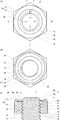
この実施の形態に係るナット20は、図1に示すように、ナット本体31とフリクションリング21とを備える。ナット本体31は鋼やステンレス製などの弾性の低い金属製などが適しており、フリクションリング21はバネ鋼製などの弾性の高い金属製などが適しているが、素材については本発明の目的を達成できる範囲で適宜変更することができる。
Hereinafter, embodiments of the present invention will be described with reference to the drawings.
As shown in FIG. 1, the
ナット本体31は、座面32とその反対側の上面33との間に雌ねじが形成されたもので、1条又は複数条のねじ山(以下、ナット本体31のねじ山を雌ねじ山34という)を備え、ボルト11と螺合する。ボルト11は、1条又は複数条のねじ山(以下、ボルト11のねじ山を雄ねじ山12といい、雌ねじ山34と雄ねじ山12とを区別する必要のない場合には、単にねじ山という。)を備える。雌ねじ山34は、通常のナットと同様、頂部37を挟んで軸方向の両側に形成された進み側フランク35及び追い側フランク36を備え、雌ねじ山34同士の間に谷底38を備える。雄ねじ山12は、通常のボルトと同様、頂部15を挟んで軸方向の両側に形成された進み側フランク13及び追い側フランク14を備え、雄ねじ山12同士の間に谷底16を備える。
ねじ山は、互いに螺合することを条件にその具体的形状は、一般のボルト・ナットと同様に種々変更して実施することができる。
The
The specific shape of the thread can be changed as long as it is screwed together.
ナット本体31の上面33には、フリクションリング21が取り付けられる。フリクションリング21は、環状の固定部22と、その内周側に突出するフリクション片23とを備える。弾性はフリクション片23にのみあればよいが、フリクションリング21全体を板状のバネ材で構成する方が生産上は効率的である。
The
このフリクションリング21を取り付けるために、ナット本体31の上面33にはかしめ部39が形成されている。このかしめ部39は環状であってもよく、周方向に断続的に設けられたものであってもよい。取り付け方法は、自由である。例えば、この種のフリクションナットの製法の常法に従って行うならば、曲げ加工する前のかしめ部39の内側におけるナット本体31の固定基準面40にフリクションリング21を載置して、かしめ部39を内周側に曲げ加工して、固定基準面40とかしめ部39との間に固定部22をかしめ止めすればよい。なお、固定手段は、熔接等の他の固定方法や構造に変更して実施することが可能である。
In order to attach the
上記の取り付けのために、固定部22は環状に形成され、フリクション片23は、ナット本体31のねじ穴内に突出している。これによって、ボルト11とナット20との螺合に際して、フリクション片23が雄ねじ山12に係合する。このフリクション片23の内径は、雄ねじ山12と係合してプリベリングトルクを発生し得ることを条件に変更することができるが、雄ねじ山12の山径以上、雄ねじ山12の谷径以下であることが適当である。なお、雌ねじ山34との関係では、雌ねじ山34の谷径以上、雌ねじ山34の山径以下であることが適当である。
For the above attachment, the
周方向については、この例では、フリクション片23はフリクションリング21における略350度の範囲に渡って固定部22から突出しており、移行部24が略10度の範囲に渡って形成されている。この周方向におけるフリクション片23の形成範囲は、大きい方がフリクション効果が高まると考えられる。ところが、従来、270度を越えると雄ねじ山12との干渉が著しく、280度を越えることは不可能であると考えれらていた。これに対して、本発明では、270度や280度を越えるものにあっても、雄ねじ山12との干渉を緩和して螺合でき、雄ねじ山12とナット20との自由回転を阻止する大きなプリベリングトルクを発生させることができるものであり、これを実現するための構造を以下に説明する。
Regarding the circumferential direction, in this example, the
従来のこの種のフリクションナットであれば、ナット本体31の固定基準面40と上面33とが面一であり、同じ高さに設定されていた。これに対して、本発明にあっては、固定基準面40と上面33との間に干渉防止用空間41を形成する。この実施の形態にあっては、従来、固定基準面40と面一であった上面33を、下方(座面32側)に穿設して凹部とすることによって、干渉防止用空間41を形成している。但し、かしめ部39を上方に高く伸ばして、固定基準面40を上面33よりも高い位置に形成するようにしてもよく、加工上有利な手段を選択して採用することができる。
In this type of conventional friction nut, the fixed
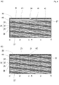
なお、図4(A)に示すように、フリクションリング21と、ナット本体31及びボルト11との周方向における位置関係は、次のように構成することが最も好ましいが、螺合に際して、ボルト11の雄ねじ山12が、移行部24の下方から侵入してフリクションリング21の上方に出るものであれば、次のものに限る必要はない。
As shown in FIG. 4A, the positional relationship in the circumferential direction between the
まず図4(B)の干渉防止用空間41を形成しない場合について説明する。フリクションリング21の移行部24と雄ねじ山12との周方向の位置関係では、雄ねじ山12の先端が、フリクションリング21の移行部24に良好に侵入していくように、両者の位置を設定する。そのためには、雄ねじ山12の先端がフリクションリング21に到達した際に、同先端が移行部24に位置するようにする。
First, a case where the
ここで、干渉防止用空間41を形成しない図4(B)の場合では、固定基準面40とナット本体31の上面33とが面一(同じ高さ)となるため、雄ねじ山12の先端がフリクションリング21に到達する位置と、雄ねじ山12の先端が上面33上に表われる位置とは同じになる。従って、雄ねじ山12の先端が上面33上に表われる位置を規定する切り上がり部42が、移行部24内に位置すればよい。言い換えれば、ナット本体31の上面33に、雌ねじ山34が表われる先端の位置を規定する切り上がり部42が、移行部24内に位置するように配置する。詳しくは、雌ねじ山34は、上面33から座面32に向けて、追い側フランク36と頂部37と進み側フランク35とによって規定され、雌ねじ山34と雌ねじ山34との間に谷底38が位置するため、切り上がり部42は、追い側フランク36の先端(追い側フランク36と谷底38との境界)に位置する。
Here, in the case of FIG. 4B in which the
これに対して、図4(A)に示すように、干渉防止用空間41を形成する場合にも、ボルト11がフリクションリング21の移行部24に侵入していく好ましい位置は変化せず、図4(B)の場合と同様、雄ねじ山12の先端がフリクションリング21に到達した際に、同先端が移行部24に位置するようにする。
On the other hand, as shown in FIG. 4A, when the
ところが、図4(A)に示すように、干渉防止用空間41を形成する場合には、フリクションリング21の位置を規定する固定基準面40よりも、上面33が低い位置(座面32寄りの位置)となるため、雄ねじ山12の先端が上面33上に表われても、雄ねじ山12の先端はフリクションリング21に到達しない。固定基準面40と上面33との高低差(例えば1/3ピッチ)分だけ、ねじが回転して、雄ねじ山12の先端はフリクションリング21に到達する。
However, as shown in FIG. 4A, when the
従って、本発明の図4(A)では、雄ねじ山12の先端が上面33上に表われる位置を規定する切り上がり部42は、固定基準面40と上面33との高低差(例えば1/3ピッチ)分だけ、移行部24からずれた位置に配置すればよい。言い換えれば、ナット本体31の上面33に、雌ねじ山34が表われる先端の位置を規定する切り上がり部42から、ねじ山のつる巻き線に沿って伸ばされた仮想線44が、移行部24内に位置するように配置する。詳しくは、追い側フランク36の先端(追い側フランク36と谷底38との境界)に位置する切り上がり部42から、ねじ山のつる巻き線に沿って伸ばされた仮想線44が、移行部24内に位置するように配置する。
Therefore, in FIG. 4A of the present invention, the rounded-up
上記のような周方向の位置関係に、フリクションリング21を配置した場合において、フリクションリング21、ボルト11及びナット本体31との関係を図2、図3を参照しながら説明する。
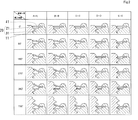
図2は、本発明の実施の形態に係る場合(即ち、干渉防止用空間41を設けた図4(A)の場合)を示すものである。横列は、同じ螺入角度にけおるボルト11とナット20との状態の断面図を、図1(A)の位置における5つの位置(A−A=約0度、B−B=90度、C−C=180度、D−D=270度、E−E=約360度)で配列したものである。また、縦列には、ボルト11がナット20に螺合するボルト11の螺入角度を、0度、90度、180度、270度、360度、720度とした状態の断面図を配列したものである。
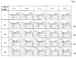
図3は、従来の形態に係る場合(即ち、干渉防止用空間41を設けない図4(B)の場合)を示すものである。横列は、図3と同様、同じ螺入角度にけおるボルト11とナット20との状態の断面図を、5つの位置(A−A=約0度、B−B=90度、C−C=180度、D−D=270度、E−E=約360度)で配列したものである。また、縦列には、ボルト11がナット20に螺合するボルト11の螺入角度を、0度、90度、180度、270度、360度とした状態の断面図を配列したものである。
When the
FIG. 2 shows the case according to the embodiment of the present invention (that is, the case of FIG. 4A in which an
FIG. 3 shows a case according to a conventional form (that is, a case of FIG. 4B in which no
まず、干渉防止用空間41を設けない場合(図3参照)から説明する。この場合、固定基準面40と上面33とが面一(同じ軸方向高さ)となっているため、フリクションリング21のフリクション片23とねじ山とが干渉して、実質的にボルト11とナット20とを螺合させることができない。
図3の縦列の変化から判るように、ボルト11がフリクションリング21に到達すると、徐々に、雄ねじ山12の進み側フランク13に沿ってフリクションリング21のフリクション片23が弾性変形して持ち上げられるようになる。その際、A−A断面だけを見ると、0度から360度まで徐々に持ち上がっていく。そして、A−A断面からD−D断面に移行することで、この持ち上がる状態は、ねじ山のつる巻き線に沿って少なくなることが判る。このD−D断面(即ち、A−A断面から周方向に270度の位置での断面)では、フリクション片23は上面33に当接した状態となり、その内周端は雄ねじ山12の谷底16に入り込んだ状態となっている。
First, the case where the
As can be seen from the change in the column of FIG. 3, when the
ところが、E−E断面では、フリクション片23は、上面33及び雄ねじ山12に干渉してしまう。この干渉部分43を、図3にて黒塗りで示す。より詳しくは、E−E断面では、フリクション片23は、本来、雄ねじ山12の追い側フランク14に案内されて、固定基準面40よりも下方に位置するように変形される状態となる。ところが、固定基準面40と上面33とが面一であるため、固定基準面40よりも下方に変形しようとしても、上面33が存在するため、下方に変形することができず、雄ねじ山12の追い側フランク14と干渉する。言い換えれば、上面33が位置すべき空間が、固定基準面40と雄ねじ山12とによって塞がれた状態となり、フリクション片23が存在し得なくなる。従って、螺入角度が比較的小さな段階では、ボルト11とナット本体31との公差の存在や、フリクション片23もしくは雄ねじ山12を傷つけることで、無理矢理にでも螺合を勧めることができるが、螺入角度が大きくなるに従って顕著となり、フリクション片23が固定基準面40と雄ねじ山12との間に挟まった状態となり、ねじの回転が進まなくなる。
However, in the EE cross section, the
これに対して、本発明の実施の形態に係る図2の場合には、固定基準面40の直下に上面33が存在せず、干渉防止用空間41が存在する。従って、E−E断面では、フリクション片23は、雄ねじ山12の追い側フランク14に案内されて、固定基準面40よりも下方に位置するように変形することができる。これによって、フリクション片23は、A−A断面では、雄ねじ山12の進み側フランク13に沿って最も顕著に弾性変形し、周方向に角度が進むごとに、変形が小さくなり、270度の位置での断面(D−D断面)では、フリクション片23は上面33と略同じ高さとなり、その内周端が雄ねじ山12の谷底16に入り込んだ状態となる。そして、本発明では干渉防止用空間41内が存在するため、E−E断面(即ち、A−A断面から周方向に進み側フランク350度の位置での断面)では、フリクション片23は上面33よりも下方に弾性変形することができる。これによって、フリクション片23は雄ねじ山12の追い側フランク14に沿うようになる。従って、図2の最下列である720度の螺入角度におけるA−A断面からE−E断面を順次見れば分かるように、フリクション片23は、雄ねじ山12の進み側フランク13と追い側フランク14とによって規定される同じ一連の谷空間に位置し、フリクション片23の周方向の前側(A−A断面〜C−C断面)では進み側フランク13の上に沿って弾性変形し、周方向の後側(E−E断面)では追い側フランク14の下に沿って変形した状態となる。これによって、ねじの回転を進めることができると共に,雄ねじ山12の上下両側から摩擦抵抗を加えることができ、従来よりも大きなプリベリングトルクを発生させることができる。
On the other hand, in the case of FIG. 2 according to the embodiment of the present invention, the
なお、設計上、前述の干渉が生じるおそれがあるのは、フリクション片23の形成範囲が一定の範囲を超えた場合である。
この一定の形成範囲の角度Xは、X=(1−b/p)×360で求められる(但し、b=ナット本体31における雌ねじ山34間の谷底38の軸方向長さ。p=雌ねじの1ピッチ。)。
The design may cause the above-described interference when the formation range of the
The angle X of this constant formation range is obtained by X = (1−b / p) × 360 (where b = the axial length of the valley bottom 38 between the
例えば、前述の各図は、谷底38の軸方向長さは、1/4ピッチのナット本体31を用いたものであり、X=3/4×360=270度を超えた範囲にフリクション片23が形成されると、干渉が生じるおそれが生じる。なお、実際には、これにねじの公差が加味されるため、約10度を加えて280度を越えた範囲にフリクション片23が形成されると、干渉が生じるそれがある。
For example, in each of the above-described drawings, the axial length of the valley bottom 38 uses the
なお、本発明は、種々変更して実施することができる。例えば、移行部24は、周方向に幅を持ったものとして実施しているが、実質的な面積を持たない線状の切込であってもよい。従って、この場合には、フリクション片23は約全周(理論的には360度未満)の角度となる。さらに、360度以上となって、フリクション片23の前端と後端とが重なる(接するか否かは問わない)ようであっても、前端と後端との間から雄ねじ山12の先端が侵入することができる場合には、実施することができる。特に、フリクションリング21を平面的な板状とせずに、一部又は全部をスパイラル状等の立体的な形状とすることによって、重なったフリクション片23の前端と後端との間から雄ねじ山12の先端を侵入させ移行させることができる。
The present invention can be implemented with various modifications. For example, although the
フリクション片23は、前述の例では、周方向に連続したものを示したが、周方向に複数に分断したものであってよい。前述の例で言えば、フリクション片23は、350度連続したものであってもよいが、例えば、これを約65度ずつ等に5分割等して、その間の約5度を分断された隙間とすることもできる。このようにフリクション片23を周方向へ複数に分割した場合でも、周方向において最前のフリクション片23から最後のフリクション片23間の形成範囲が270度(公差を考慮して280度を越える)を場合には、前述の干渉の問題が生じるおそれがあるが、本発明ではかかるおそれを抑制することができる。
In the above-described example, the
干渉防止用空間41については、先の例では、全周に形成したが、少なくとも、前述の干渉が生じる周方向の範囲(フリクション片23が固定基準面40よりも下方に変形する範囲)にのみ形成すればよい。具体的には、周方向における干渉防止用空間41の形成範囲は、Y=b/p×360で求められるY度以上とすることができる(但し、b=ナット本体31における雌ねじ山34間の谷底38の軸方向長さ。p=雌ねじの1ピッチ。)。例えば、前述の各図は、谷底38の軸方向長さは、1/4ピッチのナット本体31を用いたものであり、X=1/4×360=90度を超えた範囲にフリクション片23を形成すれば、干渉が生じるそれを解消できると考えられる。
In the previous example, the
干渉防止用空間41の軸方向長さは、干渉防止用空間41の突出長さや周方向の形成範囲の如何によって変化するが、雌ねじの谷底38の軸方向長さ以上の軸方向長さ雌ねじ山34の1/3ピッチ以上の軸方向長さがあれば充分である。勿論、前述の干渉を避けることができることを条件に、雌ねじの谷底38の軸方向長さ未満であってもよい。理論上では、この軸方向長さは、いくら大きくても干渉防止の観点からは問題はないが、一般的にナット20は同性能であれば小型のものが望ましいとされる場合が多いため、不必要にこの値を大きくする必要はない。より具体的には、例えば、谷底38の軸方向長さが1/4である場合には、若干の余裕を見て1/3程度の間隔を置けば安定した製品作りをなすことができる。
The axial length of the
また、干渉防止用空間41は軸方向と直交する平面として実施したが、固定基準面40から内周側に向かうに従って下方に傾斜した斜面や曲面として実施することもできるものであり、フリクション片23が変形できる空間が確保できることを条件に、その具体的な形状は種々変更して実施することができる。
Further, the
本発明は、フリクション片23の周方向の範囲が270度(交差を加えると280度)を超えた範囲で生じる前述の干渉を抑制することに一つの効果を見出せるものであるが、フリクション片23の周方向の範囲が270度(交差を加えると280度)以下の場合にあっても実施することができる。この場合、従来の干渉防止用空間がないものであっては、フリクションリング21の移行部24の位置を正確に設定しなければ、前述の干渉が生じるおそれがあったが、干渉防止用空間41を設けることによって、その位置の精度が低下した場合にあっても、干渉を生じるおそれを少なくすることができ、不良率の発生を抑えることができる。
The present invention can find one effect in suppressing the above-mentioned interference that occurs when the circumferential range of the
11 ボルト
12 雄ねじ山
13 進み側フランク
14 追い側フランク
15 頂部
16 谷底
20 ナット
21 フリクションリング
22 固定部
23 フリクション片
24 移行部
31 ナット本体
32 座面
33 上面
34 雌ねじ山
35 進み側フランク
36 追い側フランク
37 頂部
38 谷底
39 かしめ部
40 固定基準面
41 干渉防止用空間
42 切り上がり部
43 干渉部分
44 仮想線
11
Claims (5)
前記フリクション片のない移行部からボルトの雄ねじを侵入させ、前記フリクション片が侵入した雄ねじに係合して弾性変形することによりプリベリングトルクを発生させる緩み止めナットにおいて、
前記上面と前記フリクション片との間に軸方向に、前記フリクション片と前記雄ねじとの干渉を防止する干渉防止用空間が設けられたことを特徴とする緩み止めナット。 A nut body having a female screw and a seating surface, and a friction piece for generating a preveling torque fixed to the upper surface of the nut body facing the seating surface,
In the locking nut that causes the male screw of the bolt to enter from the transition portion without the friction piece, and generates the pre-torque torque by engaging with the male screw that the friction piece has entered and elastically deforming,
An anti-loosening nut characterized in that an interference preventing space for preventing interference between the friction piece and the male screw is provided in an axial direction between the upper surface and the friction piece.
前記フリクション片は、前記フリクション片の周方向の前側では前記進み側フランクの上に沿って変形し、前記フリクション片の周方向の後側では前記追い側フランクの下に沿って変形するものであることを特徴とする請求項1記載の緩み止めナット。 In the screwed state with the bolt, the friction piece is located in the same series of valley spaces defined by the follower flank and the advance flank of the bolt,
The friction piece is deformed along the advance side flank on the front side in the circumferential direction of the friction piece, and is deformed along the bottom side of the follower flank on the rear side in the circumferential direction of the friction piece. The locking nut according to claim 1, wherein:
[式1]X=(1−b/p)×360
但し、b=ナット本体の雌ねじの谷底の軸方向長さ。p=雌ねじの1ピッチ。 3. The locking nut according to claim 1, wherein the friction piece is formed over a range in the circumferential direction equal to or greater than X degrees of the following formula 1. 3.
[Formula 1] X = (1-b / p) × 360
Where b = the axial length of the bottom of the female thread of the nut body. p = one pitch of female thread.
[式2]Y=b/p×360
但し、b=ナット本体の雌ねじの谷底の軸方向長さ。p=雌ねじの1ピッチ。 The interference prevention space according to any one of claims 1 to 4, wherein the interference prevention space is formed over a range in a circumferential direction equal to or less than Y degrees of the following equation (2).
[Formula 2] Y = b / p × 360
Where b = the axial length of the bottom of the female thread of the nut body. p = one pitch of female thread.
Priority Applications (1)
| Application Number | Priority Date | Filing Date | Title |
|---|---|---|---|
| JP2013245103A JP2015102207A (en) | 2013-11-27 | 2013-11-27 | Lock nut |
Applications Claiming Priority (1)
| Application Number | Priority Date | Filing Date | Title |
|---|---|---|---|
| JP2013245103A JP2015102207A (en) | 2013-11-27 | 2013-11-27 | Lock nut |
Publications (1)
| Publication Number | Publication Date |
|---|---|
| JP2015102207A true JP2015102207A (en) | 2015-06-04 |
Family
ID=53378066
Family Applications (1)
| Application Number | Title | Priority Date | Filing Date |
|---|---|---|---|
| JP2013245103A Pending JP2015102207A (en) | 2013-11-27 | 2013-11-27 | Lock nut |
Country Status (1)
| Country | Link |
|---|---|
| JP (1) | JP2015102207A (en) |
Cited By (1)
| Publication number | Priority date | Publication date | Assignee | Title |
|---|---|---|---|---|
| JP2021124121A (en) * | 2020-01-31 | 2021-08-30 | 株式会社ケー・エフ・シー | Fastening anchor and construction method therefor |
Citations (5)
| Publication number | Priority date | Publication date | Assignee | Title |
|---|---|---|---|---|
| JPS50141056U (en) * | 1974-05-10 | 1975-11-20 | ||
| JPS57109316U (en) * | 1980-12-25 | 1982-07-06 | ||
| JPS57179413A (en) * | 1981-04-30 | 1982-11-05 | Sakamura Machine | Locking nut |
| JPS5937417U (en) * | 1982-09-02 | 1984-03-09 | 株式会社サト−ラシ | Loosening nut |
| JPH08232941A (en) * | 1995-02-28 | 1996-09-10 | Yuusu Kitaura:Kk | Nut, engaging member and screw structure |
-
2013
- 2013-11-27 JP JP2013245103A patent/JP2015102207A/en active Pending
Patent Citations (5)
| Publication number | Priority date | Publication date | Assignee | Title |
|---|---|---|---|---|
| JPS50141056U (en) * | 1974-05-10 | 1975-11-20 | ||
| JPS57109316U (en) * | 1980-12-25 | 1982-07-06 | ||
| JPS57179413A (en) * | 1981-04-30 | 1982-11-05 | Sakamura Machine | Locking nut |
| JPS5937417U (en) * | 1982-09-02 | 1984-03-09 | 株式会社サト−ラシ | Loosening nut |
| JPH08232941A (en) * | 1995-02-28 | 1996-09-10 | Yuusu Kitaura:Kk | Nut, engaging member and screw structure |
Cited By (2)
| Publication number | Priority date | Publication date | Assignee | Title |
|---|---|---|---|---|
| JP2021124121A (en) * | 2020-01-31 | 2021-08-30 | 株式会社ケー・エフ・シー | Fastening anchor and construction method therefor |
| JP7429382B2 (en) | 2020-01-31 | 2024-02-08 | 株式会社ケー・エフ・シー | Tightening anchor and its construction method |
Similar Documents
| Publication | Publication Date | Title |
|---|---|---|
| JP6263751B2 (en) | bolt | |
| JP5784598B2 (en) | Lock nut | |
| US11795990B2 (en) | Anti-loosening screw pair and anti-loosening screw component | |
| US9181972B2 (en) | Loosening prevention threaded fastener | |
| JP5655208B2 (en) | Seizure prevention bolt | |
| US20170184144A1 (en) | Washer for preventing loosening | |
| CN104235162B (en) | Anti-loosening screw | |
| JP2010516960A (en) | Preload locking wire insert | |
| JP2015052369A (en) | Bolt / nut locking structure | |
| JP6239651B2 (en) | Tapping screw | |
| JP6550512B2 (en) | Locking member for nut and nut | |
| JP6224991B2 (en) | Tapping screw | |
| JP4384197B2 (en) | Locking nut | |
| JP5289545B2 (en) | Nut, bolt and nut fastening structure | |
| CN113251054B (en) | External screw member | |
| JP6395654B2 (en) | Nut, bolt and nut fastening structure | |
| JP2011252593A (en) | Slack preventing screw | |
| JP2016156400A5 (en) | ||
| JPWO2013080327A1 (en) | Tapping screw | |
| JP6200114B1 (en) | Locking screw | |
| JP3946752B1 (en) | Locking nut | |
| JP6347367B2 (en) | Locking nut | |
| JP2015203493A (en) | Bolt | |
| JP2012057667A (en) | Nut | |
| JP6231796B2 (en) | Bolt / nut locking structure |
Legal Events
| Date | Code | Title | Description |
|---|---|---|---|
| A621 | Written request for application examination |
Free format text: JAPANESE INTERMEDIATE CODE: A621 Effective date: 20150702 |
|
| A977 | Report on retrieval |
Free format text: JAPANESE INTERMEDIATE CODE: A971007 Effective date: 20160420 |
|
| A131 | Notification of reasons for refusal |
Free format text: JAPANESE INTERMEDIATE CODE: A131 Effective date: 20160426 |
|
| A521 | Written amendment |
Free format text: JAPANESE INTERMEDIATE CODE: A523 Effective date: 20160624 |