JP2015114804A - Intelligent water and water distribution control system - Google Patents
Intelligent water and water distribution control system Download PDFInfo
- Publication number
- JP2015114804A JP2015114804A JP2013255733A JP2013255733A JP2015114804A JP 2015114804 A JP2015114804 A JP 2015114804A JP 2013255733 A JP2013255733 A JP 2013255733A JP 2013255733 A JP2013255733 A JP 2013255733A JP 2015114804 A JP2015114804 A JP 2015114804A
- Authority
- JP
- Japan
- Prior art keywords
- water
- distribution
- plan
- water distribution
- planning
- Prior art date
- Legal status (The legal status is an assumption and is not a legal conclusion. Google has not performed a legal analysis and makes no representation as to the accuracy of the status listed.)
- Granted
Links
Images

Landscapes
- Management, Administration, Business Operations System, And Electronic Commerce (AREA)
Abstract
Description
本発明は、水運用計画の立案および配水制御を実行するシステムに関する。 The present invention relates to a system for executing a water operation plan and water distribution control.
以下の特許文献1には、送水ポンプの運転に適している運転スケジュールを策定することができるようにする技術が記載されている。
The following
また、以下の特許文献2には、リアルタイムのプロセスデータにより配水管網の状態をシミュレーションし、各配水注入点を含む操作点に対して最適な操作量を自動的に算出して設定可能な配水コントロールシステムを実現する技術が記載されている。
Further, in
上記の特許文献1に記載の送水運用制御装置では、送水系統を構成している配水池における水需要量を満足するように、送水系統においてポンプの動力コストが最小の運転スケジュールを策定することができる。しかしながら、配水池から先に存在する個々の需要家に対して配水するための配水系統におけるポンプの運転スケジュールには言及していない。そのため、配水系統が多点注入の系である場合、当該特許文献1の技術により定められた配水池の容量に従い配水すると、送配水系統全体で動力コストが最小ではないことがある。
In the water supply operation control device described in
他方、上記の特許文献2に記載の配水コントロールシステムでは、複数の配水注入点を有する配水管網において、入力された配水計画に基づいて末端圧が一定であるようにポンプの操作量を決定できる。しかしながら、消費電力量については言及されておらず、決定したポンプの操作量が消費電力最小の運用を達成できるとは限らない。
On the other hand, in the water distribution control system described in
そこで、本発明は、上述した従来技術における問題点を解消するためになされたものであり、その目的は、送配水系統全体で消費電力量が最小となる送水ポンプおよび配水ポンプの運転スケジュールの決定を実現するための配水計画が立案可能な水運用および配水制御システムを提供することにある。 Therefore, the present invention has been made to solve the above-described problems in the prior art, and its purpose is to determine a water supply pump and a distribution pump operating schedule that minimize power consumption in the entire transmission and distribution system. It is to provide a water operation and distribution control system that can formulate a water distribution plan for realizing the above.
上述した目的を達成するため、本発明によれば、例えば、請求項にも記載するように、取水から需要家までの送配水系と、前記送配水系を制御する計画装置と、前記計画装置に接続された記憶装置群と、前記計画装置との間で信号を送受信する入出力装置とから成る水運用および配水制御システムであって、前記計画装置は、配水所から需要家までの配水系において、ポンプの吐出圧、及び、配水所からの配水量の計画である配水計画を立案する配水制御部と、取水源から配水所までの送水系における管路内の流量の計画である水運用計画を立案する水運用計画立案部と、前記水運用計画立案部及び前記配水制御部の立案結果を修正する連携部と、を備えており、前記計画装置は、前記配水制御部、前記水運用計画立案部、及び、前記連携部の処理を反復して実行することで、目的関数が最小のポンプの運転スケジュールを定めるための送配水計画を立案する処理を実行する水運用および配水制御システムが提供される。 In order to achieve the above-described object, according to the present invention, for example, as described in the claims, a transmission / distribution system from intake water to a consumer, a planning device for controlling the transmission / distribution system, and the planning device A water operation and distribution control system comprising a storage device group connected to the I / O device and an input / output device that transmits and receives signals to and from the planning device, wherein the planning device is a water distribution system from a water distribution station to a consumer. Water supply control unit that formulates a water distribution plan that is a plan of the discharge pressure of the pump and the amount of water distribution from the water distribution station, and water operation that is a plan of the flow rate in the pipeline in the water transmission system from the water intake source to the water distribution station A water operation plan planning unit for formulating a plan; and a cooperation unit for correcting the planning results of the water operation plan planning unit and the water distribution control unit, and the planning device includes the water distribution control unit and the water operation Planning department and the cooperation department By iteratively performing processing, water management and distribution control system executing the process of drafting a water distribution plan for the objective function defines the operation schedule of the smallest pump being provided.
上述した本発明によれば、送配水系統全体で消費電力量が最小となる送水ポンプおよび配水ポンプの運転スケジュールの決定が可能で、かつ、それを実現する配水計画を立案することが可能な水運用および配水制御システムが提供される。 According to the above-described present invention, it is possible to determine the water supply pump and the operation schedule of the water distribution pump that minimize the power consumption in the entire water distribution system, and to make a water distribution plan that can realize the water supply plan. An operational and water distribution control system is provided.
以下、本発明の実施の形態について、図面を参照しながら詳細に説明する。 Hereinafter, embodiments of the present invention will be described in detail with reference to the drawings.
第一の実施形態(実施例1)について、図1を参照しながら説明する。
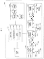
図1は、本発明の実施例1になる水運用および配水制御システムの全体構成を示すブロック図である。図からも明らかなように、このシステムは1000、概略すれば、計画装置1001と、記憶装置群1002と、送配水系1003と、入出力装置1004とから成る。以下、各構成要件について、更に詳細に説明する。
The first embodiment (Example 1) will be described with reference to FIG.
FIG. 1 is a block diagram showing an overall configuration of a water operation and water distribution control system according to
まず、計画装置1001は、後述の配水制御処理を実行する配水制御部1011と、後述の水運用計画立案処理を実行する水運用計画立案部1021と、後述の連携処理を実行する連携部1031と、そして、前記記憶装置群1002及び送配水系統1003とデータ及び制御信号の送受信を行う入出力部1041とから構成される。なお、各部の処理については、後述する。また、計画装置1001は、当該装置を動作させるためのソフトウェア等を格納するための内部メモリ及び演算装置を備えている。
First, the
記憶装置群1002は、送配水系データ記憶装置1012、需要パターン記憶装置1022、計算条件データ記憶装置1032、及び、運用実績データ記憶装置1042から成る。より具体的には、この記憶装置群1002において、前記記憶装置1012は送水系統および配水系統(以下、まとめて「送配水系統」と呼ぶ)を構成する送配水設備のデータを記憶している。なお、詳細は後述する。
The
次に、送配水系1003は、少なくとも1つ以上の配水所1013と、やはり少なくとも1つ以上の配水管網1023とから構成されており、各配水所1013は、配水所制御装置1113、配水ポンプ1213、及び、配水池1313から構成されている。また、各配水管網1023は、配水所からの供給先である需要家1223、需要家と配水所を接続するための配水管1123、及び、配水管分岐点1323から構成されている。
Next, the
また、送配水系1003は、更に、送水管1033と、送水管分岐点1043と、浄水場1053と、配水池1063と、送水ポンプ1073を含んで構成されている。
入出力装置1004は、上記計画装置1001のユーザに情報を表示し、又は、ユーザの命令を受信するための装置である。
Further, the water supply /
The input /
なお、以下では、配水所1013と配水管網1023から成る系を「配水系統」と呼び、各配水所1013内の配水池1313と、そして、配水所外に存在する送水管1033、送水管分岐点1043、浄水場1053、送水ポンプ1073、及び、配水池1063とから成る系を「送水系統」と呼ぶ。
Hereinafter, a system composed of the
また、ユーザとは、本システムを用いて計画立案を実施する人間であり、例えば、浄水場の運転員などが該当する。 Moreover, a user is a person who implements a plan using this system, for example, the operator of a water purification plant etc. correspond.
また、上記の図では、簡便のため、配水所の符号を一部省略しているが、当該図1の例では、配水所1013は4か所に、配水管網1023は2つが存在している。
Further, in the above diagram, for the sake of simplicity, some of the codes of the water distribution stations are omitted, but in the example of FIG. 1, there are four
ここで、記憶装置群1002を構成する各記憶装置の詳細について説明する。
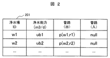
図2は、当該記憶装置1012が記憶する、浄水場1053を含む浄水場に関するデータ(浄水場データ)の構造の一例を示す。図のテーブル201にも示す通り、各浄水場は、固有のIDと、日量あたりの浄水量を定めた浄水能力と、浄水場に入る管および浄水場から出る管IDとを、それぞれ、記憶している。
Here, details of each storage device constituting the
FIG. 2 shows an example of the structure of data (water purification plant data) related to the water purification plant including the
図3は、やはり、上記記憶装置1012が記憶する、配水系統の配水池1313、又は、送水系統の配水池1063を含む配水池に関するデータ(配水池データ)の構造の一例を示す。図のテーブル301にも示す通り、各配水池は、固有のIDと、後述する水運用計画立案処理、又は、後述する配水制御処理において入力とする初期水位と、配水池に入る管および配水池から出る管と、後述する制約を定めるための下限水位および上限水位とを、それぞれ、記憶している。
FIG. 3 also shows an example of the structure of data (reservoir data) relating to a reservoir including the
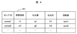
図4も、同様に、上記記憶装置1012が記憶する、配水ポンプ1213、又は、送水ポンプ1073のデータ(ポンプデータ)の構造の一例を示す。図のテーブル401にも示す通り、各ポンプは、固有のIDと、ポンプが設置されている施設と、ポンプから送水または配水可能な吐出流量の上限と、ポンプの吐出圧の上限と、ポンプの回転数を、それぞれ、記憶している。なお、このテーブル401は、前記吐出圧、吐出流量、及び/又は、回転数の時系列のデータを記憶してもよい。また、その他、インバータ効率やモータ効率などポンプ特有のデータを記憶してもよい。
4 also shows an example of the structure of data (pump data) of the
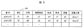
図5は、上記記憶装置1012が記憶する、配水管1123、及び、送水管1033を含む、送配水管路に関するデータ(管データ)の構造の一例を示す。図のテーブル501にも示す通り、各管は、固有のIDと、管の長さと、管の口径と、管網解析において用いる管路抵抗と、管の始点および管の終点を、それぞれ、記憶している。さらに、管を流れる水の流量および流量の上限を記憶している。ここで、水の流量は、単一の値ではなく時系列の値を記憶してもよい。
FIG. 5 shows an example of the structure of data (pipe data) related to the water supply / distribution pipe line, including the
また、テーブル501に記載されるIDは、括弧の中の第一引数が管の始点であり、第二引数が終点であることを意味する。加えて、引数は頂点でなければならない。ここで、頂点とは、例えば、浄水場、配水池、ポンプ、送水管分岐点、配水管分岐点、又は、需要家の何れかである。例えば、テーブル501における「p(w1,r1)」は、浄水場「w1」が始点であり、配水池「r1」が終点であるように接続した管を意味する。 The ID described in the table 501 means that the first argument in parentheses is the start point of the pipe and the second argument is the end point. In addition, the argument must be a vertex. Here, the apex is, for example, one of a water purification plant, a water reservoir, a pump, a water pipe branch point, a water pipe branch point, or a customer. For example, “p (w1, r1)” in the table 501 means a pipe connected so that the water purification plant “w1” is the start point and the water reservoir “r1” is the end point.
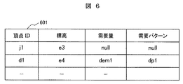
図6は、上記記憶装置1012が記憶する、配水管分岐点1323、送水管分岐点1043、及び、需要家1223を含む分岐点・需要家に関するデータ(頂点データ)の構造の一例を示す。図のテーブル601には、配水管分岐点又は送水管分岐点と、需要家のデータが記憶される。
FIG. 6 shows an example of the structure of data (vertex data) related to branch points / customers including the distribution
より具体的に述べると、前記分岐点を意味する場合には、前記分岐点が持つ固有のIDと、分岐点の標高と、そして、需要量が設定されていないことを意味する文字列である「null」を記憶する。他方、前記需要家を意味する場合は、需要家の固有のIDと、需要家の標高と、需要量と、後述する需要量データに記載される需要パターンへの参照「dp1」が記憶される。
記憶装置群1002を構成する他の記憶装置である上記記憶装置1022は、各需要家が持つ一日の需要量パターンを記憶している。
More specifically, when it means the branch point, it is a character string that means that the unique ID of the branch point, the elevation of the branch point, and the demand amount are not set. Remember "null". On the other hand, when referring to the consumer, the unique ID of the consumer, the elevation of the consumer, the demand amount, and a reference “dp1” to the demand pattern described in the demand amount data described later is stored. .
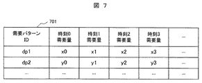
The
図7は、上記需要量パターンのデータ構造の一例を示す。図のテーブル(需要パターン)701にも示す通り、各需要パターン毎に、固有のIDが設定されており、そして、一日の中で設定された各時刻における需要量を、それぞれ、記憶している。ここで時刻とは、一時間を単位として以降の実施例を記載するが、しかしながら、本発明はこれに限定されることなく、例えば、分単位や二時間以上を単位としてもよい。 FIG. 7 shows an example of the data structure of the demand pattern. As shown in the table (demand pattern) 701, a unique ID is set for each demand pattern, and the demand amount at each time set in the day is stored. Yes. Here, the time is described in the following examples in units of one hour. However, the present invention is not limited to this, and may be in units of minutes or two hours or more, for example.
また、上記の記憶装置1032は、後述の計画装置が実行する処理の計算条件を記憶している。ここで、計算条件とは、例えば、前記送配水設備を動作させたときの各々の消費電力量を計算するための計算式や、管網において成立しなければならない水理条件を記述する式、処理の要所で用いる定数などが該当する。加えて、当該記憶装置1032は、図8に示す配水計画を記憶している。
The
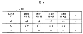
図8に一例を示す配水計画とは、配水所に設置された配水池からの、単位時間当たりの配水量を記述した計画である。テーブル801にも示した通り、各配水所毎に、ある時刻における配水量を記載したテーブルの形で表現する。なお、計画装置1001は、後述するように、当該装置が実行する処理において、配水計画を立案する。
The water distribution plan shown as an example in FIG. 8 is a plan that describes the amount of water distribution per unit time from a water reservoir installed in a water distribution station. As shown in the table 801, the amount of water distribution at a certain time is expressed in the form of a table for each water distribution station. In addition, the
また、上記の記憶装置1042は、浄水場、配水池、送水ポンプ、又は、配水ポンプが稼動した際の実績値(例えば、実際の配水量など)を記憶する。その他、管毎の個別の流量などを記憶してもよい。なお、この記憶装置1042が記憶するデータ構造は、前記テーブル201などと同一の形式であり、但し、格納する値は実績値となる。
Moreover, said memory |
ここで、再び上記図1に戻り、上述した送配水系統1003は、計画装置1001の処理結果を受けて動作する、送配水のための施設及び需要家である。また、各送配水系は、後述する計画装置の処理において決定された水運用計画に基づき、以下のように動作する。
(a)浄水場1053は、単位時間当たりの送水量として定められた量の上水を、造水する。
(b)送水ポンプ1073は、上記の上水を圧送により配水池へ送水する。
(c)本システムが送水ポンプ又は配水ポンプを用いずに送水する場合は、自然流下により送水を行う。
(d)配水所1013は、自然流下又は配水ポンプを用いた圧送により、配水管網へ配水し、需要家1223へ上水を供給する。なお、配水ポンプ1073の運転は、配水所1013が保持する配水所制御装置1113が行う。
Here, returning to FIG. 1 again, the above-described transmission and
(A) The
(B) The
(C) When this system supplies water without using a water pump or a water distribution pump, water is supplied by natural flow.
(D) The
そして、前記入出力装置1004は、例えば、キーボードやポインティングデバイス等の入力装置と、後述する計画装置の処理の結果、及び、送配水設備のデータを表示する出力装置から構成される。
The input /
以下、上記にその構成を説明した水運用および配水制御システム1000において、上記計画装置1001が有する配水制御部1011、水運用計画立案部1021、連携部1031、及び、入出力部1041が実行する処理について、添付の図9を参照しながら、
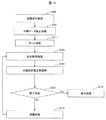
説明する。なお、当該処理は、入出力装置1041が、ユーザから受信した起動信号を前記計画装置1001の入出力部1041に送信し、当該入出力部1041が受信することで実行される。そして、計画装置1001は、図9に記載のフローチャートに従って動作する。
Hereinafter, in the water operation and
explain. The processing is executed by the input /
計画装置1001は、起動信号を受信した後(ステップS100)、処理(ステップS101)において、上記記憶装置群1002が保持するデータを、ユーザの必要に応じて、手動で修正する。
After receiving the activation signal (Step S100), the
続いて、ユーザは、入出力装置1004を介して、上記で修正後の送配水系データ、需要家パターンデータ、及び/又は、計算条件データを、計画装置1001の入出力部1041へ送信する。この時、計画装置1001は、かかるデータを受信すると(データ受信:ステップS111)、記憶装置群1002が保持するデータを更新する働きをする。
Subsequently, the user transmits the corrected transmission / distribution system data, customer pattern data, and / or calculation condition data to the input /
次に、記憶装置群1002から、処理に必要なデータを内部メモリに読み込む。具体的には、送配水系データ、需要パターンデータ、及び/又は、計算条件データである。
Next, data necessary for processing is read from the
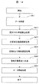
次いで、計画装置1001は、配水制御処理を実行し(ステップS121)、更に、水運用計画立案処理を実行する(ステップS131)。
Next, the
その後、終了判定を行い(ステップS141)、その結果、終了条件を満たしているならば(「Yes」)、処理結果を入出力装置1004へ送信して表示処理する(ステップS151)。それ以外の場合には(「No」)、計画装置1001は、上記ステップS104の配水制御処理の結果、及び、ステップS131の水運用計画立案処理の結果を、連携処理(ステップS161)した後、再度、配水制御処理(ステップS121)及び水運用計画立案処理(ステップS131)を実行し、これを、終了条件を満たす(「Yes」)まで繰り返し、表示処理する(ステップS151)。
Thereafter, an end determination is made (step S141), and as a result, if the end condition is satisfied (“Yes”), the processing result is transmitted to the input /
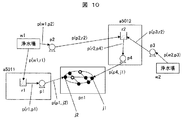
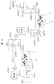
続いて、上述した計画装置1001における処理の詳細について、送配水系統の一例を示す図10を用いて説明する。ここでは、各浄水場「w1」及び「w2」が上水を、矢印で表現した各送水管、及び、ポンプ「p2」と「p3」を経由して、配水所「a5011」と「a5012」に設置された配水池「r1」及び「r2」へ送水する。その後、各配水所は、ポンプ「p1」又は「p4」、配水管「p(p1,j2)」又は「p(p4,j1)」、及び、配水管網「pn1」を経由して、需要家へ上水を供給する。なお、ここでは、説明の簡単のため、或る配水所と配水管網をつなぐ管は、丁度、一つであるとして図示している。
Then, the detail of the process in the
図10に示すように、配水所「a5011」は、ポンプ「p1」と配水管分岐点「j2」を結ぶ管で、配水所「a5012」は、ポンプ「p4」と配水管分岐点「j1」を結ぶ管で、それぞれ、配水管網「pn1」に接続されている。但し、更に複雑な送配水系統に適用する際には、或る配水所から配水管網へ複数の管により接続してもよい。 As shown in FIG. 10, the water distribution station “a5011” is a pipe connecting the pump “p1” and the distribution pipe branch point “j2”, and the water distribution station “a5012” is the pump “p4” and the distribution pipe branch point “j1”. Are connected to the distribution network “pn1”. However, when applied to a more complicated transmission and distribution system, a plurality of pipes may be connected from a certain distribution station to a distribution pipe network.
(1)配水制御処理
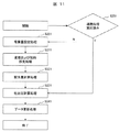
図11は、計画装置1001が配水制御部1011で実行する「配水制御処理」(図9のS121を参照)の詳細を示すフローチャートである。即ち、計画装置1001は、当該処理において、後述する連携処理が実行済みか否かを判定する(ステップS251)。判定の結果、実行済み(「Yes」)である場合には、計画装置1001は、後述の吐出圧力計算処理(ステップS201)以下の処理を実行し、そうでない場合(「No」)は後述の需要量設定処理(ステップS231)以下の処理を実行する。
(1) Water Distribution Control Process FIG. 11 is a flowchart showing details of the “water distribution control process” (see S121 of FIG. 9) executed by the
より具体的には、計画装置1001は、需要量設定処理(ステップS201)において、上述した図9のデータ受信処理(ステップS111)で受信した需要パターンデータを基に、配水管網「pn1」へ供給する上水の総量「Dem_{pn_i}」を、以下の式1により計算する。
More specifically, the
なお、これらは、計算装置1001が読み込んだ送配水系統データ内に格納されており、例えば、上記図6のテーブル601に記載された「需要量パターン」の該当時刻を参照することで得られる。
ここで、上記式1は、一般的に記述するために、配水管網を「pn_i」としているが、上記図10の例では、丁度一つの配水管網「pn1」が存在するのみである。そのため、説明の都合上、単に、これを「pn1」として、式を記述することもある。
These are stored in the transmission and distribution system data read by the
Here, for the sake of general description, the above-described
また、計画装置1001は、計算した値「Dem_{pn_i}」を、当該装置が保持するメモリ内に格納する。加えて、単位時間毎の需要「Dem_{pn_i}(t)」を、以下の式2により計算した後、その結果を自身が保持するメモリに格納する。
In addition, the
次に、計画装置1001は、変数および制約設定処理(ステップS211)において、上記図9の配水制御処理(ステップS121)において装置が決定する変数および変数を決定するにあたり課せられる制約を設定する。
Next, in the variable and constraint setting process (step S211), the
また、上記図9の配水制御処理(ステップS121)においては、配水計画も決定する。即ち、計画装置1001が、後述するが、配水量および配水所の吐出圧を決定変数とした最適化問題を生成し、そして、当該装置が配水量計算処理(ステップS221)を実行して前記問題を解くことで、配水計画を生成する。
Further, in the water distribution control process (step S121) of FIG. 9, a water distribution plan is also determined. That is, as will be described later, the
即ち、上述した計算条件データ記憶装置1032は、或る配水所「r」が時刻「t」において配水する量「q_{r,t}」を、以下の式3の形で定めるモデルを記憶している。加えて、当該記憶装置は、吐出圧を「h_{r,t}」とし、以下の式4の形で定めるモデルを記憶している。
That is, the calculation condition
次に、計画装置1001は、上述した記憶装置1032が記憶している制約データに従い、制約を設定する。即ち、計画装置は、送配水系データおよび前記の配水管網の需要量(本例では、「Dem_pn1」及び「Dem_pn1(t))」を基に、制約を構成する。
まず、各配水管網における一日の需要量満たす必要がある。これは、以下の式5の通り設定する。
Next, the
First, it is necessary to meet the daily demand in each distribution pipe network. This is set as shown in Equation 5 below.
即ち、計画装置1001は、以上の制約のもとで、各時刻「t」における各配水所「r_i」のポンプ消費電力量「f(r_i,t)」の総和を最小化するよう、前記「q_{r,t}」を決定する最適化問題を解く。
That is, the
また、上述した記憶装置1032は、消費電力量を最小化する目的関数を、以下の式6の形で記憶している。
Further, the
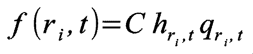
なお、当該記憶装置、時刻「t」における或る配水所「r_i」のポンプの消費電力量を計算するモデルとして、「f(r_i,t)」の計算方法を、以下の式7として記憶している。 Note that the calculation method of “f (r_i, t)” is stored as the following equation 7 as a model for calculating the power consumption of the pump of a certain water distribution station “r_i” at the time “t”. ing.
上記式7は簡易的なモデルであり、計算条件データ記憶装置1032が記憶する目的関数は、より精緻な目的関数としてもよい。例えば、配水所が複数のポンプを含む場合、各々のポンプの台数や組合せ、各ポンプの回転数、効率の変化を変数として持つように記憶してもよい。なお、吐出圧の計算については、後述する。
Equation 7 is a simple model, and the objective function stored in the calculation condition
吐出圧は、或る配水管網「pn」へ供給する各配水所の配水量バランスに応じて変化する。そのため、或る配水管網「pn」へ供給する各配水所「r_i」からの供給量「q_{r_1}」と、「pn」へ供給するための消費電力量を対応させた表を用意し、それを用いて消費電力量を近似的に計算する。 The discharge pressure varies according to the distribution amount balance of each distribution station supplied to a certain distribution pipe network “pn”. Therefore, a table is prepared in which the supply amount “q_ {r_1}” from each water distribution station “r_i” supplied to a certain distribution pipe network “pn” is associated with the power consumption amount supplied to “pn”. Using this, the power consumption is approximately calculated.
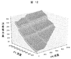
例えば、「pn1」へ供給する配水所「a5011」及び配水所「a5012」の配水量と、そのときの消費電力量は、図12に示すように、3次元のグラフで表せる。なお、このようなグラフは、既存の技術である管網計算を様々な条件の配水計画に対してシミュレーションした結果を、計算条件データに予め格納しておくことで作成できる。また、上述した運用実績データ記憶装置1042が記憶している運用実績を基に作成することもできる。また、配水所が3つ以上に増えた場合でも、前記と同様に、各配水所からの配水量バランスと消費電力量の対応グラフを作成することができる。そして、上記グラフを用いることで、各時刻「t」において、消費電力量が最小の配水量バランスを決定できる。
For example, the water distribution amount of the water distribution station “a5011” and the water distribution station “a5012” supplied to “pn1” and the power consumption at that time can be represented by a three-dimensional graph as shown in FIG. In addition, such a graph can be created by storing the result of simulating pipe network calculation, which is an existing technology, for water distribution plans under various conditions in calculation condition data in advance. Further, it can be created based on the operation results stored in the operation result
続いて、計画装置1001は、吐出圧計算処理(ステップS231)において、上述した配水計画で定められた配水量に応じて、配水管網内で低圧点を発生させないように配水するためのポンプの吐出圧を決定する。なお、ここで、配水量が既知の下でそのような吐出圧を決定することは、既に、上記の特許文献2や、その他、例えば、管網計算を用いた配水制御に関する既存技術により可能であるため、その詳細については割愛する。
即ち、計画装置1001は、上述したように、管網計算を用いた既存技術により、吐出圧を決定する。
Subsequently, in the discharge pressure calculation process (step S231), the
That is, as described above, the
その後、計画装置1001は、最後に、データ更新処理(ステップS241)により、これまでに計算対象とした送配水系統の設備のデータを、上述した計算結果に従って、更新する。具体的には、計画装置が、生成した配水計画を計算条件データ記憶装置に保存する。加えて、計画装置は、管網計算時に算出された水理条件を送配水系データ記憶装置に保存する。
Thereafter, the
ここで、水理条件とは、管を水が流れるに当たり満たすべき条件のことであり、少なくとも、管の時刻毎の流量及び流速と、各管分岐点と需要家での水圧が含まれる。また、当該水理条件に加え、各管分岐点と需要家での損失水頭などの他の情報を保存してもよい。 Here, the hydraulic condition is a condition to be satisfied when water flows through the pipe, and includes at least a flow rate and a flow rate at each time of the pipe, and a water pressure at each pipe branch point and the customer. In addition to the hydraulic conditions, other information such as each branch point and the loss head at the customer may be stored.
(2)水運用計画立案処理
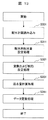
図13は、計画装置1001が、上記の水運用計画立案部1021にて実行する水運用計画立案処理(上記図9のステップS131)の詳細を示すフローチャートである。
水運用計画によれば、送水系の末端に存在する配水池に設定された需要量を満たすように、浄水場からその配水池までの管の流量を決定することで立案できる。ここで、需要量とは、単位時間あたりのその配水池からの配水量と等しい。
(2) Water Operation Planning Process FIG. 13 is a flowchart showing details of the water operation planning process (step S131 in FIG. 9) executed by the
According to the water operation plan, it can be planned by determining the flow rate of the pipe from the water treatment plant to the reservoir so as to satisfy the demand set for the reservoir existing at the end of the water transmission system. Here, the demand amount is equal to the amount of water distributed from the reservoir per unit time.
処理を開始すると、計画装置1001は、まず、上記配水制御部1011での処理の後に計算条件データ記憶装置1032に保存された配水計画を読み込む(ステップS301)。
When the processing is started, the
次いで、計画装置は、上記で読み込んだ配水計画を基に、配水池の1時間毎の需要量を設定する(配水所配水量設定処理:ステップS311)。例えば、上記で読み込んだ配水計画を基に、配水池「r1」の時刻「0」の需要量を「q0」、時刻「1」の需要量を「q1」、と設定する。このようにして需要量を設定した後、計画装置1001は、更に、水運用計画を立案するための最適化問題の定式化を行う。
Next, the planning device sets the hourly demand amount of the distribution reservoir based on the water distribution plan read above (water distribution station water amount setting processing: step S311). For example, based on the distribution plan read above, the demand amount at time “0” of the distribution reservoir “r1” is set to “q0”, and the demand amount at time “1” is set to “q1”. After setting the demand in this way, the
ここでは、計画装置1001が上記図9にステップS111で示したデータ受信処理で読み込んだ送配水系データのうち、送水系データを対象として処理を行う。
Here, the
前記データのうち、例えば、各送水管「p」の時刻「t」の流量「q_{p,t}」を決定変数とする。具体的には以下の式8で定められる。
Among the data, for example, the flow rate “q_ {p, t}” at the time “t” of each water pipe “p” is used as a decision variable. Specifically, it is determined by the following
次に、計画装置1001は、水運用計画における制約を定める(変数および制約設定処理:ステップS321)。
Next, the
まず、管路分岐点において流入量は流出量と等しくなければならない。これは次の式9により記述できる。 First, the inflow must be equal to the outflow at the pipeline branch point. This can be described by Equation 9 below.
また、浄水場から流出する管の流量の総和は、浄水場の能力を超えてはいけない。これは次の式10により記述できる。
Also, the total flow rate of pipes flowing out from the water treatment plant should not exceed the capacity of the water treatment plant. This can be described by
さらに、配水池は、通常、運用上の水位下限が定められている。これは配水池の枯渇を避けるためである。加えて、配水池から上水が溢れるのを防ぐため、水位上限も定められている。配水池への流入はこれらの上下限を満たすよう行わなければならない。この制約は、次の式11により記述できる。
In addition, the lower limit of the operational water level is usually set for reservoirs. This is to avoid depletion of the reservoir. In addition, in order to prevent water from overflowing from the reservoir, a water level upper limit is also set. The inflow to the reservoir must be made to satisfy these upper and lower limits. This constraint can be described by the following
なお、時刻「0」の水位「vol(r,0)」は、配水系データ記憶装置が記憶する配水池データの初期水位と等しい。また、他の時刻「t」における「水位vol(r,t)」は、時刻「-1」において流出及び流入した上水の量である。すなわち、次の式12計算できる。
The water level “vol (r, 0)” at time “0” is equal to the initial water level of the reservoir data stored in the distribution system data storage device. In addition, “water level vol (r, t)” at another time “t” is the amount of clean water that flows out and flows in at time “−1”. That is, the following
その後、計画装置1001は、以上の制約の下で、各浄水場および配水池からの送水に用いる消費電力量が最小であるように流量「q_{p,t}」を決定する(送水量計算処理:ステップS331)。
Thereafter, the
送水系の消費電力量を表す関数、すなわち目的関数は、計算条件データ記憶装置が記憶しており、次の式13のように記述できる。 A function representing the power consumption amount of the water supply system, that is, an objective function is stored in the calculation condition data storage device and can be described as the following Expression 13.
このように、上記の制約の下、既存の技術を用いて水運用計画を立案できるが、ここでは、その詳細については言及しない。
上記の水運用計画立案後、計画装置1001は、送水系のデータを更新する(データ更新処理:ステップS341)。
Thus, under the above constraints, a water operation plan can be drawn up using existing technology, but the details are not mentioned here.
After making the above water operation plan, the
具体的には、各送水管の各時刻における流量および配水池の各時刻における水位である。そして、更新されたデータは、計画装置1001により、送水系データ記憶装置1012に書き込まれる。
Specifically, the flow rate at each time of each water pipe and the water level at each time of the reservoir. The updated data is written into the water supply system
(3)連携処理
続いて、連携処理(図9のステップS161参照)では、上記図9の配水制御処理(ステップS104)及び水運用計画立案処理(ステップS131)により得られた送配水系データを基に、送配水系全体で消費電力量を削減するよう各管の流量を修正する。具体的には、配水計画で定めた配水所間の配水量バランスを、送水系の流量を含めて考慮して変化させることで実現する。
(3) Cooperation process Subsequently, in the cooperation process (see step S161 in FIG. 9), the transmission and distribution system data obtained by the water distribution control process (step S104) and the water operation plan planning process (step S131) in FIG. Based on this, the flow rate of each pipe is modified to reduce the power consumption in the entire transmission and distribution system. Specifically, it will be realized by changing the water distribution balance between water distribution stations determined in the water distribution plan, including the flow rate of the water transmission system.
計画装置1001は、以下に述べる処理により、消費電力量削減効果が大きい箇所を特定するため、配水管網に供給する複数の配水所を比較し、各々の配水コスト単価の比が高い箇所を発見する。
The
また、計画装置1001は、その後に、以下に述べる処理によりそのような配水所へ送水している送配水系統を特定し、管の流量を修正することで消費電力量を削減するよう送配水計画を修正する。
In addition, the
図14は、計画装置1001が図1の連携部1031にて実行する連携処理(図9のステップS161参照)の詳細を示すフローチャートである。
処理が開始すると、まず、計画装置1001は、管の流量が更新済みの送配水系データを受信する(ステップS401)。
FIG. 14 is a flowchart showing details of the cooperation process (see step S161 of FIG. 9) executed by the
When the process starts, first, the
次に、計画装置1001は、配水コスト単価算出処理(ステップS411)を実行し、各配水所から配水する際に、その配水所の配水コスト単価(kWh/m3)を計算する。これは、計画装置1001が、各配水所から送水系のネットワークを浄水場まで逆方向に探索し、その結果、その途中にある送水ポンプを抽出することにより、当該抽出した送水ポンプの消費電力量の和と、抽出した送水ポンプの送水流量の和との比として算出する。
Next, the
ここで、本処理の詳細を分かり易く説明するため、図15に示す送配水系を例にして説明する。
即ち、ポンプ「p2」、「p3」及び「p4」の消費電力量の和「(f(p2)+f(p3)+f(p4))」を、管「p(p2,r2)」「p(p3,r2)」及び「(p4,j1)」を流れる流量の和「(q_{p(p2,r2),t}+q_{p(pr,j1),t}, t=1,2,...,24)」で除することで計算できる。以降では、上記の計算で得た或る配水所「i」の配水コストを、「rat(i)」と表記する。計画装置1001は、ここで計算した各配水所の配水コスト単価を、自身が保持するメモリに保存する。
Here, in order to explain the details of this process in an easy-to-understand manner, a description will be given by taking the water distribution system shown in FIG.
That is, the sum "(f (p2) + f (p3) + f (p4))" of the power consumption of the pumps "p2", "p3" and "p4" is replaced with the pipes "p (p2, r2)" p (p3, r2) '' and `` (p4, j1) '' sum of flow rate `` (q_ {p (p2, r2), t} + q_ {p (pr, j1), t}, t = 1, 2, ..., 24) ". Hereinafter, the water distribution cost of a certain water distribution station “i” obtained by the above calculation will be expressed as “rat (i)”. The
次に、計画装置1001は、計画修正施設探索処理(ステップS421)を実行し、配水計画を修正する配水系統を決定する。
Next, the
なお、当該修正する範囲を決定するための最初の処理として、配水所間の比が最大の配水管網を選択する。例えば、配水管網が三か所以上の配水所から供給を受ける場合は、それらの配水所から二つ選ぶ組合せを列挙し、それぞれに対して比を計算して値が最大のものを用いる。 In addition, as a first process for determining the range to be corrected, a water distribution pipe network having the maximum ratio between water distribution stations is selected. For example, when the distribution pipe network receives supply from three or more water distribution stations, list two combinations selected from those water distribution stations, calculate the ratio for each, and use the one with the maximum value.
例えば、図15の例では、「rat(5011)/rat(a5012)」と「rat(a5013)/rat(a5014)」を比較し、配水管網「pn2」が選択されるとする。計画装置1001は、「pn2」を始点として、送配水系を逆向きに探索することにより、「pn2」へ供給する管と配水池とポンプと浄水場を発見する。なお、探索は、例えば、既存の技術である深さ優先探索などにより行う。また、或る方向への探索終了条件は、浄水場を発見することである。
For example, in the example of FIG. 15, it is assumed that “rat (5011) / rat (a5012)” and “rat (a5013) / rat (a5014)” are compared and the water distribution network “pn2” is selected. The
上記図15の例では、管「p(p4,j1)」、「p(p1,j2)」、「p(r1,p1)」、「p(w1,r1)」、「p(r2,p4)」、「p(p2,r2)」、「p(w1,p2)」、「p(p3,r2)」、「p(w2,p2)」、ポンプ「p1」、「p2」、「p3」、「p4」、配水池「r1」、「r2」、浄水場「w1」、「w2」が検出される。 In the example of FIG. 15, the pipes “p (p4, j1)”, “p (p1, j2)”, “p (r1, p1)”, “p (w1, r1)”, “p (r2, p4) ) '', `` P (p2, r2) '', `` p (w1, p2) '', `` p (p3, r2) '', `` p (w2, p2) '', pumps `` p1 '', `` p2 '', `` p3 ”,“ P4 ”, distribution reservoir“ r1 ”,“ r2 ”, water purification plant“ w1 ”,“ w2 ”are detected.
なお、本例では、説明の簡単のため、送水管分岐点を記載していないが、存在する場合においても、上記と同様の処理により、発見される。なお、計画装置1001は、発見した各送配水各設備について、送配水系データへの参照を自身のメモリへ格納する。
In this example, for the sake of simplicity, the water pipe branch point is not described, but even when it exists, it is discovered by the same process as described above. The
次に、計画装置1001は、変数および制約設定処理(ステップS431)において、管の流量を修正するための制約および決定変数を設定する。
Next, the
まず、上記の計画修正施設探索処理(ステップS421)において発見した送配水設備から、送配水系ネットワークを構築する。なお、計画装置1001は、図15の送配水系を対象に上記の計画修正施設探索処理(ステップS421)を実行する場合、計算対象とする範囲として、前述の図10と同一構造のネットワークを構築する。次に、計画装置1001は、上記のネットワーク上において、管の流量が満たすべき制約として、以下の式14、式15、式16、式17を設定する。
First, a transmission / distribution network is constructed from the transmission / distribution facilities discovered in the above-described plan correction facility search process (step S421). Note that the
配水所から配水管網への流入量が、その配水管網での需要を満たす(式14)は、以下の通り。 The inflow from the water distribution station to the water distribution network satisfies the demand in the water distribution network (Equation 14) is as follows.
浄水場の浄水能力の上限を超えて流出しない(式15)は、以下の通り。 The following formula (15) does not flow out exceeding the upper limit of the water purification capacity of the water treatment plant.
送水系において、送水管分岐点では流入量と流出量が等しくなければならない。これは、以下の式16により表わされる。 In the water supply system, the inflow and outflow must be equal at the water pipe branch point. This is represented by Equation 16 below.
各時刻において配水池の水位下限および水位上限を満たす(式16)以下の通り。 The water level lower limit and the water level upper limit of the reservoir are satisfied at each time (Equation 16) and below.
このように、計画装置1001は、以上の制約の下で送配水系の消費電力量の削減量を最大化する最適化問題を構成する。そして、計画装置1001は、後述する変数および制約設定処理(ステップS431)及び管路流量最適化処理(ステップS441)において、上述の最適化問題を解くことで、各管の流量を決定する。
In this way, the
また、目的関数は、以下式18のように記述できる。 Further, the objective function can be described as in Expression 18 below.
このように、計画装置1001は、上記の通り、最適化問題を設定した後(変数および制約設定処理:ステップS431)、管路流量最適化処理(ステップS441)を実行して前記の問題を解くことで、管の流量を決定する。なお、解法は、例えば、既存の技術である遺伝的アルゴリズム等の適当な解法を用いることができる。
As described above, the
そして、計画装置1001は、前記処理の計算結果を、送配水系データ記憶装置に保存し(データ更新処理:ステップS451)、その後、当該連携処理を終了する。
And the
ここで、再び、上記の図9の説明に戻る。即ち、上記の連携処理(ステップS161)を終了した時点では、各管の流量は定まっているが、配水所からの詳細なポンプの運転制御等は定まっていない。 Here, the description returns to FIG. 9 again. That is, at the time when the above cooperation processing (step S161) is completed, the flow rate of each pipe is determined, but detailed operation control of the pump from the water distribution station is not determined.
そこで、計画装置1001は、再度、配水制御処理(図9のステップS121)を実行することで、実運用のために必要なポンプ制御を実行する。同様にして、計画装置1001は、水運用計画立案処理(図9のステップS131)も実行する。
Therefore, the
その後、計画装置1001は、判定処理(図9のステップS141)を実行して終了判定を行う。なお、処理の終了条件は、「処理のループ回数が計算条件記憶装置の定める規定の回数である」、又は、「全ての配水管網を始点とした探索が実行された」のいずれかである。かかる終了条件を満たしている場合、計画装置1001は、表示処理(図9のステップS151)を実行し、入出力装置1004へ結果を表示するよう命令を送信する。
Thereafter, the
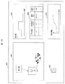
ここで、入出力装置1004が表示する画面の一例を、図16に示す。入出力装置1004が表示する画面a501上には、記憶装置群1002が記憶する送配水系を表示する領域a502、ユーザが入力装置を介して選択した送配水設備の情報を表示する領域a503が表示される。例えば、入力装置としてポインティングデバイスを用意しておき、ユーザが当該入力装置を介して、符号a502で示された設備をクリックすると、計画装置1001は、入出力部1041でその情報を受信する。その後、計画装置1001は、選択された設備の情報を、各記憶装置から参照して表示する。
Here, an example of a screen displayed by the input /
また、図16の表示例では、或る送水管の時間毎の流量をグラフ表示a502している。ここでは、簡単のため、送水管の流量のみを図示しているが、流速など、他のデータをも表示してもよい。また、管だけに限らず、ポンプや配水池、需要家などのデータを表示することもでき、加えて、同時に複数の設備のデータを表示することもできる。 Moreover, in the display example of FIG. 16, the flow rate for every time of a certain water pipe is displayed on the graph a502. Here, for the sake of simplicity, only the flow rate of the water pipe is shown, but other data such as a flow rate may also be displayed. Moreover, not only pipes but also data on pumps, reservoirs, customers, etc. can be displayed, and in addition, data on a plurality of facilities can be displayed at the same time.
また、図中の符号a504は、記憶装置群1002を構成する前記各記憶装置が保存しているテーブルを表示する領域である。一例として、或る浄水場のデータを図示しているが、前記各記憶装置が保存している任意のテーブルを表示できる。加えて、キーボードなどの入力装置が、ユーザによりテーブルの値を変更するよう入力を受けた場合は、記憶装置郡1002は、各々が保存するテーブルの情報を、前記入力に従い修正する。
Reference numeral a504 in the drawing is an area for displaying a table stored in each of the storage devices constituting the
また、符号a505は目的関数の時間毎の累積値を表示する領域であり、a506は計画装置1001の処理を起動するためのボタンである。入力装置は、ユーザによりボタンa506が押下された情報を計画装置1001へ送信し、計画装置1001は、上記図9に示す処理を実行する。
Symbol a505 is an area for displaying the cumulative value of the objective function for each time, and a506 is a button for starting the processing of the
なお、ユーザは、本システムを、送配水設備の更新計画を立案するための意思決定支援としても利用できる。例えば、ユーザが本システムを実行し、計画装置1001が立案した計画を得る。ユーザは、その計画を閲覧することで、消費電力量が最大の設備を特定できる。
The user can also use this system as a decision support for drafting an update plan for water transmission and distribution equipment. For example, the user executes this system and obtains a plan created by the
更に、ユーザは、その情報を高効率機器(例えば、可変速のポンプ)への設備更新を行うための参考情報として利用できる。また、ユーザは設備を追加した場合の消費電力量の変化をシミュレーションすることもできる。例えば、予め浄水場や配水池を追加したデータを記憶した記憶装置1012を用意する。その後に、ユーザは本システムを実行し、上述した配水制御部1011、水運用計画立案部1021、連携部1031により、上述した処理を実行させる。これにより、ユーザは、追加する前後での各設備の変化を知ることができる。
Further, the user can use the information as reference information for updating equipment to a highly efficient device (for example, a variable speed pump). In addition, the user can also simulate a change in power consumption when equipment is added. For example, the memory |
以下、本発明の第二の実施形態(実施例2)について、添付の図面を参照しながら説明する。
本実施例2の水運用および配水制御システムの特徴は、上述した実施例1とは異なり、計画装置1001が消費電力量ではなく、電力料金を最小化するよう、配水計画および水運用計画を立案する点である。
Hereinafter, a second embodiment (Example 2) of the present invention will be described with reference to the accompanying drawings.
The features of the water operation and water distribution control system of the second embodiment are different from the first embodiment described above, and the water distribution plan and the water operation plan are planned so that the
具体的には、計算条件データ記憶装置1032(上記図1を参照)が、消費電力量から電力料金を計算する式の記述方法、及び、そのための変数や定数を記憶している。加えて、配水制御部1011、水運用計画立案部1021、及び、連携部1031は、前述した最適化計算において、目的関数を電力料金とし、これを最小化するよう処理を実行する。
Specifically, the calculation condition data storage device 1032 (see FIG. 1 above) stores an expression description method for calculating a power charge from the power consumption, and variables and constants therefor. In addition, the water
計算条件データ記憶装置1032が記憶する電力料金について、以下に説明する。
一般的に、国や地域、供給家と水道事業者で結ばれる契約形態に応じて、電力料金は異なる。そのため、上記記憶装置1032は、各時間における電力料金を、テーブルの形で記憶する。
The power charges stored in the calculation condition
In general, the electricity rate varies depending on the country, region, and contract type concluded between the supplier and the water utility. Therefore, the
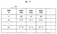
図17は、上記記憶装置1032が記憶するテーブルの一例を示しており、図において、テーブル901の横軸は時間を、縦軸は配水池ID又は浄水場IDを示している。即ち、予め定めた時間枠「t」から「t+1」の間に電力を「1kW」使用する場合にかかる料金を、配水池および浄水場毎に記憶している。なお、時間枠は、例えば、1時間間隔で設定できる。
FIG. 17 shows an example of a table stored in the
計画装置1001が、或る配水池「r_i」の時間枠「t,t+1」における電力料金を参照する場合には、定数「U(t,r_i)」として記述する。同様に、浄水場「w」の場合は、「U(t,w)」と記述する。
When the
次に、配水制御部1011が電力料金を最小化するよう最適化する場合について説明する。なお、上記実施例1との相違点は、目的関数を以下の式19に変更する点である。
Next, the case where the water
更に、水運用計画立案部1021が電力料金を最小化するよう最適化する場合について説明する。上記実施例1との相違点は、目的関数を以下の式20に変更する点である。
Furthermore, the case where the water operation
そして、連携部1031が電力料金を最小化するよう最適化する場合について説明する。上記実施例1との相違点は、目的関数を以下の式21に変更する点である。
A case where the
以下、本発明の第三の実施形態(実施例3)について説明する。
本実施例3と上記実施例1との相違点は、連携部1031が実行する計画修正施設探索処理(図14のステップS421)にある。即ち、本実施例においては、配水計画を修正する配水系統を決定する際に実行する探索において、或る方向への探索終了条件を、予め定めた任意の距離だけ探索することとしている。
The third embodiment (Example 3) of the present invention will be described below.
The difference between the third embodiment and the first embodiment is in the plan correction facility search process (step S421 in FIG. 14) executed by the
実施例1では、その連携部1031が実行する計画修正施設探索処理(図14のステップS421)は、例えば、図15の配水系において、「pn1」から探索を開始し、浄水場「w1」及び「w2」を発見した時点で探索を終了するものとして説明した。
In Example 1, the plan correction facility search process (step S421 in FIG. 14) executed by the
しかしながら、本実施例3においては、連携部1031が、例えば、探索する距離を「pn1」から「w3」までの距離とする。なお、そのような距離は、計算条件データ記憶装置1032が定数として予め記憶しておいてもよいし、計算方法を連携部1031が実行する上記計画修正施設探索処理(図14のステップS421)の手続きとして記憶しておいてもよい。
However, in the third embodiment, for example, the
例えば、送配水系データ記憶装置1012が記憶する管データの距離は、「pn1」から「w3」までの経路上の分を足し合わせることで計算できる。連携部1031は、そのように探索することで、図15における管「p(p4,j1)」、「p(p1,j2)」、「p(r1,p1)」、「p(w1,r1)」、「p(r2,p4)」、「p(p2,r2)」、「p(w1,p2)」、「p(p3,r2)」、「p(w2,p3)」、「p(w2,r3)」、「p(r3,p5)」、「p(p5,j3)」、「p(p6,j4)」、「p(r4,p6)」、「p(p7,r4)」、「p(w3,p7)」、ポンプ「p1」、「p2」、「p3」、「p4」、「p5」、「p6」、「p7」、配水池「r1」、「r2」、「r3」、「r4」、浄水場「w1」、「w2」、「w3」を検出する。
For example, the distance of the pipe data stored in the transmission / distribution system
なお、計画装置1001が実行するその他の処理は、上記実施例1と同一であり、ここではその説明を省略する。
The other processes executed by the
また、本実施例3においては、探索の終了条件を距離として与えたが、これを浄水場や配水池等の配水系設備をある定数だけ発見したら終了する等としてもよい。そのような定数は、予め、上記記憶装置1032に記憶させておけばよい。例えば、図15において、浄水場を3か所発見したら終了するとすれば、前述と同等の設備が発見される。
In the third embodiment, the search termination condition is given as a distance. However, this may be terminated when only a certain number of water distribution system facilities such as a water purification plant and a water reservoir are found. Such a constant may be stored in the
以下、本発明の第四の実施形態(実施例4)について説明する。
本実施例4と上記実施例1との相違点は、計画装置1001が実行する配水制御処理(図11のステップS211)において、二つ以上の候補となる配水計画候補を出力することである。
The fourth embodiment (Example 4) of the present invention will be described below.
The difference between the present Example 4 and the said Example 1 is that the water distribution plan candidate used as two or more candidates is output in the water distribution control process (step S211 of FIG. 11) which the
例えば、計画装置1001が、上記配水制御処理(図11のステップS211)の実行において、最適化問題を遺伝的アルゴリズムなどの解候補を複数生成するアルゴリズムにより解くとする。計画装置1001は、このとき生成した解候補のうち、予め定めた上位「N」件を配水計画候補として出力する。なお、「N」は計算条件データ記憶装置が保存している定数である。また、計画装置1001が、実績値のデータを配水計画候補として用いてもよい。
For example, it is assumed that the
以降、計画装置1001が、水運用計画立案処理および連携処理を、配水計画候補の各々に対して第一の実施例と同様に実行する。但し、計画装置1001が二回以上、上記の配水制御処理(図9のステップS121)を実行する場合、二度目以降の当該処理に関しては、連携処理(図9のステップS161)で出力した「N」件の配水計画候補に対して、それぞれ、上記実施例1と同様に処理を実行し、1つの配水計画候補を出力する。
Thereafter, the
その後、全ての配水計画候補に関して水運用計画立案処理および連携処理が完了した後、計画装置1001は、最終的に目的関数が最小となる配水計画および水運用計画を採用し、入出力装置1004へ送信する。計画装置1001は、そのときの送配水データを記憶装置1012へ記憶する。
Thereafter, after the water operation plan planning process and the cooperation process are completed for all water distribution plan candidates, the
以上、本発明について詳細に説明したが、しかしながら、本発明は上記した実施例に限定されるものではなく、様々な変形例が含まれる。例えば、上記した実施例は本発明を分かりやすく説明するために詳細に説明したものであり、必ずしも説明した全ての構成を備えるものに限定されるものではない。また、ある実施例の構成の一部を他の実施例の構成に置き換えることが可能であり、また、ある実施例の構成に他の実施例の構成を加えることも可能である。また、各実施例の構成の一部について、他の構成の追加・削除・置換をすることが可能である。 The present invention has been described in detail above. However, the present invention is not limited to the above-described embodiments, and various modifications are included. For example, the above-described embodiments have been described in detail for easy understanding of the present invention, and are not necessarily limited to those having all the configurations described. Further, a part of the configuration of one embodiment can be replaced with the configuration of another embodiment, and the configuration of another embodiment can be added to the configuration of one embodiment. Further, it is possible to add, delete, and replace other configurations for a part of the configuration of each embodiment.
また、上記の各構成、機能、処理部、処理手段等は、それらの一部又は全部を、例えば集積回路で設計する等によりハードウェアで実現してもよい。また、上記の各構成、機能等は、プロセッサがそれぞれの機能を実現するプログラムを解釈し、実行することによりソフトウェアで実現してもよい。各機能を実現するプログラム、テーブル、ファイル等の情報は、メモリや、ハードディスク、SSD(Solid State Drive)等の記憶装置、または、ICカード、SDカード、DVD等の記憶媒体に置くことができる。 Each of the above-described configurations, functions, processing units, processing means, and the like may be realized by hardware by designing a part or all of them with, for example, an integrated circuit. Each of the above-described configurations, functions, and the like may be realized by software by interpreting and executing a program that realizes each function by the processor. Information such as programs, tables, and files that realize each function can be stored in a storage device such as a memory, a hard disk, or an SSD (Solid State Drive), or a storage medium such as an IC card, an SD card, or a DVD.
また、制御線や情報線は説明上必要と考えられるものを示しており、製品上必ずしも全ての制御線や情報線を示しているとは限らない。実際には殆ど全ての構成が相互に接続されていると考えてもよい。 Further, the control lines and information lines indicate what is considered necessary for the explanation, and not all the control lines and information lines on the product are necessarily shown. Actually, it may be considered that almost all the components are connected to each other.
1000…水運用および配水制御システム、1001…計画装置、1011…配水制御部、1021…水運用計画立案部、1031…連携部、1041…入出力部、1002…記憶装置群、1012…送配水系データ記憶装置、1022…需要家データ記憶装置、1032…計算条件データ記憶装置、1003…送配水系、1013…配水所、1113…配水所制御装置、1213…配水池、1313…配水ポンプ、1023…配水管網、
1123…配水管、1223…需要家、1323…配水管分岐点、1033…送水管、
1043…送水管分岐点、1053…浄水場、1063…配水池、1073…送水ポンプ、1004…入出力装置
DESCRIPTION OF
1123: Distribution pipe, 1223 ... Consumer, 1323 ... Distribution pipe branch point, 1033 ... Transmission pipe,
1043 ... Water pipe branch point, 1053 ... Water purification plant, 1063 ... Water distribution reservoir, 1073 ... Water pump, 1004 ... I / O device
Claims (11)
前記送配水系を制御する計画装置と、
前記計画装置に接続された記憶装置群と、
前記計画装置との間で信号を送受信する入出力装置とから成る水運用および配水制御システムであって、
前記計画装置は、
配水所から需要家までの配水系において、ポンプの吐出圧、及び、配水所からの配水量の計画である配水計画を立案する配水制御部と、
取水源から配水所までの送水系における管路内の流量の計画である水運用計画を立案する水運用計画立案部と、
前記水運用計画立案部及び前記配水制御部の立案結果を修正する連携部と、
を備えており、
前記計画装置は、前記配水制御部、前記水運用計画立案部、及び、前記連携部の処理を反復して実行することで、目的関数が最小のポンプの運転スケジュールを定めるための送配水計画を立案する処理を実行することを特徴とする水運用および配水制御システム。 Transmission and distribution system from intake to customer,
A planning device for controlling the transmission and distribution system;
A storage device group connected to the planning device;
A water operation and distribution control system comprising an input / output device that transmits and receives signals to and from the planning device,
The planning device
In the water distribution system from the water distribution station to the customer, a water distribution control unit that formulates a water distribution plan that is a plan of the discharge pressure of the pump and the water distribution amount from the water distribution station,
A water operation plan drafting unit that formulates a water operation plan that is a plan of the flow rate in the pipeline in the water transmission system from the intake source to the water distribution station;
A cooperation unit that corrects the planning results of the water operation plan planning unit and the water distribution control unit;
With
The planning device repeats and executes the processing of the water distribution control unit, the water operation plan planning unit, and the linkage unit, thereby performing a water transmission / distribution plan for determining an operation schedule of a pump having a minimum objective function. A water operation and distribution control system characterized by executing a planning process.
前記記憶装置群は、送水及び配水に係る送配水設備のデータを記憶した送配水系データ記憶装置と、
需要家の位置及び需要量から成る需要量データを記憶した需要家データ記憶装置と、
前記水運用計画立案部及び前記配水計画立案部の実行にあたり利用する計算条件データおよび制約データを記憶した計算条件記憶装置と、
を備えていることを特徴とする水運用および配水制御システム。 In the water operation and water distribution control system according to claim 1,
The storage device group includes a transmission / distribution system data storage device that stores data of water transmission / distribution equipment related to water transmission and distribution, and
A customer data storage device storing demand data consisting of a customer's position and demand; and
A calculation condition storage device that stores calculation condition data and constraint data to be used in the execution of the water operation plan drafting unit and the water distribution plan drafting unit;
A water operation and distribution control system characterized by comprising:
前記送配水設備は、浄水場、配水所、浄水場及び/又は配水所に設置された送水ポンプ及び/又は配水ポンプ、送水管分岐点、送水管、配水管分岐点、及び/又は、配水管を含んでおり、
前記送配水系データ記憶装置が、前記浄水場、前記配水所、浄水場及び/又は配水所に設置された前記送水ポンプ、前記送水管分岐点、及び/又は、前記送水管のデータから成る送水系データと、そして、前記配水所、配水所に設置された前記配水ポンプと、前記配水管分岐点と、前記配水管と、配水管に接続された前記需要家とから成る配水系データとを記憶しており、
前記計算条件データ記憶装置が、前記送水系データから水運用計画立案のための最適化問題を定式化するための制約および目的関数の記述方法と、前記配水系データから配水計画立案およびと出圧決定のための最適化問題を定式化するための制約および目的関数の記述方法と、前記送配水設備の消費電力量を計算するためのモデルと、
前記送配水設備を動作させるための制約とを記憶しており、そして、
前記需要家データ記憶装置が、一日の需要量パターンを記憶していることを特徴とする水運用および配水制御システム。 In the water operation and distribution control system according to claim 2,
The water supply and distribution equipment includes a water purification plant, a water distribution plant, a water purification plant and / or a water supply pump and / or a water distribution pump, a water supply pipe branch point, a water pipe, a water pipe branch point, and / or a water pipe. Contains
The water transmission / distribution system data storage device comprises data of the water purification plant, the water distribution plant, the water purification plant and / or the water supply pump installed at the water distribution plant, the water pipe branch point, and / or the data of the water pipe. Water system data, and water distribution system data comprising the water distribution station, the water distribution pump installed in the water distribution station, the water distribution pipe branch point, the water distribution pipe, and the consumer connected to the water distribution pipe. Remember,
The calculation condition data storage device includes a constraint and objective function description method for formulating an optimization problem for water operation planning from the water transmission system data, water distribution planning and output pressure from the water distribution data A constraint and objective function description method for formulating an optimization problem for determination, a model for calculating the power consumption of the transmission and distribution equipment,
Remembers constraints for operating the water distribution and distribution facility; and
A water operation and distribution control system, wherein the customer data storage device stores a daily demand pattern.
前記水運用計画とは、前記配水所が、予め定められた配水量の配水を実現するために必要な配水池の水位を満足するように、前記取水源から前記配水所までの前記送水系における管路の流量を定めた計画であり、
前記配水計画とは、前記配水系において前記計算条件データ記憶装置に記憶された制約データを満足するように前記配水所からの配水量を定めた計画であって、
前記送配水計画とは、前記送配水系全体での管路の流量を定めた計画であって、
前記演算装置が、
(1)前記配水制御部が、前記配水系データ及び前記制約データを入力として数理計画問題を定式化して、前記問題を解くことで前記吐出圧及び前記配水計画を決定する配水制御処理と、
(2)前記水運用計画立案部が、前記配水計画により定められた配水所からの配水量および送水系データを入力として数理計画問題を定式化して、前記問題を解くことで前記水運用計画を立案する水運用計画立案処理と、
(3)前記連携部が、前記送配水計画を、送配水計画を修正する範囲を探索により特定する探索処理と、前記特定された配水所の配水量及び前記配水所へ送水している浄水場との間で管路の流量を、前記制約データに違反しないよう、かつ、前記送水系及び前記配水系の全体で前記所定の目的が改善されるよう修正する管路流量最適化処理とから成る連携処理とを実行し、
もって、前記計算条件データに記載された回数又は消費電力量の削減が不可能となるまで順番に反復することで、前記配水計画および前記水運用計画が、目的関数を最小化するようポンプの運転スケジュールを定めるように修正することを特徴とする水運用および配水制御システム。 In the water operation and distribution control system according to claim 3,
The water operation plan means that in the water transmission system from the water intake source to the water distribution station, the water distribution station satisfies the water level of the water distribution reservoir necessary for realizing the water distribution of a predetermined water distribution amount. It is a plan that determines the flow rate of the pipeline,
The water distribution plan is a plan in which the amount of water distribution from the water distribution station is determined so as to satisfy the constraint data stored in the calculation condition data storage device in the water distribution system,
The water transmission and distribution plan is a plan that determines the flow rate of the pipeline in the entire transmission and distribution system,
The arithmetic unit is
(1) The water distribution control unit formulates a mathematical planning problem using the water distribution system data and the constraint data as inputs, and determines the discharge pressure and the water distribution plan by solving the problem;
(2) The water operation plan drafting section formulates a mathematical planning problem using the amount of water distribution and water transmission system data determined by the water distribution plan as input, and solves the problem to formulate the water operation plan. A water management plan planning process to be planned;
(3) The water treatment plant in which the cooperation unit specifies the transmission / distribution plan by searching for a range for correcting the transmission / distribution plan, and the amount of water distribution of the identified water distribution plant and the water distribution plant. A flow rate optimization process for correcting the flow rate of the pipeline so as not to violate the constraint data and to improve the predetermined purpose in the entire water supply system and the water distribution system. Execute cooperation processing,
Accordingly, by repeating the number of times described in the calculation condition data or the power consumption amount in order until it becomes impossible to reduce the power consumption amount, the water distribution plan and the water operation plan are operated so that the objective function is minimized. A water operation and distribution control system characterized by amendments to establish a schedule.
前記連携処理における探索処理が、配水の電力コストの比が配水所間で最も高い配水管網を探索の始点とすることを特徴とする水運用および配水制御システム。 In the water operation and distribution control system according to claim 4,
The water operation and distribution control system characterized in that the search processing in the cooperative processing uses a distribution pipe network having the highest ratio of power cost of water distribution among water distribution stations as a search starting point.
前記連携処理における探索処理が、探索の始点から送配水系を任意の距離だけ探索する間に発見した送配水設備を、送配水計画の修正範囲とすることを特徴とする水運用および配水制御システム。 In the water operation and distribution control system according to claim 4,
The water operation and distribution control system characterized in that the search processing in the cooperative processing is a correction range of the transmission / distribution plan, wherein the distribution / distribution facility discovered while searching for an arbitrary distance from the starting point of the search to the transmission / distribution system .
前記目的関数が、消費電力量または電力料金であることを特徴とする水運用および配水制御システム。 In the water operation and distribution control system according to claim 4,
A water operation and water distribution control system, wherein the objective function is a power consumption amount or a power charge.
前記システムを稼動した際の実績値を記憶する実績値記憶装置を備えることを特徴とする水運用および配水制御システム。 In the water operation and distribution control system according to claim 4, further comprising:
A water operation and water distribution control system comprising a record value storage device for storing record values when the system is operated.
前記配水制御部が、前記配水制御処理において、前記配水系データおよび前記制約データを入力として数理計画問題を定式化して、前記問題を解き二つ以上の配水計画の候補を出力する配水制御処理を行うことを特徴とする水運用および配水制御システム。 In the water operation and distribution control system according to claim 4,
In the water distribution control process, the water distribution control unit formulates a mathematical planning problem with the water distribution system data and the constraint data as inputs, solves the problem, and outputs two or more water distribution plan candidates. Water operation and distribution control system characterized by performing.
前記送配水設備のデータと、
前記需要家データと、
前記演算装置が計算した消費電力量のデータと、
を受信し、当該受信した前記データを前記表示装置に表示するための処理を実行することを特徴とする水運用および配水制御システム。 The water operation and water distribution control system according to claim 1, further comprising a display device, the display device from the planning device,
Data of the water transmission and distribution equipment;
The customer data;
Data of power consumption calculated by the arithmetic unit;
And a process for displaying the received data on the display device is executed.
前記計画装置は、
ユーザが入力装置を介して送信した起動命令を受信して処理を開始する機能と、
前記計画装置の前記配水制御処理と、前記水運用計画立案処理と、前記連携処理の実行前にユーザの入力を受けて前記記憶装置群が記憶するデータを修正する機能と、
を備えていることを特徴とする水運用および配水制御システム。 In the water operation and distribution control system according to claim 4,
The planning device
A function of receiving a start command transmitted by a user via an input device and starting processing;
A function of correcting the data stored in the storage device group in response to a user input before execution of the water distribution control processing, the water operation plan planning processing, and the cooperation processing of the planning device;
A water operation and distribution control system characterized by comprising:
Priority Applications (1)
| Application Number | Priority Date | Filing Date | Title |
|---|---|---|---|
| JP2013255733A JP6174474B2 (en) | 2013-12-11 | 2013-12-11 | Water operation and distribution control system |
Applications Claiming Priority (1)
| Application Number | Priority Date | Filing Date | Title |
|---|---|---|---|
| JP2013255733A JP6174474B2 (en) | 2013-12-11 | 2013-12-11 | Water operation and distribution control system |
Publications (3)
| Publication Number | Publication Date |
|---|---|
| JP2015114804A true JP2015114804A (en) | 2015-06-22 |
| JP2015114804A5 JP2015114804A5 (en) | 2016-09-23 |
| JP6174474B2 JP6174474B2 (en) | 2017-08-02 |
Family
ID=53528567
Family Applications (1)
| Application Number | Title | Priority Date | Filing Date |
|---|---|---|---|
| JP2013255733A Active JP6174474B2 (en) | 2013-12-11 | 2013-12-11 | Water operation and distribution control system |
Country Status (1)
| Country | Link |
|---|---|
| JP (1) | JP6174474B2 (en) |
Cited By (6)
| Publication number | Priority date | Publication date | Assignee | Title |
|---|---|---|---|---|
| JP2017182305A (en) * | 2016-03-29 | 2017-10-05 | 株式会社日立製作所 | System and method for planning water utilization |
| JP2019109583A (en) * | 2017-12-15 | 2019-07-04 | 株式会社日立製作所 | Water balance visualization system and water balance visualization method |
| KR101993449B1 (en) * | 2019-01-17 | 2019-09-30 | 주식회사 아이씨티솔루션스 | Energy optimization system using measuring and controling of water treatment facility |
| KR102644359B1 (en) * | 2023-05-22 | 2024-03-07 | 주식회사 비즈데이터 | Reservoir linked water pump control method and apparatus |
| JP7448082B1 (en) | 2023-10-31 | 2024-03-12 | 株式会社Ihi | Water distribution support system |
| JP2024072175A (en) * | 2022-11-15 | 2024-05-27 | 株式会社日立製作所 | Water operation planning support device and water operation planning support method |
Citations (6)
| Publication number | Priority date | Publication date | Assignee | Title |
|---|---|---|---|---|
| JP2001022437A (en) * | 1999-07-13 | 2001-01-26 | Toshiba Corp | Computer-readable recording medium recording plant control device and plant control program |
| JP2006048212A (en) * | 2004-08-02 | 2006-02-16 | Toshiba Corp | Operation plan creation apparatus and method for wide area water operation system |
| US20070130093A1 (en) * | 2005-12-07 | 2007-06-07 | Alireza Haji-Valizadeh | Utility management system and method |
| JP2012197629A (en) * | 2011-03-22 | 2012-10-18 | Hitachi Ltd | Water supply central monitoring control device, water supply monitoring control system, and water supply monitoring control program |
| JP2013064245A (en) * | 2011-09-16 | 2013-04-11 | Hitachi Ltd | Water intake/conveyance operation controller |
| JP2013227826A (en) * | 2012-04-27 | 2013-11-07 | Hitachi Ltd | Water distribution application control device |
-
2013
- 2013-12-11 JP JP2013255733A patent/JP6174474B2/en active Active
Patent Citations (6)
| Publication number | Priority date | Publication date | Assignee | Title |
|---|---|---|---|---|
| JP2001022437A (en) * | 1999-07-13 | 2001-01-26 | Toshiba Corp | Computer-readable recording medium recording plant control device and plant control program |
| JP2006048212A (en) * | 2004-08-02 | 2006-02-16 | Toshiba Corp | Operation plan creation apparatus and method for wide area water operation system |
| US20070130093A1 (en) * | 2005-12-07 | 2007-06-07 | Alireza Haji-Valizadeh | Utility management system and method |
| JP2012197629A (en) * | 2011-03-22 | 2012-10-18 | Hitachi Ltd | Water supply central monitoring control device, water supply monitoring control system, and water supply monitoring control program |
| JP2013064245A (en) * | 2011-09-16 | 2013-04-11 | Hitachi Ltd | Water intake/conveyance operation controller |
| JP2013227826A (en) * | 2012-04-27 | 2013-11-07 | Hitachi Ltd | Water distribution application control device |
Cited By (7)
| Publication number | Priority date | Publication date | Assignee | Title |
|---|---|---|---|---|
| JP2017182305A (en) * | 2016-03-29 | 2017-10-05 | 株式会社日立製作所 | System and method for planning water utilization |
| JP2019109583A (en) * | 2017-12-15 | 2019-07-04 | 株式会社日立製作所 | Water balance visualization system and water balance visualization method |
| KR101993449B1 (en) * | 2019-01-17 | 2019-09-30 | 주식회사 아이씨티솔루션스 | Energy optimization system using measuring and controling of water treatment facility |
| JP2024072175A (en) * | 2022-11-15 | 2024-05-27 | 株式会社日立製作所 | Water operation planning support device and water operation planning support method |
| KR102644359B1 (en) * | 2023-05-22 | 2024-03-07 | 주식회사 비즈데이터 | Reservoir linked water pump control method and apparatus |
| JP7448082B1 (en) | 2023-10-31 | 2024-03-12 | 株式会社Ihi | Water distribution support system |
| JP2025075501A (en) * | 2023-10-31 | 2025-05-15 | 株式会社Ihi | Water Distribution Support System |
Also Published As
| Publication number | Publication date |
|---|---|
| JP6174474B2 (en) | 2017-08-02 |
Similar Documents
| Publication | Publication Date | Title |
|---|---|---|
| JP6174474B2 (en) | Water operation and distribution control system | |
| Salomons et al. | Practical real-time optimization for energy efficient water distribution systems operation | |
| Dorfner | Open source modelling and optimisation of energy infrastructure at urban scale | |
| Odan et al. | Real-time multiobjective optimization of operation of water supply systems | |
| JP5746940B2 (en) | Intake water operation control device | |
| CN104424512B (en) | Operation planning decision-making technique and operation planning decision system | |
| Salomons et al. | A practical optimization scheme for real-time operation of water distribution systems | |
| KR20160043845A (en) | System and method for managing water in water pipe network | |
| NO20140362A1 (en) | System and procedure for optimizing operation of a water network | |
| WO2012127977A1 (en) | Central waterworks monitoring and controlling device, waterworks monitoring and controlling system, and waterworks monitoring and controlling program | |
| Skworcow et al. | Optimisation of pump and valve schedules in complex large-scale water distribution systems using GAMS modelling language | |
| Dhaliwal et al. | Modified binary differential evolution algorithm to solve unit commitment problem | |
| Pecci et al. | Model reduction and outer approximation for optimizing the placement of control valves in complex water networks | |
| CN117993128A (en) | A natural gas pipeline network path optimization method and device | |
| WO2011127260A1 (en) | Computer-implemented method for managing commodity consumption within an industrial production facility | |
| JP2015156770A (en) | Operation plan support program, operation plan support method, and operation plan support device | |
| Weißenberger et al. | Model driven engineering of manufacturing execution systems using a formal specification | |
| JP6881311B2 (en) | Water distribution operation system, water distribution operation method, and recording medium | |
| García-Sánchez et al. | Combining simulation and tabu search for oil-derivatives pipeline scheduling | |
| CN114626173A (en) | Multi-period natural gas pipeline network conveying capacity improvement design method and device | |
| Melkumov et al. | A problem of finding an optimal structure of heat supply networks | |
| Asefa | Innovative systems-based decision support: Tales for the real world | |
| Yuan et al. | Power‐based transmission constrained unit commitment formulation with energy‐based reserve | |
| Vassiljev et al. | Decreasing leakage and operational cost for BBLAWN | |
| KR20150124357A (en) | Apparatus and method for analyzing fluid stream in pipe network based gis |
Legal Events
| Date | Code | Title | Description |
|---|---|---|---|
| A521 | Request for written amendment filed |
Free format text: JAPANESE INTERMEDIATE CODE: A523 Effective date: 20160802 |
|
| A621 | Written request for application examination |
Free format text: JAPANESE INTERMEDIATE CODE: A621 Effective date: 20160802 |
|
| A977 | Report on retrieval |
Free format text: JAPANESE INTERMEDIATE CODE: A971007 Effective date: 20170412 |
|
| A131 | Notification of reasons for refusal |
Free format text: JAPANESE INTERMEDIATE CODE: A131 Effective date: 20170418 |
|
| A521 | Request for written amendment filed |
Free format text: JAPANESE INTERMEDIATE CODE: A523 Effective date: 20170605 |
|
| TRDD | Decision of grant or rejection written | ||
| A01 | Written decision to grant a patent or to grant a registration (utility model) |
Free format text: JAPANESE INTERMEDIATE CODE: A01 Effective date: 20170620 |
|
| A61 | First payment of annual fees (during grant procedure) |
Free format text: JAPANESE INTERMEDIATE CODE: A61 Effective date: 20170706 |
|
| R150 | Certificate of patent or registration of utility model |
Ref document number: 6174474 Country of ref document: JP Free format text: JAPANESE INTERMEDIATE CODE: R150 |