JP2015120102A - Flue gas desulfurizer and flue gas desulfurization method - Google Patents
Flue gas desulfurizer and flue gas desulfurization method Download PDFInfo
- Publication number
- JP2015120102A JP2015120102A JP2013264321A JP2013264321A JP2015120102A JP 2015120102 A JP2015120102 A JP 2015120102A JP 2013264321 A JP2013264321 A JP 2013264321A JP 2013264321 A JP2013264321 A JP 2013264321A JP 2015120102 A JP2015120102 A JP 2015120102A
- Authority
- JP
- Japan
- Prior art keywords
- liquid
- wall
- absorption
- flue gas
- spray
- Prior art date
- Legal status (The legal status is an assumption and is not a legal conclusion. Google has not performed a legal analysis and makes no representation as to the accuracy of the status listed.)
- Pending
Links
- 238000006477 desulfuration reaction Methods 0.000 title claims abstract description 62
- 230000023556 desulfurization Effects 0.000 title claims abstract description 62
- UGFAIRIUMAVXCW-UHFFFAOYSA-N Carbon monoxide Chemical compound [O+]#[C-] UGFAIRIUMAVXCW-UHFFFAOYSA-N 0.000 title claims abstract description 43
- 239000003546 flue gas Substances 0.000 title claims abstract description 43
- 238000000034 method Methods 0.000 title claims abstract description 17
- 239000007788 liquid Substances 0.000 claims abstract description 224
- 238000010521 absorption reaction Methods 0.000 claims abstract description 152
- 239000007921 spray Substances 0.000 claims abstract description 113
- 239000002002 slurry Substances 0.000 claims abstract description 91
- 235000019738 Limestone Nutrition 0.000 claims abstract description 27
- 239000006028 limestone Substances 0.000 claims abstract description 27
- 229910052815 sulfur oxide Inorganic materials 0.000 claims abstract description 12
- XTQHKBHJIVJGKJ-UHFFFAOYSA-N sulfur monoxide Chemical class S=O XTQHKBHJIVJGKJ-UHFFFAOYSA-N 0.000 claims abstract description 9
- 235000008733 Citrus aurantifolia Nutrition 0.000 claims abstract description 8
- 235000011941 Tilia x europaea Nutrition 0.000 claims abstract description 8
- 239000004571 lime Substances 0.000 claims abstract description 8
- 238000005507 spraying Methods 0.000 claims abstract description 5
- 239000007789 gas Substances 0.000 claims description 30
- 238000002485 combustion reaction Methods 0.000 claims description 7
- 239000000779 smoke Substances 0.000 claims description 3
- 230000003009 desulfurizing effect Effects 0.000 claims 1
- 239000010440 gypsum Substances 0.000 abstract description 13
- 229910052602 gypsum Inorganic materials 0.000 abstract description 13
- 238000005299 abrasion Methods 0.000 abstract description 11
- 230000001629 suppression Effects 0.000 abstract description 6
- 230000003247 decreasing effect Effects 0.000 abstract 1
- 230000002745 absorbent Effects 0.000 description 67
- 239000002250 absorbent Substances 0.000 description 67
- 239000000463 material Substances 0.000 description 21
- 229910004298 SiO 2 Inorganic materials 0.000 description 9
- 229910018072 Al 2 O 3 Inorganic materials 0.000 description 8
- 230000007423 decrease Effects 0.000 description 8
- 238000002347 injection Methods 0.000 description 7
- 239000007924 injection Substances 0.000 description 7
- 230000002265 prevention Effects 0.000 description 7
- VTYYLEPIZMXCLO-UHFFFAOYSA-L Calcium carbonate Chemical compound [Ca+2].[O-]C([O-])=O VTYYLEPIZMXCLO-UHFFFAOYSA-L 0.000 description 6
- 238000006243 chemical reaction Methods 0.000 description 4
- 238000005259 measurement Methods 0.000 description 4
- 229910001220 stainless steel Inorganic materials 0.000 description 4
- 239000010935 stainless steel Substances 0.000 description 4
- 229910000019 calcium carbonate Inorganic materials 0.000 description 3
- 230000000694 effects Effects 0.000 description 3
- 239000002245 particle Substances 0.000 description 3
- 239000004743 Polypropylene Substances 0.000 description 2
- VYPSYNLAJGMNEJ-UHFFFAOYSA-N Silicium dioxide Chemical compound O=[Si]=O VYPSYNLAJGMNEJ-UHFFFAOYSA-N 0.000 description 2
- QVGXLLKOCUKJST-UHFFFAOYSA-N atomic oxygen Chemical compound [O] QVGXLLKOCUKJST-UHFFFAOYSA-N 0.000 description 2
- 239000011575 calcium Substances 0.000 description 2
- 238000010276 construction Methods 0.000 description 2
- 238000010586 diagram Methods 0.000 description 2
- 238000010790 dilution Methods 0.000 description 2
- 239000012895 dilution Substances 0.000 description 2
- 238000000605 extraction Methods 0.000 description 2
- 239000008235 industrial water Substances 0.000 description 2
- 238000009434 installation Methods 0.000 description 2
- 238000012423 maintenance Methods 0.000 description 2
- 239000003921 oil Substances 0.000 description 2
- 230000001590 oxidative effect Effects 0.000 description 2
- 229910052760 oxygen Inorganic materials 0.000 description 2
- 239000001301 oxygen Substances 0.000 description 2
- 230000002093 peripheral effect Effects 0.000 description 2
- 229920001155 polypropylene Polymers 0.000 description 2
- 238000011084 recovery Methods 0.000 description 2
- 239000013535 sea water Substances 0.000 description 2
- 239000004071 soot Substances 0.000 description 2
- 230000003746 surface roughness Effects 0.000 description 2
- 239000002699 waste material Substances 0.000 description 2
- 239000006096 absorbing agent Substances 0.000 description 1
- 239000002253 acid Substances 0.000 description 1
- 238000003915 air pollution Methods 0.000 description 1
- 230000002542 deteriorative effect Effects 0.000 description 1
- TXKMVPPZCYKFAC-UHFFFAOYSA-N disulfur monoxide Inorganic materials O=S=S TXKMVPPZCYKFAC-UHFFFAOYSA-N 0.000 description 1
- 239000000428 dust Substances 0.000 description 1
- 239000002803 fossil fuel Substances 0.000 description 1
- 230000005484 gravity Effects 0.000 description 1
- 239000012535 impurity Substances 0.000 description 1
- 230000000116 mitigating effect Effects 0.000 description 1
- TWNQGVIAIRXVLR-UHFFFAOYSA-N oxo(oxoalumanyloxy)alumane Chemical compound O=[Al]O[Al]=O TWNQGVIAIRXVLR-UHFFFAOYSA-N 0.000 description 1
- -1 polypropylene Polymers 0.000 description 1
- 239000011347 resin Substances 0.000 description 1
- 229920005989 resin Polymers 0.000 description 1
- HBMJWWWQQXIZIP-UHFFFAOYSA-N silicon carbide Chemical compound [Si+]#[C-] HBMJWWWQQXIZIP-UHFFFAOYSA-N 0.000 description 1
- 235000012239 silicon dioxide Nutrition 0.000 description 1
- 239000000377 silicon dioxide Substances 0.000 description 1
- 239000007787 solid Substances 0.000 description 1
- 239000011343 solid material Substances 0.000 description 1
- 239000000243 solution Substances 0.000 description 1
Images





Landscapes
- Treating Waste Gases (AREA)
- Gas Separation By Absorption (AREA)
Abstract
Description
本発明は、脱硫吸収液として用いる石灰石(炭酸カルシウム)又は石灰を含むスラリ状の吸収液中にSiO2、Al2O3などの摩耗成分が含まれる石灰石−石膏法排煙脱硫装置及び排煙脱硫方法に係わり、特に脱硫吸収塔における内壁の耐摩耗性向上に好適な排煙脱硫装置及び排煙脱硫方法に関する。 The present invention relates to a limestone-gypsum flue gas desulfurization apparatus and flue gas in which wear components such as SiO 2 and Al 2 O 3 are contained in a limestone (calcium carbonate) used as a desulfurization absorbent or a slurry-like absorbent containing lime. The present invention relates to a desulfurization method, and more particularly, to a flue gas desulfurization apparatus and a flue gas desulfurization method suitable for improving wear resistance of an inner wall in a desulfurization absorption tower.
火力発電所等においては、大気汚染防止のため、化石燃料の燃焼に伴い発生する排ガス中の硫黄酸化物(SOx、主にSO2)の除去装置として、石灰石中に含まれる炭酸カルシウム(CaCO3)を硫黄酸化物の吸収剤として用いる石灰石−石膏法排煙脱硫装置が広く実用化されている。図11には、従来技術の排煙脱硫装置における吸収塔1(側面図)を示し、図12には吸収塔の吸収液配管部分の平面図(一部)を示す。また、図13には、図11の内壁近傍のスプレ部4の拡大図を示す。
In thermal power plants and the like, calcium carbonate (CaCO 3 ) contained in limestone is used as a device for removing sulfur oxides (SOx, mainly SO 2 ) in exhaust gas generated by the combustion of fossil fuels in order to prevent air pollution. Limestone-gypsum flue gas desulfurization apparatus using) as a sulfur oxide absorbent has been widely put into practical use. FIG. 11 shows an absorption tower 1 (side view) in a conventional flue gas desulfurization apparatus, and FIG. 12 shows a plan view (part) of an absorption liquid piping portion of the absorption tower. FIG. 13 shows an enlarged view of the
火力発電所や工場等に設置されるボイラ等の燃焼装置から排出される硫黄酸化物を含む排ガスは、図示していない脱硫ファンにより入口ダクト12から矢印X方向(ほぼ水平方向)に流れて吸収塔1に導入された後、上昇し、出口ダクト13から矢印Y方向に排出される。この間、石灰石又は石灰を含むスラリなどの吸収剤を含んだ吸収液が吸収液配管2に取り付けられた複数のスプレノズル3から噴霧される。噴霧された吸収液は、一旦吸収塔1の底部の循環タンク6に溜まり、酸化用撹拌機7によって撹拌されながら、図示しない空気供給管から供給される空気中の酸素により酸化され、石膏を生成する。循環タンク6にあるスラリ状の吸収液の一部は、吸収液循環配管8を経由して、吸収塔1内の上部の吸収液配管2に供給され、一部は図示しない吸収液抜き出し管より図示しない廃液処理・石膏回収系へと送られる。
Exhaust gas containing sulfur oxides discharged from a combustion apparatus such as a boiler installed in a thermal power plant or factory flows through the
脱硫吸収液として用いられる石灰石スラリ(以下、吸収液スラリという)は、吸収液配管2を通じ、吸収塔1内に一定間隔で設置されているスプレノズル3から一定角度で噴射され、排ガスとの気液接触により、下記(1)〜(4)で示す脱硫反応が生じる。
SO2+H2O→H2SO3(1)
2H2SO3+CaCO3→Ca(HSO3) 2+H2O+CO2 (2)
Ca(HSO3) 2+O2+2H2O→CaSO4・2H2O+H2SO4 (3)
H2SO4+CaCO3+H2O→CaSO4・2H2O+CO2 (4)
スプレノズル3から噴射される吸収液スラリ中には、脱硫反応に寄与する成分であるCaCO3以外に、脱硫反応により生じる石膏、石灰石中の不純物である二酸化ケイ素(SiO2)や酸化アルミニウム(Al2O3)などが含まれている。これらSiO2、Al2O3は硬度が高く、スプレノズル3から噴射される吸収液が衝突する吸収塔の内壁が摩耗する主要因となる。
Limestone slurry (hereinafter referred to as absorption liquid slurry) used as a desulfurization absorption liquid is injected through the
SO 2 + H 2 O → H 2 SO 3 (1)
2H 2 SO 3 + CaCO 3 → Ca (HSO 3 ) 2 + H 2 O + CO 2 (2)
Ca (HSO 3 ) 2 + O 2 + 2H 2 O → CaSO 4 .2H 2 O + H 2 SO 4 (3)
H 2 SO 4 + CaCO 3 + H 2 O → CaSO 4 .2H 2 O + CO 2 (4)
In the absorbent slurry sprayed from the spray nozzle 3, in addition to CaCO 3 which is a component contributing to the desulfurization reaction, gypsum generated by the desulfurization reaction, impurities such as silicon dioxide (SiO 2 ) and aluminum oxide (Al 2 ) in the limestone. O 3 ) and the like are included. These SiO 2 and Al 2 O 3 have high hardness, and become the main factor that the inner wall of the absorption tower where the absorbing liquid sprayed from the
図12に示す例では、複数の吸収液配管2が吸収塔1内に同一水平面上に並列配置されており、各吸収液配管2の両端部に設けられたスプレノズル3aが他のスプレノズル3bに比べて内壁に近接しているため、これらのスプレノズル3aからの噴霧液は、他のスプレノズル3bからの噴霧液に比べて内壁への衝突速度が非常に大きいと言える。従って、内壁に近接するスプレノズル3aによる摩耗の対策を講ずることが摩耗の大幅な低減に有用である。
In the example shown in FIG. 12, a plurality of absorbent
一般に、日本国内において使用される排煙脱硫装置では、スラリ中に含まれるSiO2、Al2O3などの摩耗成分が合計0.5%(質量%、以下同じ)程度であり、様々な摩耗対策が取られている。 In general, in flue gas desulfurization equipment used in Japan, the total amount of wear components such as SiO 2 and Al 2 O 3 contained in the slurry is about 0.5% (mass%, the same shall apply hereinafter). Measures are taken.
図14には、従来技術による摩耗抑制法の例を示す。この例では、図13に示す場合と比べて、内壁に近接するスプレノズル3aを傾けて設置し、内壁面への吸収液スラリ流の衝突角度をθ1からθ2(θ2<θ1)に小さくすることで摩耗を抑制している。これは、摩耗速度が吸収液スラリ流の壁面材料に対する衝突角度に依存しており、脱硫塔の内壁に主に用いられるステンレス鋼では、衝突角度が小さい方が、摩耗速度が抑制されることに基づくことによる。また、耐摩耗性の高いライニング施工も実施されており、摩耗による損傷の防止を図っている。 In FIG. 14, the example of the abrasion suppression method by a prior art is shown. In this example, compared to the case shown in FIG. 13, the spray nozzle 3a close to the inner wall is inclined and the collision angle of the absorbent slurry flow on the inner wall is changed from θ 1 to θ 2 (θ 2 <θ 1 ). Wear is suppressed by making it small. This is because the wear rate depends on the collision angle of the absorbent slurry flow against the wall material, and in stainless steel mainly used for the inner wall of the desulfurization tower, the wear rate is suppressed when the collision angle is smaller. By based on. In addition, lining construction with high wear resistance is also carried out to prevent damage due to wear.
例えば、下記特許文献1には、スプレノズルの設置間隔をスプレ有効範囲と等しくして噴射される吸収液の拡がり角度を通常の90〜100度から50〜60度に小さくすることで、脱硫塔内壁への衝突角度を小さくして、吸収塔壁面に衝突する吸収液の量が多くならないようにした方法が開示されている。
For example, in
また、下記特許文献2には、吸収塔の側壁内面全周にガス抜け防止材を設置して、ガス抜け防止材の周方向に沿って不連続に堰を設けた排煙脱硫装置の構成が開示されている。ガス抜け防止材により吸収塔の側壁を伝わってショートパスする排ガスを吸収塔の中心方向に向けることで、排ガスの偏流を防止すると共に、ガス抜け防止材の内周端部に生じる液膜が堰を設けていない部分に流れるため、液膜の形成を妨げて圧力損失の上昇を抑制することができる。
近年、排煙脱硫装置の需要が増加している東南アジア地域では、採掘される石灰石の純度が低く、石灰石中のSiO2、Al2O3などの摩耗成分濃度が25%のものが主流である。吸収液スラリでは、希釈によりその濃度は減少するが、摩耗成分濃度は5%前後となるため、従来の日本国内の火力発電所のプラントと比較して脱硫塔内壁の摩耗速度が大幅に増加すると予想されている。 In Southeast Asia, where demand for flue gas desulfurization equipment is increasing in recent years, the purity of mined limestone is low, and the concentration of wear components such as SiO 2 and Al 2 O 3 in limestone is 25%. . In the absorbent slurry, the concentration decreases due to dilution, but the wear component concentration is around 5%. Therefore, the wear rate on the inner wall of the desulfurization tower will increase significantly compared to the conventional thermal power plant plant in Japan. Expected.
また、実機による試験により、摩耗成分濃度が5%となる石灰石−石膏法排煙脱硫装置においては、従来適用されている耐摩耗性のライニング材(厚さ5mm程度)でも摩耗速度が年間1mm程度(従来の摩耗速度は年間0.1mm以下)となること、材料の摩耗速度の衝突角度に対する依存性が小さいこと等が明らかとなっており、特許文献1に記載の排煙脱硫装置及び方法では十分な摩耗抑制効果が期待できない。
In addition, in a limestone-gypsum flue gas desulfurization apparatus with a wear component concentration of 5%, the wear rate is about 1 mm per year even with a conventionally applied wear-resistant lining material (thickness of about 5 mm). (The conventional wear rate is 0.1 mm or less per year), and the dependence of the wear rate of the material on the collision angle is small. In the flue gas desulfurization apparatus and method described in
この対策として、吸収塔内壁の吸収液スラリが衝突する部分の構造を、取替えが容易なものとすることも可能であるが、短期間でのメンテナンスが必要となるため、経済的ではない。高価な材料や新たな設備を使用することなく、脱硫塔内壁の摩耗を抑制できることが望まれる。 As a countermeasure, it is possible to make the structure of the portion of the absorption tower inner wall where the absorbent slurry collides easily replaceable, but it is not economical because a short-term maintenance is required. It is desired that the wear of the inner wall of the desulfurization tower can be suppressed without using expensive materials or new equipment.
特許文献2に記載の構成では、堰を設けた部分から堰を設けていない部分に吸収液が流れることで、ガス抜け防止材の内周端部に生じる液膜は一様な厚みとはならないことから、圧力損失の上昇を抑制できる。しかし、ガス抜け防止材や堰は単に側壁を伝わって流下する吸収液スラリを集めて流すだけで、脱硫塔の内壁に吸収液スラリが衝突することによる摩耗の問題については何ら考慮されていない。
In the configuration described in
本発明の課題は、石灰石−石膏法排煙脱硫装置において、摩耗成分が含まれる脱硫吸収液を使用しても、新たな運転動力を必要とすることなく、吸収塔内壁の摩耗を防止する排煙脱硫装置及び排煙脱硫方法を提供することである。 An object of the present invention is to prevent exhaust gas from deteriorating the inner wall of an absorption tower without requiring new operating power even when a desulfurization absorbent containing a wear component is used in a limestone-gypsum flue gas desulfurization apparatus. A smoke desulfurization apparatus and a flue gas desulfurization method are provided.
上記本発明の課題は、吸収塔内壁の噴霧吸収液が直接衝突する部分に、液体を貯留した貯留部を設けることにより達成される。更に、その貯留高さを、所定の摩耗速度を満たす吸収液スラリの衝突速度となる高さ以上にすると、より効果的である。 The above-described object of the present invention is achieved by providing a reservoir for storing liquid at a portion where the spray absorbing liquid directly collides with the inner wall of the absorption tower. Furthermore, it is more effective to set the storage height to be equal to or higher than the height at which the absorbing slurry slurry satisfies the predetermined wear rate.
具体的に、上記本発明の課題は、下記の構成を採用することにより達成できる。
請求項1記載の発明は、ボイラを含む燃焼装置から排出される排ガスを導入し、石灰石又は石灰を含むスラリを含有する吸収液を噴霧して排ガス中に含有される硫黄酸化物を吸収、除去する吸収塔を備えた排煙脱硫装置において、吸収塔内壁の噴霧吸収液が直接衝突する部分に、噴霧吸収液を受けて吸収液の吸収塔内壁への衝突速度を緩和する液体を貯留した貯留部を設けた排煙脱硫装置である。
Specifically, the object of the present invention can be achieved by adopting the following configuration.
The invention according to
請求項2記載の発明は、前記吸収塔は、吸収液を噴霧する複数のスプレノズルと、同一水平面上に並列配置され、前記複数のスプレノズルを有する複数の吸収液配管とを備え、前記貯留部は、各吸収液配管の両端部に設置されるスプレノズルからの噴霧吸収液が直接衝突する部分に設けられている請求項1記載の排煙脱硫装置である。
The invention according to
請求項3記載の発明は、吸収液中の摩耗成分濃度が所定濃度の場合の吸収塔内壁の噴霧吸収液が直接衝突する部分の摩耗速度と吸収液の衝突速度との関係及び貯留部内の液体の貯留高さと噴霧吸収液が液体を介して間接的に吸収塔内壁に衝突する部分の摩耗速度との関係から求められた、貯留部内の液体の貯留高さと吸収液の衝突速度との関係から、前記貯留部内の液体の貯留高さを、所定の摩耗速度を満たす衝突速度となる高さ以上とした請求項1又は請求項2に記載の排煙脱硫装置である。
According to the third aspect of the present invention, the relationship between the wear speed of the portion where the spray absorbent on the inner wall of the absorption tower directly collides with the collision speed of the absorbent and the liquid in the reservoir when the wear component concentration in the absorbent is a predetermined concentration From the relationship between the storage height of the liquid in the reservoir and the collision speed of the absorbing liquid, obtained from the relationship between the storage height of the liquid and the wear rate of the portion where the spray absorbing liquid indirectly collides with the inner wall of the absorption tower via the
請求項4記載の発明は、ボイラを含む燃焼装置から排出される排ガスを、石灰石又は石灰を含むスラリを含有する吸収液を噴霧する構成を備えた吸収塔に導入し、排ガス中に含有される硫黄酸化物を吸収、除去する排煙脱硫方法において、吸収塔内壁の噴霧吸収液が直接衝突する部分に、液体を貯留し、噴霧吸収液を前記液体で受けることで吸収塔内壁への衝突速度を緩和させる排煙脱硫方法である。
The invention according to
請求項5記載の発明は、前記吸収塔は、吸収液を噴霧する複数のスプレノズルと、同一水平面上に並列配置され、前記複数のスプレノズルを有する複数の吸収液配管とを備え、各吸収液配管の両端部に設置されるスプレノズルからの噴霧吸収液が直接衝突する部分に液体を貯留する請求項4記載の排煙脱硫方法である。
According to a fifth aspect of the present invention, the absorption tower includes a plurality of spray nozzles for spraying the absorption liquid, and a plurality of absorption liquid pipes arranged in parallel on the same horizontal plane and having the plurality of spray nozzles. The exhaust gas desulfurization method according to
請求項6記載の発明は、吸収液中の摩耗成分濃度が所定濃度の場合の吸収塔内壁の噴霧吸収液が直接衝突する部分の摩耗速度と吸収液の衝突速度との関係及び液体の貯留高さと噴霧吸収液が液体を介して間接的に吸収塔内壁に衝突する部分の摩耗速度との関係を求め、これらの関係から液体の貯留高さと吸収液の衝突速度との関係を算出し、前記液体を、所定の摩耗速度を満たす衝突速度となる高さ以上に貯留する請求項4又は請求項5に記載の排煙脱硫方法である。
(作用)
吸収塔内壁に吸収液スラリが衝突することによる摩耗は、吸収液スラリ中のSiO2、Al2O3等の摩耗成分濃度、衝突速度、衝突角度に影響される。一方で、これらの条件は各プラントにおける脱硫率等の運用条件や使用する石灰石の純度などに影響されるため、変更することは容易ではない。
According to the sixth aspect of the present invention, the relationship between the wear rate of the portion where the spray absorbing liquid directly collides with the spray absorbing liquid on the inner wall of the absorber when the concentration of the wear component in the absorbing liquid is a predetermined concentration, and the liquid storage height. And the relationship between the wear speed of the portion where the spray absorbing liquid indirectly collides with the inner wall of the absorption tower via the liquid, and the relationship between the liquid storage height and the collision speed of the absorbing liquid is calculated from these relations, The flue gas desulfurization method according to
(Function)
Wear caused by the collision of the absorbent slurry with the inner wall of the absorption tower is affected by the concentration of wear components such as SiO 2 and Al 2 O 3 in the absorbent slurry, the collision speed, and the collision angle. On the other hand, since these conditions are affected by operating conditions such as the desulfurization rate in each plant and the purity of limestone used, it is not easy to change them.
表1は、低品位石灰石の例である東南アジア産石灰石と高品位石灰石の例である国内産石灰石の成分を比較したものである。 Table 1 compares the components of Southeast Asian limestone, which is an example of low-grade limestone, and domestic limestone, which is an example of high-grade limestone.

表1から明らかなように、脱硫塔の内壁によく用いられるステンレス鋼に影響を与える摩耗成分であるSiO2、Al2O3の含有量が国内産のものと比較して大幅に増加していることが分かる。吸収液スラリ中では、これらの成分濃度は希釈されることで低下するものの、吸収液スラリ中の摩耗成分濃度は高品位石灰石を使用した場合の約0.5%以下に対して1%を越える。 As is clear from Table 1, the content of SiO 2 and Al 2 O 3 , which are wear components that affect stainless steel often used for the inner wall of the desulfurization tower, has been greatly increased compared to domestic products. I understand that. In the absorbent slurry, the concentration of these components decreases with dilution, but the wear component concentration in the absorbent slurry exceeds 1% compared to about 0.5% or less when high-grade limestone is used. .
図4には、吸収液スラリ中の摩耗成分濃度と吸収塔内壁の壁面材料の一例であるステンレス鋼(SUS316L)の摩耗速度との関係を示す。図5に示す装置を用いて、スラリタンク21から吸収液スラリをポンプ23によりスプレノズル25にスラリライン27を介して供給し、テストピース29に噴霧した。測定条件として、吸収液スラリの温度は常温(JISに準ずる)、試験時間は24時間(6時間×4日)、吸収液スラリの流速(噴射速度)を15m/s、噴射角度を45°とし、摩耗速度を24時間試験後の摩耗深さから算出した。摩耗深さは、表面粗さ計により測定した。
FIG. 4 shows the relationship between the wear component concentration in the absorbent slurry and the wear rate of stainless steel (SUS316L), which is an example of the wall surface material of the absorption tower inner wall. Using the apparatus shown in FIG. 5, the absorbent slurry was supplied from the
図中の横軸は摩耗成分濃度、縦軸は摩耗成分濃度0.5%時の摩耗速度を1とした場合の相対摩耗速度を示している。この図から、東南アジアなどで採掘される低品位石灰石を使用して、吸収液スラリ中の摩耗成分濃度が1%以上となる場合には、高品位石灰石を使用した場合の約2倍の摩耗速度となることが分かる。 In the figure, the horizontal axis represents the wear component concentration, and the vertical axis represents the relative wear rate when the wear rate when the wear component concentration is 0.5% is 1. From this figure, when low-grade limestone mined in Southeast Asia etc. is used and the wear component concentration in the absorbent slurry is 1% or more, the wear rate is about twice that of high-grade limestone. It turns out that it becomes.
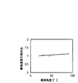
一方、図6は吸収液スラリ中の摩耗成分濃度が5%の場合における摩耗速度の衝突角度依存性を示したものである。使用した装置や測定条件などは図4の場合と同様である。
図中の横軸は吸収液スラリ流の衝突角度、縦軸は衝突角度45度における摩耗速度を1とした場合の相対摩耗速度を表している。なお、衝突角度45度を基準とした理由は、この角度が通常の噴射角度だからである。
On the other hand, FIG. 6 shows the collision angle dependence of the wear rate when the wear component concentration in the absorbent slurry is 5%. The used apparatus and measurement conditions are the same as in the case of FIG.
In the figure, the horizontal axis represents the collision angle of the absorbent slurry flow, and the vertical axis represents the relative wear rate when the wear rate is 1 at a collision angle of 45 degrees. The reason why the collision angle is 45 degrees is that this angle is a normal injection angle.
この図から明らかなように、吸収液スラリの衝突角度を低減させた場合でも、摩耗速度はほとんど変化せず、摩耗の抑制効果は限定的である。摩耗速度を抑制するには、吸収液スラリ流の吸収塔内壁への衝突速度を低下させることが効果的である。 As is clear from this figure, even when the collision angle of the absorbent slurry is reduced, the wear rate hardly changes and the wear suppression effect is limited. In order to suppress the wear speed, it is effective to reduce the collision speed of the absorbent slurry flow to the inner wall of the absorption tower.
しかし、吸収液スラリの噴霧条件は、吸収塔の大きさやスプレノズルの設置間隔等により最適になるように設定されていることから、変更することは容易ではない。
吸収液スラリは吸収塔内全体に噴霧されるが、殆どの吸収液は内壁に衝突せず、内壁に衝突する場合でも吸収液同士が衝突した後、間接的に衝突する場合が多い。また、一旦内壁に衝突してもそのまま流下するため、吸収液が直接衝突する内壁部分は限られる。しかし、噴霧吸収液が内壁に直接衝突する部分は特に摩耗が生じやすい。
However, it is not easy to change the spray condition of the absorbent slurry because it is set to be optimal depending on the size of the absorption tower, the installation interval of the spray nozzles, and the like.
Although the absorption liquid slurry is sprayed throughout the absorption tower, most of the absorption liquid does not collide with the inner wall, and even when it collides with the inner wall, the absorption liquid often collides indirectly after collision. Moreover, even if it collides once with the inner wall, it flows down as it is, so that the inner wall portion where the absorbing liquid directly collides is limited. However, the portion where the spray absorbing liquid directly collides with the inner wall is particularly susceptible to wear.
そこで、請求項1又は請求項4に記載の発明によれば、噴霧吸収液が吸収塔内壁に直接衝突しないように、その部分に液体を貯留した貯留部を設け、この液体に吸収液スラリを衝突させることによって、噴霧吸収液が間接的に内壁に衝突する。従って、各プラントにおける脱硫率等の運用条件などを変更することなく、噴霧吸収の内壁への衝突速度を低下させ、内壁の摩耗速度を減少させることが可能となる。 Therefore, according to the first or fourth aspect of the present invention, in order to prevent the spray absorption liquid from directly colliding with the inner wall of the absorption tower, a reservoir for storing the liquid is provided in that portion, and the absorption liquid slurry is added to the liquid. By causing the collision, the spray absorbing liquid indirectly collides with the inner wall. Therefore, it is possible to reduce the impact speed of spray absorption to the inner wall and reduce the wear speed of the inner wall without changing operating conditions such as the desulfurization rate in each plant.
特許文献2に記載の構成では、ガス抜け防止材や堰があるものの、これらは単に側壁を伝わって流下する吸収液スラリを集めて流す作用に留まる。堰などは噴霧吸収液が直接衝突する内壁部分に設置し、更に液を溜められるものでなければ内壁への吸収液スラリの衝突速度を低下させる作用は望めない。
In the configuration described in
液体としては、固体物が含まれることもある液状物でも良く、油や海水や工業用水なども含まれるが、これらの液体は生成する石膏を汚染するため、脱硫に用いる吸収液スラリを用いることが好ましい。吸収液スラリを用いることで、新たな動力を必要とせずに吸収塔内壁の摩耗を抑制することが可能である。 The liquid may be a liquid that may contain a solid material, including oil, seawater, industrial water, etc., but these liquids contaminate the gypsum produced, so use an absorbent slurry used for desulfurization. Is preferred. By using the absorbent slurry, it is possible to suppress the wear of the inner wall of the absorption tower without requiring new power.
また、吸収塔内に同一水平面上に並列配置された吸収液配管に設けられた複数のスプレノズルの中では、各吸収液配管の両端部に設置されるスプレノズルが他のスプレノズルに比べて吸収塔内壁に近接するため、内壁への衝突速度が大きく、吸収塔内壁の摩耗は、これら内壁に近接するスプレノズルからの噴霧液による影響が大きいと言える。 Also, among the plurality of spray nozzles provided in the absorption liquid pipes arranged in parallel on the same horizontal plane in the absorption tower, the spray nozzles installed at both ends of each absorption liquid pipe are the inner walls of the absorption tower as compared with other spray nozzles Therefore, it can be said that the wear speed of the inner wall of the absorption tower is greatly influenced by the spray liquid from the spray nozzle adjacent to the inner wall.
従って、請求項2又は請求項5に記載の発明によれば、請求項1又は請求項4に記載の発明の作用に加えて、各吸収液配管の両端部に設置されるスプレノズルからの噴霧吸収液が直接衝突する部分に貯留部を設けることで、効果的に吸収塔内壁の摩耗を防止できる。
Therefore, according to the invention of
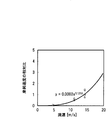
図7には、摩耗成分濃度が5%の場合における摩耗速度の吸収液スラリ流速依存性を示す。図中の横軸は吸収液スラリの材料への衝突速度(衝突流速)、縦軸は衝突速度15m/sを基準とした場合の摩耗速度の相対比である。使用した装置や測定条件などは図4の場合と同様である。なお、衝突速度=噴射速度とした。 FIG. 7 shows the absorption liquid slurry flow rate dependence of the wear rate when the wear component concentration is 5%. In the figure, the horizontal axis represents the collision speed (impact velocity) of the absorbent slurry with the material, and the vertical axis represents the relative ratio of the wear speed when the collision speed is 15 m / s. The used apparatus and measurement conditions are the same as in the case of FIG. The collision speed was set to the injection speed.
この結果より、摩耗速度は衝突速度の約3乗に比例しており、衝突速度の低減が摩耗抑制に有効であることが分かる。すなわち、吸収液スラリが衝突する内壁部分に、液体を溜めた貯留部を設けることで、噴霧された吸収液スラリは直接内壁には衝突せず、まず貯留部内の液体に衝突することで、速度が低下する。従って、摩耗速度は大幅に低減される。また、衝突速度が5m/s以下であれば摩耗量は実質的に無視できる値まで減少する。 From this result, it is understood that the wear speed is proportional to the third power of the collision speed, and that the reduction of the collision speed is effective in suppressing wear. In other words, by providing a storage part that stores liquid on the inner wall part where the absorbing liquid slurry collides, the sprayed absorbing liquid slurry does not directly collide with the inner wall, but first, it collides with the liquid in the storing part. Decreases. Thus, the wear rate is greatly reduced. Further, if the collision speed is 5 m / s or less, the amount of wear decreases to a value that can be substantially ignored.
一般に、吸収液スラリ流によるステンレス鋼の摩耗の発生には、臨界流速があることが知られており、下記の式(5)で表すことができる。
W=k(Vsinθ−A)×(Vcosθ−BVsinθ) (5)
ここで、W:損傷量(摩耗量に同じ)(mg/Kg)、V:粒子(摩耗成分粒子)の衝突速度(m/s)、θ:衝突角度(degree)、k:定数、A:垂直(材料面に対して垂直、図13のPの向き)方向に摩耗成分粒子が侵入するために必要な垂直速度の閾値、Bsinθ:水平方向(材料面に対して平行、図13のQの向き)に材料を押しのける(変形を与える)ために必要な水平速度の閾値である。
In general, it is known that there is a critical flow velocity in the occurrence of wear of stainless steel due to the absorbent slurry flow, and it can be expressed by the following equation (5).
W = k (Vsin θ−A) × (V cos θ−BV sin θ) (5)
Here, W: damage amount (same as wear amount) (mg / Kg), V: collision velocity (m / s) of particles (wear component particles), θ: collision angle (degree), k: constant, A: Threshold of vertical velocity required for the wear component particles to enter in the vertical direction (perpendicular to the material surface, direction P in FIG. 13), Bsin θ: horizontal direction (parallel to the material surface, Q in FIG. 13) This is the threshold of the horizontal velocity required to push the material in (direction).
図7の結果から、摩耗成分を5%含有する条件における閾値は流速5m/s前後であることが分かる。貯留部の液量が少なく、貯留高さ(液面高さ)が低いと、吸収液スラリ流の衝突速度を緩和する効果が減少してしまうが、閾値であるこの衝突速度以下まで衝突速度を減少させることが可能な高さに貯留することで摩耗速度の抑制が可能である。 From the results of FIG. 7, it can be seen that the threshold value under the condition of containing 5% of wear components is around 5 m / s. If the amount of liquid in the reservoir is small and the reservoir height (liquid level height) is low, the effect of reducing the collision speed of the absorbed liquid slurry flow will decrease, but the collision speed will be reduced below this threshold collision speed. By storing at a height that can be reduced, the wear rate can be suppressed.
液面高さと吸収液の衝突速度との関係は、以下のように求めることができる。まず、図8に示す装置を用いて、液面高さと摩耗速度との関係を求めた。スラリタンク31内にテストピース29を沈め、吸収液スラリの液面高さH(液面とテストピース29の衝突部位35間の距離)を変えてノズル25の先端部が液面に一致するようにノズル25を図示しない支持部材で支持しながら吸収液スラリを噴射した。図8(a)には正面断面図を図8(b)には側面断面図を示している。液面高さHはテストピース29の位置を変えることで変更した。測定条件は、図4の場合と同様に、吸収液スラリの温度は常温、試験時間は24時間(6時間×4日)、噴射速度を15m/s、噴射角度を45°とし、摩耗速度を24時間試験後の摩耗深さから算出した。摩耗深さは、表面粗さ計により測定した。図9に結果を示す。
The relationship between the liquid level height and the collision speed of the absorbing liquid can be obtained as follows. First, using the apparatus shown in FIG. 8, the relationship between the liquid level and the wear rate was determined. The
従って、この関係と図7のグラフから貯留高さと吸収液の衝突速度との関係を算出することで、衝突速度5m/s以下を達成する貯留高さを求めることができる。
なお、吸収塔内壁の壁面材料や吸収液スラリ中の摩耗成分濃度は、使用環境や運用条件によっても異なる。液体の貯留高さが高いと衝突の緩和作用が大きくなることから吸収液の衝突速度が低くなるため、貯留高さを、所定の摩耗速度(ほぼゼロに限らず、許容範囲で足りる)を満たす衝突速度となる高さ以上にすれば良い。
Accordingly, by calculating the relationship between the storage height and the collision speed of the absorbing liquid from this relationship and the graph of FIG. 7, the storage height that achieves a collision speed of 5 m / s or less can be obtained.
The wall material of the inner wall of the absorption tower and the wear component concentration in the absorbent slurry vary depending on the use environment and operating conditions. If the liquid storage height is high, the collision mitigating action increases, and the collision speed of the absorbing liquid decreases. Therefore, the storage height satisfies the predetermined wear speed (not limited to almost zero, but within an allowable range). What is necessary is just to make it the height which becomes a collision speed or more.
従って、請求項3又は請求項6に記載の発明によれば、請求項1又は請求項4、請求項2又は請求項5に記載の発明の作用に加えて、貯留部に、所定の摩耗速度を満たす衝突速度となる貯留高さ以上に液体を貯留することで、優れた摩耗抑制効果が発揮される。
Therefore, according to the invention described in
なお、円筒形の脱硫塔では、部位により内壁に近接するスプレノズルの内壁までの距離が異なるが、その最大距離に応じて貯留部の構造を変更する(例えば、内壁からの突出長さを変える)ことで、対応が可能である。 In the cylindrical desulfurization tower, the distance to the inner wall of the spray nozzle that is close to the inner wall differs depending on the site, but the structure of the reservoir is changed according to the maximum distance (for example, the protruding length from the inner wall is changed). This is possible.
本発明によれば、石灰石−石膏法排煙脱硫装置において、激しい摩耗損傷が懸念される、石灰石の純度が低い低品位石灰石を用いた場合でも、吸収塔内壁の壁面材料を変更することなく、高い耐摩耗性を付与することが可能である。また、吸収塔内壁の年間の摩耗速度を減少させることができるため、ライニング施工時に想定される短期間での補修メンテナンスが不要となる。 According to the present invention, in the limestone-gypsum flue gas desulfurization apparatus, there is a concern about severe wear damage, even when using low-grade limestone with low limestone purity, without changing the wall surface material of the absorption tower inner wall, High wear resistance can be imparted. In addition, since the annual wear rate of the inner wall of the absorption tower can be reduced, repair maintenance in a short period assumed at the time of lining construction becomes unnecessary.
すなわち、請求項1又は請求項4に記載の発明によれば、噴霧吸収液が直接内壁には衝突せず、貯留部内の液体に当たってから衝突することで内壁への衝突速度が低下するため、内壁の摩耗速度を減少させることができる。
That is, according to the invention described in
請求項2又は請求項5に記載の発明によれば、請求項1又は請求項4に記載の発明の作用に加えて、吸収塔内壁に近接するスプレノズルからの噴霧液の衝突速度が低下するため、効果的に吸収塔内壁の摩耗を防止できる。
According to the invention described in
また、請求項3又は請求項6に記載の発明によれば、請求項1又は請求項4、請求項2又は請求項5に記載の発明の効果に加えて、液体の貯留高さを、所定の摩耗速度を満たす衝突速度となる高さ以上にすることで、より吸収塔内壁の摩耗の抑制効果を向上させることができ、また摩耗速度が無視できる程度の衝突速度にすることもできる。
According to the invention described in
以下に、本発明の実施の形態を示す。 Embodiments of the present invention are shown below.
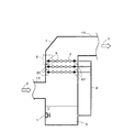
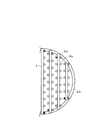
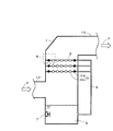
図1には、本発明の一実施例である排煙脱硫装置の吸収塔1の側面図を示す(内部も示している)。図2には、図1の吸収塔の吸収液配管2部分の平面図(一部)を示し、図3には、図1の内壁近傍のスプレ部5の拡大図を示す。
In FIG. 1, the side view of the
火力発電所や工場等に設置されるボイラ等の燃焼装置から排出される硫黄酸化物を含む排ガスは、図示していない脱硫ファンにより入口ダクト12から矢印X方向(ほぼ水平方向)に流れて吸収塔1に導入された後、上昇し、出口ダクト13から矢印Y方向に排出される。この間、石灰石又は石灰を含むスラリなどの吸収剤を含んだ吸収液が吸収液配管2を通じ、吸収塔1内に一定間隔で設置されているスプレノズル3から噴霧され、排ガスとの気液接触により、前記(1)〜(4)で示す脱硫反応が生じる。
Exhaust gas containing sulfur oxides discharged from a combustion apparatus such as a boiler installed in a thermal power plant or factory flows through the
スプレノズル3から微細な液滴として噴霧される吸収剤の液滴と排ガスとを接触させることで、排ガス中のばいじんやHCl、HF等の酸性ガスと共に、排ガス中のSOxはスプレノズル3の吸収液滴表面で化学的に吸収、除去される。
By bringing the absorbent droplet sprayed as fine droplets from the
SOxを吸収した吸収液は、一旦吸収塔1の底部の循環タンク6に溜まり、酸化用撹拌機7によって撹拌されながら、図示しない空気供給管から供給される空気中の酸素により酸化され、石膏を生成する。ボイラ等からの排ガスに含まれるSOx量に応じて、図示しない吸収剤スラリ(主に石灰石スラリ)供給ラインから吸収剤が供給される。炭酸カルシウム及び石膏が共存する循環タンク6にあるスラリ状の吸収液の一部は、図示しない吸収液循環ポンプにより昇圧され、吸収液循環配管8を経由して、吸収塔1内の上部の吸収液配管2に供給され、一部は図示しない吸収液抜き出し管より図示しない廃液処理・石膏回収系へと送られる。
The absorbing solution that has absorbed SOx once accumulates in the
このように、吸収液スラリは吸収塔1内全体に噴霧されるが、殆どの吸収液は内壁に衝突せず、内壁に衝突する場合でも吸収液同士が衝突した後、間接的に衝突する場合が多い。また、一旦内壁に衝突してもそのまま流下するため、吸収液スラリが直接衝突する内壁部分は限られ、特に塔中心から外側にある、内壁に近接するスプレノズル3からの噴霧吸収液が内壁に直接衝突しやすい。
Thus, although absorption liquid slurry is sprayed in the
図2に示す例では、複数の吸収液配管2が吸収塔1内に同一水平面上に並列配置されており(図示例では平行である)、各吸収液配管2の両端部に設けられたスプレノズル(色の付いたスプレノズル)3aが他のスプレノズル3bに比べて内壁に近接しているため、これらのスプレノズル3aからの噴霧液は、他のスプレノズル3bからの噴霧液に比べて内壁への衝突速度が非常に大きいと言える。
In the example shown in FIG. 2, a plurality of absorbent
そこで、本実施例では、スプレノズル3aからの吸収液スラリが衝突する内壁部分に、吸収液スラリを溜めた樋(貯留部)20を設け、樋20内の吸収液スラリにスプレノズル3から噴霧される吸収液スラリを当てることによって内壁への衝突速度を低下させ、内壁の摩耗速度を減少させている。なお、本実施例では、分かりやすいように各吸収液配管2の両端部に設けられたスプレノズル3aを吸収塔1の内壁に近接するノズルとしているが、各吸収液配管2の両端部のスプレノズル3aに限らず、それ以外のスプレノズル3bであっても、内壁に近くて内壁部分への衝突速度が、基準とする衝突速度(摩耗が実質的に無視できる程度の速度であり、例えば、摩耗成分濃度が5%の場合は5m/s)以上となるスプレノズル3a(又は3b)を対象とすると良い。
Therefore, in this embodiment, a soot (reservoir) 20 storing the absorbent slurry is provided on the inner wall portion where the absorbent slurry from the spray nozzle 3a collides, and sprayed from the
また、吸収液配管2は上下方向に複数段(図示例では3段)設置されているため、各段に樋20を設置すると良い。なお、樋20の位置は、吸収液スラリの噴霧条件によっても違ってくるが、各プラントにおける運用条件はほぼ決まっているため、各プラントに合わせて特に摩耗が激しいと予測される位置に設置すると良い。
Moreover, since the
本実施例により、噴霧された吸収液スラリは直接内壁には衝突せず、まず樋20内の吸収液スラリに衝突することで、流速が低下する。その後、間接的に内壁に衝突するため、摩耗速度は大幅に低減される。例えば、樋20は断面L字型や断面コの字型(断面U字型でも良い)の部材から形成される。素材は、ポリプロピレン(PP)樹脂、炭化ケイ素(SiC)などで良い。
According to the present embodiment, the sprayed absorbent slurry does not directly collide with the inner wall, but first collides with the absorbent slurry in the
樋20内には液体を溜めれば良く、液体として固体物が含まれることもある液状物や油、海水、工業用水等も含まれるが、循環タンク6内に液体が流入する場合を考慮すると、生成する石膏を汚染するため、脱硫に用いる吸収液スラリを用いることが好ましい。この場合は、新たな動力を必要とせずに吸収塔内壁の摩耗を抑制することが可能である。
It is only necessary to store liquid in the
摩耗対策の対象とするスプレノズル3は、例えば吸収液スラリ中の摩耗成分(SiO2及びAl2O3)濃度が5%の場合(低品位石灰石を用いた場合に想定される濃度)には、吸収塔1の設計上の壁面への吸収液スラリの衝突速度(先の基準とする衝突速度)が5m/s以上のものとする。なお、この基準となる衝突速度は、各予想環境において実施する予備試験により決定される。すなわち、各プラントのスラリ中の摩耗成分濃度を用いた摩耗試験により、決定される。 For example, when the wear component (SiO 2 and Al 2 O 3 ) concentration in the absorbing liquid slurry is 5% (concentration assumed when low-grade limestone is used), The collision speed of the absorbing liquid slurry on the designed wall surface of the absorption tower 1 (the collision speed based on the previous reference) is 5 m / s or more. The reference collision speed is determined by a preliminary test performed in each predicted environment. That is, it is determined by the wear test using the wear component concentration in the slurry of each plant.
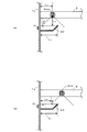
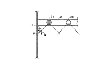
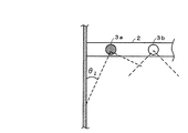
また、スプレノズル3と内壁との距離は、円筒形の吸収塔に設置される場合は部位により異なる。図3(a)には、各吸収液配管2の両端部のスプレノズル3aのうち、内壁に最も近接するスプレノズル3aaを示し、図3(b)には、各吸収液配管2の両端部のスプレノズル3aのうち、内壁に最も遠いスプレノズル3abを示しており、図3(a)、図3(b)共に衝突角度θが45°の場合を示している。
In addition, the distance between the
まず、樋20及び液面の高さ方向の位置は、最も近接するスプレノズル3aaを基準とする。スプレノズル3aaと液面間の距離L3が壁面1aとスプレノズル3aa間の距離L2よりも小さくなるようにする(L3<L2)。その理由は、衝突角度θが45°の場合はL3をL2よりも大きくすると、噴射されたスラリ吸収液が液面に到達せずに壁面1aに直接衝突してしまうからである。そして、樋20及び液面の水平方向の位置は、対象とするスプレノズル3a(この例では衝突速度が5m/s以上のもの)のうち、最も遠いスプレノズル3abを基準とする。樋20の上部の突出長さL1が、スプレノズル3abから噴射されたスラリ吸収液が液面に到達する位置と壁面1a間の距離L4よりも大きくなるようにする(L4<L1)。L4<L1とすることで、樋20内の液で噴射されたスラリ吸収液を受けることができる。
First, the position in the height direction of the
なお、円筒形の脱硫塔では、部位により内壁に近接するスプレノズル3の内壁までの距離が異なるため、その最大距離に応じて上記L1を変更すれば良い。
また、図7からも明らかなように、衝突速度が5m/s以下であれば摩耗量は実質的に無視できる値まで減少する。図10には、貯留部内の液面高さと吸収液スラリの衝突速度(衝突流速)との関係を示す。このグラフは、吸収塔1の内壁材料(SUS316L)表面の液面高さと摩耗速度の減少を実験的に評価した結果である。横軸は吸収液スラリの液面高さを示し、縦軸は各液面高さ条件における摩耗速度から衝突速度を算出したものである。各液面高さ条件における摩耗速度は、図9に示した通りである。図9には液面高さが17mm程度までしか示していないが、それ以降は予測値により求めることができる。
In the cylindrical desulfurization tower, since the distance to the inner wall of the
Further, as is apparent from FIG. 7, if the collision speed is 5 m / s or less, the amount of wear decreases to a value that can be substantially ignored. In FIG. 10, the relationship between the liquid level height in a storage part and the collision speed (collision flow velocity) of an absorption liquid slurry is shown. This graph is a result of experimentally evaluating the decrease in the liquid level and wear rate on the surface of the inner wall material (SUS316L) of the
なお、図3ではスプレノズル3aaと液面間の距離L3があり、実際はスプレノズル3aと液面との間に空間部を有するが、図8に示す装置ではノズル25の先端部が液面に一致する条件とした。その理由は、前記空間部があってもスプレノズル3aから噴霧される吸収液が受ける空気抵抗や排ガス流れや重力などによって減速又は増速される吸収液の速度に比べて、液に流入してから減速する速度変化の方が大きいため、前記空間部による吸収液の速度変化は無視できるという前提による。
In FIG. 3, there is a distance L 3 between the spray nozzle 3aa and the liquid level, and actually there is a space between the spray nozzle 3a and the liquid level, but in the apparatus shown in FIG. 8, the tip of the
また、噴射された吸収液スラリが液面で跳ね返ってから壁面1aに当たる場合は減速度合が大きいため、摩耗にはほとんど影響しないと思われる。従って、この条件では液中に進入した吸収液スラリがそのまま進んで壁面1aに衝突する場合を想定している。そして、衝突角度の条件を揃えるために図8のノズル25は拡散して噴射するノズルではなく、真下に噴射するノズルを用いた。ノズル25の先端とテストピース29との距離は十分短いため、図8におけるHは壁面1aに設ける液の厚み(壁面1aに対して垂直方向の高さ)にほぼ相当し、ここで、吸収液スラリの衝突角度は45°であることから、この厚みが液面高さH1になるという考え方である。なお、吸収液スラリの噴射角度を変えた場合は、図8に示す装置の条件もそれに合わせて変えれば、図9に示すデータが取れることは言うまでもない。
In addition, when the injected absorbent slurry bounces off the liquid surface and hits the wall surface 1a, it is considered that there is little influence on the wear because the degree of deceleration is large. Therefore, under this condition, it is assumed that the absorbing liquid slurry that has entered the liquid advances as it is and collides with the wall surface 1a. And in order to make the conditions of a collision angle uniform, the
そして、図10からも分かるように、樋20内に吸収液スラリを溜めた場合、摩耗抑制の閾値である流速5m/s以下まで衝突速度を低下させるためには、吸収液スラリの液面高さH1を22.5mm以上とすることが必要であるが、誤差等を考慮すると25mm以上確保すれば良い。従って、高さ(貯留高)が25mm以上の樋20を用いて、吸収液スラリを液面高さH1が25mm以上になるように溜めておくことで、摩耗速度の大幅な低減が可能である。スプレノズル3からは常時吸収液スラリが噴霧されているので、排煙脱硫装置の運転前に樋20内に吸収液スラリを貯留しておけば、その後補給する必要もない。
As can be seen from FIG. 10, in the case where the absorbent slurry is accumulated in the
以上説明したように、本実施例で示した吸収塔1の内壁構造は、複数のスプレノズル3の中で内壁に近接するスプレノズル3aからの吸収液スラリが直接衝突する部分に吸収液スラリを溜めた樋20を形成することで、吸収液スラリの衝突速度を低下させ、摩耗を抑制するものである。本実施例により、内壁の摩耗による損傷は大幅に低減される。
As described above, the inner wall structure of the
なお、本実施例は、摩耗成分であるSiO2、Al2O3を1%以上含有する低品位石灰石を吸収液に用いた場合のみならず、高品位石灰石を吸収液に用いた場合の排煙脱硫装置や除塵塔にも適用可能である。 In this example, not only the use of low-grade limestone containing 1% or more of wear components SiO 2 and Al 2 O 3 in the absorption liquid but also the discharge when high-grade limestone is used in the absorption liquid. It can also be applied to smoke desulfurization equipment and dust removal towers.
排煙脱硫装置に限らず、その他の排煙装置にも利用可能性がある。 The present invention is not limited to flue gas desulfurization devices but may be used for other flue gas exhaust devices.
1 吸収塔 2 吸収液配管
3 スプレノズル 4,5 内壁近傍のスプレ部
6 循環タンク 7 攪拌機
8 吸収液循環配管 12 入口ダクト
13 出口ダクト 20 樋
21 スラリタンク 23 ポンプ
25 スプレノズル 27 スラリライン
29 テストピース 31 スラリタンク
35 衝突部位
DESCRIPTION OF
Claims (6)
吸収塔内壁の噴霧吸収液が直接衝突する部分に、噴霧吸収液を受けて吸収液の吸収塔内壁への衝突速度を緩和する液体を貯留した貯留部を設けたことを特徴とする排煙脱硫装置。 Smoke with an absorption tower that introduces exhaust gas discharged from a combustion device including a boiler, sprays an absorption liquid containing slurry containing limestone or lime, and absorbs and removes sulfur oxides contained in the exhaust gas In desulfurization equipment,
A flue gas desulfurization characterized in that a storage part for storing a liquid that reduces the collision speed of the absorbing liquid to the absorption tower inner wall by receiving the spray absorbing liquid is provided in a part where the spray absorbing liquid directly collides with the absorption tower inner wall apparatus.
前記貯留部は、各吸収液配管の両端部に設置されるスプレノズルからの噴霧吸収液が直接衝突する部分に設けられていることを特徴とする請求項1記載の排煙脱硫装置。 The absorption tower includes a plurality of spray nozzles for spraying an absorption liquid, and a plurality of absorption liquid pipes arranged in parallel on the same horizontal plane and having the plurality of spray nozzles,
2. The flue gas desulfurization apparatus according to claim 1, wherein the storage portion is provided in a portion where spray absorption liquid from spray nozzles installed at both ends of each absorption liquid pipe directly collides.
吸収塔内壁の噴霧吸収液が直接衝突する部分に、液体を貯留し、噴霧吸収液を前記液体で受けることで吸収塔内壁への衝突速度を緩和させることを特徴とする排煙脱硫方法。 The exhaust gas discharged from the combustion apparatus including the boiler is introduced into an absorption tower having a configuration in which an absorption liquid containing a slurry containing limestone or lime is sprayed to absorb and remove sulfur oxides contained in the exhaust gas. In the flue gas desulfurization method,
A flue gas desulfurization method characterized in that a liquid is stored in a portion of the inner wall of the absorption tower where the spray absorption liquid directly collides, and the collision absorption rate on the inner wall of the absorption tower is reduced by receiving the spray absorption liquid with the liquid.
各吸収液配管の両端部に設置されるスプレノズルからの噴霧吸収液が直接衝突する部分に液体を貯留することを特徴とする請求項4記載の排煙脱硫方法。 The absorption tower includes a plurality of spray nozzles for spraying an absorption liquid, and a plurality of absorption liquid pipes arranged in parallel on the same horizontal plane and having the plurality of spray nozzles,
5. The method of desulfurizing flue gas according to claim 4, wherein the liquid is stored in a portion where the spray absorbing liquid from the spray nozzles installed at both ends of each absorbing liquid pipe directly collides.
Priority Applications (1)
| Application Number | Priority Date | Filing Date | Title |
|---|---|---|---|
| JP2013264321A JP2015120102A (en) | 2013-12-20 | 2013-12-20 | Flue gas desulfurizer and flue gas desulfurization method |
Applications Claiming Priority (1)
| Application Number | Priority Date | Filing Date | Title |
|---|---|---|---|
| JP2013264321A JP2015120102A (en) | 2013-12-20 | 2013-12-20 | Flue gas desulfurizer and flue gas desulfurization method |
Publications (1)
| Publication Number | Publication Date |
|---|---|
| JP2015120102A true JP2015120102A (en) | 2015-07-02 |
Family
ID=53532291
Family Applications (1)
| Application Number | Title | Priority Date | Filing Date |
|---|---|---|---|
| JP2013264321A Pending JP2015120102A (en) | 2013-12-20 | 2013-12-20 | Flue gas desulfurizer and flue gas desulfurization method |
Country Status (1)
| Country | Link |
|---|---|
| JP (1) | JP2015120102A (en) |
Cited By (4)
| Publication number | Priority date | Publication date | Assignee | Title |
|---|---|---|---|---|
| JP2017136570A (en) * | 2016-02-05 | 2017-08-10 | 旭化成株式会社 | Water treatment method and water treatment system |
| CN107754602A (en) * | 2017-11-21 | 2018-03-06 | 湖南内特环保科技有限公司 | Containing ammonia and ammonium sulfide waste gas processing method and system |
| KR101920338B1 (en) | 2016-12-20 | 2018-11-20 | 디에스티주식회사 | Method for Adjusting Particle Size of Alkaline Wet Flue Gas Desulfurizing Agent and Method for Wet Flue Gas Desulfurization Using the Same |
| WO2019123925A1 (en) * | 2017-12-20 | 2019-06-27 | 三菱日立パワーシステムズ株式会社 | Spray pipe, desulfurization device equipped with same, and method of inspecting same |
-
2013
- 2013-12-20 JP JP2013264321A patent/JP2015120102A/en active Pending
Cited By (6)
| Publication number | Priority date | Publication date | Assignee | Title |
|---|---|---|---|---|
| JP2017136570A (en) * | 2016-02-05 | 2017-08-10 | 旭化成株式会社 | Water treatment method and water treatment system |
| KR101920338B1 (en) | 2016-12-20 | 2018-11-20 | 디에스티주식회사 | Method for Adjusting Particle Size of Alkaline Wet Flue Gas Desulfurizing Agent and Method for Wet Flue Gas Desulfurization Using the Same |
| CN107754602A (en) * | 2017-11-21 | 2018-03-06 | 湖南内特环保科技有限公司 | Containing ammonia and ammonium sulfide waste gas processing method and system |
| WO2019123925A1 (en) * | 2017-12-20 | 2019-06-27 | 三菱日立パワーシステムズ株式会社 | Spray pipe, desulfurization device equipped with same, and method of inspecting same |
| JP2019108962A (en) * | 2017-12-20 | 2019-07-04 | 三菱日立パワーシステムズ株式会社 | Spray pipe, desulfurization device equipped with the same, and method of inspecting the same |
| JP7009200B2 (en) | 2017-12-20 | 2022-01-25 | 三菱パワー株式会社 | Spray pipe, desulfurization device equipped with it and its inspection method |
Similar Documents
| Publication | Publication Date | Title |
|---|---|---|
| CN103338841B (en) | Wet scrubber and method for cleaning process gas | |
| US9550145B2 (en) | Exhaust gas treatment apparatus, ship, and exhaust gas treatment method | |
| JP5234783B2 (en) | Wet flue gas desulfurization equipment | |
| JP4845568B2 (en) | Wet flue gas desulfurization equipment | |
| US8968691B2 (en) | Treatment method and treatment facilities of exhaust gas | |
| JP5479741B2 (en) | Wet flue gas desulfurization equipment | |
| JP6230818B2 (en) | Exhaust gas treatment apparatus and exhaust gas treatment method | |
| US20150139881A1 (en) | Wet type flue-gas desulfuization apparatus and method for adjusting oxidation reduction potential of absorbent therefor | |
| CN202010513U (en) | Downstream jet bubbling wet-method desulfurizing device | |
| KR20110020194A (en) | Flue gas cleaning system and method | |
| JP5967306B2 (en) | Desulfurization equipment | |
| JP2013006125A (en) | Wet flue gas desulfurization apparatus, and wet flue gas desulfurization method | |
| KR101473285B1 (en) | Wet flue gas desulfurization device | |
| JP2015120102A (en) | Flue gas desulfurizer and flue gas desulfurization method | |
| CN105056746A (en) | Method for realizing boiler flue gas integrated distributed desulfurization and denitrification process | |
| CN105032145A (en) | Boiler flue gas integration distributing type SOx/NOx control device | |
| JP2016120438A (en) | Wet-type desulfurization apparatus and wet-type desulfurization method | |
| JP4905926B2 (en) | Two-chamber wet flue gas desulfurization system | |
| JP3831136B2 (en) | Method and apparatus for controlling bubble content in liquid | |
| JP2016087539A (en) | Method for exhaust gas desulfurization and removing soot and dust | |
| JP5289668B2 (en) | Wet flue gas desulfurization equipment | |
| JP5019361B2 (en) | How to cope with increase of absorbent slurry concentration in flue gas desulfurization equipment | |
| JPH11347352A (en) | Wet exhaust desulfurizing method and apparatus | |
| KR200309272Y1 (en) | Apparatus for Cleaning Duct Pipe in Desulfurization Equipments | |
| JPH05285339A (en) | Wet desulfurizer for flue gas |