JP2015138363A - Handling device - Google Patents
Handling device Download PDFInfo
- Publication number
- JP2015138363A JP2015138363A JP2014009127A JP2014009127A JP2015138363A JP 2015138363 A JP2015138363 A JP 2015138363A JP 2014009127 A JP2014009127 A JP 2014009127A JP 2014009127 A JP2014009127 A JP 2014009127A JP 2015138363 A JP2015138363 A JP 2015138363A
- Authority
- JP
- Japan
- Prior art keywords
- gear shaft
- shaft
- gear
- operating device
- groove
- Prior art date
- Legal status (The legal status is an assumption and is not a legal conclusion. Google has not performed a legal analysis and makes no representation as to the accuracy of the status listed.)
- Granted
Links
- 238000003780 insertion Methods 0.000 claims abstract description 27
- 230000037431 insertion Effects 0.000 claims abstract description 27
- 230000002093 peripheral effect Effects 0.000 claims description 15
- 210000000078 claw Anatomy 0.000 claims description 13
- 230000035807 sensation Effects 0.000 claims description 9
- 230000009191 jumping Effects 0.000 abstract description 4
- 230000006870 function Effects 0.000 description 3
- 230000000694 effects Effects 0.000 description 2
- 238000004378 air conditioning Methods 0.000 description 1
- 238000005452 bending Methods 0.000 description 1
- 239000012141 concentrate Substances 0.000 description 1
- 230000001143 conditioned effect Effects 0.000 description 1
- 239000000463 material Substances 0.000 description 1
- 238000012986 modification Methods 0.000 description 1
- 230000004048 modification Effects 0.000 description 1
Images


Landscapes
- Mechanical Control Devices (AREA)
- Air-Conditioning For Vehicles (AREA)
Abstract
Description
本発明は、ベース部材にギアシャフトを回転可能に組み付けたダイヤル式の操作装置に関する。 The present invention relates to a dial type operation device in which a gear shaft is rotatably assembled to a base member.
装置正面側にダイヤル式で回転式の操作ノブ(回転摘み)が配置された操作装置が多用されている。このような操作装置では、ギアシャフトが挿入されてアーム等の連動部材のギアに噛み合い、更に、操作ノブがギアシャフトに装置正面側から差し込まれて連結されている。 An operation device in which a dial-type rotary operation knob (rotary knob) is arranged on the front side of the device is often used. In such an operation device, a gear shaft is inserted and meshed with a gear of an interlocking member such as an arm, and an operation knob is inserted and connected to the gear shaft from the front side of the device.
このような操作装置では、操作装置を構成するベース部材の周壁に溝を配列し、ギアシャフトに取り付けられるスプリングおよびボールと上記溝とによって、操作ノブを操作した際のクリック感(節度感)を発生させるダイヤル式操作装置が提案されている(例えば特許文献1参照)。 In such an operating device, grooves are arranged on the peripheral wall of the base member constituting the operating device, and a click feeling (moderation feeling) when operating the operating knob is achieved by a spring and a ball attached to the gear shaft and the groove. A dial type operating device has been proposed (see, for example, Patent Document 1).
ところで、このような従来の操作装置では、ギアシャフトをベース部材に取り付ける際に、ギアシャフトとベース部材との間にスプリングとボールとを組み込む必要がある。このため、作業者は、スプリングとボールとの組み込みに集中しており、ギアシャフトのギア(駆動ギア)とアームのギア(従動ギア)とが正しい相互位置となるように組み込むことに充分な注意を払うことが難しい。この結果、ギアシャフトのギアと連動部材のギアとが正しい位置に噛み合わずにいわゆるギア飛び状態で噛み合ってしまうことがあった。 By the way, in such a conventional operating device, when the gear shaft is attached to the base member, it is necessary to incorporate a spring and a ball between the gear shaft and the base member. For this reason, the operator concentrates on the assembly of the spring and the ball, and is careful enough to incorporate the gear shaft gear (drive gear) and the arm gear (driven gear) so that they are in the correct mutual position. Difficult to pay. As a result, the gear of the gear shaft and the gear of the interlocking member may be engaged with each other in a so-called gear jump state without being engaged at the correct position.
そこで、本発明は、組み立て中にいわゆるギア飛びで噛み合うことを防止した操作装置を提供することを課題とする。 Then, this invention makes it a subject to provide the operating device which prevented meshing | engagement by what is called a gear jump during an assembly.
上記目的を達成するため本発明は、ベース部材に設けられたシャフト取付用筒部の内部に挿入配置され、シャフト取付用筒部に対してシャフト軸支部によって回転可能で且つ軸線方向へ移動不能に係止保持されるギアシャフトと、ギアシャフトの回転に伴いギアシャフトに節度感を発生させる節度感発生部とを備える。ギアシャフトには駆動ギアが設けられ、ベース部材に取り付けられるアーム部材に設けられた従動ギアと駆動ギアとが嵌合駆動する構成にされている。また、節度感発生部が、シャフト取付用筒部の内周面に対し、周方向に沿って複数設けられた軸線方向へ延びる節度感発生用溝部と、ギアシャフトから半径方向へ突設された筒状保持部材と、該筒状保持部材の内部に弾性体を介して出入自在に収容保持されることにより、シャフト取付用筒部の内周面の節度感発生用溝部が設けられた部分に弾性体の弾性力によって弾接可能な弾接部材と、を有する。そして、ギアシャフトをベース部材へ挿入する途中でギアシャフトを仮保持可能な一時停止構造を操作装置が有し、ギアシャフトの一時停止時には、駆動ギアと従動ギアとが少なくとも一部嵌合状態となる。 In order to achieve the above object, the present invention is inserted and arranged inside a shaft mounting cylinder provided in a base member, and is rotatable with respect to the shaft mounting cylinder by a shaft shaft support and cannot move in the axial direction. A gear shaft that is locked and held, and a moderation feeling generating unit that generates a moderation feeling in the gear shaft as the gear shaft rotates. A drive gear is provided on the gear shaft, and a driven gear and a drive gear provided on an arm member attached to the base member are configured to be fitted and driven. Further, a moderation sensation generating portion is provided in a radial direction from the gear shaft and a moderation sensation generating groove portion extending in the axial direction along the circumferential direction with respect to the inner peripheral surface of the shaft mounting cylinder portion. A cylindrical holding member and a portion for providing a moderation sensation generating groove on the inner peripheral surface of the cylindrical portion for shaft mounting by being accommodated and held inside the cylindrical holding member so as to be freely inserted and removed through an elastic body. And an elastic contact member that can be elastically contacted by the elastic force of the elastic body. The operating device has a temporary stop structure capable of temporarily holding the gear shaft in the middle of inserting the gear shaft into the base member, and when the gear shaft is temporarily stopped, the drive gear and the driven gear are at least partially engaged. Become.
本発明によれば、組み立て中にいわゆるギア飛びで噛み合うことを防止した操作装置とすることができる。 According to the present invention, it is possible to provide an operating device that prevents so-called gear jumping and meshing during assembly.
以下、添付図面を参照して、本発明の実施の形態について説明する。なお、以下の説明では、すでに説明したものと同一または類似の構成要素には同一または類似の符号を付し、その詳細な説明を適宜省略する。 Embodiments of the present invention will be described below with reference to the accompanying drawings. In the following description, the same or similar components as those already described are denoted by the same or similar reference numerals, and detailed description thereof will be omitted as appropriate.
また、図面は模式的なものであり、寸法比などは現実のものとは異なることに留意すべきである。従って、具体的な寸法比などは以下の説明を参酌して判断すべきものである。図面相互間においても互いの寸法の関係や比率が異なる部分が含まれていることはもちろんである。 In addition, it should be noted that the drawings are schematic and the dimensional ratios and the like are different from actual ones. Therefore, specific dimensional ratios and the like should be determined in consideration of the following description. Of course, the drawings include portions having different dimensional relationships and ratios.
また、以下に示す実施の形態は、この発明の技術的思想を具体化するための例示であって、この発明の実施の形態は、構成部品の材質、形状、構造、配置等を下記のものに特定するものではない。この発明の実施の形態は、要旨を逸脱しない範囲内で種々変更して実施できる。 The following embodiments are exemplifications for embodying the technical idea of the present invention, and the embodiments of the present invention are described below in terms of the material, shape, structure, arrangement, etc. of the components. It is not something specific. The embodiments of the present invention can be implemented with various modifications without departing from the scope of the invention.
また、以下に示す実施の形態では、図面では歯車として傘歯車しか描いていないが、平歯車などの他の種類の歯車を用いてもよい。 In the embodiment shown below, only a bevel gear is depicted as a gear in the drawings, but other types of gears such as a spur gear may be used.
また、以下に示す実施の形態では、特に自動車に搭載されて車内に空調風を供給する空調ユニットに組み込まれるのに最適な操作装置を説明するが、自動車以外の操作装置に適用することはもちろん可能である。 Further, in the embodiment described below, an operation device that is particularly suitable for being incorporated in an air conditioning unit that is mounted in a vehicle and supplies conditioned air to the inside of the vehicle will be described, but of course, it can be applied to an operation device other than a vehicle. Is possible.
[第1実施形態]
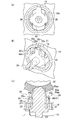
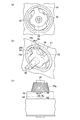
まず、第1実施形態について説明する。図1は、本実施形態(以下、本実施形態という)の操作装置の正面斜視図である。図2は、本実施形態の操作装置を構成するベース部材の正面斜視図である。図3(a)〜(c)は、それぞれ、本実施形態の操作装置の組み立て途中におけるベース部材とギアシャフトとの相対位置を示す正面図、正面斜視図、および、平面断面図である。図4(a)〜(c)は、それぞれ、本実施形態の操作装置の組み立て後におけるベース部材とギアシャフトとの相対位置を示す正面図、正面斜視図、および、平面断面図である。
[First Embodiment]
First, the first embodiment will be described. FIG. 1 is a front perspective view of an operating device of the present embodiment (hereinafter referred to as the present embodiment). FIG. 2 is a front perspective view of the base member constituting the operating device of the present embodiment. 3A to 3C are respectively a front view, a front perspective view, and a plan sectional view showing the relative positions of the base member and the gear shaft during the assembly of the operating device of the present embodiment. 4A to 4C are respectively a front view, a front perspective view, and a plan sectional view showing the relative positions of the base member and the gear shaft after assembly of the operating device of the present embodiment.
本実施形態の操作装置10は、自動車の室内などに配置されているものであり、ベース部材12と、ベース部材12の手前側(操作側)に組み付けられた表示パネル14とを備えている。表示パネル14には、ダイヤル式の操作用のノブ16が取り付けられている。
The
この操作装置10は、ベース部材12に設けられたシャフト取付用筒部18と、シャフト取付用筒部18の内部に挿入配置されたギアシャフト20と、ギアシャフト20の回転に伴いギアシャフト20に節度感を発生させる節度感発生部21と、を備えている。ギアシャフト20は、シャフト取付用筒部18に対してシャフト軸支部18s(後述の図5、図6参照)によって回転可能で且つ軸線方向へ移動不能に係止保持されている。なお、図2で節度感発生部21a、21bを示しているが、両者は節度感(クリック感)を発生させるギアシャフト回転角度が異なることだけで作用は同等なので、以下の説明では節度感発生部21aを節度感発生部21として説明し、節度感発生部21bの説明を省略する。
The
ギアシャフト20には駆動ギア20gが設けられ、ベース部材12に取り付けられるアーム部材22(図3(c)、図4(c)参照)に設けられた従動ギア22gと駆動ギア20gとが嵌合駆動する構成にされている。
The
そして、節度感発生部21は、シャフト取付用筒部18の内周面に対し、周方向に沿って複数設けられた軸線方向へ延びる節度感発生用溝部18dと、ギアシャフト20から半径方向へ突設された筒状保持部材20hと、筒状保持部材20hの内部に弾性体24(例えばコイルバネ)を介して出入自在に収容保持されることにより、シャフト取付用筒部18の内周面の節度感発生用溝部18dが設けられた部分に弾性体24の弾性力によって弾接可能な弾接部材26(例えば球状部材)と、を有する。節度感発生用溝部18dは、何れもシャフト取付用筒部18の中心軸に沿って形成されており、ノブ16の回転に伴って、すなわちギアシャフト20の回転に伴って、弾接部材26が各溝部に当接する際にノブ16に節度感(クリック感)が伝わるようになっている。
The moderation
そして、ギアシャフト20をベース部材12へ挿入する途中でギアシャフト20を仮保持可能な一時停止構造28を操作装置10が有しており、一時停止構造28によるギアシャフト20の一時停止時には、ギアシャフト20に設けられた駆動ギア20gとアーム部材22に設けられた従動ギア22gとが少なくとも一部嵌合状態となっている(例えば、図3(c)に示すように、駆動ギア部分20gpと従動ギア部分22gpとが嵌合状態(噛み合っている状態)になっている)。
The operating
本実施形態では、一時停止構造28は、シャフト取付用筒部18の内周面に設けられている。そして、一時停止構造28は、ギアシャフト20に設けられた嵌合爪30(図3(c)、図4(c)参照)が、シャフト取付用筒部18へ挿入中に挿入抵抗となる抵抗部31となっている。
In the present embodiment, the
本実施形態では、ギアシャフト20には、ギアシャフト基端側の外周部からギアシャフト先端側に向けて棒状に延び出してギアシャフト径方向に弾性変形可能な少なくとも2本の延出し部32が形成されており、嵌合爪30は各延出し部32の先端側に設けられていて、ギアシャフト外周側へ張出している。嵌合爪30は、ギアシャフト先端側からギアシャフト基端側にかけてギアシャフト径方向外側に徐々に広がる斜面30sを有する。
In the present embodiment, the
そして、シャフト取付用筒部18は、ギアシャフト20が挿入される部位に形成された短円筒状の嵌合部34を有している。嵌合部34は、シャフト取付用筒部18からギアシャフト挿入方向側に延び出しており、先端部には、径方向内側に鍔状に張出す凸部34pが形成されている。
The shaft mounting
また、一時停止構造28によりギアシャフト20が一時停止する停止位置は、シャフト取付用筒部18の縁18eと筒状保持部材20hの縁20eとが近接する位置である。
In addition, the stop position where the
また、一時停止構造28によりギアシャフト20が一時停止する停止位置で、筒状保持部材20hの開口部20mに合致する切欠部18cがシャフト取付用筒部18に設けられている。
In addition, a
(作用、効果)
以下、操作装置10の組み立てについて説明する。操作装置10を組み立てるには、まず、ベース部材12のシャフト取付用筒部18にギアシャフト20を先端側から挿入し、嵌合爪30をシャフト取付用筒部18の嵌合部34に進入させる。そして、嵌合部34の凸部34pに嵌合爪30が当接することでギアシャフト20の挿入が一時停止する(図3参照)。従って、この当接位置が上記の停止位置となっている。しかも、この停止位置ではギアシャフト20の駆動ギア20gとアーム部材22の従動ギア22gとが少なくとも一部噛み合っている(図3(c)参照)。
(Function, effect)
Hereinafter, the assembly of the operating
そして、ギアの噛み合い状態が正常であることを確認して、切欠部18cから筒状保持部材20hの開口部20mに弾性体24を挿入し、更に弾接部材26を弾性体24のギアシャフト径方向外側の端部に位置させる。そして、弾接部材26を筒状保持部材20hに押し込みつつギアシャフト20を更に押し込む。この結果、弾性体24が縮んだ状態で弾接部材26がシャフト取付用筒部18の内周面(節度感発生部21)に当接して径方向外側への移動が規制され、しかも、嵌合爪30の斜面30sが凸部34pに押圧されて延出し部32がギアシャフト径方向内側に撓み、更に嵌合爪30が凸部34pを乗り越えて延出し部32の撓みがほとんど戻り、嵌合爪30が凸部34pから抜けない状態となる(図4参照)。なお、このとき、これ以上に奥にはギアシャフト20が挿入されない構成になっている。
Then, after confirming that the gear meshing state is normal, the
すなわち、駆動ギア20gと従動ギア22gとが正しく噛み合っていることを確認した上で、停止位置(一時停止の位置)からギアシャフト20を更に押し込むことにより弾接部材26を節度感発生部21に当接させた状態にするので、操作装置10の組み立て中にいわゆるギア飛びで噛み合うことが確実に防止される。
That is, after confirming that the
また、本実施形態では、一時停止構造28は、シャフト取付用筒部18の内周面に設けられていて、ギアシャフト20に設けられた嵌合爪30がシャフト取付用筒部18へ挿入中に挿入抵抗となる抵抗部31としての役割を果たしている。従って、簡単な構成であっても、一時停止位置でギアシャフト20の挿入を確実に一時停止させることができる。
In the present embodiment, the
また、一時停止構造28によりギアシャフトが一時停止する停止位置は、シャフト取付用筒部18の縁18eと筒状保持部材20hの縁20hとが近接する位置である。従って、一時停止の位置から組み立て完了位置(図4参照)にまでギアシャフト20を移動させる距離が短くて済み、弾性体24と弾接部材26とを筒状保持部材20hの中に挿入して組み立てる作業を行い易い。
In addition, the stop position where the gear shaft is temporarily stopped by the
また、一時停止構造28によりギアシャフト20が一時停止する停止位置で、筒状保持部材20hの開口部20mに合致する切欠部18cをシャフト取付用筒部18に設けている。従って、弾性体24と弾接部材26とを筒状保持部材20hの中に挿入する際に、切欠部18cがガイドとしての役割を果たすので、弾性体24と弾接部材26とを筒状保持部材20hの中に更に挿入し易い構成になっている。
In addition, a
なお、嵌合部34に凸部34pに代えて凹部を設け、嵌合爪30がこの凹部に係止する構成にしてもよく、係止形態は特に限定しない。
In addition, it may be set as the structure which replaces with the
[第2実施形態]
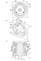
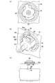
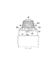
次に、第2実施形態について説明する。図5(a)〜(c)は、それぞれ、本実施形態の操作装置で、ベース部材のシャフト取付用筒部の正面図、背面斜視図、および、正面斜視図である。図6(a)、(b)は、それぞれ、本実施形態の操作装置で、ベース部材のシャフト取付用筒部の背面図、および、平面図である。図7(a)〜(c)は、それぞれ、本実施形態の操作装置の組み立て途中におけるベース部材とギアシャフトとの相対位置を示す正面図、正面斜視図、および、平面図である。図8(a)〜(c)は、それぞれ、本実施形態の操作装置の組み立て途中におけるベース部材とギアシャフトとの相対位置を示す正面図、正面斜視図、および、平面図である。図9(a)〜(c)は、それぞれ、本実施形態の操作装置の組み立て途中におけるベース部材とギアシャフトとの相対位置を示す正面図、正面斜視図、および、平面図である。図10は、本実施形態の操作装置の組み立て後におけるベース部材とギアシャフトとの相対位置を示す平面図である。
[Second Embodiment]
Next, a second embodiment will be described. FIGS. 5A to 5C are a front view, a rear perspective view, and a front perspective view, respectively, of the cylinder portion for attaching the shaft of the base member in the operating device of the present embodiment. FIGS. 6A and 6B are a rear view and a plan view, respectively, of the cylinder portion for attaching the shaft of the base member in the operating device of the present embodiment. FIGS. 7A to 7C are a front view, a front perspective view, and a plan view showing the relative positions of the base member and the gear shaft during the assembly of the operating device of the present embodiment, respectively. FIGS. 8A to 8C are a front view, a front perspective view, and a plan view showing the relative positions of the base member and the gear shaft during the assembly of the operating device of the present embodiment, respectively. FIGS. 9A to 9C are a front view, a front perspective view, and a plan view showing the relative positions of the base member and the gear shaft during the assembly of the operating device of the present embodiment, respectively. FIG. 10 is a plan view showing a relative position between the base member and the gear shaft after the operation device of the present embodiment is assembled.
本実施形態の操作装置には、第1実施形態に比べ、ギアシャフト20に代えてギアシャフト50が設けられている。ギアシャフト50は、ギアシャフト20に径方向外側へ延び出す突起部52が設けられたものである。また、ベース部材は、シャフト取付用筒部18に代えて、突起部52を案内することが可能なシャフト取付用筒部48を備えている。
The operating device of the present embodiment is provided with a
そして、本実施形態では、一時停止構造28に代えて一時停止構造58が設けられている。一時停止構造58は、シャフト取付用筒部48の内周面に設けられた第1当接面60と、ギアシャフト50に設けられた突起部52が第1当接面60に当接する溝部62とで構成され、一時停止構造58によりギアシャフト50が一時停止するときには、駆動ギア20gと従動ギア22gとが少なくとも一部嵌合状態となる。
In this embodiment, a
溝部62は、ギアシャフト挿入方向に対してクランク状となる溝部である。この溝部62は、ギアシャフト挿入方向と平行し突起部52を第1当接面60にガイドする第1溝部64と、ギアシャフト挿入方向に直交する方向に延び第1当接面60を有する第2溝部66と、ギアシャフト挿入方向と平行し突起部52が当接することにより弾性体24および弾接部材26(何れも図2参照)の挿入位置となる第2当接面70を有する第3溝部68と、によって構成されている。
The
また、本実施形態では、第2当接面70に突起部52が当接することでギアシャフトが停止する位置で、筒状保持部材20hの開口部20mに合致する切欠部18cがシャフト取付用筒部48に形成されている。
Further, in the present embodiment, the
(作用、効果)
以下、本実施形態の操作装置の組み立てについて説明する。本実施形態で操作装置を組み立てるには、まず、第1実施形態と同様、シャフト取付用筒部48にギアシャフト50を先端側から挿入するとともに、突起部52の位置を第1溝部64の位置に合わせる(図7参照)。
(Function, effect)
Hereinafter, assembly of the operating device according to the present embodiment will be described. In order to assemble the operating device in the present embodiment, first, as in the first embodiment, the
そして、ギアシャフト50を更に挿入することで突起部52を第1溝部64内に進入させる。この結果、突起部52が第1当接面60に当接して進入が停止する(図8参照。一時停止構造58による一時停止)。更に、ギアシャフト50を回転させることで突起部52を第2溝部66内に進入させる。この結果、突起部52が第2当接面70に当接して進入が停止する(図9参照)。ここで、何れの停止位置であっても、すなわち、突起部52が第1当接面60、第2当接面70の何れに当接している位置であっても、ギアシャフト50の駆動ギア20gがアーム部材22の従動ギア22gに噛み合っている。
Then, by further inserting the
そして、突起部52が第2当接面70に当接してギアシャフト50の回転が停止したときにギアの噛み合い状態が正常であることを確認して、切欠部18cから筒状保持部材20hの開口部20mに弾性体24を挿入し、更に弾接部材26を弾性体24のギアシャフト径方向外側の端部に位置させる。
Then, when the
そして、弾接部材26を筒状保持部材20hに押し込みつつギアシャフト50を更に挿入する(図10参照)。この結果、第1実施形態と同様、弾性体24が縮んだ状態で弾接部材26がシャフト取付用筒部48の節度感発生部21に当接して径方向外側への移動が規制され、しかも、嵌合爪30が嵌合部を挿通することで延出し部32の撓みがほとんど戻り、嵌合爪30が嵌合部から抜けない状態となる。
以上説明したように、本実施形態では、突起部52が溝部に沿って移動することで、駆動ギア20gと従動ギア22gとが正しく噛み合っていることを確認した上で、停止位置(一時停止の位置)からギアシャフト50を更に挿入することにより弾接部材26を節度感発生部21に当接させた状態にするので、第1実施形態と同様、操作装置の組み立て中にいわゆるギア飛びで噛み合うことが確実に防止される。
Then, the
As described above, in the present embodiment, it is confirmed that the
また、一時停止構造58は、シャフト取付用筒部48の内周面に設けられた第1当接面60と、ギアシャフト50に設けられた突起部52が第1当接面60に当接する溝部62とで構成される。従って、簡単な構成でギアシャフト50の挿入を確実に一時停止させることができる。
In the
また、溝部62は、ギアシャフト挿入方向に対してクランク状となる溝部であり、この溝部62は、ギアシャフト挿入方向と平行し突起部52を第1当接面60にガイドする第1溝部64と、ギアシャフト挿入方向に直交する方向に延び第1当接面60を有する第2溝部66と、ギアシャフト挿入方向と平行し突起部52が当接することにより弾性体24および弾接部材26の挿入位置となる第2当接面70を有する第3溝部68と、によって構成されている。従って、弾性体24および弾接部材26の挿入位置でもギアシャフト50がシャフト取付用筒部48に仮保持されているので、弾性体24と弾接部材26とを筒状保持部材20hの中に挿入し易い。
The
また、第1当接面60が一時停止構造58を構成しているので、第1実施形態で説明した鍔状の凸部34pを設けない構成にすることが可能である。
Further, since the
[第3実施形態]
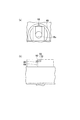
次に、第3実施形態について説明する。図11(a)〜(c)は、それぞれ、本実施形態の操作装置を組み立てる際のベース部材とギアシャフトとの相対位置を説明する側面断面図である。図12(a)、(b)は、それぞれ、本実施形態の操作装置の組み立て後の正面図、および、正面斜視図である。
[Third Embodiment]
Next, a third embodiment will be described. FIGS. 11A to 11C are side cross-sectional views illustrating the relative positions of the base member and the gear shaft when assembling the operating device of the present embodiment. 12A and 12B are a front view and a front perspective view, respectively, after assembling the operating device of the present embodiment.
本実施形態の操作装置では、第1実施形態に比べ、切欠部18cに代えて弾接部材案内部86が設けられたシャフト取付用筒部88を備えている。弾接部材案内部86は、ギアシャフト挿入方向Fに対し、シャフト取付用筒部88の中心軸側に徐々に傾斜している傾斜面86sを有する。
Compared with the first embodiment, the operating device according to the present embodiment includes a shaft mounting
本実施形態では、操作装置を組み立てる際、筒状保持部材90h(筒状保持部材20hと同様のもの)に入れた弾性体24のギアシャフト径方向外側の端部に弾接部材26を配置し、ギアシャフト挿入方向Fにギアシャフト90(ギアシャフト20と同様のもの)をそのまま押し込むことでいわゆるギア飛びで噛み合うことを防止でき、また、ギアシャフト90を一時停止しなくても済む構成にすることが可能である。
In the present embodiment, when assembling the operating device, the
10 操作装置
12 ベース部材
18 シャフト取付用筒部
18c 切欠部
18d 節度感発生用溝部
18e 縁
18s シャフト軸支部
20 ギアシャフト
20e 縁
20g 駆動ギア20
20h 筒状保持部材
20m 開口部
21 節度感発生部
22 アーム部材
24 弾性体
26 弾接部材
28 一時停止構造
30 嵌合爪
31 抵抗部
48 シャフト取付用筒部
50 ギアシャフト
52 突起部
58 一時停止構造
60 第1当接面
62 溝部
64 第1溝0部
66 第2溝部
68 第3溝部
70 第2当接面
88 シャフト取付用筒部
90 ギアシャフト
90h 筒状保持部材
DESCRIPTION OF
20h
Claims (6)
前記ギアシャフトの回転に伴い前記ギアシャフトに節度感を発生させる節度感発生部とを備え、
前記ギアシャフトには駆動ギアが設けられ、前記ベース部材に取り付けられるアーム部材に設けられた従動ギアと前記駆動ギアとが嵌合駆動する構成にされ、
前記節度感発生部が、
前記シャフト取付用筒部の内周面に対し、周方向に沿って複数設けられた軸線方向へ延びる節度感発生用溝部と、
前記ギアシャフトから半径方向へ突設された筒状保持部材と、
該筒状保持部材の内部に弾性体を介して出入自在に収容保持されることにより、前記シャフト取付用筒部の内周面の節度感発生用溝部が設けられた部分に弾性体の弾性力によって弾接可能な弾接部材とを有する操作装置において、
前記ギアシャフトを前記ベース部材へ挿入する途中で前記ギアシャフトを仮保持可能な一時停止構造を有し、
前記ギアシャフトの一時停止時には、前記駆動ギアと前記従動ギアとが少なくとも一部嵌合状態となることを特徴とする操作装置。 A gear shaft that is inserted and arranged inside a shaft mounting tube portion provided on the base member, and is rotatably held by a shaft shaft support portion with respect to the shaft mounting tube portion so as to be immovable in the axial direction;
A moderation sensation generating unit that generates a sense of moderation in the gear shaft as the gear shaft rotates,
The gear shaft is provided with a drive gear, and the driven gear provided on the arm member attached to the base member and the drive gear are configured to be fitted and driven.
The moderation generating part is
A groove portion for generating a sense of moderation extending in the axial direction provided in a plurality along the circumferential direction with respect to the inner peripheral surface of the cylindrical portion for shaft attachment,
A cylindrical holding member projecting radially from the gear shaft;
The cylindrical holding member is housed and held through an elastic body so as to be freely inserted and removed, so that the elastic force of the elastic body is provided in a portion where the moderation sensation generating groove is provided on the inner peripheral surface of the shaft mounting cylinder. In the operating device having a resilient contact member that can be resiliently contacted by,
Having a temporary stop structure capable of temporarily holding the gear shaft in the middle of inserting the gear shaft into the base member;
When the gear shaft is temporarily stopped, the driving gear and the driven gear are at least partially engaged with each other.
前記シャフト取付用筒部の内周面に設けられ、前記ギアシャフトに設けられた嵌合爪が、前記シャフト取付用筒部へ挿入中に挿入抵抗となる抵抗部であることを特徴とする請求項1に記載の操作装置。 The pause structure is
The fitting claw provided on the inner peripheral surface of the shaft mounting tube portion and provided on the gear shaft is a resistance portion that becomes an insertion resistance during insertion into the shaft mounting tube portion. Item 2. The operating device according to Item 1.
前記シャフト取付用筒部の内周面に設けられた第1当接面と、前記ギアシャフトに設けられた突起部が前記第1当接面に当接する溝部とで構成されることを特徴とする請求項1に記載の操作装置。 The pause structure is
The first abutment surface provided on the inner peripheral surface of the shaft mounting cylinder portion, and a groove portion in which a protrusion provided on the gear shaft abuts on the first abutment surface. The operating device according to claim 1.
ギアシャフト挿入方向と平行し前記突起部を前記第1当接面にガイドする第1溝部と、
ギアシャフト挿入方向に直交する方向に延び前記第1当接面を有する第2溝部と、
ギアシャフト挿入方向と平行し前記突起部が当接することにより前記弾性体および前記弾接部材の挿入位置となる第2当接面を有する第3溝部と、
によって構成されていることを特徴とする請求項4に記載の操作装置。 The groove is a groove that is crank-shaped with respect to the gear shaft insertion direction,
A first groove that is parallel to the gear shaft insertion direction and guides the protrusion to the first contact surface;
A second groove portion extending in a direction perpendicular to the gear shaft insertion direction and having the first contact surface;
A third groove portion having a second abutment surface parallel to the gear shaft insertion direction and serving as an insertion position for the elastic body and the elastic contact member by the abutment of the projection portion;
The operating device according to claim 4, comprising:
Priority Applications (1)
| Application Number | Priority Date | Filing Date | Title |
|---|---|---|---|
| JP2014009127A JP6200337B2 (en) | 2014-01-22 | 2014-01-22 | Operating device |
Applications Claiming Priority (1)
| Application Number | Priority Date | Filing Date | Title |
|---|---|---|---|
| JP2014009127A JP6200337B2 (en) | 2014-01-22 | 2014-01-22 | Operating device |
Publications (2)
| Publication Number | Publication Date |
|---|---|
| JP2015138363A true JP2015138363A (en) | 2015-07-30 |
| JP6200337B2 JP6200337B2 (en) | 2017-09-20 |
Family
ID=53769328
Family Applications (1)
| Application Number | Title | Priority Date | Filing Date |
|---|---|---|---|
| JP2014009127A Expired - Fee Related JP6200337B2 (en) | 2014-01-22 | 2014-01-22 | Operating device |
Country Status (1)
| Country | Link |
|---|---|
| JP (1) | JP6200337B2 (en) |
Cited By (1)
| Publication number | Priority date | Publication date | Assignee | Title |
|---|---|---|---|---|
| CN108768371A (en) * | 2018-07-04 | 2018-11-06 | 上海索迪龙自动化有限公司 | A kind of inductance approach switch sensor |
Citations (6)
| Publication number | Priority date | Publication date | Assignee | Title |
|---|---|---|---|---|
| JPH0533218U (en) * | 1991-09-30 | 1993-04-30 | カルソニツクツインテイー株式会社 | Bevel Gear Temporary Fixing Structure in Control Device for Automotive Air Conditioning Equipment |
| JPH0876871A (en) * | 1994-08-31 | 1996-03-22 | Zexel Corp | Assembling mechanism of control lever |
| JPH10268955A (en) * | 1997-03-25 | 1998-10-09 | Kojima Press Co Ltd | Dial type manipulator |
| JPH10301651A (en) * | 1997-04-25 | 1998-11-13 | Kojima Press Co Ltd | Dial type manipulator |
| JPH117332A (en) * | 1997-04-25 | 1999-01-12 | Kojima Press Co Ltd | Device for positioning rotation of dial shaft |
| JP2006306378A (en) * | 2005-03-31 | 2006-11-09 | Yuhshin Co Ltd | Control operating device for vehicular air conditioning |
-
2014
- 2014-01-22 JP JP2014009127A patent/JP6200337B2/en not_active Expired - Fee Related
Patent Citations (6)
| Publication number | Priority date | Publication date | Assignee | Title |
|---|---|---|---|---|
| JPH0533218U (en) * | 1991-09-30 | 1993-04-30 | カルソニツクツインテイー株式会社 | Bevel Gear Temporary Fixing Structure in Control Device for Automotive Air Conditioning Equipment |
| JPH0876871A (en) * | 1994-08-31 | 1996-03-22 | Zexel Corp | Assembling mechanism of control lever |
| JPH10268955A (en) * | 1997-03-25 | 1998-10-09 | Kojima Press Co Ltd | Dial type manipulator |
| JPH10301651A (en) * | 1997-04-25 | 1998-11-13 | Kojima Press Co Ltd | Dial type manipulator |
| JPH117332A (en) * | 1997-04-25 | 1999-01-12 | Kojima Press Co Ltd | Device for positioning rotation of dial shaft |
| JP2006306378A (en) * | 2005-03-31 | 2006-11-09 | Yuhshin Co Ltd | Control operating device for vehicular air conditioning |
Cited By (2)
| Publication number | Priority date | Publication date | Assignee | Title |
|---|---|---|---|---|
| CN108768371A (en) * | 2018-07-04 | 2018-11-06 | 上海索迪龙自动化有限公司 | A kind of inductance approach switch sensor |
| CN108768371B (en) * | 2018-07-04 | 2024-06-04 | 上海索迪龙自动化有限公司 | Inductive proximity switch sensor |
Also Published As
| Publication number | Publication date |
|---|---|
| JP6200337B2 (en) | 2017-09-20 |
Similar Documents
| Publication | Publication Date | Title |
|---|---|---|
| JP5797846B2 (en) | Shock absorber | |
| JP4358880B2 (en) | Hinge mechanism | |
| KR101611740B1 (en) | Assist grip | |
| JP6354189B2 (en) | Vehicle wiper device | |
| JP5811462B2 (en) | Turn signal switch device | |
| ES2240718T3 (en) | FIXING DEVICE FOR FIXING A BOWDEN CABLE. | |
| KR20140038851A (en) | Control apparatus for air conditioning system of vehicle | |
| JP6200337B2 (en) | Operating device | |
| JP5330965B2 (en) | Rotating body braking structure | |
| WO2011025047A1 (en) | Click type writing implement having shock-mitigating function | |
| JP5395637B2 (en) | Writing instrument | |
| JP5245621B2 (en) | Electric tool | |
| JP7464306B2 (en) | Coating film transfer tool | |
| KR20160106939A (en) | Universal type optic cable holder and optic cable connecting apparatus comprising the same | |
| JP5508231B2 (en) | Operating device | |
| JP2013242981A (en) | Rotation operation device | |
| CN107406092A (en) | Turning-bar tilting gearing | |
| JP5190443B2 (en) | 2 piece clip | |
| US9738112B2 (en) | Mechanical pencil | |
| JP6304195B2 (en) | Transmission operating mechanism of transmission | |
| KR101040313B1 (en) | Wiper Device with Variable Driving Angle | |
| JP5469346B2 (en) | Writing instrument | |
| CN112020612B (en) | Hinge device | |
| JP5996365B2 (en) | Control wire mounting structure | |
| JP2011048925A (en) | Lever switch |
Legal Events
| Date | Code | Title | Description |
|---|---|---|---|
| A621 | Written request for application examination |
Free format text: JAPANESE INTERMEDIATE CODE: A621 Effective date: 20161216 |
|
| A977 | Report on retrieval |
Free format text: JAPANESE INTERMEDIATE CODE: A971007 Effective date: 20170726 |
|
| TRDD | Decision of grant or rejection written | ||
| A01 | Written decision to grant a patent or to grant a registration (utility model) |
Free format text: JAPANESE INTERMEDIATE CODE: A01 Effective date: 20170801 |
|
| A61 | First payment of annual fees (during grant procedure) |
Free format text: JAPANESE INTERMEDIATE CODE: A61 Effective date: 20170825 |
|
| R150 | Certificate of patent or registration of utility model |
Ref document number: 6200337 Country of ref document: JP Free format text: JAPANESE INTERMEDIATE CODE: R150 |
|
| LAPS | Cancellation because of no payment of annual fees |