JP2015181908A - Measuring device, measuring system, measuring method, and electronic apparatus including measuring device - Google Patents
Measuring device, measuring system, measuring method, and electronic apparatus including measuring device Download PDFInfo
- Publication number
- JP2015181908A JP2015181908A JP2014064134A JP2014064134A JP2015181908A JP 2015181908 A JP2015181908 A JP 2015181908A JP 2014064134 A JP2014064134 A JP 2014064134A JP 2014064134 A JP2014064134 A JP 2014064134A JP 2015181908 A JP2015181908 A JP 2015181908A
- Authority
- JP
- Japan
- Prior art keywords
- unit
- pressure
- measurement
- range
- light
- Prior art date
- Legal status (The legal status is an assumption and is not a legal conclusion. Google has not performed a legal analysis and makes no representation as to the accuracy of the status listed.)
- Pending
Links
Images

Classifications
-
- A—HUMAN NECESSITIES
- A61—MEDICAL OR VETERINARY SCIENCE; HYGIENE
- A61B—DIAGNOSIS; SURGERY; IDENTIFICATION
- A61B5/00—Measuring for diagnostic purposes; Identification of persons
- A61B5/145—Measuring characteristics of blood in vivo, e.g. gas concentration or pH-value ; Measuring characteristics of body fluids or tissues, e.g. interstitial fluid or cerebral tissue
- A61B5/14532—Measuring characteristics of blood in vivo, e.g. gas concentration or pH-value ; Measuring characteristics of body fluids or tissues, e.g. interstitial fluid or cerebral tissue for measuring glucose, e.g. by tissue impedance measurement
-
- A—HUMAN NECESSITIES
- A61—MEDICAL OR VETERINARY SCIENCE; HYGIENE
- A61B—DIAGNOSIS; SURGERY; IDENTIFICATION
- A61B5/00—Measuring for diagnostic purposes; Identification of persons
- A61B5/145—Measuring characteristics of blood in vivo, e.g. gas concentration or pH-value ; Measuring characteristics of body fluids or tissues, e.g. interstitial fluid or cerebral tissue
- A61B5/1455—Measuring characteristics of blood in vivo, e.g. gas concentration or pH-value ; Measuring characteristics of body fluids or tissues, e.g. interstitial fluid or cerebral tissue using optical sensors, e.g. spectral photometrical oximeters
-
- A—HUMAN NECESSITIES
- A61—MEDICAL OR VETERINARY SCIENCE; HYGIENE
- A61B—DIAGNOSIS; SURGERY; IDENTIFICATION
- A61B5/00—Measuring for diagnostic purposes; Identification of persons
- A61B5/68—Arrangements of detecting, measuring or recording means, e.g. sensors, in relation to patient
- A61B5/6801—Arrangements of detecting, measuring or recording means, e.g. sensors, in relation to patient specially adapted to be attached to or worn on the body surface
- A61B5/6843—Monitoring or controlling sensor contact pressure
-
- A—HUMAN NECESSITIES
- A61—MEDICAL OR VETERINARY SCIENCE; HYGIENE
- A61B—DIAGNOSIS; SURGERY; IDENTIFICATION
- A61B5/00—Measuring for diagnostic purposes; Identification of persons
- A61B5/74—Details of notification to user or communication with user or patient; User input means
- A61B5/7405—Details of notification to user or communication with user or patient; User input means using sound
-
- A—HUMAN NECESSITIES
- A61—MEDICAL OR VETERINARY SCIENCE; HYGIENE
- A61B—DIAGNOSIS; SURGERY; IDENTIFICATION
- A61B5/00—Measuring for diagnostic purposes; Identification of persons
- A61B5/74—Details of notification to user or communication with user or patient; User input means
- A61B5/742—Details of notification to user or communication with user or patient; User input means using visual displays
-
- A—HUMAN NECESSITIES
- A61—MEDICAL OR VETERINARY SCIENCE; HYGIENE
- A61B—DIAGNOSIS; SURGERY; IDENTIFICATION
- A61B5/00—Measuring for diagnostic purposes; Identification of persons
- A61B5/74—Details of notification to user or communication with user or patient; User input means
- A61B5/7455—Details of notification to user or communication with user or patient; User input means characterised by tactile indication, e.g. vibration or electrical stimulation
-
- A—HUMAN NECESSITIES
- A61—MEDICAL OR VETERINARY SCIENCE; HYGIENE
- A61B—DIAGNOSIS; SURGERY; IDENTIFICATION
- A61B5/00—Measuring for diagnostic purposes; Identification of persons
- A61B5/68—Arrangements of detecting, measuring or recording means, e.g. sensors, in relation to patient
- A61B5/6801—Arrangements of detecting, measuring or recording means, e.g. sensors, in relation to patient specially adapted to be attached to or worn on the body surface
- A61B5/6813—Specially adapted to be attached to a specific body part
- A61B5/6825—Hand
- A61B5/6826—Finger
Landscapes
- Health & Medical Sciences (AREA)
- Life Sciences & Earth Sciences (AREA)
- Physics & Mathematics (AREA)
- Medical Informatics (AREA)
- Surgery (AREA)
- Engineering & Computer Science (AREA)
- Biomedical Technology (AREA)
- Heart & Thoracic Surgery (AREA)
- Biophysics (AREA)
- Molecular Biology (AREA)
- Pathology (AREA)
- Animal Behavior & Ethology (AREA)
- General Health & Medical Sciences (AREA)
- Public Health (AREA)
- Veterinary Medicine (AREA)
- Optics & Photonics (AREA)
- Emergency Medicine (AREA)
- Spectroscopy & Molecular Physics (AREA)
- Measurement Of The Respiration, Hearing Ability, Form, And Blood Characteristics Of Living Organisms (AREA)
Abstract
Description
本発明は、測定装置、測定システム、測定方法、及び測定装置を備える電子機器に関する。 The present invention relates to a measuring device, a measuring system, a measuring method, and an electronic apparatus including the measuring device.
従来、被検体の血液中に含まれる成分の濃度を測定する種々の測定方法が知られている。近年では、血液中の成分の濃度の測定において、被検体への負担を軽減するために、被検体を傷つけずに測定を行う非侵襲の測定方法に注目が集まっている。例えば、特許文献1には、生体の血液中に含まれる成分を決定する非侵襲的な方法が記載されている。 Conventionally, various measurement methods for measuring the concentration of a component contained in the blood of a subject are known. In recent years, attention has been focused on non-invasive measurement methods that perform measurement without damaging the subject in order to reduce the burden on the subject in measuring the concentration of components in blood. For example, Patent Document 1 describes a noninvasive method for determining components contained in blood of a living body.
しかしながら、特許文献1に記載の方法においては、生体の指に流れる血液を止血状態にするために、止血体を適用することが必要である。そのため、ユーザが自らの血液中に含まれる所定の成分の濃度を測定したい場合には、止血のための止血体を準備する必要があり、ユーザにとって利便性が高いものではない。 However, in the method described in Patent Document 1, it is necessary to apply a hemostatic body to bring the blood flowing through the finger of the living body into a hemostatic state. Therefore, when the user wants to measure the concentration of a predetermined component contained in his / her blood, it is necessary to prepare a hemostatic body for hemostasis, which is not convenient for the user.
かかる事情に鑑みてなされた本発明の目的は、利便性の高い測定装置、測定システム、測定方法、及び測定装置を備える電子機器を提供することにある。 The objective of this invention made | formed in view of this situation is providing the electronic device provided with the highly convenient measuring apparatus, measuring system, measuring method, and measuring apparatus.
上記課題を解決するため、本発明に係る測定装置は、
測定部に接触する被検体の血液中の所定の成分の濃度を測定する測定装置であって、
前記被検体の被検部位に光を照射する照射部と、
前記被検部位からの反射光を受光する受光部と、
前記測定部における圧力を検出する圧力検出部と、
前記圧力が第1の範囲のときの前記受光部の出力と、前記圧力が第2の範囲のときの前記受光部の出力とに基づいて、前記成分の濃度を算出する算出部とを備える。
In order to solve the above problems, a measuring apparatus according to the present invention provides:
A measuring device for measuring the concentration of a predetermined component in the blood of a subject in contact with a measuring unit,
An irradiating unit for irradiating light to a test site of the subject;
A light receiving unit for receiving reflected light from the test site;
A pressure detection unit for detecting pressure in the measurement unit;
A calculation unit that calculates the concentration of the component based on the output of the light receiving unit when the pressure is in the first range and the output of the light receiving unit when the pressure is in the second range;
また、前記圧力に関する情報を通知する通知部をさらに備えていてもよい。 Moreover, you may further provide the notification part which notifies the information regarding the said pressure.
また、前記通知部は、前記圧力が第1の範囲にあるか否かに関する情報及び前記圧力が第2の範囲にあるか否かに関する情報を通知するものであってもよい。 The notification unit may notify information regarding whether or not the pressure is in a first range and information regarding whether or not the pressure is in a second range.
また、前記照射部は、前記圧力が前記第1の範囲にあるとき及び前記圧力が前記第2の範囲にあるときに光を照射するものであってもよい。 The irradiating unit may irradiate light when the pressure is in the first range and when the pressure is in the second range.
また、前記受光部は、前記圧力が前記第1の範囲にあるとき及び前記圧力が前記第2の範囲にあるときに反射光を受光するものであってもよい。 The light receiving unit may receive reflected light when the pressure is in the first range and when the pressure is in the second range.
また、前記通知部は、音の出力、画像の表示、発光若しくは振動の出力又はこれらの任意の組合せにより前記通知を行ってもよい。 Further, the notification unit may perform the notification by outputting sound, displaying an image, outputting light or vibration, or any combination thereof.
また、本発明は上述した測定装置を備える電子機器としても実現し得る。 The present invention can also be realized as an electronic device including the above-described measuring apparatus.
また、本発明は上述した測定装置に実質的に相当するシステム及び方法としても実現し得るものであり、本発明の範囲にはこれらも包含されるものと理解されたい。 The present invention can also be realized as a system and method substantially corresponding to the measuring apparatus described above, and it should be understood that these are also included in the scope of the present invention.
例えば、本発明に係る測定システムは、
測定部に接触する被検体の血液中の所定の成分の濃度を測定する測定システムであって、
前記被検体の被検部位に光を照射する照射部、前記被検部位からの反射光を受光する受光部、及び前記測定部における圧力を検出する圧力検出部を備える測定端末と、
当該測定端末とネットワークにより接続され、前記圧力が第1の範囲のときの前記受光部の出力と、前記圧力が第2の範囲のときの前記受光部の出力とに基づいて、前記成分の濃度を算出する算出部を備えるサーバとを備える。
For example, the measurement system according to the present invention includes:
A measurement system that measures the concentration of a predetermined component in the blood of a subject in contact with a measurement unit,
A measurement terminal comprising an irradiating unit that irradiates light to a test site of the subject, a light receiving unit that receives reflected light from the test site, and a pressure detection unit that detects pressure in the measurement unit;
The concentration of the component is connected based on the output of the light receiving unit when the pressure is in the first range and the output of the light receiving unit when the pressure is in the second range. And a server that includes a calculation unit that calculates.
また、本発明に係る測定方法は、
測定部に被検体を接触させて、該被検体の血液中の所定の成分の濃度を測定するにあたり、
前記被検体の被検部位に光を照射する照射ステップと、
前記被検部位からの反射光を受光する受光ステップと、
前記測定部における圧力を検出する検出ステップと、
前記圧力が第1の範囲のときに前記受光ステップにおいて受光した前記反射光の出力と、前記圧力が第2の範囲のときに前記受光ステップにおいて受光した前記反射光の出力とに基づいて、前記成分の濃度を算出する算出ステップとを含む。
Moreover, the measuring method according to the present invention includes:
In measuring the concentration of a predetermined component in the blood of the subject by bringing the subject into contact with the measurement unit,
An irradiation step of irradiating light on a test site of the subject;
A light receiving step for receiving reflected light from the test site;
A detection step of detecting pressure in the measurement unit;
Based on the output of the reflected light received in the light receiving step when the pressure is in the first range and the output of the reflected light received in the light receiving step when the pressure is in the second range, And calculating a concentration of the component.
本発明によれば、利便性の高い測定装置、測定システム、測定方法、及び測定装置を備える電子機器を提供できる。 ADVANTAGE OF THE INVENTION According to this invention, a highly convenient measuring apparatus, a measuring system, a measuring method, and an electronic device provided with a measuring apparatus can be provided.
以下、本発明の一実施の形態について、図面を参照して詳細に説明する。 Hereinafter, an embodiment of the present invention will be described in detail with reference to the drawings.
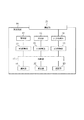
図1は、本発明の一実施の形態に係る測定装置の概略構成を示すブロック図である。測定装置10は、圧力検出部11と、照射部12と、受光部13と、D/A変換部14と、A/D変換部15及び16と、制御部17と、通知部18と、記憶部19と、算出部20と測定部21とを備える。
FIG. 1 is a block diagram showing a schematic configuration of a measuring apparatus according to an embodiment of the present invention. The
測定装置10は、生体情報として、生体(被検体)の血液中の所定の成分の濃度を測定する。ユーザが、測定装置10の測定部21に、例えば指等の被検部位を接触させると、測定装置10は、被検部位に光(測定光)を照射する。そして、測定装置10は、被検部位の毛細血管に含まれる測定対象の成分からの反射光(検出光)に基づいて、所定の成分の濃度を測定する。測定装置10は、測定対象の成分からのラマンスペクトルに基づいて、濃度の測定を行うことができる。また、測定装置10は、被検部位から受ける圧力が所定の範囲にあるときに測定を行う。ここで、所定の範囲は、所定の下限及び上限の間に含まれる範囲であってもよく、所定の値以上又は所定の値以下の範囲であってもよい。なお、所定の成分は、血液中に含まれる任意の成分とすることができるが、本明細書においては、以下、所定の成分は、例えばグルコースであり、測定装置10は、被検体の血液中のグルコース濃度を測定するものとして説明する。
The
ここで、グルコースの光の吸収スペクトルは、水分の光の吸収スペクトルと類似する。そのため、測定装置10が、被検部位を測定部21に接触させた状態において光を照射し、反射光を受光しても、反射光には、グルコースからの反射光と被検部位に含まれる水分からの反射光とが含まれる。
Here, the absorption spectrum of glucose light is similar to the absorption spectrum of moisture light. Therefore, even if the
そこで、測定装置10では、被検部位を測定部21に接触させた状態、すなわち測定部21への圧力が低い状態と、被検部位を測定部21に強く押し付けた状態、すなわち測定部21への圧力が高い状態との、2つの状態において、それぞれ第1及び第2の反射光を計測する。そして、第1及び第2の反射光の計測結果に基づいて、グルコース濃度の測定を行う。
Therefore, in the
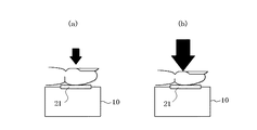
図2は、測定装置10に、被検体の被検部位である手の指を押し当てた状態を示す図である。図2(a)は、指から測定部21への圧力が低い状態を示す。このとき、毛細血管は押しつぶされていない状態(第1の状態)であるため、毛細血管中をグルコースが流れる。そのため、測定装置10が受光する第1の反射光には、グルコースからの反射光と水分からの反射光とが含まれる。
FIG. 2 is a diagram illustrating a state in which a finger of a hand, which is a test site of the subject, is pressed against the
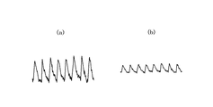
図3(a)は、第1の反射光の例を示す図である。図3(a)に示す第1の反射光には、グルコースからの反射光と水分からの反射光とが含まれる。図3(a)に示すように、反射光は、血流のリズムによる血管の収縮に合わせて、毛細血管中に含まれるグルコース及び水分からの反射を反映して、強度が変化する。 FIG. 3A is a diagram illustrating an example of the first reflected light. The first reflected light shown in FIG. 3A includes reflected light from glucose and reflected light from moisture. As shown in FIG. 3A, the intensity of the reflected light changes according to the reflection from the glucose and water contained in the capillary blood vessels in accordance with the blood vessel contraction caused by the rhythm of the blood flow.
図2(b)は、指から測定部21への圧力が高い状態を示す。このとき、圧力により被検部位の毛細血管が押しつぶされた状態(第2の状態)であり、毛細血管中をグルコースが流れない。従って、このとき測定装置10が受光する第2の反射光は、水分からの反射光であり、グルコースからの反射光は含まれていない。
FIG. 2B shows a state where the pressure from the finger to the
図3(b)は、第2の反射光の例を示す図である。図3(b)に示す第2の反射光には、水分からの反射光が含まれ、グルコースからの反射光は含まれない。図3(b)においても、図3(a)と同様に、血流のリズムによる血管の収縮に合わせて、毛細血管中に含まれる水分からの反射を反映して、反射光の強度が変化する。しかし、図3(b)においては、図3(a)と比較して、グルコースからの反射光が含まれない分だけ、反射光のピークの反射強度が低くなっている。すなわち、図3(a)と図3(b)との反射強度の差分が、グルコースからの反射光に相当する。 FIG. 3B is a diagram illustrating an example of the second reflected light. The second reflected light shown in FIG. 3B includes reflected light from moisture and does not include reflected light from glucose. In FIG. 3 (b) as well, the intensity of the reflected light changes reflecting the reflection from the water contained in the capillaries according to the contraction of the blood vessels due to the blood flow rhythm, as in FIG. 3 (a). To do. However, in FIG. 3B, compared to FIG. 3A, the reflection intensity of the peak of the reflected light is lower by the amount that does not include the reflected light from glucose. That is, the difference in reflection intensity between FIG. 3A and FIG. 3B corresponds to the reflected light from glucose.
測定装置10は、測定部21における圧力を検出し、毛細血管が第1及び第2の状態となったときに、それぞれ第1及び第2の反射光を計測する。そして、測定装置10は、このようにして計測した第1及び第2の反射光の計測結果の差分に基づき、血液中のグルコース濃度を測定する。
The measuring
再び図1を参照して説明する。圧力検出部11は、測定部21における圧力を検出する。圧力検出部11は、例えば、圧電素子により構成される。圧力検出部11は、A/D変換部15を介して制御部17に接続されており、検出した圧力信号を、A/D変換部15でデジタル信号に変換して、制御部17に送信する。
A description will be given with reference to FIG. 1 again. The
照射部12は、被検体の被検部位に光(測定光)を照射する。照射部12は、例えば、測定対象である成分を検出可能な所定の波長のレーザ光を測定光として照射するレーザ光源であり、本実施の形態においては、赤外光を照射するLD(レーザダイオード:Laser Diode)であるとして以下説明する。照射部12は、D/A変換部14を介して制御部17に接続されており、制御部17からD/A変換部14を介して受信した信号に基づいて、赤外光を照射する。
The irradiating
照射部12は、第1及び第2の状態の反射光を計測するときにのみ動作させてもよい。すなわち、照射部12は、測定部21にかかる圧力が所定の範囲にあるときに光を照射してもよい。これにより、測定を行っていないときに照射部12からレーザ光が照射されることを防ぐことができる。
The
受光部13は、照射部12が被検部位に測定光を照射することによって、被検部位から反射される反射光を受光する。そのため、被検部位に測定対象の成分が多く存在する程、受光部13が受光する反射光の強度は高くなる。受光部13は、例えば、PD(フォトダイオード:Photo Diode)により構成される。受光部13は、A/D変換部16を介して制御部17に接続されており、受光した反射光のアナログの光電変換信号をA/D変換部16でデジタル信号に変換して、制御部17に送信する。
The
制御部17は、測定装置10の各機能ブロックをはじめとして、測定装置10の全体を制御及び管理するプロセッサである。制御部17は、制御手順を規定したプログラムを実行するCPU(Central Processing Unit)等のプロセッサで構成され、かかるプログラムは、例えば記憶部19又は外部の記憶媒体等に格納される。
The
通知部18は、測定部21における圧力に関する情報を、被検体であるユーザに通知する。測定装置10は、測定部21における圧力が所定の範囲にあるときにグルコース濃度の測定を行う。そのため、圧力が所定の範囲にないときに、通知部18がユーザに通知を行うことによって、測定部21にかかる圧力を所定の範囲にするように促すことができる。
The
測定装置10は、グルコース濃度を測定する場合、上述のように第1の状態と第2の状態との2つの状態において、それぞれ第1及び第2の反射光を受光する。そのため、通知部18は、測定部21における圧力が、グルコース濃度の測定に適したそれぞれの状態であるか否かを通知できる。具体的には、通知部18は、第1の状態で第1の反射光の受光を行うときの測定部21における圧力が、グルコースが毛細血管中を流れるのに十分低い圧力の範囲(第1の範囲)内にあるか否かに関する情報を通知する。また、通知部18は、第2の状態で第2の反射光の受光を行うときの測定部21における圧力が、毛細血管が押しつぶされてグルコースが血管内を通ることができない圧力の範囲(第2の範囲)にあるか否かに関する情報を通知する。
When measuring the glucose concentration, the measuring
通知部18は、ユーザが認識可能な任意の方法により、通知を行うことができる。例えば、通知部18は、携帯電話機30が備えるスピーカからエラーを知らせるエラー音を出力できる。また、通知部18は、例えば携帯電話機30の背面に測定装置10とは別に設けた背面表示部にエラーを示すエラー画像を表示できる。また、通知部18は、例えば携帯電話機30が背面に備える発光素子を発光させることにより、エラーをユーザに通知できる。また、通知部18は、例えばバイブレータや圧電素子等の内部の振動部から振動を出力することにより、エラーを通知できる。なお、通知部18による通知方法は、上記のものに限られない。また、通知部18は、複数の任意の通知方法を組み合わせてエラーを通知してもよい。
The
また、通知部18は、測定部21における圧力が所定の範囲よりも強い場合と弱い場合とで異なるエラーを通知できる。例えば、通知部18は、振動部から振動を出力することによりエラーを通知する場合、圧力が所定の範囲よりも強い場合と弱い場合とで、異なる振動パターンでエラーを通知できる。このように異なるエラーを通知することにより、ユーザは、指で測定部21をさらに加圧すればよいのか、又は減圧すればよいのかを容易に認識でき、圧力を所定の範囲に調整しやすくなる。
The
また、通知部18は、受光部13により検出光の受光を開始及び終了したときに、ユーザに通知を行うことができる。受光開始の通知を行うことにより、ユーザは、指の押圧状態を保持すべきことを認識でき、また、受光終了の通知を行うことにより、ユーザは、指を測定部21から離してもよいということを認識できる。
Further, the
記憶部19は、半導体メモリ等で構成することができ、各種情報や測定装置10を動作させるためのプログラム等を記憶するとともに、ワークメモリとしても機能する。また、記憶部19は、第1の状態及び第2の状態でそれぞれ測定された第1及び第2の反射光の計測結果の差分と血液中のグルコース濃度との対応関係を示すテーブルデータを記憶する。テーブルデータは、予め作成され、記憶部19に記憶される。
The
算出部20は、受光部13が受光した反射光に基づいて、測定対象の成分の濃度を測定する。本実施の形態においては、算出部20は、測定部21にかかる圧力が第1の範囲のときの受光部13の出力と、圧力が第2の範囲のときの受光部13の出力とに基づいて、記憶部19に記憶されたテーブルデータを参照して、グルコースの濃度を測定する。
The
測定部21は、ユーザが生体情報を測定するために、指等の被検部位を接触させる部分である。測定部21は、例えば、板状の部材により構成できる。また、測定部21は、少なくとも測定光及び検出光に対して透明な部材により構成してもよい。測定部21は、指等と接触したとき、測定部21にかかる圧力を圧力検出部11に送信する。
The
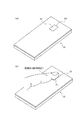
図4は、図1の測定装置10を実装した電子機器の一例を示す図である。本実施の形態において、電子機器は、例えばスマートフォン等の携帯電話機30である。図4(a)に示すように、携帯電話機30は、背面に測定装置10を備える。ユーザは、例えば図4(b)に示すように、携帯電話機30の背面の測定装置10に、被検部位である手の指の腹の部分を押し当てることにより、グルコース濃度の測定を行う。
FIG. 4 is a diagram illustrating an example of an electronic device in which the
図5は、図1の測定装置10が行うグルコース濃度の測定の処理の一例を示す図である。ここで、図5を参照して測定装置10によるグルコース濃度の測定方法について説明する。
FIG. 5 is a diagram illustrating an example of a glucose concentration measurement process performed by the
ユーザは、グルコース濃度を測定するために、まずグルコース濃度測定の専用のアプリケーションを起動させる。ユーザは、例えば携帯電話機30が備える入力部を操作してグルコース濃度測定のアプリケーションを起動できる。このとき、照射部12は、動作しておらず、測定光を照射していない。
In order to measure the glucose concentration, the user first activates a dedicated application for measuring the glucose concentration. For example, the user can start an application for measuring glucose concentration by operating an input unit included in the
ユーザは、グルコース濃度測定のアプリケーションが起動したとき、携帯電話機30の背面の測定装置10に指を押し当てる。ユーザは、まず、測定部21を押し当てる圧力が、グルコースが毛細血管中を流れるのに十分低い第1の範囲となるように指を押し当てる。制御部17は、測定部21における圧力を圧力検出部11において検出する(ステップS101)。そして、制御部17は、検出した圧力が第1の範囲内であるか否かを判断する(ステップS102)。
When the glucose concentration measurement application is activated, the user presses the finger against the
検出した圧力が第1の範囲内でないとき、すなわち、検出した圧力が第1の範囲に含まれる圧力よりも弱い又は強い場合(ステップS102のNo)、測定装置10では、通知部18が、圧力が第1の範囲内でないことを示すエラーをユーザに通知する(ステップS103)。この際、通知部18は、検出した圧力が第1の範囲に含まれるように、ユーザに対してより強い又はより弱い圧力で押圧するよう画像表示又は音声通知等で通知してもよい。
When the detected pressure is not within the first range, that is, when the detected pressure is weaker or stronger than the pressure included in the first range (No in step S102), in the
通知部18からのエラーを認識したユーザは、指から測定部21への圧力を調整する。ユーザは、圧力が第1の範囲よりも強い場合には指からの圧力を弱くし、圧力が第1の範囲よりも弱い場合には測定部21における圧力を強くすることによって、圧力を調整する。そして、圧力検出部11は、再び測定部21における圧力を検出し(ステップS101)、圧力が第1の範囲内であるか否かを判断する(ステップS102)。測定装置10は、測定部21における圧力が第1の範囲となるまで、ステップS101からステップS103を繰り返す。
The user who recognizes the error from the
制御部17は、測定部21における圧力が第1の範囲であると判断したとき、すなわち毛細血管が第1の状態となったと判断したとき(ステップS102のYes)、制御部17は、照射部12から測定光を照射させる(ステップS104)。このとき、通知部18は、圧力が第1の範囲となったことをユーザに通知してもよい。そして、受光部13が、反射光を所定時間計測する(ステップS105)。このとき受光部13は、例えば図3(a)に示すような波形の反射光を受光する。計測される反射光には、被検部位に含まれる水分及び毛細血管中を流れるグルコースからの反射光が含まれる。
When the
第1の状態の反射光の計測が終了したとき、通知部18は、計測の終了を通知する。測定の終了の通知を認識したユーザは、次に、指を測定部21に強く押し当てて、毛細血管を第2の状態とするよう調整する。具体的には、測定部21が、ステップS101と同様に、測定部21における圧力を検出する(ステップS106)。そして、測定装置10は、検出した圧力が第2の範囲内であるか否かを判断する(ステップS107)。
When the measurement of the reflected light in the first state is completed, the
検出した圧力が第2の範囲内でないとき、すなわち、検出した圧力が第2の範囲に含まれる圧力よりも弱い又は強い場合(ステップS107のNo)、測通知部18は、圧力が第2の範囲内でないことを示すエラーをユーザに通知する(ステップS108)。この際、通知部18は、検出した圧力が第2の範囲に含まれるように、ユーザに対してより強い又はより弱い圧力で押圧するよう画像表示又は音声通知等で通知してもよい。
When the detected pressure is not within the second range, that is, when the detected pressure is weaker or stronger than the pressure included in the second range (No in step S107), the
通知部18からのエラーを認識したユーザは、指から測定部21への圧力を調整する。ユーザは、圧力が第2の範囲よりも強い場合には指からの圧力を弱くし、圧力が第2の範囲よりも弱い場合には測定部21における圧力を強くすることによって、圧力を調整する。そして、圧力検出部11は、再び測定部21における圧力を検出し(ステップS106)、圧力が第2の範囲内であるか否かを判断する(ステップS107)。測定装置10は、測定部21における圧力が第2の範囲となるまで、ステップS106からステップS108を繰り返す。
The user who recognizes the error from the
制御部17は、ユーザの指からの圧力が第2の範囲であると判断したとき、すなわち毛細血管が第2の状態となったと判断したとき(ステップS107のYes)、制御部17は、照射部12から測定光を照射させる(ステップS109)。このとき、通知部18は、圧力が第2の範囲となったことをユーザに通知してもよい。そして、受光部13が、反射光を所定時間計測する(ステップS110)。このとき受光部13は、例えば図3(b)に示すような波形の反射光を受光する。計測される反射光には、被検部位に含まれる水分からの反射光が含まれるが、毛細血管が押しつぶされており、被検部位の毛細血管にはグルコースが流れないため、グルコースからの反射光は含まれない。
When the
第2の状態の反射光の計測が終了すると、通知部18は、計測の終了を通知する。そして、測定装置10は、ステップS105で計測した第1の状態の反射光の計測結果と、ステップS110で検出した第2の状態の反射光の計測結果との差分を算出する(ステップS110)。具体的には、測定装置10は、第1及び第2の状態の反射光それぞれについて、所定時間の間に受光した反射光の光電変換信号の差分を算出する。この差分は、第1の状態において毛細血管中を流れるグルコースからの反射光の光量に相当する。
When the measurement of the reflected light in the second state is completed, the
そして、測定装置10では、算出部20が、ステップS110で算出した差分に基づき、記憶部19に記憶されたテーブルデータを参照して、ユーザの血液中のグルコース濃度を測定する(ステップS112)。このテーブルデータには、例えば、予め所定の条件下で測定されたグルコース濃度とラマン散乱光の受光強度との対応テーブルが記載され、算出部20は、上記差分に基づき、当該テーブルデータを参照することにより、ユーザの血液中のグルコース濃度を測定する。
In the
ユーザは、携帯電話機30を操作して、測定されたグルコース濃度を、例えば携帯電話機30が備える表示部に表示させることにより、測定結果を知ることができる。携帯電話機30は、測定結果を表示する際に、例えば過去の測定結果との比較結果や測定結果の推移を合わせて表示してもよい。
The user can know the measurement result by operating the
このように、本実施の形態に係る測定装置10は、止血体を使用することなく、ユーザの生体情報を測定できる。そのため、ユーザは、測定装置10に指を押し当てることによって、簡便に生体情報を測定できる。このように、ユーザに対して、利便性の高い測定装置が提供される。また、ユーザの指から測定部21への圧力が適切な範囲外であるときに、通知部18が通知を行うことにより、ユーザは、圧力を適切な範囲に調整しやすくなる。そのため、ユーザは、測定に適した押圧状態を実現しやすく、生体情報の測定をスムーズに行うことができる。
Thus, the measuring
また、血液中のグルコース濃度を測定する場合、測定装置10は、被検部位に位置する毛細血管にグルコースが流れた状態と流れない状態との2つの状態における反射光を計測し、その差分に基づいて濃度を測定する。そのため、吸収スペクトルが類似する水分とグルコースとから、グルコースを抽出し、グルコース濃度を正確に測定できる。しかも、測定装置10が備える圧力検出部11と通知部18とに基づき、ユーザは、圧力を調整して上述の2つの状態を実現しやすくなる。
Moreover, when measuring the glucose concentration in blood, the measuring
また、上記実施の形態では、測定装置10は、測定対象の成分からのラマンスペクトルを用いて濃度の測定を行うとして説明したが、本発明の濃度測定方法としてはこの方法に限定されるものではなく、その他の方法を適宜利用できる。例えば、測定装置10は、レイリースペクトルに基づいて、又はラマンスペクトルとレイリースペクトルとの双方に基づいて、濃度の測定を行ってもよい。例えば、測定装置10は、レイリースペクトルを用いる場合、グルコースがおおむね波長1600nm付近の光に吸収ピークがあることを利用して、波長1600nm付近の光を照射して、反射光(散乱光)の照射光に対する吸収率を測定し、所定のテーブルデータを参照してグルコース濃度を測定してもよい。
In the above-described embodiment, the
なお、本発明は、上記実施の形態にのみ限定されるものではなく、幾多の変形または変更が可能である。例えば、各構成部、各ステップ等に含まれる機能等は論理的に矛盾しないように再配置可能であり、複数の構成部やステップ等を1つに組み合わせたり、或いは分割したりすることが可能である。 In addition, this invention is not limited only to the said embodiment, Many deformation | transformation or a change is possible. For example, the functions included in each component, each step, etc. can be rearranged so that there is no logical contradiction, and multiple components, steps, etc. can be combined or divided into one It is.
また、例えば、携帯電話機30における測定装置10の配置は、図4に示すものに限定されない。測定装置10は、例えば、携帯電話機30の背面の他の部分に配置されてもよく、また、携帯電話機30の表面又は側面等に配置されてもよい。
Further, for example, the arrangement of the measuring
また、測定装置10が搭載される電子機器は、携帯電話機30に限られない。例えば、携帯型ミュージックプレイヤ、ノートパソコン、腕時計、タブレット端末、ゲーム機などの多岐にわたる任意の電子機器に測定装置10を搭載できる。また、測定装置10は、電子機器に搭載されるものではなく、単体で使用してもよい。
Further, the electronic device on which the measuring
また、上記実施の形態において、測定装置10を使用して、血液中のグルコース濃度を測定する方法について説明したが、測定装置10は、他の所定の成分の濃度を測定できる。この場合、照射部12は、測定対象である成分を検出可能な所定の波長のレーザ光を、被検部位に照射する。
Moreover, in the said embodiment, although the measuring
また、上記実施の形態において、照射部12は、第1及び第2の状態の反射光を計測するときにのみ動作させてもよいと説明したが、同様に、受光部13は、第1及び第2の状態の反射光を計測するときにのみ動作させてもよい。すなわち、受光部13は、測定部21にかかる圧力が第1の範囲及び第2の範囲にあるときに反射光を受光してもよい。反射光を計測しないときに受光部13を停止させることにより、測定装置10(携帯電話機30)における電力消費を低減できる。
Moreover, in the said embodiment, although demonstrated that the
また、上記実施の形態において、ユーザは、グルコース濃度を計測するときに、グルコース濃度測定の専用のアプリケーションを起動するとして説明したが、本発明はこの形態に限られない。例えば、測定装置10が圧力検出部11において圧力を検出したときに、携帯電話機30は、自動的にアプリケーションを起動させて、測定装置10において圧力の測定を開始してもよい。
Moreover, in the said embodiment, when the user measured glucose concentration, it demonstrated as starting the application for exclusive use of glucose concentration measurement, However, This invention is not limited to this form. For example, when the
また、上記実施の形態では、測定部21、圧力検出部11、照射部12、受光部13及び算出部20等の全ての機能部を1つの端末上で実現するとして説明したが、本発明はこの態様に限定されるものではない。本発明は、例えば、測定部21、圧力検出部11、照射部12及び受光部13を1つの端末上で実現し、この端末と、有線若しくは無線又はこれらの組み合わせからなるネットワークで接続されたサーバ上に算出部20を配置する測定システムとして構成することが可能である。この場合、測定部21で測定された圧力に関するデータ及び受光部13で測定された反射光に関するデータは、ネットワークを介してサーバの算出部20に送信され、算出部20では、これら送信されたデータに基づいて、サーバの記憶部に記憶されたテーブルデータに基づき、グルコース濃度を測定して、端末にその測定結果を送信する。この場合、測定部21、圧力検出部11、照射部12、受光部13及び算出部20等の全ての機能部を1つの端末上で実現する場合に比べて、端末の小型化等を実現することができる。
Further, in the above embodiment, it has been described that all functional units such as the
10 測定装置
11 圧力検出部
12 照射部
13 受光部
14 D/A変換部
15、16 A/D変換部
17 制御部
18 通知部
19 記憶部
20 算出部
21 測定部
30 携帯電話機
DESCRIPTION OF
Claims (9)
前記被検体の被検部位に光を照射する照射部と、
前記被検部位からの反射光を受光する受光部と、
前記測定部における圧力を検出する圧力検出部と、
前記圧力が第1の範囲のときの前記受光部の出力と、前記圧力が第2の範囲のときの前記受光部の出力とに基づいて、前記成分の濃度を算出する算出部と
を備える測定装置。 A measuring device for measuring the concentration of a predetermined component in the blood of a subject in contact with a measuring unit,
An irradiating unit for irradiating light to a test site of the subject;
A light receiving unit for receiving reflected light from the test site;
A pressure detection unit for detecting pressure in the measurement unit;
A measurement unit comprising: a calculation unit that calculates the concentration of the component based on the output of the light receiving unit when the pressure is in the first range and the output of the light receiving unit when the pressure is in the second range. apparatus.
前記被検体の被検部位に光を照射する照射部、前記被検部位からの反射光を受光する受光部、及び前記測定部における圧力を検出する圧力検出部を備える測定端末と、
当該測定端末とネットワークにより接続され、前記圧力が第1の範囲のときの前記受光部の出力と、前記圧力が第2の範囲のときの前記受光部の出力とに基づいて、前記成分の濃度を算出する算出部を備えるサーバと
を備える測定システム。 A measurement system that measures the concentration of a predetermined component in the blood of a subject in contact with a measurement unit,
A measurement terminal comprising an irradiating unit that irradiates light to a test site of the subject, a light receiving unit that receives reflected light from the test site, and a pressure detection unit that detects pressure in the measurement unit;
The concentration of the component is connected based on the output of the light receiving unit when the pressure is in the first range and the output of the light receiving unit when the pressure is in the second range. A measurement system comprising: a server comprising a calculation unit for calculating
前記被検体の被検部位に光を照射する照射ステップと、
前記被検部位からの反射光を受光する受光ステップと、
前記測定部における圧力を検出する検出ステップと、
前記圧力が第1の範囲のときに前記受光ステップにおいて受光した前記反射光の出力と、前記圧力が第2の範囲のときに前記受光ステップにおいて受光した前記反射光の出力とに基づいて、前記成分の濃度を算出する算出ステップと
を含む測定方法。
In measuring the concentration of a predetermined component in the blood of the subject by bringing the subject into contact with the measurement unit,
An irradiation step of irradiating light on a test site of the subject;
A light receiving step for receiving reflected light from the test site;
A detection step of detecting pressure in the measurement unit;
Based on the output of the reflected light received in the light receiving step when the pressure is in the first range and the output of the reflected light received in the light receiving step when the pressure is in the second range, A measuring method including calculating a concentration of the component.
Priority Applications (4)
| Application Number | Priority Date | Filing Date | Title |
|---|---|---|---|
| JP2014064134A JP2015181908A (en) | 2014-03-26 | 2014-03-26 | Measuring device, measuring system, measuring method, and electronic apparatus including measuring device |
| PCT/JP2015/001383 WO2015146044A1 (en) | 2014-03-26 | 2015-03-12 | Measurement device, measurement system, measurement method, and electronic device provided with measurement device |
| CN201580012439.9A CN106068096B (en) | 2014-03-26 | 2015-03-12 | Measuring device, measuring system, measuring method, and electronic device provided with measuring device |
| US15/123,500 US20170071514A1 (en) | 2014-03-26 | 2015-03-12 | Measurement apparatus, measurement system, measurement method, and electronic device provided with measurement apparatus |
Applications Claiming Priority (1)
| Application Number | Priority Date | Filing Date | Title |
|---|---|---|---|
| JP2014064134A JP2015181908A (en) | 2014-03-26 | 2014-03-26 | Measuring device, measuring system, measuring method, and electronic apparatus including measuring device |
Publications (1)
| Publication Number | Publication Date |
|---|---|
| JP2015181908A true JP2015181908A (en) | 2015-10-22 |
Family
ID=54194598
Family Applications (1)
| Application Number | Title | Priority Date | Filing Date |
|---|---|---|---|
| JP2014064134A Pending JP2015181908A (en) | 2014-03-26 | 2014-03-26 | Measuring device, measuring system, measuring method, and electronic apparatus including measuring device |
Country Status (4)
| Country | Link |
|---|---|
| US (1) | US20170071514A1 (en) |
| JP (1) | JP2015181908A (en) |
| CN (1) | CN106068096B (en) |
| WO (1) | WO2015146044A1 (en) |
Families Citing this family (2)
| Publication number | Priority date | Publication date | Assignee | Title |
|---|---|---|---|---|
| KR20220030089A (en) * | 2020-09-02 | 2022-03-10 | 삼성전자주식회사 | Apparatus and method for estimating bio-information |
| CN113208586A (en) * | 2021-03-01 | 2021-08-06 | 北京理工大学 | Noninvasive blood glucose rapid diagnosis differential Raman spectroscopy system |
Citations (7)
| Publication number | Priority date | Publication date | Assignee | Title |
|---|---|---|---|---|
| JPS6392334A (en) * | 1986-10-03 | 1988-04-22 | 松下電器産業株式会社 | Non-invasive blood analyzer |
| US4883055A (en) * | 1988-03-11 | 1989-11-28 | Puritan-Bennett Corporation | Artificially induced blood pulse for use with a pulse oximeter |
| JPH11155842A (en) * | 1997-11-27 | 1999-06-15 | Horiba Ltd | Biological measuring device with constant biological contact pressure |
| JP2004298408A (en) * | 2003-03-31 | 2004-10-28 | Olympus Corp | Glucose concentration measuring apparatus |
| JP2005305091A (en) * | 2004-04-22 | 2005-11-04 | Tse:Kk | Blood sugar detecting device |
| JP2009072438A (en) * | 2007-09-21 | 2009-04-09 | Fujitsu Ltd | Fingertip proper pressing state notification method and device |
| JP2009201895A (en) * | 2008-02-29 | 2009-09-10 | Seiko Instruments Inc | Pulse wave detector and pulse wave detecting method |
Family Cites Families (8)
| Publication number | Priority date | Publication date | Assignee | Title |
|---|---|---|---|---|
| AU2245092A (en) * | 1991-12-31 | 1993-07-28 | Vivascan Corporation | Blood constituent determination based on differential spectral analysis |
| US5370114A (en) * | 1992-03-12 | 1994-12-06 | Wong; Jacob Y. | Non-invasive blood chemistry measurement by stimulated infrared relaxation emission |
| US7613488B1 (en) * | 2002-12-20 | 2009-11-03 | Niresults Inc. | Apparatus and methods for compensation of blood volume effects on NIR spectroscopic measurements of blood analytes |
| KR100580622B1 (en) * | 2003-03-19 | 2006-05-16 | 삼성전자주식회사 | Non-invasive blood component measurement method and apparatus |
| US20080306363A1 (en) * | 2005-01-06 | 2008-12-11 | Lightouch Medical, Inc. | Specialized Human Servo Device And Process For Tissue Modulation Of Human Fingerprints |
| CN101466307A (en) * | 2006-06-12 | 2009-06-24 | 三菱电机株式会社 | System and method for measuring component concentration |
| US20090204009A1 (en) * | 2008-02-07 | 2009-08-13 | Los Alamos National Security | Medical device system and related methods for diagnosing abnormal medical conditions based on in-vivo optical properties of tissue |
| US20130060098A1 (en) * | 2009-12-23 | 2013-03-07 | Delta, Dansk Elektronik, Lys Og Akustik | Monitoring device |
-
2014
- 2014-03-26 JP JP2014064134A patent/JP2015181908A/en active Pending
-
2015
- 2015-03-12 WO PCT/JP2015/001383 patent/WO2015146044A1/en not_active Ceased
- 2015-03-12 CN CN201580012439.9A patent/CN106068096B/en not_active Expired - Fee Related
- 2015-03-12 US US15/123,500 patent/US20170071514A1/en not_active Abandoned
Patent Citations (7)
| Publication number | Priority date | Publication date | Assignee | Title |
|---|---|---|---|---|
| JPS6392334A (en) * | 1986-10-03 | 1988-04-22 | 松下電器産業株式会社 | Non-invasive blood analyzer |
| US4883055A (en) * | 1988-03-11 | 1989-11-28 | Puritan-Bennett Corporation | Artificially induced blood pulse for use with a pulse oximeter |
| JPH11155842A (en) * | 1997-11-27 | 1999-06-15 | Horiba Ltd | Biological measuring device with constant biological contact pressure |
| JP2004298408A (en) * | 2003-03-31 | 2004-10-28 | Olympus Corp | Glucose concentration measuring apparatus |
| JP2005305091A (en) * | 2004-04-22 | 2005-11-04 | Tse:Kk | Blood sugar detecting device |
| JP2009072438A (en) * | 2007-09-21 | 2009-04-09 | Fujitsu Ltd | Fingertip proper pressing state notification method and device |
| JP2009201895A (en) * | 2008-02-29 | 2009-09-10 | Seiko Instruments Inc | Pulse wave detector and pulse wave detecting method |
Also Published As
| Publication number | Publication date |
|---|---|
| US20170071514A1 (en) | 2017-03-16 |
| CN106068096B (en) | 2019-10-08 |
| CN106068096A (en) | 2016-11-02 |
| WO2015146044A1 (en) | 2015-10-01 |
Similar Documents
| Publication | Publication Date | Title |
|---|---|---|
| US9737218B2 (en) | Blood pressure measurement device, electronic device, and blood pressure measurement method | |
| KR102531994B1 (en) | Apparatus and method for measuring biological components | |
| JP2016146958A (en) | Blood pressure measuring device and blood pressure measuring method | |
| KR20160086710A (en) | Method and apparatus for simultaneously detecting body surface pressure and blood volume | |
| JP2005028157A5 (en) | ||
| CN109805888B (en) | Spectrometer, method for controlling the output gain of the spectrometer, and device and method for measuring biological information | |
| KR20190035234A (en) | Apparatus for estimating biological component and operating method thereof | |
| US20170319084A1 (en) | Measuring apparatus and measuring method | |
| JP2015181908A (en) | Measuring device, measuring system, measuring method, and electronic apparatus including measuring device | |
| US7805184B2 (en) | Portable body fat measurement device and optical sensor module of the device | |
| JP6216303B2 (en) | Measuring apparatus and measuring method | |
| JP2016026518A (en) | Measuring apparatus and measuring method | |
| KR20200032319A (en) | Blood pressure measurement apparatus and method | |
| CN113243911B (en) | A detection method, device, device, electronic equipment and storage medium | |
| JP2016112042A (en) | Bio-information obtaining device, bio-information obtaining method and electronic apparatus | |
| JP7024261B2 (en) | Optical measuring device and optical measuring program | |
| WO2015194162A1 (en) | Measurement device and measurement method | |
| WO2015198584A1 (en) | Measurement device and measurement method | |
| JP2015208342A (en) | MEASUREMENT DEVICE, MEASUREMENT SYSTEM, MEASUREMENT METHOD, AND ELECTRONIC DEVICE PROVIDED WITH MEASUREMENT DEVICE | |
| CN114271802B (en) | Biological information measuring apparatus | |
| JP2019171225A (en) | Measuring device and measuring method | |
| JP2016047120A (en) | Measuring apparatus and measuring method | |
| JP2016067405A (en) | Measuring apparatus, measuring method, and electronic apparatus including measuring apparatus | |
| JP2016030095A (en) | Measuring apparatus and measuring method | |
| JP2016007504A (en) | MEASUREMENT DEVICE, MEASUREMENT SYSTEM, MEASUREMENT METHOD, AND ELECTRONIC DEVICE PROVIDED WITH MEASUREMENT DEVICE |
Legal Events
| Date | Code | Title | Description |
|---|---|---|---|
| A621 | Written request for application examination |
Free format text: JAPANESE INTERMEDIATE CODE: A621 Effective date: 20160713 |
|
| A131 | Notification of reasons for refusal |
Free format text: JAPANESE INTERMEDIATE CODE: A131 Effective date: 20170711 |
|
| A521 | Request for written amendment filed |
Free format text: JAPANESE INTERMEDIATE CODE: A523 Effective date: 20170904 |
|
| A131 | Notification of reasons for refusal |
Free format text: JAPANESE INTERMEDIATE CODE: A131 Effective date: 20180213 |
|
| A521 | Request for written amendment filed |
Free format text: JAPANESE INTERMEDIATE CODE: A523 Effective date: 20180409 |
|
| A02 | Decision of refusal |
Free format text: JAPANESE INTERMEDIATE CODE: A02 Effective date: 20180904 |
|
| A521 | Request for written amendment filed |
Free format text: JAPANESE INTERMEDIATE CODE: A523 Effective date: 20180920 |
|
| A911 | Transfer to examiner for re-examination before appeal (zenchi) |
Free format text: JAPANESE INTERMEDIATE CODE: A911 Effective date: 20181001 |
|
| A912 | Re-examination (zenchi) completed and case transferred to appeal board |
Free format text: JAPANESE INTERMEDIATE CODE: A912 Effective date: 20181019 |
|
| A521 | Request for written amendment filed |
Free format text: JAPANESE INTERMEDIATE CODE: A523 Effective date: 20190618 |