JP2015190840A - sludge container - Google Patents
sludge container Download PDFInfo
- Publication number
- JP2015190840A JP2015190840A JP2014067953A JP2014067953A JP2015190840A JP 2015190840 A JP2015190840 A JP 2015190840A JP 2014067953 A JP2014067953 A JP 2014067953A JP 2014067953 A JP2014067953 A JP 2014067953A JP 2015190840 A JP2015190840 A JP 2015190840A
- Authority
- JP
- Japan
- Prior art keywords
- container
- sludge
- heat exchange
- solid content
- container body
- Prior art date
- Legal status (The legal status is an assumption and is not a legal conclusion. Google has not performed a legal analysis and makes no representation as to the accuracy of the status listed.)
- Granted
Links
Images

Landscapes
- Fertilizing (AREA)
- Packaging Of Annular Or Rod-Shaped Articles, Wearing Apparel, Cassettes, Or The Like (AREA)
Abstract
【課題】容器内に沈殿したスラッジにおける固形分の冷却効果を高め、容器の構造健全性を向上させることが可能となるスラッジ容器を提供する。
【解決手段】本発明に係るスラッジ容器は、スラッジが導入される容器本体10と、該容器本体10内に設けられて、前記固形分200が沈殿して収容される受け部11と、該容器本体10内における前記受け部11の上方の上空間S1と該容器本体10内における前記受け部11の下方の下空間S2とを連通させる流路12と、前記受け部11を上下方向に貫通して、下端が前記下空間S2に開口するとともに、上端が前記上空間S1に開口する熱交換管13とを備える。
【選択図】図2The present invention provides a sludge container that can enhance the cooling effect of the solid content of sludge precipitated in the container and improve the structural integrity of the container.
A sludge container according to the present invention includes a container main body 10 into which sludge is introduced, a receiving portion 11 provided in the container main body 10 in which the solid content 200 is precipitated, and the container. A flow path 12 that allows communication between the upper space S1 above the receiving portion 11 in the main body 10 and the lower space S2 below the receiving portion 11 in the container main body 10, and the receiving portion 11 penetrates in the vertical direction. And a heat exchange tube 13 having a lower end opened to the lower space S2 and an upper end opened to the upper space S1.
[Selection] Figure 2
Description
本発明は、発熱性のあるスラッジを貯蔵する容器の冷却機能に関する。 The present invention relates to a cooling function of a container for storing exothermic sludge.
例えば原子力施設では、処理の過程で放射性廃棄物等の発熱性を有したスラッジが発生する。このようなスラッジを安定して貯蔵するための容器として、スラッジ容器が用いられる。 For example, in a nuclear facility, sludge having a heat generating property such as radioactive waste is generated in the process. A sludge container is used as a container for stably storing such sludge.
放射性廃棄物のようなスラッジは、時間とともにスラッジと水が分離し、容器の底部に固形分が沈殿する。沈殿した固形分は徐々に固着して水の割合が減少し、固形分の発熱により発生した熱を逃がしにくくなる。
容器の底部に発熱性のある固形分が沈殿して発熱することにより、沈殿した固形分の温度が上昇し、その結果、固形分と接触する容器も加熱される。これにより、容器が劣化してしまう場合がある。
このような問題を回避するために、発熱性のある物質を耐熱材で受け止め、冷却水を注水して冷却を行う方法が提案されている(例えば特許文献1)。
Sludge such as radioactive waste separates sludge and water with time, and solids settle at the bottom of the container. The precipitated solid content is gradually fixed and the ratio of water is reduced, making it difficult to release the heat generated by the heat generation of the solid content.
When the exothermic solid content precipitates at the bottom of the container and generates heat, the temperature of the precipitated solid content increases, and as a result, the container in contact with the solid content is also heated. Thereby, a container may deteriorate.
In order to avoid such a problem, a method has been proposed in which a heat-generating material is received by a heat-resistant material, and cooling is performed by injecting cooling water (for example, Patent Document 1).
特許文献1に記載の冷却方法では、熱伝導率の低いスラッジの場合、または、容器の底部に沈殿した固形分の量が多い場合には、沈殿した固形分の中心部にまで冷却水の冷却効果が届かず、固形分の熱を十分に逃がすことができない可能性がある。この結果、固形分により容器が加熱され、やはり容器に劣化が生じてしまうことがある。
本発明は、容器内に沈殿したスラッジにおける固形分の冷却効果を高めることが可能となるスラッジ容器を提供する。
In the cooling method described in
The present invention provides a sludge container that can enhance the cooling effect of solid content in sludge precipitated in the container.
上記課題を解決するために、本発明は以下の手段を採用している。
本発明に係るスラッジ容器は、スラッジが導入される容器本体と、該容器本体内に設けられて、前記固形分が沈殿して収容される受け部と、該容器本体内における前記受け部の上方の上空間と該容器本体内における前記受け部の下方の下空間とを連通させる流路と、前記受け部を上下方向に貫通して、下端が前記下空間に開口するとともに、上端が前記上空間に開口する熱交換管とを備える。
In order to solve the above problems, the present invention employs the following means.
A sludge container according to the present invention includes a container main body into which sludge is introduced, a receiving part that is provided in the container main body, and in which the solid content is settled and accommodated, and above the receiving part in the container main body A flow path that communicates the upper space of the container body with the lower space below the receiving portion in the container body, the receiving portion is vertically penetrated, the lower end opens into the lower space, and the upper end is the upper And a heat exchange tube that opens into the space.
このようなスラッジ容器では、受け部が容器本体の底部に向かって沈降する固形分を受け止める。これにより、容器本体に接触する固形分の量が減少し、固形分の発熱により容器本体が直接的に熱せられることが抑制される。
また、容器本体内の上空間と下空間とを水が流動可能となり、さらに沈殿した固形分の内部を貫通するように上区間とした空間とを連通させる熱交換管を介して、固形分と、熱交換管の内部を流通する水との間で熱交換が行われる。これにより、固形分は冷却され、熱交換管の内部を通る水は温められる。この結果、熱交換管の内部の水は上空間に向かって上昇し、熱交換管の内部から上昇した水によって押された上空間の水は、容器本体の内壁に沿って流路に流入し、流路より下空間へ流通する。これにより、容器本体内には定常的な冷却流が形成される。
In such a sludge container, the receiving part receives the solid content that settles toward the bottom of the container body. Thereby, the quantity of the solid content which contacts a container main body reduces, and it is suppressed that a container main body is heated directly by heat_generation | fever of a solid content.
In addition, the water can flow through the upper space and the lower space in the container body, and further through the heat exchange pipe that communicates with the space defined as the upper section so as to penetrate the inside of the precipitated solid content. Then, heat exchange is performed with water flowing through the heat exchange pipe. Thereby, solid content is cooled and the water which passes the inside of a heat exchange pipe | tube is warmed. As a result, the water inside the heat exchange pipe rises toward the upper space, and the water in the upper space pushed by the water raised from the inside of the heat exchange pipe flows into the flow path along the inner wall of the container body. Circulates in the lower space from the flow path. Thereby, a steady cooling flow is formed in the container body.
また、本発明に係るスラッジ容器において、前記流路は、前記下空間の最下部における上下方向の高さが、他の位置の上下方向の高さよりも大きく形成されていてもよい。 Moreover, the sludge container which concerns on this invention WHEREIN: The said flow path may be formed so that the height of the up-down direction in the lowest part of the said lower space is larger than the height of the up-down direction of another position.
このように流路が形成されることにより、固形分が流路を経由して水とともに容器本体の下空間へ流入し、容器本体の底部に沈殿したとしても、下空間の最下部における上下方向の高さ十分に確保される。このため、沈殿した固形分により流路が塞がれ、容器本体内の定常的な冷却流が妨げられることを抑制することが可能となる。 By forming the flow path in this way, even if solid content flows into the lower space of the container body together with water via the flow path and settles at the bottom of the container body, the vertical direction in the lowermost portion of the lower space The height is secured sufficiently. For this reason, it becomes possible to suppress that the flow path is blocked by the precipitated solid content and the steady cooling flow in the container body is hindered.
また、本発明に係るスラッジ容器は、前記熱交換管の外周面または内周面の少なくとも一方に設けられたフィンを備えてもよい。 The sludge container according to the present invention may include fins provided on at least one of the outer peripheral surface and the inner peripheral surface of the heat exchange pipe.
このように熱交換管にフィンが設けられていることにより、熱交換管の表面積が大きくなる。これにより、熱交換管を介して行われる、熱交換管の内部を流通する水と、固形分との熱交換の効率が向上する。この結果、容器本体内の冷却流の形成を促進し、固形分の冷却効果を高めることが可能となる。 Since the fins are provided in the heat exchange tube in this way, the surface area of the heat exchange tube is increased. Thereby, the efficiency of the heat exchange with the water which distribute | circulates the inside of a heat exchange pipe | tube performed via a heat exchange pipe | tube, and solid content improves. As a result, it is possible to promote the formation of a cooling flow in the container body and enhance the cooling effect of the solid content.
また、本発明に係るスラッジ容器は、前記流路が前記受け部と前記容器本体により画成されていてもよい。 In the sludge container according to the present invention, the flow path may be defined by the receiving portion and the container main body.
このように流路が受け部と容器本体により画成されることにより、流路を形成するための管等を容器本体内または容器本体外に設ける必要がなくなり、スラッジ容器の構成を簡易なものとすることができる。この結果、スラッジ容器をコンパクトにすることが可能となり、設置面積が限られる施設においても設置が可能となる。また、スラッジ容器を製造する際に部品点数を減らし、生産コストを低減させることが可能となる。 In this way, the flow path is defined by the receiving portion and the container main body, so that it is not necessary to provide a pipe or the like for forming the flow path inside or outside the container main body, and the configuration of the sludge container is simplified. It can be. As a result, the sludge container can be made compact, and installation is possible even in facilities where the installation area is limited. Moreover, when manufacturing a sludge container, it becomes possible to reduce a number of parts and to reduce production cost.
本発明に係るスラッジ容器によれば、スラッジにおける固形分の冷却効果を高め、容器の構造健全性を向上させることが可能となる。 According to the sludge container according to the present invention, it is possible to enhance the cooling effect of the solid content in the sludge and improve the structural soundness of the container.
〔第一実施形態〕
以下、本発明の第一実施形態に係るスラッジ容器100Aについて、図1および図2を参照して説明する。
スラッジ容器100Aは、例えば放射性廃棄物等のスラッジを貯蔵するための容器である。
[First embodiment]
Hereinafter, the
The
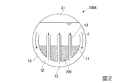
スラッジ容器100Aは、スラッジが導入される容器本体10と、容器本体10内に設けられ、スラッジにおける固形分200が沈殿して収容される受け部11と、容器本体10内における受け部11の上方の上空間S1および下方の下空間S2を連通させる流路12と、受け部11を上下方向に貫通する熱交換管13を備える。
The
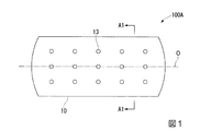
図1に示すように、容器本体10は、軸線Oに沿って延びて両端が閉塞された円筒状に形成され、軸線Oが設置面と略水平となるように配置されている。
本実施形態において、容器本体10は円筒状に形成されているが、この形状に限られることはなく、例えば多角形の角筒状に形成されてもよい。また、本実施形態において、容器本体10は密閉型としているが、導入するスラッジの種類に応じて、例えば容器本体10の上方が開口されていてもよい。
As shown in FIG. 1, the
In the present embodiment, the
受け部11は、図2に示すように、容器本体10内において、容器本体10の内周に沿って湾曲し、軸線O軸線Oに沿って延びる半円筒状に形成された、板状の部材である。受け部11は、円弧側を容器本体10の下方に向け、図示しない脚部に支持されて容器本体10の内周面から空間を隔てて設けられる。容器本体10の内部には、受け部11によって、受け部11の上方の上空間S1と、受け部11の下方の下空間S2が画成される。
本実施形態において、受け部11は半円筒状に形成されているが、この形状に限られることはなく、例えば、半角筒状に形成されてもよい。
As shown in FIG. 2, the
In the present embodiment, the
流路12は、容器本体10内の上空間S1と下空間S2を連通させて、スラッジ内の水が流通する経路である。本実施形態においては、図2に示すように、容器本体10と受け部11により画成された下空間S2が流路12として機能する。
The
熱交換管13は、図2に示すように、受け部11を上下方向に貫通し、下端が下空間S2に開口するとともに、上端が上空間S1に開口する、筒状の部材である。
また、図1に示すように、熱交換管13は、容器本体10内に間隔をあけて複数設けられている。
As shown in FIG. 2, the
As shown in FIG. 1, a plurality of
上述の容器本体10においては、スラッジにおける固形分200が時間とともに水と分離し、容器本体10の下方に沈降する。沈降した固形分200は、受け部11の上に沈殿する。これにより、固形分200が容器本体10の底部に沈殿することが抑制され、容器本体10に接触する固形分200の量が減少する。この結果、固形分200が発熱しても、容器本体10を加熱することがなく、容器本体10の構造健全性が保たれ、容器本体10の破損等を抑制することができる。
In the container
また、熱交換管13は、受け部11を上下方向に貫通するとともに、受け部11に沈殿した固形分200を上下方向に貫通する。この構成により、熱交換管13と接触する固形分200と、熱交換管13の内部の水との間で、熱交換管13を介して熱交換が行われる。より詳細に説明すると、固形分200は、熱交換管13を介して熱交換管13の内部の水により冷却される。同時に、熱交換管13の内部の水は、熱交換管13を介して固形分200の熱により温められる。
Further, the
温められた熱交換管13内部の水は、熱交換管13の上端に向かって上昇する。熱交換管13の内部を上昇した水は、熱交換管13の上端の開口部から容器本体10の上空間S1に流入して上空間S1内の水を押し出す。押し出された上空間S1内の水は、容器本体10の側面に沿って、流路12に流入し、さらに容器本体10の下空間S2へ向かって流れる。下空間S2に流入した水は、熱交換管13の下端の開口部から再び熱交換管13に流入する。このように、容器本体10の内部を水が循環するようになり、熱交換管13において温められた水は、循環する内に再び冷却され、図2に示すような定常的な冷却流Fが形成される。
The warmed water in the
この冷却流Fにより、熱交換管13における熱交換を効果的に行うことが可能となる。この結果、固形分200の熱を効率的に逃がすことができ、固形分200の温度の上昇を抑えることが可能となる。これにより、容器本体10が加熱されることが抑制される。従って、容器本体10の構造健全性が保たれ、容器本体10の破損等を抑制することができる。
With this cooling flow F, heat exchange in the
さらに、固形分200の熱伝導率が低い場合や、受け部11に沈殿した固形分200の量が多い場合であっても、複数の熱交換管13が、沈殿した固形分200の内部を貫通するように設けられていることにより、固形分200と接触する熱交換管13の総表面積が大きくなるため、熱交換管33を介して行われる、熱交換管13の内部を流通する水と、固形分200との熱交換の効果を高めることが可能となる。この結果、容器本体10内の冷却流Fの形成を促進し、固形分200の冷却効果を高めることが可能となる。
Furthermore, even when the
本実施形態においては、容器本体10および受け部11により画成された下空間S2を流路12として機能させている。これにより、スラッジ容器100Aの構成を簡易なものとすることができる。また、スラッジ容器100Aの外部に流路を設ける場合に比べて、スラッジ容器100Aをコンパクトにすることが可能となり、設置面積が限られる施設においても使用可能となる。また、スラッジ容器100Aを製造する際に部品点数を減らし、生産コストを低減させることが可能となる。
In the present embodiment, the lower space S <b> 2 defined by the container
しかしながら、流路12の構成は、この構成に限られることはない。例えば、設置面積に余裕のある施設等では、容器本体10内の水が、容器本体10の上空間S1から容器本体10の外部に向かって流出し、容器本体10の外部より容器本体の下空間S2に向かって再び流入するように延出された管を設けてもよい。また、容器本体10の外部に延出された管および管の内部を流通する水を冷却するための装置を設けてもよい。この構成により、固形分200の冷却効果をさらに高めることが可能となる。
However, the configuration of the
〔第二実施形態〕
次に、本発明の第二実施形態に係るスラッジ容器100Bについて説明する。
第一実施形態と共通の構成要素には同一の符号を付して詳細説明を省略する。
[Second Embodiment]
Next, the
Constituent elements common to the first embodiment are denoted by the same reference numerals, and detailed description thereof is omitted.
本実施形態は、スラッジ容器100Bが備える流路22が第一実施形態とは異なっている。
本実施形態においては、図3に示すように、容器本体10と受け部11により画成された下空間S2が流路22として機能する。本実施形態においては、容器本体10の内周面と受け部11の下方面との距離が、容器本体10の下方に向かうに従って広くなるように容器本体10と受け部11を配置している。これにより、流路22として機能する容器本体10の下空間S2は、最下部における上下方向の高さが、下空間S2の他の位置の上下方向の高さよりも大きくなる。つまり、流路22は、容器本体10の最下部において最も上下方向の高さが大きくなるように形成されている。
In the present embodiment, the
In the present embodiment, as shown in FIG. 3, the lower space S <b> 2 defined by the container
上述の流路22の構成によれば、固形分200が流路を経由して水とともに容器本体10の下空間S2に流入し、容器本体10の底部に沈殿したとしても、流路22の容器本体10の最下部における上下方向の高さが十分に確保されているため、固形分200により流路22が塞がれ、容器本体10内の定常的な冷却流Fが妨げられることを抑制することが可能となる。
According to the configuration of the
本実施形態においては、容器本体10の内周面と受け部11の下方面との距離が、容器本体10の下方に向かうに従って広くなるように容器本体10と受け部11を配置する構成としているが、この構成に限られることはない。例えば、容器本体10の底部に凹部を設け、該凹部に固形分200が沈殿するようにすることで、上述の構成と同様に、沈殿した固形分200により流路22が塞がれることを抑制する効果を得ることができる。
In the present embodiment, the
〔第三実施形態〕
次に、本発明の第三実施形態に係るスラッジ容器100Cについて説明する。
第一実施形態および第二実施形態と共通の構成要素には同一の符号を付して詳細説明を省略する。
[Third embodiment]
Next, the sludge container 100C according to the third embodiment of the present invention will be described.
Constituent elements common to the first embodiment and the second embodiment are denoted by the same reference numerals, and detailed description thereof is omitted.
本実施形態は、スラッジ容器100Cが備える熱交換管33が第一実施形態および第二実施形態とは異なっている。
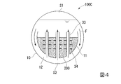
本実施形態において、図4に示すように、熱交換管33の外周面に該熱交換管33の外方に向かって突出するフィン34が設けられている。本実施形態では、フィン34は、熱交換管33の外周面から該外周面の全周にわたって円形に張り出す鍔状をなしている。そして、当該フィン34が上下方向、即ち、熱交換管33の延在方向に間隔をあけて複数設けられている。
In the present embodiment, the heat exchange pipe 33 provided in the sludge container 100C is different from the first embodiment and the second embodiment.
In the present embodiment, as shown in FIG. 4,
上述の熱交換管33の構成によれば、熱交換管33の外周面に複数のフィン34が設けられていることにより、沈殿した固形分200と接触する熱交換管33の総表面積がさらに大きくなる。これにより、熱交換管33を介して行われる、熱交換管33の内部を流通する水と、固形分200との熱交換の効果が向上する。この結果、容器本体10内の冷却流Fの形成を促進し、固形分200の冷却効果を高めることが可能となる。
According to the configuration of the heat exchange pipe 33 described above, the plurality of
本実施形態においては、複数のフィン34は、板状に形成され、熱交換管33の外周面に設けられる構成としているが、この構成に限られることはない。例えば、複数のフィン34は円柱状に形成されていてもよい。さらに、例えばフィン34が、熱交換管33の延在方向に向かうに従って周方向に捩じれる螺旋状に形成されていてもよい。
また、複数のフィン34は、熱交換管33の内周面に設けられてもよい。複数のフィン34を熱交換管33の内周面に設けることにより、熱交換管33の内部を流通する水と接触する熱交換管33の総表面積が大きくなる。この構成によっても、熱交換管33を介して行われる、熱交換管33の内部を流通する水と、固形分200との熱交換の効果が向上する。この結果、容器本体10内の冷却流Fの形成を促進し、固形分200の冷却効果を高めることが可能となる。
In the present embodiment, the plurality of
Further, the plurality of
以上、本発明の実施形態について詳細に説明したが、本発明の技術的思想を逸脱しない限り、これらに限定されることはなく、多少の設計変更等も可能である。
例えば、本発明の実施形態において、スラッジ容器100A〜100Cは、放射性廃棄物のスラッジを貯蔵するための容器であるとしたが、屎尿等、他のスラッジを貯蔵するために用いられてもよい。
As mentioned above, although embodiment of this invention was described in detail, unless it deviates from the technical idea of this invention, it is not limited to these, A some design change etc. are possible.
For example, in the embodiment of the present invention, the
また、スラッジ容器100A〜100Cは、容器本体10内にスラッジの沈澱を抑制するための攪拌手段を備えていてもよい。
Moreover, the
100A、100B、100C…スラッジ容器 10…容器本体 11…受け部 12、22…流路 13、33…熱交換管 34…フィン 200…固形分 S1…容器本体の上空間 S2…容器本体の下空間 O…軸線 F…冷却流
100A, 100B, 100C ...
Claims (4)
該容器本体内に設けられて、前記スラッジにおける固形分が沈殿して収容される受け部と、
該容器本体内における前記受け部の上方の上空間と該容器本体内における前記受け部の下方の下空間とを連通させる流路と、
前記受け部を上下方向に貫通して、下端が前記下空間に開口するとともに、上端が前記上空間に開口する熱交換管と、
を備えるスラッジ容器。 A container body into which sludge is introduced;
A receiving portion provided in the container body, in which the solid content in the sludge is precipitated and accommodated;
A flow path for communicating the upper space above the receiving part in the container body with the lower space below the receiving part in the container body;
A heat exchange pipe that penetrates the receiving portion in the vertical direction and has a lower end opened in the lower space and an upper end opened in the upper space;
A sludge container.
前記下空間の最下部における上下方向の高さが、他の位置の上下方向の高さよりも大きく形成されている、
請求項1に記載のスラッジ容器。 The flow path is
The vertical height at the bottom of the lower space is formed larger than the vertical height of other positions,
The sludge container according to claim 1.
請求項1又は2に記載のスラッジ容器。 Comprising fins provided on at least one of the outer peripheral surface and the inner peripheral surface of the heat exchange pipe,
The sludge container according to claim 1 or 2.
請求項1から3のいずれか一項に記載のスラッジ容器。 The flow path is defined by the receiving portion and the container body;
The sludge container according to any one of claims 1 to 3.
Priority Applications (1)
| Application Number | Priority Date | Filing Date | Title |
|---|---|---|---|
| JP2014067953A JP6403305B2 (en) | 2014-03-28 | 2014-03-28 | Sludge container |
Applications Claiming Priority (1)
| Application Number | Priority Date | Filing Date | Title |
|---|---|---|---|
| JP2014067953A JP6403305B2 (en) | 2014-03-28 | 2014-03-28 | Sludge container |
Publications (2)
| Publication Number | Publication Date |
|---|---|
| JP2015190840A true JP2015190840A (en) | 2015-11-02 |
| JP6403305B2 JP6403305B2 (en) | 2018-10-10 |
Family
ID=54425441
Family Applications (1)
| Application Number | Title | Priority Date | Filing Date |
|---|---|---|---|
| JP2014067953A Active JP6403305B2 (en) | 2014-03-28 | 2014-03-28 | Sludge container |
Country Status (1)
| Country | Link |
|---|---|
| JP (1) | JP6403305B2 (en) |
Citations (8)
| Publication number | Priority date | Publication date | Assignee | Title |
|---|---|---|---|---|
| JPS5863899A (en) * | 1981-10-14 | 1983-04-15 | 株式会社日立製作所 | Radioactive liquid waste tank |
| JPS5879568U (en) * | 1981-11-26 | 1983-05-30 | 三菱重工業株式会社 | suspension storage tank |
| JPS6191200U (en) * | 1984-11-19 | 1986-06-13 | ||
| JPH10160897A (en) * | 1996-11-29 | 1998-06-19 | Ishikawajima Harima Heavy Ind Co Ltd | Heat dissipation structure of vitrified body |
| JPH1160201A (en) * | 1997-08-04 | 1999-03-02 | Sanritsuku:Kk | Storage container for hydrogen storage alloy |
| JP2003021694A (en) * | 2001-07-06 | 2003-01-24 | Mitsubishi Heavy Ind Ltd | Water management method |
| JP2006162339A (en) * | 2004-12-03 | 2006-06-22 | Mitsubishi Heavy Ind Ltd | Heat exchanger and nuclear reactor |
| US20130001224A1 (en) * | 2011-06-28 | 2013-01-03 | Alton Payne | Storage tank |
-
2014
- 2014-03-28 JP JP2014067953A patent/JP6403305B2/en active Active
Patent Citations (8)
| Publication number | Priority date | Publication date | Assignee | Title |
|---|---|---|---|---|
| JPS5863899A (en) * | 1981-10-14 | 1983-04-15 | 株式会社日立製作所 | Radioactive liquid waste tank |
| JPS5879568U (en) * | 1981-11-26 | 1983-05-30 | 三菱重工業株式会社 | suspension storage tank |
| JPS6191200U (en) * | 1984-11-19 | 1986-06-13 | ||
| JPH10160897A (en) * | 1996-11-29 | 1998-06-19 | Ishikawajima Harima Heavy Ind Co Ltd | Heat dissipation structure of vitrified body |
| JPH1160201A (en) * | 1997-08-04 | 1999-03-02 | Sanritsuku:Kk | Storage container for hydrogen storage alloy |
| JP2003021694A (en) * | 2001-07-06 | 2003-01-24 | Mitsubishi Heavy Ind Ltd | Water management method |
| JP2006162339A (en) * | 2004-12-03 | 2006-06-22 | Mitsubishi Heavy Ind Ltd | Heat exchanger and nuclear reactor |
| US20130001224A1 (en) * | 2011-06-28 | 2013-01-03 | Alton Payne | Storage tank |
Also Published As
| Publication number | Publication date |
|---|---|
| JP6403305B2 (en) | 2018-10-10 |
Similar Documents
| Publication | Publication Date | Title |
|---|---|---|
| JP5538023B2 (en) | Reactor | |
| US20160150901A1 (en) | Cooling cup | |
| US5564498A (en) | Device for cooling containments | |
| KR101503266B1 (en) | Decay Heat Removal System By Using Hybrid Heat Pipe Having Coolant And Neutron Absorber For Cooling A Nuclear Power Plant | |
| CN101900506A (en) | Flat Thin Heat Pipe | |
| KR102422303B1 (en) | Reactor with elevated heat exchanger | |
| JP6403305B2 (en) | Sludge container | |
| KR20160002866A (en) | Discharge lamp | |
| KR20120132118A (en) | Device for manufacturing magnesium | |
| US20180076114A1 (en) | Heat pipe and method of manufacturing the same | |
| EP2976588B1 (en) | Molten salts insulated storage tank | |
| US20180051936A1 (en) | Cooling device | |
| RU2018128460A (en) | A system for storing medical waste with a bag and a machine for making such a bag | |
| JP2017180080A (en) | Device and method for regulating temperature of concrete | |
| CN106663482B (en) | Chimney assembly for reactor pressure vessel and method for storing same during nuclear reactor outage | |
| CN206986143U (en) | A kind of tea wine distilling machinery | |
| CN219286058U (en) | Reaction device for fluids | |
| KR101383451B1 (en) | Cooling device for external wall of reactor vessel | |
| US20160282014A1 (en) | Thermal energy storage device | |
| KR101578905B1 (en) | Heating panel with heat pipe | |
| CN211273611U (en) | A spiral tray column | |
| JPWO2019038993A1 (en) | Solid drug dissolving device | |
| CN103418151B (en) | A kind of distilling apparatus | |
| CN210463753U (en) | Cooling system for cooling barrel | |
| RU113055U1 (en) | REMOTE LATTICE OF THE HEAT FUEL ASSEMBLY OF A HIGH-ENERGY NUCLEAR REACTOR |
Legal Events
| Date | Code | Title | Description |
|---|---|---|---|
| A621 | Written request for application examination |
Free format text: JAPANESE INTERMEDIATE CODE: A621 Effective date: 20170324 |
|
| A977 | Report on retrieval |
Free format text: JAPANESE INTERMEDIATE CODE: A971007 Effective date: 20180125 |
|
| A131 | Notification of reasons for refusal |
Free format text: JAPANESE INTERMEDIATE CODE: A131 Effective date: 20180213 |
|
| A521 | Request for written amendment filed |
Free format text: JAPANESE INTERMEDIATE CODE: A523 Effective date: 20180406 |
|
| A521 | Request for written amendment filed |
Free format text: JAPANESE INTERMEDIATE CODE: A821 Effective date: 20180409 |
|
| TRDD | Decision of grant or rejection written | ||
| A01 | Written decision to grant a patent or to grant a registration (utility model) |
Free format text: JAPANESE INTERMEDIATE CODE: A01 Effective date: 20180814 |
|
| A61 | First payment of annual fees (during grant procedure) |
Free format text: JAPANESE INTERMEDIATE CODE: A61 Effective date: 20180910 |
|
| R150 | Certificate of patent or registration of utility model |
Ref document number: 6403305 Country of ref document: JP Free format text: JAPANESE INTERMEDIATE CODE: R150 |