JP2015192594A - Rotor and manufacturing method thereof - Google Patents
Rotor and manufacturing method thereof Download PDFInfo
- Publication number
- JP2015192594A JP2015192594A JP2014070909A JP2014070909A JP2015192594A JP 2015192594 A JP2015192594 A JP 2015192594A JP 2014070909 A JP2014070909 A JP 2014070909A JP 2014070909 A JP2014070909 A JP 2014070909A JP 2015192594 A JP2015192594 A JP 2015192594A
- Authority
- JP
- Japan
- Prior art keywords
- magnet
- hole
- rotor
- rotor core
- core
- Prior art date
- Legal status (The legal status is an assumption and is not a legal conclusion. Google has not performed a legal analysis and makes no representation as to the accuracy of the status listed.)
- Pending
Links
Images






Landscapes
- Iron Core Of Rotating Electric Machines (AREA)
- Manufacture Of Motors, Generators (AREA)
- Permanent Field Magnets Of Synchronous Machinery (AREA)
Abstract
【課題】本発明は、磁石孔へ磁石を埋設するときに磁石の減磁を抑制し、漏れ磁束を無くしたロータおよびその製造方法を提供することを目的とする。【解決手段】本発明のロータ10aは、ロータコア12、締結部材14、磁石16、端板18および回転軸20を備える。ロータコア12は、磁石孔22、切断部24および締結用孔26aを有し、締結用孔26aに締結部材14が挿入され、磁石孔22の中に磁石16が埋設される。磁石孔22の端部からコアシート28の外周まで切断部24になっている。切断部24は空間であり、電磁鋼板のない部分である。磁石孔22の内壁に磁石16がロウ付けによって固定される。【選択図】図1PROBLEM TO BE SOLVED: To provide a rotor which suppresses demagnetization of a magnet when embedding a magnet in a magnet hole and eliminates leakage flux, and a method for manufacturing the same. A rotor 10a of the present invention includes a rotor core 12, a fastening member 14, a magnet 16, an end plate 18, and a rotating shaft 20. The rotor core 12 has a magnet hole 22, a cutting portion 24, and a fastening hole 26a. The fastening member 14 is inserted into the fastening hole 26a, and the magnet 16 is embedded in the magnet hole 22. The cut portion 24 is formed from the end portion of the magnet hole 22 to the outer periphery of the core sheet 28. The cut portion 24 is a space and is a portion without an electromagnetic steel plate. The magnet 16 is fixed to the inner wall of the magnet hole 22 by brazing. [Selection diagram] Fig. 1
Description
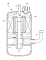
従来、円柱状のロータ100の周囲に環状のステータ102を備えた回転電機104が種々開発されている。図12のように回転電機104が圧縮機106に適用された場合、円筒状のパイプ108の中にステータ102が配置され、その中にロータ100が配置される。圧縮機106には、冷媒を供給する管110、冷媒を吐出する管112、巻線に接続される端子114、および圧縮機構116が設けられる。ロータ100が回転すると圧縮機構116に冷媒が吸入、圧縮され、吐出される。
Conventionally, various rotating
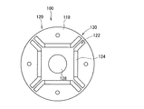
ロータ100は、図13に示す円盤形状のコアシート118を積層したロータコア120、ロータコア120に形成された磁石孔122の中に埋設された磁石124、ロータコア120の端部に配置された端板126、およびロータコア120の中心に取り付けられた回転軸128を備える。磁石孔122はロータコア120の外周までは達していず、磁石孔122の端部からロータコア120の外周まではブリッジ部130となっている。下記の特許文献1では、パルスレーザーを使用して、磁石124をロータコア120に溶接している。
The
しかし、特許文献1は、レーザー溶接を使用しているため、溶接時の温度は1500℃程度まで上昇する。磁石124が減磁し、回転性能を低下させるおそれがある。
However, since Patent Document 1 uses laser welding, the temperature during welding rises to about 1500 ° C. The
また、漏れ磁束がブリッジ部130で発生する。漏れ磁束はロータ100の回転に寄与しないため、漏れ磁束を無くす必要がある。下記の特許文献1は、漏れ磁束の対策について開示はない。
In addition, leakage magnetic flux is generated in the
本発明は、磁石孔へ磁石を埋設するときに磁石の減磁を抑制し、漏れ磁束を無くしたロータおよびその製造方法を提供することを目的とする。 An object of this invention is to provide the rotor which suppressed the demagnetization of the magnet when embedding a magnet in a magnet hole, and eliminated the leakage magnetic flux, and its manufacturing method.
本発明のロータは、電磁鋼板からなるコアシートを積層したロータコアと、前記ロータコアに形成された磁石孔と、前記磁石孔の端部からロータコアの外周まで空間を形成する切断部と、前記磁石孔の中に埋設され、ロータコアにロウ付けまたはハンダ付けされた磁石とを備える。 The rotor of the present invention includes a rotor core in which a core sheet made of an electromagnetic steel plate is laminated, a magnet hole formed in the rotor core, a cutting part that forms a space from an end of the magnet hole to the outer periphery of the rotor core, and the magnet hole And a magnet brazed or soldered to the rotor core.
前記磁石孔が、凹部、凸部またはその両方を備え、前記磁石が、磁石孔の凹部、凸部またはその両方に嵌め合わされる凸部、凹部またはその両方を備え、少なくとも前記磁石の凸部、凹部またはその両方がロータコアにロウ付けまたはハンダ付けされる。 The magnet hole includes a concave portion, a convex portion, or both, and the magnet includes a convex portion, a concave portion, or both, which are fitted into the concave portion, the convex portion, or both of the magnet hole, and at least the convex portion of the magnet, The recess or both are brazed or soldered to the rotor core.
前記磁石の凸部または磁石孔の凸部が、磁石とロータコアとを引っかかる部分を備える。 The convex part of the said magnet or the convex part of a magnet hole is provided with the part which hooks a magnet and a rotor core.
前記磁石の凸部同士、凹部同士または凸部と凹部が対向しない。磁石の一面と他面に凸部等が設けられており、一面と他面の凸部等が対向しないようにする。 The convex portions of the magnet, the concave portions, or the convex portions and the concave portions do not face each other. Convex portions and the like are provided on one surface and the other surface of the magnet so that the convex portions and the like on the one surface and the other surface do not face each other.
前記磁石の幅が変化し、少なくとも磁石の両端がロータコアにロウ付けまたはハンダ付けされる。 The width of the magnet changes, and at least both ends of the magnet are brazed or soldered to the rotor core.
前記磁石の一面がロータコアの外周側に配置され、一面の幅をWo、中心の幅をWc、他面の幅をWiとした場合に、Wi≧Wo>Wcである。 When one surface of the magnet is disposed on the outer peripheral side of the rotor core, the width of one surface is Wo, the width of the center is Wc, and the width of the other surface is Wi, Wi ≧ Wo> Wc.
、前記ロータコアに設けられた締結用孔と、前記締結用孔に挿入され、コアシート同士を固定する締結部材とを備え、前記締結用孔がコアシートにおける磁石孔よりも内側に設けられ、前記コアシートにおいて、磁石孔よりも外側にカシメを設ける。 A fastening hole provided in the rotor core, and a fastening member inserted into the fastening hole and fixing the core sheets to each other, wherein the fastening hole is provided inside a magnet hole in the core sheet, In the core sheet, caulking is provided outside the magnet hole.
本発明のロータの製造方法は、電磁鋼板を準備する工程と、前記電磁鋼板を打ち抜き加工し、磁石孔を備えたコアシートを形成する工程と、前記コアシートを積層し、ロータコアを形成する工程と、磁石を準備し、前記磁石孔に埋設する工程と、前記磁石をロウ付けまたはハンダ付けによって、ロータコアに固定する工程と、前記磁石孔の端部からロータコアの外周までを切断して空間を形成し、切断部を形成する工程とを備える。 The method for manufacturing a rotor of the present invention includes a step of preparing an electromagnetic steel plate, a step of punching the electromagnetic steel plate to form a core sheet having magnet holes, and a step of forming the rotor core by stacking the core sheets. And a step of preparing a magnet and embedding it in the magnet hole, a step of fixing the magnet to the rotor core by brazing or soldering, and cutting the space from the end of the magnet hole to the outer periphery of the rotor core. Forming a cut portion.
前記磁石孔が、凹部、凸部またはその両方を備え、前記磁石が、磁石孔の凹部、凸部またはその両方に嵌め合わされる凸部、凹部またはその両方を備え、少なくとも前記磁石の凸部、凹部またはその両方をロータコアにロウ付けまたはハンダ付けする。 The magnet hole includes a concave portion, a convex portion, or both, and the magnet includes a convex portion, a concave portion, or both, which are fitted into the concave portion, the convex portion, or both of the magnet hole, and at least the convex portion of the magnet, The recess or both are brazed or soldered to the rotor core.
前記磁石の幅が変化し、少なくとも磁石の両端をロータコアにロウ付けまたはハンダ付けする。 The width of the magnet changes, and at least both ends of the magnet are brazed or soldered to the rotor core.
本発明は従来のブリッジ部に代えて、磁石孔の端部からロータコアの外周まで空間になった切断部を形成することで、漏れ磁束を無くすことができる。また、ロウ付けまたはハンダ付けによって、磁石孔に磁石を固定するときの減磁を抑制し、磁石とロータコアを一体にすることができる。 In the present invention, the leakage magnetic flux can be eliminated by forming a cut portion that is a space from the end of the magnet hole to the outer periphery of the rotor core instead of the conventional bridge portion. Further, demagnetization when the magnet is fixed to the magnet hole by brazing or soldering can be suppressed, and the magnet and the rotor core can be integrated.
本発明のロータについて図面を用いて説明する。ロータは回転電機に用いられるものである。回転電機は、従来と同様に、圧縮機などに適用できる。複数の実施例の説明において、一の実施例で説明した内容と同一内容について他の実施例では説明を省略する場合がある。 The rotor of the present invention will be described with reference to the drawings. The rotor is used for a rotating electric machine. The rotating electrical machine can be applied to a compressor or the like, as in the past. In the description of a plurality of embodiments, the same content as that described in one embodiment may be omitted in other embodiments.
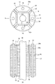
図1に示す本発明のロータ10aは、ロータコア12、締結部材14、磁石16、端板18および回転軸20を備える。ロータコア12は、磁石孔22、切断部24および締結用孔26aを有し、締結用孔26aに締結部材14が挿入され、磁石孔22の中に磁石16が埋設される。
The
ロータコア12はコアシート28を積層したものである。コアシート28は軟磁性体の電磁鋼板を打ち抜き加工して形成することができる。コアシート28の厚みは、たとえば約0.2〜1mmであり、好ましくは約0.3〜0.5mmである。コアシート28の表面は絶縁膜を被覆し、コアシート28間の渦電流を防止する。コアシート28の外形は、後述する切断部24を除いて円形になっている。
The
コアシート28は、磁石孔22が形成されている。図1(a)のように、コアシート28の平面において、磁石孔22は帯状であり、かつコの字状やV字状になるように折れ曲がっている。磁石孔22の両端はコアシート28の外周付近に配置される。各コアシート28の磁石孔22は同一形状であり、回転軸20を中心に対称になっている。ロータコア12を形成したとき、一端から他端まで磁石孔22が通じる。
The
磁石孔22の端部からコアシート28の外周まで切断部24になっている。切断部24は空間であり、電磁鋼板のない部分である。切断部24は磁石孔22をコアシート28の外周まで延長した形状である。図1の切断部24の幅は磁石孔22と同じであるが、切断部24の幅が磁石孔22と異なっていても良い。従来の図13で示すブリッジ部130が無くなり、漏れ磁束をゼロにできる。ロータコア12において、磁石孔22と切断部24よりも外側を外側ロータコア12o、内側を内側ロータコア12iとする。外側ロータコア12oと内側ロータコア12iは、磁石16を介してつながる。
A
本実施例では、外側ロータコア12oに締結用孔26aを設ける。コアシート28を積層したときに、締結用孔26aに締結部材14を挿入して、積層されたコアシート28を固定する。締結部材14として、リベット、ボルトとナットなどが挙げられ、それらの軸が締結用孔26aに入る。
In this embodiment, a
磁石16は、フェライト磁石、ネオジウム磁石、サマリウムコバルト磁石、アルニコ磁石などの焼結磁石が挙げられる。磁石16の形状は板状であり、磁石孔22の内壁にロウ付けによって固定される。磁石16の数は偶数であり、ロータコア12の外周に交互にN極とS極が交互に配置される。
Examples of the
磁石孔22の内壁に磁石16がロウ付けによって固定される。ロウ材30を溶かし、磁石孔22の内壁と磁石16との隙間に溶けたロウ材30を流し込み、ロウ付けする。磁石16における磁石孔22の内壁に対向する面を一面mと他面nとする。図1では、磁石の一面mと他面nのほぼ全体をロウ付けし、ロウ材30の薄膜層を形成しているが、複数箇所にロウ付けしても良い。ロウ付けによって、磁石16を介して外側ロータコア12oと内側ロータコア12iが固定される。
The
ロウ付けの材料は、銀ロウ、銅ロウ、黄銅ロウ、リン銅ロウ、アルミニウムロウなどが挙げられるが、融点の低い材料を使用することが好ましい。ロウ付けの材料の選択により、融点450℃以下の軟ロウ付け(ハンダ付け)であっても良い。ロウ付けを比較的低温でおこない、磁石16を減磁させにくくする。たとえばフェライト磁石のキュリー温度は約450℃、ネオジウム磁石のキュリー温度は約300℃、サマリウムコバルト磁石のキュリー温度は約750℃およびアルニコ磁石のキュリー温度は約860℃であり、ロウ付け時にキュリー温度を超えないようにすることにより、減磁を抑制できる。なお、磁石材料の選択によってキュリー温度は多少変化する。
Examples of the brazing material include silver brazing, copper brazing, brass brazing, phosphorous copper brazing, and aluminum brazing, and it is preferable to use a material having a low melting point. Soft brazing (soldering) with a melting point of 450 ° C. or less may be used depending on the choice of brazing material. Brazing is performed at a relatively low temperature to make the
端板18は非磁性体で構成され、ロータコア12の両端に配置される。非磁性体によって渦電流損を防止する。コアシート28と同様に締結用孔26bを設け、締結部材14が通されるようにする。締結部材14の軸がコアシート28の締結用孔26aと同時に締結用孔26bに通されて、ロータコア12と端板18とが一体になるように締結部材14で固定される。さらに、端板18に回転軸用孔32bを設けて、回転軸20が通過する。端板18は、磁石16が外れたときの飛び出し防止や、外側ロータコア12o同士を固定するため、回転軸用孔32bに回転軸20が接しなくても良い。
The
ロータコア12の中心の回転軸用孔32aに回転軸20が嵌め込まれて、固定される。ロータ10aを備えた回転電機が圧縮機に適用される場合、回転軸20は圧縮機構まで延び、圧縮機の回転軸にもなる。ロータコア12の側方を囲むようにしてステータが配置され、回転電機になる。ステータはコイルを備え、コイルに電流を流して発生させた磁界によって、ロータ10aを回転させる。
The
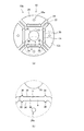
次に、ロータ10aの製造方法について説明する。(1)電磁鋼板を準備し、所定形状に打ち抜き加工をおこない、コアシート28を形成する。打ち抜き加工をおこなう際、図2(a)に示すように、コアシート28には磁石孔22、締結用孔26aおよび回転軸用孔32aを形成する。コアシート28の外形を形成したとき、同一工程または別工程で磁石孔22などを形成する。この時点で切断部24は形成されていず、磁石孔22の端部からコアシート28の外周まではブリッジ部34になっている。
Next, a method for manufacturing the
(2)コアシート28を積層してロータコア12を形成する。コアシート28を積層するとき、磁石孔22と締結用孔26aの位置が一致するようにして、ロータコア12を貫く磁石孔22と締結用孔26aが形成されるようにする。また、このとき、回転軸用孔32aもロータコア12を貫くように形成される。
(2) The
(3)ロータコア12の回転軸用孔32aに回転軸20を挿入し、固定する。固定方法は、焼嵌め、冷やし嵌め、圧入および溶接などが挙げられる。その際、コアシート28の締結用孔26aに締結部材14を挿入し、コアシート28同士を固定させておき、固定後に締結部材14を一旦取り外しても良い。
(3) The
(4)図2(b)のように、磁石孔22に磁石16を埋設し、固定する。磁石16はロウ付けによって、磁石孔22の内壁に固定する。磁石16を磁石孔22に挿入し、ロウ材30を溶かし、磁石孔22の内壁と磁石16との隙間に溶けたロウ材30を流し込むことによって、ロウ付けする。磁石16を挿入する際、ロータコア12のいずれか一方の端部に端板18を配置しても良い。磁石16を磁石孔22に挿入する段階で、磁石16が磁石孔22から抜け落ちないようにする。
(4) As shown in FIG. 2B, the
(5)ブリッジ部34を切断し、空間である切断部24を形成する。ブリッジ部34を切断する際、締結部材14でコアシート28を固定しておくことが好ましい。コアシート28と共にロータコア12の両端に端板18も固定しても良い。磁石16を磁石孔22の内壁にロウ付けしたため、ブリッジ部34を切断した後も、外側ロータコア12oと磁石16、および内側ロータコア12iと磁石16が固定される。
(5) The
ロータコア12の外周から磁石孔22の端部に向けて切断する。磁石孔22の端部から磁石12まで空間を設けておけば、切断時に切断装置が磁石16に到達せず、磁石16を保護できる。切断をおこなえるのであれば、のこぎりやカッターなど任意の切断装置を用いることができる。
Cutting from the outer periphery of the
磁石16を埋設した後にブリッジ部34を切断するため、内側ロータコア12iに対する外側ロータコア12oの位置合わせをおこなう必要がない。位置合わせをおこなわなくても、所望の位置に各ロータコア12i、12oが配置される。
Since the
なお、ロータ10aは、環状のスタータの内側に配置され、回転電機が構成される。ステータ内のコイルに電流を流し、その電流で発生した磁界によって、ロータ10aが回転する。回転電機を圧縮機に適用される場合、従来技術で示したように、回転軸20が圧縮機に接続される。ロータ10aが回転することで、圧縮機が駆動する。
In addition, the
上記のように磁石16を埋設した後にブリッジ部34を切断するため、内側ロータコア12iと外側ロータコア12oの相対的な位置合わせが必要無く、ロータコア12の外周は真円になっており、ロータコア12とステータとのエアギャップを均一にすることができる。エアギャップが均一になるため、ロータ10aが回転し易い。
Since the
磁石16の一面mと他面nは平面に限定されない。図3のロータ10bように、一面mと他面nに三角形の凸部36を設ける。磁石孔22は、その凸部36に嵌め合わされる三角形の凹部を設ける。少なくとも凸部36をロウ付けし、凸部36によって、磁石16とロータコア12とのロウ付け面積が拡大する。ロウ付け面積の拡大により、磁石16とロータコア12とのロウ付けを強固にすることができる。
The one surface m and the other surface n of the
凸部36の形状は三角形に限定されず、図4(a)〜(d)のように、半円形や四角形の凸部36であっても良い。三角形の凸部36であっても、直角三角形など、任意の三角形であっても良い。1つの磁石16に、種々の形状の凸部36を組み合わせて設けても良い。凸部36の大きさは限定されず、図4(e)、(f)のように、一面mと他面nの約7割の面積の凸部36を設けても良い。
The shape of the
凸部36の数は限定されず、図5(a)のように、1つの面に3つの凸部36など、複数の凸部36を設けても良い。凸部36の数が増えることにより、磁石16とロータコア12とのロウ付け面積を拡大することができ、固定を強固にすることができる。各面m、nの凸部36の数は異なるようにしても良い。
The number of the
図5(b)のように、磁石16に凹部38を設けても良い。磁石孔22に凸部が設けられ、磁石孔22の凸部が磁石16の凹部38に嵌め合わされる。少なくとも磁石16の凹部38をロウ付けする。また、図5(c)のように、磁石16に凸部36と凹部38を設けても良い。磁石孔22にも凹部と凸部を設け、それぞれの凸部と凹部が嵌め合わされるようにする。
As shown in FIG. 5B, the
上記の実施例では、磁石16は、一面mと他面nが対向しており、一面mの凸部36と他面nの凸部36が対向する位置に配置されている。さらに図5(d)のように、一面mの凸部36と他面nの凸部36が対向しない位置に配置されても良い。凸部36の位置が対向しないため、磁石16を焼結製造するときに磁気の異方性が乱れにくい。
In the above-described embodiment, the
磁石16に凹部38を設けた場合、図5(d)と同様に凹部38同士を対向させないようにしても良い(図5(e))。また、磁石に凹部38と凸部36の両方を設けた場合、凹部38と凸部36が対向しないようにする。すなわち、接着面積を増やすために凸部36と凹部38を設ける場合、それらが対向しないようにし、磁気の異方性を乱れにくくする。
When the
磁石16の凸部36と磁石孔22の凹部を利用して、内側ロータコア12iと外側ロータコア12oの固定を強固にしても良い。図6の凸部40は、付け根42と他の部分44において、他の部分44が付け根42の幅よりも広い部分を有するようになっている。磁石16の凸部40がロータコア12の凹部に嵌め合わさることにより、凸部40の他の部分44が凹部に引っかかる部分となっている。ロータコア12に凸部40が引っ掛かることで、回転軸20にたいする直角方向に、ロータコア12と磁石16が固定される。
The
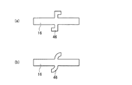
また、図7の磁石16ように、凸部46が曲がることにより凸部46に引っかかる部分を設けても良い。ロータ10aの回転軸20の軸方向以外に、凸部46が凹部から外れないようになる。ロータ10aの回転時の遠心力によって、内側ロータコア12i、磁石16および外側ロータコア12oがバラバラになるおそれがあるが、凸部46の引っ掛かり機能によって、内側ロータコア12i、磁石16および外側ロータコア12oが一体になったままになる。
Moreover, you may provide the part hooked on the
磁石16の凸部40と同じ機能を有する凸部を磁石孔22に設け、その凸部が嵌め合わされる凹部を磁石16に設けても良い。また、磁石16の凸部46と同じ機能を有する凸部を磁石孔22に設け、その凸部が嵌め合わされる凹部を磁石16に設けても良い。
A convex portion having the same function as the
図8のように、磁石16は、ロータコア12を平面視した場合に、その両端において、一面mと他面nが突出部48になっており、一面mと他面nの間が凹部50になっていても良い。一面mと他面nにおいて、突出部48が他の部分と面一になっている。板状の磁石16の両端に突出部48を設けた形状になっており、磁石16の両端が、磁石16の中心に向かって凹んだ形状になっている。方形の板体とは異なり、突出部48によってロウ付けする面積が拡大し、ロウ付けの強度が増す。
As shown in FIG. 8, when the
また、磁石16の一面mから他面nの間において磁石16の幅が変化し、一面mと他面nの両端に突出部48が形成されておれば、突出部48の形状は限定されず、図8に示すように、円弧、四角形、三角形などの突出部48が挙げられる。また、1つの磁石に異なる形状の突出部48を組み合わせても良い。
Moreover, if the width | variety of the
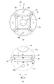
図9に示すロータ10cのように、磁石16の一面mの幅をWo、他面nの幅をWiとする。また、磁石16の厚み方向の中心の幅をWcとする。この場合、Wi≧Wo>Wcとなるようにする。これは、ロータ10cの径方向において、磁石16の一面側が大きくなると、遠心力が大きくなり、磁石16とロータコア12とのロウ付けが外れるおそれがあるためである。本実施例の構成であれば、一面mが他面nより大きくならず、遠心力が大きくなることはない。
Like the
図10のロータ10dのように、締結用孔26aを内側ロータコア12iに設けた場合、外側ロータコア12oが締結部材14で一体にならないため、外側ロータコア12oにカシメ52を設ける。カシメ52によって、コアシート28同士の固定し、コアシート28が遠心力で飛びにくくする。なお、外側ロータコア12oに締結用孔26aを設けた場合、外側ロータコア12oのカシメ52は必須ではない。締結部材14によって外側ロータコア12oのコアシート28が一体になるからである。
When the
磁石孔22の形状はコの字状やV字状に限定されない。図11のロータ10eのように、円弧状の磁石孔22および磁石16であっても良い。上記実施例と同様に、切断部24を有し、ロウ付けによって磁石16をロータコア12に固定する。
The shape of the
その他、本発明は、その主旨を逸脱しない範囲で当業者の知識に基づき種々の改良、修正、変更を加えた態様で実施できるものである。各実施例は独立的または排他的な実施例ではなく、種々の実施例の全部または一部を適宜組み合わせて実施しても良い。 In addition, the present invention can be carried out in a mode in which various improvements, modifications, and changes are added based on the knowledge of those skilled in the art without departing from the gist thereof. Each embodiment is not an independent or exclusive embodiment, and may be implemented by appropriately combining all or a part of various embodiments.
10a、10b、10c、10d、10e:ロータ
12:ロータコア
12i:内側ロータコア
12o:外側ロータコア
14:締結部材
16:磁石
18:端板
20:回転軸
22:磁石孔
24:切断部
26a、26b:締結用孔
28:コアシート
30:ロウ材
32a、32b:回転軸用孔
34:ブリッジ部
36、40、46:凸部
38:凹部
42:凸部の付け根
44:凸部の他の部分
48:突出部
50:凹部
52:カシメ
10a, 10b, 10c, 10d, 10e: Rotor 12:
Claims (11)
前記ロータコアに設けられた締結用孔と、
前記締結用孔に挿入され、コアシート同士を固定する締結部材と、
前記ロータコアに形成された磁石孔と、
前記磁石孔の端部からロータコアの外周まで形成された切断部と、
前記磁石孔の中に埋設され、ロータコアにロウ付けまたはハンダ付けされた磁石と、
を備えたロータ。 A rotor core in which core sheets made of electromagnetic steel sheets are laminated;
A fastening hole provided in the rotor core;
A fastening member that is inserted into the fastening hole and fixes the core sheets together;
Magnet holes formed in the rotor core;
A cutting part formed from the end of the magnet hole to the outer periphery of the rotor core;
A magnet embedded in the magnet hole and brazed or soldered to the rotor core;
With a rotor.
前記磁石が、磁石孔の凹部、凸部またはその両方に嵌め合わされる凸部、凹部またはその両方を備え、
少なくとも前記磁石の凸部、凹部またはその両方がロータコアにロウ付けまたはハンダ付けされた
請求項1のロータ。 The magnet hole includes a concave portion, a convex portion, or both;
The magnet includes a convex portion, a concave portion or both, which are fitted into the concave portion, the convex portion or both of the magnet hole,
The rotor according to claim 1, wherein at least convex portions, concave portions, or both of the magnets are brazed or soldered to the rotor core.
前記コアシートにおいて、磁石孔よりも外側にカシメを設けた
請求項1から6のいずれかのロータ。 The fastening hole is provided inside the magnet hole in the core sheet,
The rotor according to any one of claims 1 to 6, wherein a caulking is provided outside the magnet hole in the core sheet.
前記電磁鋼板を打ち抜き加工し、磁石孔および締結用孔を備えたコアシートを形成する工程と、
前記コアシートを積層し、ロータコアを形成する工程と、
前記締結用孔に締結部材を挿入し、コアシート同士を固定する工程と、
磁石を準備し、前記磁石孔に埋設する工程と、
前記磁石をロウ付けまたはハンダ付けによって、ロータコアに固定する工程と、
前記磁石孔の端部からロータコアの外周までを切断し、切断部を形成する工程と、
を備えたロータの製造方法。 Preparing a magnetic steel sheet;
Punching the electromagnetic steel sheet, forming a core sheet having a magnet hole and a fastening hole; and
Laminating the core sheets to form a rotor core;
Inserting a fastening member into the fastening hole and fixing the core sheets together;
Preparing a magnet and embedding it in the magnet hole;
Fixing the magnet to the rotor core by brazing or soldering;
Cutting from the end of the magnet hole to the outer periphery of the rotor core, and forming a cut portion;
A method for manufacturing a rotor comprising:
前記磁石が、磁石孔の凹部、凸部またはその両方に嵌め合わされる凸部、凹部またはその両方を備え、
少なくとも前記磁石の凸部、凹部またはその両方をロータコアにロウ付けまたはハンダ付けする
請求項9のロータの製造方法。 The magnet hole has a concave portion, a convex portion or both,
The magnet includes a convex portion, a concave portion or both, which are fitted into the concave portion, the convex portion or both of the magnet hole,
The method for manufacturing a rotor according to claim 9, wherein at least the convex portion, the concave portion or both of the magnet are brazed or soldered to the rotor core.
Priority Applications (1)
| Application Number | Priority Date | Filing Date | Title |
|---|---|---|---|
| JP2014070909A JP2015192594A (en) | 2014-03-31 | 2014-03-31 | Rotor and manufacturing method thereof |
Applications Claiming Priority (1)
| Application Number | Priority Date | Filing Date | Title |
|---|---|---|---|
| JP2014070909A JP2015192594A (en) | 2014-03-31 | 2014-03-31 | Rotor and manufacturing method thereof |
Publications (1)
| Publication Number | Publication Date |
|---|---|
| JP2015192594A true JP2015192594A (en) | 2015-11-02 |
Family
ID=54426698
Family Applications (1)
| Application Number | Title | Priority Date | Filing Date |
|---|---|---|---|
| JP2014070909A Pending JP2015192594A (en) | 2014-03-31 | 2014-03-31 | Rotor and manufacturing method thereof |
Country Status (1)
| Country | Link |
|---|---|
| JP (1) | JP2015192594A (en) |
Cited By (5)
| Publication number | Priority date | Publication date | Assignee | Title |
|---|---|---|---|---|
| CN110224513A (en) * | 2019-05-28 | 2019-09-10 | 佛山市顺德区金泰德胜电机有限公司 | A kind of mounting structure of rotor core and magnet steel |
| WO2019189217A1 (en) * | 2018-03-29 | 2019-10-03 | 日本電産株式会社 | Rotor core, rotor, and motor |
| KR20200108636A (en) * | 2019-03-11 | 2020-09-21 | 한국전자기술연구원 | Rotor using bonded magnet and motor comprising the same |
| FR3144721A1 (en) * | 2022-12-29 | 2024-07-05 | Commissariat à l'Energie Atomique et aux Energies Alternatives | Reversible mounting of permanent magnet in an electrical machine |
| FR3147912A1 (en) * | 2023-04-14 | 2024-10-18 | Commissariat à l'Energie Atomique et aux Energies Alternatives | Electric machine for easy extraction of permanent magnet and tools used for extraction |
-
2014
- 2014-03-31 JP JP2014070909A patent/JP2015192594A/en active Pending
Cited By (8)
| Publication number | Priority date | Publication date | Assignee | Title |
|---|---|---|---|---|
| WO2019189217A1 (en) * | 2018-03-29 | 2019-10-03 | 日本電産株式会社 | Rotor core, rotor, and motor |
| CN111919358A (en) * | 2018-03-29 | 2020-11-10 | 日本电产株式会社 | Rotor core, rotor and motor |
| CN111919358B (en) * | 2018-03-29 | 2023-05-30 | 日本电产株式会社 | Rotor core, rotor and motor |
| KR20200108636A (en) * | 2019-03-11 | 2020-09-21 | 한국전자기술연구원 | Rotor using bonded magnet and motor comprising the same |
| KR102349405B1 (en) * | 2019-03-11 | 2022-01-11 | 한국전자기술연구원 | Rotor using bonded magnet and motor comprising the same |
| CN110224513A (en) * | 2019-05-28 | 2019-09-10 | 佛山市顺德区金泰德胜电机有限公司 | A kind of mounting structure of rotor core and magnet steel |
| FR3144721A1 (en) * | 2022-12-29 | 2024-07-05 | Commissariat à l'Energie Atomique et aux Energies Alternatives | Reversible mounting of permanent magnet in an electrical machine |
| FR3147912A1 (en) * | 2023-04-14 | 2024-10-18 | Commissariat à l'Energie Atomique et aux Energies Alternatives | Electric machine for easy extraction of permanent magnet and tools used for extraction |
Similar Documents
| Publication | Publication Date | Title |
|---|---|---|
| JP4598343B2 (en) | Permanent magnet motor | |
| CN108292866B (en) | Motor and method for manufacturing motor | |
| JP6273499B2 (en) | Permanent magnet embedded motor and method for manufacturing the same | |
| JP6627784B2 (en) | Rotating electric machine rotor | |
| JP4712059B2 (en) | Synchronous motor rotor and compressor | |
| WO2017126053A1 (en) | Permanent magnet synchronous motor, compressor and air conditioner | |
| CN102629791A (en) | Rotor for rotary electric machine and manufacturing method thereof | |
| JP2015192594A (en) | Rotor and manufacturing method thereof | |
| JP2015195638A (en) | Rotor | |
| CN108462268B (en) | Rotor of rotating electric machine | |
| US20120043849A1 (en) | Stator for electric rotating machine and method for manufacturing the same | |
| JP2010093906A (en) | Permanent magnet type rotating machine | |
| JP2015202027A (en) | Rotor | |
| JP5014364B2 (en) | Permanent magnet motor rotor | |
| CN107408850A (en) | Permanent magnet embedded motors, blowers, and refrigeration and air conditioners | |
| JP2010183800A (en) | Rotor of electric motor, electric motor, air blower and compressor | |
| JP2015192587A (en) | rotor | |
| JP2010130885A (en) | Rotating electric machine | |
| JP2009081939A (en) | Rotating electric machine rotor and rotating electric machine | |
| JP2015192590A (en) | Rotor | |
| JP2012125111A (en) | Rotor of outer rotor type rotary machine | |
| JP6350964B2 (en) | Rotor core, rotor using the rotor core, and method of manufacturing rotor core | |
| JP2001095183A (en) | Self-starting permanent magnet synchronous motor | |
| JP5274496B2 (en) | Magnetic metal body and method for manufacturing rotating electrical machine using magnetic metal body | |
| JP2015186353A (en) | permanent magnet motor |