JP2015199416A - webbing take-up device - Google Patents
webbing take-up device Download PDFInfo
- Publication number
- JP2015199416A JP2015199416A JP2014078894A JP2014078894A JP2015199416A JP 2015199416 A JP2015199416 A JP 2015199416A JP 2014078894 A JP2014078894 A JP 2014078894A JP 2014078894 A JP2014078894 A JP 2014078894A JP 2015199416 A JP2015199416 A JP 2015199416A
- Authority
- JP
- Japan
- Prior art keywords
- spool
- webbing
- support member
- support
- webbing take
- Prior art date
- Legal status (The legal status is an assumption and is not a legal conclusion. Google has not performed a legal analysis and makes no representation as to the accuracy of the status listed.)
- Pending
Links
- 230000037431 insertion Effects 0.000 claims description 43
- 238000003780 insertion Methods 0.000 claims description 43
- 230000000903 blocking effect Effects 0.000 claims 1
- 238000004804 winding Methods 0.000 description 10
- 230000002265 prevention Effects 0.000 description 8
- 230000001133 acceleration Effects 0.000 description 6
- 230000002093 peripheral effect Effects 0.000 description 5
- 101000666896 Homo sapiens V-type immunoglobulin domain-containing suppressor of T-cell activation Proteins 0.000 description 4
- 102100038282 V-type immunoglobulin domain-containing suppressor of T-cell activation Human genes 0.000 description 4
- 230000000694 effects Effects 0.000 description 3
- 230000004308 accommodation Effects 0.000 description 1
- 230000005540 biological transmission Effects 0.000 description 1
- 230000015572 biosynthetic process Effects 0.000 description 1
- 239000012141 concentrate Substances 0.000 description 1
- 238000010438 heat treatment Methods 0.000 description 1
- 239000007769 metal material Substances 0.000 description 1
- 230000003014 reinforcing effect Effects 0.000 description 1
- 238000004381 surface treatment Methods 0.000 description 1
Images


Landscapes
- Automotive Seat Belt Assembly (AREA)
Abstract
Description
本発明は、ウェビングがスプールの挿通孔に貫通配置されることによってウェビングの基端部がスプールに係止されるウェビング巻取装置に関する。 The present invention relates to a webbing take-up device in which a base end portion of a webbing is locked to a spool by the webbing being disposed through the insertion hole of the spool.
挿通孔がスプール軸直交方向にスプールに貫通形成され、この挿通孔にウェビングが貫通配置されたウェビング巻取装置がある(一例として下記特許文献1を参照)。この種のウェビング巻取装置では、ウェビングの基端部にループ部に形成されて、ループ部の内側には円柱状のウェビングストッパが配置される。これによって、ウェビングのループ部(基端部)は、スプールの挿通孔の一側から他側へ通過できず、ウェビングがスプールに係止される。 There is a webbing take-up device in which an insertion hole is formed through the spool in a direction perpendicular to the spool axis, and the webbing is disposed through the insertion hole (see Patent Document 1 below as an example). In this type of webbing take-up device, a loop portion is formed at the base end portion of the webbing, and a cylindrical webbing stopper is disposed inside the loop portion. Thus, the loop portion (base end portion) of the webbing cannot pass from one side of the insertion hole of the spool to the other side, and the webbing is locked to the spool.
ここで、ウェビングが先端側へ引張られると、スプールにおける挿通孔の一端近傍には、挿通孔を開くような荷重がウェビングのループ部から付与される。このため、このような荷重を考慮する必要がある。 Here, when the webbing is pulled toward the front end side, a load that opens the insertion hole is applied to the vicinity of one end of the insertion hole in the spool from the loop portion of the webbing. For this reason, it is necessary to consider such a load.
本発明は、上記事実を考慮して、スプールにおけるウェビングの基端部からの荷重耐性を向上できるウェビング巻取装置を得ることが目的である。 In view of the above fact, an object of the present invention is to obtain a webbing take-up device that can improve load resistance from a base end portion of a webbing in a spool.
請求項1に記載のウェビング巻取装置は、基端部に抜止部材が設けられたウェビングと、前記ウェビングが貫通可能な挿通孔が形成されて前記抜止部材によって前記挿通孔の一側で前記ウェビングの基端部が係止されるスプールと、前記スプールに設けられると共に前記スプールよりも機械的強度が高く設定されて、前記ウェビングが引張られた際に前記ウェビングの基端部の幅方向端部から前記ウェビングの引張荷重が付与される支持部材と、を備えている。 The webbing take-up device according to claim 1, wherein a webbing provided with a retaining member at a base end portion and an insertion hole through which the webbing can pass are formed, and the webbing is formed on one side of the insertion hole by the retaining member. A spool to which the base end portion of the webbing is locked, and a width direction end portion of the base end portion of the webbing when the webbing is pulled by being provided on the spool and having a mechanical strength higher than that of the spool. And a support member to which a tensile load of the webbing is applied.
請求項1に記載のウェビング巻取装置では、ウェビングが引張られるとスプールに設けられた支持部材にウェビングの基端部からウェビングの引張荷重が付与される。ここで、支持部材の機械的強度はスプールよりも高く設定される。このため、スプールにおけるウェビングの基端部からの荷重耐性を向上できる。 In the webbing take-up device according to the first aspect, when the webbing is pulled, a tensile load of the webbing is applied to the support member provided on the spool from the base end portion of the webbing. Here, the mechanical strength of the support member is set higher than that of the spool. For this reason, the load tolerance from the base end part of the webbing in a spool can be improved.
請求項2に記載のウェビング巻取装置は、請求項1に記載のウェビング巻取装置において、前記支持部材は、前記ウェビングが貫通される挿通部を有すると共に前記挿通部の内幅が部分的に拡大されることによって形成されて前記ウェビングの基端部が当接される一対の支持面を有している。 The webbing take-up device according to claim 2 is the webbing take-up device according to claim 1, wherein the support member has an insertion portion through which the webbing penetrates and an inner width of the insertion portion is partially It has a pair of support surfaces which are formed by enlarging and contact the base end portion of the webbing.
請求項2に記載のウェビング巻取装置では、支持部材の挿通部の内幅が部分的に拡大されることによって形成された一対の支持面にウェビングの基端部が当接され、ウェビングの基端部からの荷重をこれらの支持面によって受けることができる。 In the webbing take-up device according to claim 2, the base end portion of the webbing is brought into contact with a pair of support surfaces formed by partially expanding the inner width of the insertion portion of the support member. Loads from the ends can be received by these support surfaces.
請求項3に記載のウェビング巻取装置は、請求項2に記載のウェビング巻取装置において、前記挿通部は、スプール軸方向中央側へ向けて開口された挿通溝とされ、前記支持部材は、前記挿通溝よりもスプール軸方向外側でスプール周方向に連続している。 The webbing take-up device according to a third aspect is the webbing take-up device according to the second aspect, wherein the insertion portion is an insertion groove opened toward the center side in the spool axial direction, and the support member is It is continuous in the spool circumferential direction outside the insertion groove in the spool axial direction.
請求項3に記載のウェビング巻取装置では、ウェビングの基端部からの荷重が一対の支持面に作用した際に、一対の支持面が互いに離れるような支持部材の変形を効果的に抑制できる。 In the webbing take-up device according to claim 3, when a load from the base end portion of the webbing acts on the pair of support surfaces, it is possible to effectively suppress deformation of the support member such that the pair of support surfaces separate from each other. .
請求項4に記載のウェビング巻取装置は、請求項2又は請求項3に記載のウェビング巻取装置において、前記支持部材の前記支持面部分の強度が前記支持部材の他の部位よりも高く設定されている。 The webbing take-up device according to claim 4 is the webbing take-up device according to claim 2 or 3, wherein the strength of the support surface portion of the support member is set higher than other portions of the support member. Has been.
請求項4に記載のウェビング巻取装置では、ウェビングの基端部からの荷重が支持面に作用した際に、支持部材における支持面部分の変形を効果的に抑制できる。 In the webbing take-up device according to the fourth aspect, when the load from the base end portion of the webbing acts on the support surface, the deformation of the support surface portion in the support member can be effectively suppressed.
請求項5に記載のウェビング巻取装置は、請求項4に記載のウェビング巻取装置において、前記支持部材から径方向外側へ凸部が突出形成され、前記支持面部分が前記凸部に設定されている。 The webbing take-up device according to a fifth aspect is the webbing take-up device according to the fourth aspect, wherein a convex portion is formed to protrude radially outward from the support member, and the support surface portion is set to the convex portion. ing.
請求項5に記載のウェビング巻取装置によれば、支持部材の支持面部分の強度を凸部とは別の部位に支持面部分が設定された場合に比べて高くできる。 According to the webbing take-up device of the fifth aspect, the strength of the support surface portion of the support member can be increased as compared with the case where the support surface portion is set at a site different from the convex portion.
請求項6に記載のウェビング巻取装置は、請求項1から請求項5の何れか1項に記載のウェビング巻取装置において、前記支持部材は、前記スプールの軸方向一端部に装着されている。 The webbing take-up device according to claim 6 is the webbing take-up device according to any one of claims 1 to 5, wherein the support member is attached to one end of the spool in the axial direction. .
請求項6に記載のウェビング巻取装置では、支持部材がスプールの軸方向一端部に装着されるため、支持部材をスプール軸方向に向けてスプールに組付けることができる。 In the webbing take-up device according to the sixth aspect, since the support member is attached to one end of the spool in the axial direction, the support member can be assembled to the spool in the spool axial direction.
請求項7に記載のウェビング巻取装置は、請求項1から請求項6の何れか1項に記載のウェビング巻取装置において、前記スプールと一体に回転可能に設けられ、車両緊急時に引出方向への回転が制限されるロックベースと、前記車両緊急時に前記スプールが前記ロックベースに対して引出方向に回転されることによって変形されて前記スプールの回転力を吸収するエネルギー吸収部材と、前記スプールに対して相対回転不能に設けられた前記支持部材に所定回数だけ相対回転可能に係合されて、前記スプールの前記ロックベースに対する引出方向への回転が前記所定回数になると前記スプールの引出方向への回転を阻止する回転阻止部材と、を備えている。 A webbing take-up device according to a seventh aspect of the present invention is the webbing take-up device according to any one of the first to sixth aspects, wherein the webbing take-up device is provided so as to be rotatable integrally with the spool and moves in a pull-out direction in the event of a vehicle emergency. A lock base that is limited in rotation, an energy absorbing member that is deformed by rotating the spool in the pull-out direction with respect to the lock base in an emergency of the vehicle, and absorbs the rotational force of the spool, and the spool On the other hand, when the spool is engaged with the support member provided so as not to rotate relative to the lock base a predetermined number of times and the spool rotates in the pull-out direction with respect to the lock base, the spool moves in the pull-out direction. A rotation preventing member that prevents rotation.
請求項7に記載のウェビング巻取装置によれば、支持部材の機械的強度がスプールよりも高いため、スプールの引出方向の回転阻止状態で、支持部材が回転阻止部材から受ける回転力に対して高い強度を確保できる。 According to the webbing take-up device of the seventh aspect, since the mechanical strength of the support member is higher than that of the spool, the rotation force received by the support member from the rotation prevention member in the rotation prevention state of the spool in the pulling-out direction. High strength can be secured.
請求項8に記載のウェビング巻取装置は、請求項7に記載のウェビング巻取装置において、前記支持部材と前記スプールとの間で回転力の伝達が可能とされて前記支持部材の前記スプールに対する相対回転を阻止する回止め部が複数設けられている。 The webbing take-up device according to claim 8 is the webbing take-up device according to claim 7, wherein a rotational force can be transmitted between the support member and the spool, and the support member with respect to the spool. A plurality of stop portions for preventing relative rotation are provided.
請求項8に記載のウェビング巻取装置では、支持部材とスプールとの間で回転力が伝達される際に、この回転力が複数の回止め部に分散される。これによって、支持部材とスプールとの間で回転力が伝達される際の応力集中を抑制できる。 In the webbing take-up device according to the eighth aspect, when the rotational force is transmitted between the support member and the spool, the rotational force is distributed to the plurality of rotation stop portions. Thereby, the stress concentration when the rotational force is transmitted between the support member and the spool can be suppressed.
以上説明したように、本発明に係るウェビング巻取装置では、スプールにおけるウェビングの基端部からの荷重耐性を向上できる。 As described above, in the webbing take-up device according to the present invention, it is possible to improve load resistance from the base end portion of the webbing in the spool.
次に、本発明の各実施の形態を図1から図5に基づいて説明する。なお、各図において矢印FRはウェビング巻取装置10、110の前側を示し、矢印LHは左側を示し、矢印UPは上側を示す。
Next, each embodiment of the present invention will be described with reference to FIGS. In each figure, the arrow FR indicates the front side of the
<第1の実施の形態の構成>
図1に示されるように、本実施の形態に係るウェビング巻取装置10は、リヤシートの後側で車両の骨格部材や補強部材に固定されるフレーム12を備えている。フレーム12は左右方向に対向する壁部14、16を備えており、壁部14と壁部16との間にはスプール18が設けられている。スプール18の軸方向は左右方向に沿っており、スプール18には中心軸線に沿って貫通孔20が形成されている。
<Configuration of First Embodiment>
As shown in FIG. 1, the
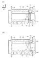
また、図2及び図3(A)に示されるように、スプール18には挿通孔22が形成されている。図3(A)に示されるように、挿通孔22は、スプール18の中心軸線から径方向にずれた位置でスプール18軸直交方向(図3(A)の矢印A方向)に平行な方向にスプール18を貫通していると共に中間部で貫通孔20に繋がっている。挿通孔22の一側からはウェビング24が挿通されている。ウェビング24の基端部には環状のループ部26が形成されており、ループ部26の内側には、抜止部材としての円柱形状のウェビングストッパ28が配置されている。
As shown in FIGS. 2 and 3A, an
図3(A)に示されるように、ウェビングストッパ28が設けられた状態でのループ部26の外形は、スプール18軸方向に見た挿通孔22の内幅よりも大きく、これによって、ループ部26は挿通孔22を通過できない。ループ部26が位置する挿通孔22の一端部はスプール18軸方向に見て拡幅された収容部30とされており、収容部30内にループ部26が配置される。
As shown in FIG. 3A, the outer shape of the
このようにして、ウェビング24の基端部がスプール18に係止されており、スプール18が軸周りに巻取方向に回転されることによって、ウェビング24がスプール18の外周部に層状に巻取られる。また、図1及び図2に示されるように、スプール18の軸方向両端部にはフランジ部32が形成されており、これらのフランジ部32では、スプール18径方向寸法がスプール18の軸方向中央側よりも大きい。さらに、図1に示されるように、スプール18の左側には回転部材34が設けられている。回転部材34は、スプール18の左側から貫通孔20に嵌合されており、これによって、回転部材34のスプール18に対する相対回転が阻止されている。
In this way, the base end of the
フレーム12の左側には、車両衝突時等の車両緊急時に作動するプリテンショナ36が設けられている。プリテンショナ36が作動されることによって、回転部材34が巻取方向に回転される。これによって、スプール18が巻取方向に回転されて、ウェビング24がスプール18に巻取られる。また、プリテンショナ36の左側にはスプリングハウジング38が設けられており、回転部材34がスプリングハウジング38に回転自在に支持されている。スプリングハウジング38内には、渦巻きばね(図示省略)が設けられている。渦巻きばねは、回転部材34に係合されており、これによって、スプール18が巻取方向へ付勢されている。
On the left side of the
一方、スプール18の貫通孔20の内側には、エネルギー吸収部材としてのトーションシャフト40が設けられている。トーションシャフト40は軸部42を備えており、軸部42の左側には連結部44が形成されている。また、軸部42の右側には連結部46が形成されており、更に、連結部46の右側には支持軸48がスプール18に対して同軸上に突出形成されている。トーションシャフト40の左側の連結部44は、スプール18の貫通孔20の内側でスプール18に係合しており、これによって、トーションシャフト40のスプール18に対する相対回転が阻止されている。
On the other hand, a
また、スプール18の右側にはロックベース50が設けられている。ロックベース50の左側の端面は、スプール18の右側の端面に当接されており、また、ロックベース50は、トーションシャフト40の右側の連結部46に係合されてトーションシャフト40に対する相対回転が阻止されている。これによって、ロックベース50がスプール18と一体的に回転可能とされている。但し、ロックベース50の回転が阻止された状態で、トーションシャフト40の機械的強度を上回る回転力がスプール18に作用すると、トーションシャフト40の軸部42が捻り変形されながらスプール18が回転される。
A
さらに、ロックベース50にはロックパウル52が回動可能に支持されている。ロックパウル52は、フレーム12の右側の壁部16に形成されたラチェット孔54の内側に配意されており、回動されることによってラチェット孔54のラチェット歯に噛合う。これによって、ロックベース50の巻取方向とは反対の引出方向への回転が阻止される。ロックベース50の右側にはセンサ機構56が設けられている。センサ機構56はVギヤ58を備えている。Vギヤ58は外周部にラチェット歯が形成されており、トーションシャフト40の支持軸48に回転自在に支持されている。また、Vギヤ58にはロックパウル52に形成された係合軸60が係合されており、ロックベース50がVギヤ58に対して引出方向に相対回転されることによってロックパウル52が回動されてラチェット孔54のラチェット歯に噛合う。
Further, a
また、ロックベース50とVギヤ58との間には、図示しないスプリングが設けられており、ロックベース50と共にスプリングが引出方向へ回転されると、Vギヤ58がスプリングによって引出方向に押圧される。これによって、Vギヤ58はロックベース50に追従して引出方向へ回転される。但し、ロックベース50が引出方向に回転した際にスプリングが弾性変形されることによって、ロックベース50はVギヤ58に対して引出方向に相対回転できる。
A spring (not shown) is provided between the
一方、センサ機構56は第1カバー62を備えており、Vギヤ58は第1カバー62内に収容されている。第1カバー62の内側には、内歯のラチェット歯がトーションシャフト40の支持軸48に対して同軸上に形成されている。このラチェット歯に対応してVギヤ58にはWSIR機構を構成するWパウル64が揺動可能に支持されている。WSIR機構は、車両衝突時等の車両緊急時にスプール18が所定の大きさ以上の回転加速度で引出方向に回転されることによって作動される。スプール18と共にVギヤ58が所定の大きさ以上の回転加速度で引出方向に回転されると、Wパウル64が揺動されて第1カバー62のラチェット歯に係合される。これによって、Vギヤ58の引出方向への回転が阻止される。
On the other hand, the
第1カバー62の右側には第2カバー66が設けられており、第1カバー62は第2カバー66の内側に収容されている。トーションシャフト40の支持軸48の先端側は、第1カバー62を貫通して、第2カバー66に回転自在に支持されている。第2カバー66にはVSIR機構を構成する加速度センサ68が設けられており、VSIR機構は車両衝突時等の車両急減速状態で作動される。加速度センサ68は、車両衝突時に慣性で転動する硬球70を備えている。硬球70が転動すると、加速度センサ68のセンサパウル72が硬球70によって押上げられてVギヤ58のラチェット歯に噛合う。これによって、Vギヤ58の引出方向への回転が阻止される。
A
図1及び図2に示されるように、スプール18に形成された貫通孔20の一端部(右側端部)は拡径されて嵌合部74とされており、嵌合部74はウェビング24が挿通される挿通孔22の一端部に繋がっている。嵌合部74には支持部材76が嵌合されている。支持部材76は全体的にスプール18よりも機械的強度、特に、圧縮強度及びせん断強度の少なくとも一方が高い金属材料によって形成されている。また、支持部材76はリング状に形成されており、支持部材76の内周形状はスプール18に対して同軸上の円形とされている。図1及び図2に示されるように、支持部材76のスプール18軸方向他端(左側端部)には底部78が形成されている。底部78の径方向中央側には円孔80が形成されており、円孔80にはトーションシャフト40が貫通される。
As shown in FIGS. 1 and 2, one end portion (right end portion) of the through
支持部材76の外周部には回止め部としての複数の凸部82が突出形成されており、凸部82では支持部材76の外径寸法が、支持部材76における凸部82とは別の部位よりも長くなる。これらの凸部82に対応して嵌合部74は回止め部としての複数の凹部84を備えており、支持部材76が嵌合部74に嵌合されると、各凸部82が各凹部84に嵌合され、これによって、支持部材76のスプール18に対する相対回転が阻止される。
A plurality of
図2に示されるように、支持部材76の底部78には、スプール18軸方向他側(左側)へ向けて開口した挿通部としての挿通溝86が形成されている。図3(B)に示されるように、挿通溝86は、支持部材76の中心軸線から径方向にずれた位置で支持部材76軸直交方向(図3(B)の矢印B方向)に平行な方向に支持部材76を貫通していると共に中間部で円孔80に繋がっている。支持部材76が嵌合部74に嵌合された状態で挿通溝86はスプール18の挿通孔22とスプール18軸方向に対向し、挿通孔22を貫通したウェビング24の幅方向一端部(右側の端部)が挿通溝86を貫通する。
As shown in FIG. 2, an
挿通溝86の一端部は、スプール18軸方向に見て拡幅された支持面部分としての支持部88とされており、ウェビングストッパ28が設けられたループ部26におけるウェビング24幅方向一端部が支持部88内に配置される。支持部88の挿通溝86を介した両側は支持面90とされ、支持部88内に配置されたループ部26が当接される。また、支持部88は、支持部材76において複数の凸部82の1つの形成位置に形成されており、支持部88は、支持部材76の軸方向に、1つの凸部82に部分的に重なっている。このため、支持部材76における支持面90の設定部位は、支持部材76における支持面90の設定部位とは別の部位に比べてスプール18径方向寸法が長い。
One end portion of the
<第1実施の形態の作用、効果>
次に、本実施の形態の作用並びに効果について説明する。
<Operation and Effect of First Embodiment>
Next, the operation and effect of the present embodiment will be described.
本ウェビング巻取装置10では、車両衝突時等の車両緊急時に、乗員の身体に装着されたウェビング24が引張られて、スプール18と共にロックベース50が所定の大きさ以上の回転加速度で引出方向へ回転されると、センサ機構56のWSIR機構が作動される。また、車両衝突による車両の急減速状態では、センサ機構56のVSIR機構が作動される。このように、WSIR機構やVSIR機構が作動されることによって、Vギヤ58の引出方向の回転が阻止される。
In the webbing take-up
この状態で、スプール18と共にロックベース50が引出方向へ回転され、これによって、ロックベース50がVギヤ58に対して引出方向へ相対回転されると、ロックベース50に設けられたロックパウル52が回動される。これによって、ロックパウル52の歯が右側の壁部16のラチェット孔54の内歯に係合されると、ロックベース50の引出方向への回転が阻止されて、スプール18の引出方向への回転が阻止される。これによって、ウェビング24のスプール18からの引出しが阻止される。
In this state, when the
また、この状態で、スプール18の引出方向への回転力がトーションシャフト40の軸部42の機械的強度を上回ると、軸部42が捻り変形されながらスプール18が引出方向へ回転される。このスプール18の回転量分だけウェビング24がスプール18から引出されると共に、スプール18の回転力のエネルギーの一部がトーションシャフト40の捻り変形に供されて吸収される。
In this state, when the rotational force in the pull-out direction of the
一方、センサ機構56が作動されてスプール18の引出方向への回転が阻止された状態や、スプール18からウェビング24が全て引出された全引出状態でウェビング24が矢印F方向(先端側)へ引張られると、図3(A)に示されるように、ウェビング24のループ部26(基端部)から挿通孔22を広げようとする荷重F1、F2が挿通孔22の収容部30に付与される。これに対して、図3(B)に示されるように、スプール18の軸方向一端部では、スプール18に設けられた支持部材76の支持部88の内側にウェビング24のループ部26が入っており、ループ部26からの荷重F1、F2を支持部88の両支持面90によって支持できる。
On the other hand, the
ここで、支持部材76の圧縮強度はスプール18の圧縮強度よりも高く設定される。したがって、ループ部26からの荷重F1、F2が支持部88の支持面90に作用した際に支持部88が圧縮変形し難く、両支持面90の間隔が広がる変形が生じ難い。このため、スプール18に支持部材76を設けることによって、ウェビング24からの荷重F1、F2に対して高い荷重耐性を得ることができる。
Here, the compressive strength of the
しかも、支持部材76の支持部88が凸部82の形成位置に形成されており、支持部88は、支持部材76の軸方向に、1つの凸部82に部分的に重なっている。支持部材76において凸部82は、支持部材76における凸部82とは別の部位に比べてスプール18径方向寸法が長く、このため、凸部82に支持面90が設定されることによって支持部88を大きくできる。これによって、ウェビング24からの荷重F1、F2に対する圧縮強度が支持部材76における凸部82の形成部位とは別の部位に比べて高い。これによって、支持部材76自体を大きくすることなくウェビング24からの荷重F1、F2に対して高い強度を確保できる。
Moreover, the
また、支持部材76の挿通溝86よりもスプール18軸方向一側(右側)では、支持部材76が環状に連続している。このため、両支持面90を互いに離間させるような荷重が支持部材76に作用しても、両支持面90よりもスプール18軸方向一側の支持部材76の環状部分によって支持部88を支持できる。しかも、両支持面90が互いに離間されるような荷重が両支持面90に作用すると、支持部材76の支持部88と支持部材76の環状部分との間にはせん断応力が作用する。ここで、支持部材76はスプール18よりもせん断荷重に対する強度が高いため、支持部材76の支持部88と支持部材76の環状部分との間で変形等が生じ難い。以上のことからも、ウェビング24からの荷重F1、F2に対して荷重耐性を得ることができる。
Further, on the one axial side (right side) of the
また、支持部材76が嵌合される嵌合部74は、スプール18の軸方向一端に形成される。このため、スプール18の軸方向に支持部材76を容易に組付けることができる。しかも、スプール18の軸方向一端にはフランジ部32が形成されるため、スプール18の軸方向中央側に比べてスプール18径方向寸法が長い。このため、スプール18に嵌合部74が形成されても、スプール18の軸方向一端部における機械的強度の低下を抑制できる。
Further, the
なお、本実施の形態では、スプール18の軸方向一端部に支持部材76を設けた構成としたが、支持部材76の構造が左右反転された支持部材をスプール18の軸方向他端部に設けてもよく、また、スプール18の軸方向両端部に支持部材76を設けてもよい。更には、支持部材は、ウェビングの基端部からの荷重を受けることができ、且つ、このような荷重に対する機械的強度がスプールよりも高ければよく、スプールにおける支持部材の装着位置は特に限定されるものではない。
In the present embodiment, the
<第2の実施の形態の構成>
本発明の第2の実施の形態を説明するにあたり、前記第1の実施の形態と基本的に同一の部位に関しては同一の符号を付与してその詳細な説明を省略する。
<Configuration of Second Embodiment>
In describing the second embodiment of the present invention, components that are basically the same as those of the first embodiment are given the same reference numerals, and detailed descriptions thereof are omitted.
図4に示されるように、本実施の形態に係るウェビング巻取装置110では、支持部材76に収容部112が形成されている。収容部112は、支持部材76の底部78よりも軸方向一側(右側)で支持部材76の内側の一部が拡径されることによって形成されている。また、収容部112は、支持部材76をその軸方向に見て支持部88とは反対側に形成されている。この収容部112の内側には回転阻止部材としてのFLストッパ114が収容されている。
As shown in FIG. 4, in the webbing take-up
FLストッパ114は、支持部材76軸周りに略C字形状に湾曲されている。FLストッパ114の周方向端面114A、114Bは、収容部112の周方向両端面112A、112Bと対向されており、これによって、FLストッパ114の支持部材76に対する相対回転が制限される。また、FLストッパ114の厚さ寸法(支持部材76軸方向寸法)は、収容部112の深さ寸法(支持部材76軸方向寸法)よりも小さく、これによって、FLストッパ114は収容部112の内側で支持部材76軸方向に移動できる。
The
本実施の形態では、ロックベース50のスプール18側の面(左側面)には筒部116が形成されている。筒部116はスプール18に対して同軸上に形成されている。筒部116の内周形状は、トーションシャフト40の右側の連結部46の外周形状よりも僅かに大きな相似形状とされている。トーションシャフト40の連結部46が筒部116の内側に嵌合されることによって、ロックベース50はトーションシャフト40に対する相対回転が阻止される。
In the present embodiment, a
筒部116の外周部には雄ねじ118が形成されており、この雄ねじ118に対応して、FLストッパ114の径方向内側面には雌ねじ120が形成されている。図5(A)に示されるように、FLストッパ114は初期状態で支持部材76の底部78側に配置されており、この状態でFLストッパ114の雌ねじ120がロックベース50の筒部116の雄ねじ118に螺合されている。FLストッパ114が筒部116周りに引出方向へ回転されると、図5(B)に示されるように、FLストッパ114の雌ねじ120が筒部116の雄ねじ118に案内されてロックベース50側へ移動される。
A
<第2の実施の形態の作用、効果>
スプール18が引出方向へ回転されると、支持部材76の凸部82における巻取方向側の面が、スプール18の嵌合部74の凹部84における巻取方向側の面によって押圧される。これによって、支持部材76がスプール18と一体的に引出方向へ回転される。また、支持部材76が引出方向へ回転されると、FLストッパ114の巻取方向側の端面114Aが収容部112の巻取方向側の端面112Aに押圧される。これによって、FLストッパ114が支持部材76と一体的に引出方向へ回転される。
<Operation and Effect of Second Embodiment>
When the
センサ機構56が作動されてロックベース50の引出方向の回転が阻止された状態で、スプール18がロックベース50に対して引出方向に相対回転されると、FLストッパ114がスプール18と共に引出方向へ回転される。これによって、FLストッパ114の雌ねじ120がロックベース50の筒部116の雄ねじ118に案内されてFLストッパ114がロックベース50側へ移動される。
When the
スプール18が引出方向へ一定回数回転されると、図5(B)に示されるように、FLストッパ114のロックベース50側の面がロックベース50のスプール18側の面に当接される。この状態では、FLストッパ114はロックベース50側へ移動することができないため、FLストッパ114の筒部116周りの引出方向の回転が阻止される。FLストッパ114の引出方向の回転が阻止されることによって、支持部材76の引出方向の回転が阻止され、更には、スプール18の引出方向の回転が阻止される。これによって、ウェビング24のスプール18からの引出しやトーションシャフト40の軸部42の捻り変形が終了される。
When the
ところで、FLストッパ114の移動が阻止された状態でスプール18に引出方向の回転力が付与されると、FLストッパ114の周方向両端側では、FLストッパ114の雌ねじ120がロックベース50の筒部116の雄ねじ118から受ける軸力によって径方向外側へ変形しようとする。ここで、本実施の形態では、このようなFLストッパ114の変形が、スプール18よりも圧縮強度が高い支持部材76によって抑制される。このため、ロックベース50の雄ねじ118とFLストッパ114の雌ねじ120との螺合状態を維持できる。
By the way, when the pulling direction rotational force is applied to the
また、このようなFLストッパ114の変形がスプール18よりも圧縮強度が高い支持部材76によって抑制されるため、FLストッパ114を収容するための構成をスプール18の一側に設けることによるスプール18の大型化を抑制できる。これによって、スプール18の径方向寸法の小型化や、フランジ部32の薄型化によるスプール18の軸方向寸法の小型化が可能になり、更には、スプール18自体の機械的強度の低減も可能になることからスプール18の軽量化が可能になる。
Further, since the deformation of the
また、スプール18から支持部材76への回転力の伝達は、複数の凹部84と複数の凸部82との間でなされ、回転力は各凹部84及び各凸部82に分散される。このため、回転力伝達の際に応力がスプール18や支持部材76の特定の部位に集中することがない。したがって、支持部材76の機械的強度や嵌合部74の近傍におけるスプール18の機械的強度を特別高く設定しなくても、スプール18と支持部材76との間で回転力を伝達できる。これによっても、スプール18自体の機械的強度の低減が可能になり、スプール18の軽量化が可能になる。
Further, the rotational force is transmitted from the
なお、本実施の形態では、回転阻止部材としてのFLストッパ114が初期状態で支持部材76の底部78側に配置されて、スプール18がロックベース50に対して引出方向へ回転することによってFLストッパ114がロックベース50へ移動される構成であった。しかしながら、回転阻止部材が初期状態でロックベース50側に設けられて、スプール18がロックベース50に対して引出方向へ回転することによって回転阻止部材が支持部材76の底部78側へ移動される構成等であってもよく、回転阻止部材の形状や配置位置等に関しては特に限定されるものではない。
In the present embodiment, the
また、本実施の形態では、回止め部としての凸部82が支持部材76に形成されて、回止め部としての凹部84がスプール18に形成された構成であった。しかしながら、回止め部としての凹部84が支持部材76に形成されて、回止め部としての凸部82がスプール18に形成される構成であってもよい。
Further, in the present embodiment, the
さらに、本実施の形態は、支持部88が凸部82に設定されることによって支持部88の強度が支持部材76における別の部位よりも高くなる構成であった。しかしながら、例えば、支持部材76の支持部88に熱処理や表面処理を施す等、支持部88の強度を支持部材76における別の部位よりも高くする構成には様々な構成が広く適用できる。
Further, in the present embodiment, the
また、本実施の形態では、回止め部としての凸部82が支持部材76に形成されて、回止め部としての凹部84がスプール18に形成された構成であった。しかしながら、回止め部としての凹部84が支持部材76に形成されて、回止め部としての凸部82がスプール18に形成される構成であってもよい。
Further, in the present embodiment, the
さらに、本実施の形態では、リヤシートの後側に設けられるウェビング巻取装置10に本発明を適用した。しかしながら、本発明は、運転席用や助手席用のウェビング巻取装置等、ウェビング巻取装置が適用される座席や、ウェビング巻取装置の配置位置にはなんら限定されることなく広く適用できる。
Further, in the present embodiment, the present invention is applied to the webbing take-up
10 ウェビング巻取装置
18 スプール
22 挿通孔
24 ウェビング
26 ループ部(ウェビングの基端部)
28 ウェビングストッパ(抜止部材)
40 トーションシャフト(エネルギー吸収部材)
50 ロックベース
74 嵌合部
76 支持部材
78 底部
82 凸部(回止め部)
84 凹部(回止め部)
86 挿通溝(挿通部)
88 支持部(支持面部分)
90 支持面
110 ウェビング巻取装置
114 FLストッパ(回転阻止部材)
DESCRIPTION OF
28 Webbing stopper (prevention member)
40 Torsion shaft (energy absorbing member)
50
84 Concave part (rotating part)
86 Insertion groove (insertion part)
88 Support part (support surface part)
90
Claims (8)
前記ウェビングが貫通可能な挿通孔が形成されて前記抜止部材によって前記挿通孔の一側で前記ウェビングの基端部が係止されるスプールと、
前記スプールに設けられると共に前記スプールよりも機械的強度が高く設定されて、前記ウェビングが引張られた際に前記ウェビングの基端部の幅方向端部から前記ウェビングの引張荷重が付与される支持部材と、
を備えるウェビング巻取装置。 A webbing provided with a retaining member at the base end,
A spool in which an insertion hole through which the webbing can pass is formed, and a base end portion of the webbing is locked on one side of the insertion hole by the retaining member;
A support member that is provided on the spool and has a mechanical strength higher than that of the spool, and when the webbing is pulled, a tensile load of the webbing is applied from the widthwise end of the base end of the webbing. When,
A webbing take-up device comprising:
前記車両緊急時に前記スプールが前記ロックベースに対して引出方向に回転されることによって変形されて前記スプールの回転力を吸収するエネルギー吸収部材と、
前記スプールに対して相対回転不能に設けられた前記支持部材に所定回数だけ相対回転可能に係合されて、前記スプールの前記ロックベースに対する引出方向への回転が前記所定回数になると前記スプールの引出方向への回転を阻止する回転阻止部材と、
を備える請求項1から請求項6の何れか1項に記載のウェビング巻取装置。 A lock base which is provided so as to be rotatable integrally with the spool, and is limited in rotation in the pull-out direction in a vehicle emergency;
An energy absorbing member that is deformed by rotating the spool in the pull-out direction with respect to the lock base in an emergency of the vehicle and absorbs the rotational force of the spool;
When the spool is engaged with the support member, which is provided so as not to rotate relative to the spool, to rotate relative to the lock base a predetermined number of times, and the spool is pulled out in the pull-out direction with respect to the lock base, the spool is pulled out. A rotation blocking member that blocks rotation in the direction;
A webbing take-up device according to any one of claims 1 to 6, further comprising:
Priority Applications (1)
| Application Number | Priority Date | Filing Date | Title |
|---|---|---|---|
| JP2014078894A JP2015199416A (en) | 2014-04-07 | 2014-04-07 | webbing take-up device |
Applications Claiming Priority (1)
| Application Number | Priority Date | Filing Date | Title |
|---|---|---|---|
| JP2014078894A JP2015199416A (en) | 2014-04-07 | 2014-04-07 | webbing take-up device |
Publications (1)
| Publication Number | Publication Date |
|---|---|
| JP2015199416A true JP2015199416A (en) | 2015-11-12 |
Family
ID=54551116
Family Applications (1)
| Application Number | Title | Priority Date | Filing Date |
|---|---|---|---|
| JP2014078894A Pending JP2015199416A (en) | 2014-04-07 | 2014-04-07 | webbing take-up device |
Country Status (1)
| Country | Link |
|---|---|
| JP (1) | JP2015199416A (en) |
Citations (5)
| Publication number | Priority date | Publication date | Assignee | Title |
|---|---|---|---|---|
| JPS63131853U (en) * | 1987-02-23 | 1988-08-29 | ||
| JPH09193741A (en) * | 1995-11-09 | 1997-07-29 | Trw Occupant Restraint Syst Gmbh | Retractor |
| JPH1159330A (en) * | 1997-06-10 | 1999-03-02 | Takata Kk | Seatbelt retractor and its spool |
| JPH1170853A (en) * | 1997-08-28 | 1999-03-16 | Nippon Seiko Kk | Seat belt retractor |
| JP2009241878A (en) * | 2008-03-31 | 2009-10-22 | Ashimori Ind Co Ltd | Seatbelt retractor |
-
2014
- 2014-04-07 JP JP2014078894A patent/JP2015199416A/en active Pending
Patent Citations (5)
| Publication number | Priority date | Publication date | Assignee | Title |
|---|---|---|---|---|
| JPS63131853U (en) * | 1987-02-23 | 1988-08-29 | ||
| JPH09193741A (en) * | 1995-11-09 | 1997-07-29 | Trw Occupant Restraint Syst Gmbh | Retractor |
| JPH1159330A (en) * | 1997-06-10 | 1999-03-02 | Takata Kk | Seatbelt retractor and its spool |
| JPH1170853A (en) * | 1997-08-28 | 1999-03-16 | Nippon Seiko Kk | Seat belt retractor |
| JP2009241878A (en) * | 2008-03-31 | 2009-10-22 | Ashimori Ind Co Ltd | Seatbelt retractor |
Similar Documents
| Publication | Publication Date | Title |
|---|---|---|
| JP6620069B2 (en) | Webbing take-up device | |
| JP2013035444A (en) | Retractor device for seatbelt and seatbelt device | |
| JP6649848B2 (en) | Webbing take-up device | |
| JP2010111305A (en) | Seat belt retractor and seat belt apparatus | |
| CN202743196U (en) | Winder for safety belt and safety belt assembly | |
| JP6951187B2 (en) | Webbing winder | |
| US10189439B2 (en) | Seat belt retractor and seat belt device | |
| JP6419766B2 (en) | Webbing take-up device | |
| JP5496784B2 (en) | Webbing take-up device | |
| JP5226541B2 (en) | Webbing take-up device | |
| JP2015199416A (en) | webbing take-up device | |
| JP2017061208A (en) | Webbing taking-up device | |
| JP2017189996A (en) | Webbing retracting device | |
| JP2011037411A (en) | Webbing winding device | |
| JP6694765B2 (en) | Webbing take-up device | |
| JP2017043159A (en) | Webbing take-up device | |
| US12269419B2 (en) | Seat belt retractor | |
| KR101694140B1 (en) | A seat belt load limiter having reduced friction | |
| JP6933988B2 (en) | Webbing winder | |
| JP2017177949A (en) | Webbing take-up apparatus | |
| JP2010058773A (en) | Webbing winding device | |
| JP2015199417A (en) | webbing take-up device | |
| JP2017047824A (en) | Webbing winding device | |
| JP6228480B2 (en) | Webbing take-up device | |
| JP2014162292A (en) | Webbing winding device |
Legal Events
| Date | Code | Title | Description |
|---|---|---|---|
| A621 | Written request for application examination |
Free format text: JAPANESE INTERMEDIATE CODE: A621 Effective date: 20161118 |
|
| A977 | Report on retrieval |
Free format text: JAPANESE INTERMEDIATE CODE: A971007 Effective date: 20170804 |
|
| A131 | Notification of reasons for refusal |
Free format text: JAPANESE INTERMEDIATE CODE: A131 Effective date: 20170829 |
|
| A02 | Decision of refusal |
Free format text: JAPANESE INTERMEDIATE CODE: A02 Effective date: 20180403 |