JP2015199480A - Energy saving vessel whose speed is increased by reducing friction resistance of sea water - Google Patents
Energy saving vessel whose speed is increased by reducing friction resistance of sea water Download PDFInfo
- Publication number
- JP2015199480A JP2015199480A JP2014102811A JP2014102811A JP2015199480A JP 2015199480 A JP2015199480 A JP 2015199480A JP 2014102811 A JP2014102811 A JP 2014102811A JP 2014102811 A JP2014102811 A JP 2014102811A JP 2015199480 A JP2015199480 A JP 2015199480A
- Authority
- JP
- Japan
- Prior art keywords
- pipe
- ship
- pressure air
- pressure
- air
- Prior art date
- Legal status (The legal status is an assumption and is not a legal conclusion. Google has not performed a legal analysis and makes no representation as to the accuracy of the status listed.)
- Pending
Links
Images








Classifications
-
- Y—GENERAL TAGGING OF NEW TECHNOLOGICAL DEVELOPMENTS; GENERAL TAGGING OF CROSS-SECTIONAL TECHNOLOGIES SPANNING OVER SEVERAL SECTIONS OF THE IPC; TECHNICAL SUBJECTS COVERED BY FORMER USPC CROSS-REFERENCE ART COLLECTIONS [XRACs] AND DIGESTS
- Y02—TECHNOLOGIES OR APPLICATIONS FOR MITIGATION OR ADAPTATION AGAINST CLIMATE CHANGE
- Y02T—CLIMATE CHANGE MITIGATION TECHNOLOGIES RELATED TO TRANSPORTATION
- Y02T70/00—Maritime or waterways transport
- Y02T70/10—Measures concerning design or construction of watercraft hulls
Landscapes
- Other Liquid Machine Or Engine Such As Wave Power Use (AREA)
Abstract
【課題】船底に高圧空気を吹き込んで、海水の摩擦抵抗を減じ、船速を早めて省エネ船にする。【解決手段】吃水線より高いところの船腹に、エア・コンプレッサー1を設置して圧気管2を接続し、圧気管には逆止弁3を取り付け、また、圧気管には下方に折曲げた中継管4を接続し、中継管には高圧空気吹き出し管5を接続し、管の下部を分岐して、竜骨両側の船底に貫通して取り付ける。【選択図】図1PROBLEM TO BE SOLVED: To blow high-pressure air to the bottom of a ship to reduce the frictional resistance of seawater and speed up the ship to be an energy-saving ship. SOLUTION: An air compressor 1 is installed and a pressure tube 2 is connected to the side of the ship higher than the water pipe, a check valve 3 is attached to the pressure tube, and the pressure tube is bent downward. A relay pipe 4 is connected, a high-pressure air blowing pipe 5 is connected to the relay pipe, the lower part of the pipe is branched, and the pipe is penetrated and attached to the bottom of the keel on both sides. [Selection diagram] Figure 1
Description
本発明は、海水の摩擦抵抗を少くして船速を早めた省エネ船に関する。 The present invention relates to an energy-saving ship in which the frictional resistance of seawater is reduced and the ship speed is increased.
従来、船速は、海水の摩擦抵抗のため、燃料に見合う分しか出せなかった。 In the past, the ship speed could only be commensurate with the fuel due to the frictional resistance of seawater.
船底に高圧空気を吹き込んで、海水の摩擦抵抗を減じ、今以上に船速を早めて省エネ船にすることを目的とするものである。 The purpose is to reduce the frictional resistance of seawater by blowing high-pressure air into the bottom of the ship and to make the ship more energy efficient than ever before.
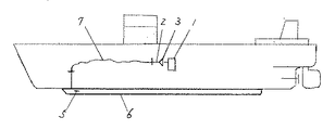
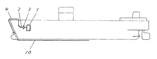
そして、本発明は上記目的を達成するため、第1の課題解決手段の図1から図4は、吃水性より高いところの船腹にエア・コンプレッサーを設置して圧気管を接続し、圧気管には逆止弁を取り付け、また、圧気管には下方に折曲げた中継管を接続し、中継管には高圧空気吹き出し管を接続し、該管の下部を分岐して、竜骨両側の船底に貫通して取り付けたものである。
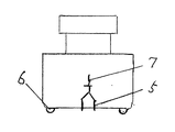
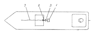
図5から図8は、上記第1の課題解決手段の図1から図4の応用実施例で、平に形成した船底の両側に断面がU字状または半円状の空気抱き込み器を取り付け、また、中継管の代りに、圧気管と高圧空気吹き出し管を耐圧フレシキブルホースで接続し、高圧空気吹き出し管の下端を船底に貫通して船尾方向に折曲げたものである。
なお、空気抱き込み器は他の課題解決手段にも応用実施可能である。In order to achieve the above-mentioned object, the present invention is directed to FIGS. 1 to 4 of the first means for solving the problems. In FIG. Is equipped with a check valve, connected to the pressurized air pipe is a relay pipe bent downward, connected to the relay pipe is a high-pressure air outlet pipe, branches the lower part of the pipe, It is attached through.
FIGS. 5 to 8 show an application example of the first problem solving means shown in FIGS. 1 to 4, in which air traps having a U-shaped or semicircular cross section are attached to both sides of a flat bottom. Further, instead of the relay pipe, the pressure air pipe and the high-pressure air blowing pipe are connected by a pressure-resistant flexible hose, and the lower end of the high-pressure air blowing pipe penetrates the bottom of the ship and is bent in the stern direction.
Note that the air entrainer can be applied to other problem solving means.
第2の課題解決手段の図9から図11は、高圧空気送気管を船内の船底上部に竜骨を夾んで平行に配設して後端を塞ぎ、該管の下面には分岐高圧空気吹き出し管を一定間隔で接続し、該下端を船底に貫通して船尾方向に折曲げたものである。 FIGS. 9 to 11 of the second problem solving means show that a high-pressure air supply pipe is disposed in parallel with the keel in the upper part of the ship bottom to close the rear end, and a branched high-pressure air blowing pipe is provided on the lower surface of the pipe. Are connected at regular intervals, the lower end penetrates the bottom of the ship and is bent in the stern direction.
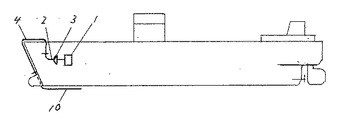
第3の課題解決手段の図12から図14は、就役中のバルバスバウ付の船への取り付け例で、船外高圧空気吹き出し管をバルバスバウに貫通して船尾方向に折曲げ、該先端を船尾方向に分岐して船底に取り付けたものである。
なお、バルバスバウのない船は中継管を舷に沿って配設してもよく、また、中継管はフレシキブルホースを使用してもよい。
図15から図19は、上記第3の課題解決手段の図12から図14の応用実施例で、船外高圧空気吹き出し管を船尾方向に延長して船底に取り付け、該後端を塞ぎ、該管の両側には各高圧空気吹き出し口を一定間隔で開けたものである。FIGS. 12 to 14 of the third problem solving means are examples of attachment to a ship with a barbus bow in service. The high pressure air blow-out pipe passes through the barbus bow and is bent in the stern direction. It is branched to and attached to the bottom of the ship.
In addition, the ship without a Barbus bow may arrange | position a relay pipe along a ridge, and a flexible hose may be used for a relay pipe.
FIGS. 15 to 19 are application examples of FIGS. 12 to 14 of the third problem solving means described above, in which an outboard high-pressure air blowing pipe is extended in the stern direction and attached to the bottom of the ship, the rear end is closed, High-pressure air outlets are opened at regular intervals on both sides of the tube.
以上の高圧空気吹き出し方法は、横方向、船尾方向共船形に応じて適宜増してもよく、船底に貫通して船尾方向に折曲げる代りに溶接エルボを接続してもよい。
また、エア・コンプレッサーは吃水線より高い所であれば、どこに設置してもよく、高圧空気吹き出し管には耐圧フレシキブルホースで接続するようにすれば、自由に設定できるので、簡単な改造工事だけで、本発明を実施することができる。The above-described high-pressure air blowing method may be appropriately increased according to the ship shape in both the lateral direction and the stern direction, and a welding elbow may be connected instead of penetrating through the bottom and bending in the stern direction.
In addition, the air compressor can be installed anywhere as long as it is higher than the flooding line, and if it is connected to the high-pressure air blowing pipe with a pressure-resistant flexible hose, it can be set freely, so only simple remodeling work is required. Thus, the present invention can be implemented.
上記第1の課題解決手段の図1から図4による作用は次の通りである。すなわち、航行時、船底に高圧空気を吹き出せば、船底に空気層ができ、空気は船底に有効に作用し、船底と海水の摩擦抵抗は減ずるので、船足を早めることができる。
第1の課題解決手段の図1から図4の応用実施例の図5から図8は、平底の船底両側に空気抱き込み器を取り付けたので、吹き出された空気は船底に一様に作用し、船速を一層早めることができる。
なお、平底船は浮力が増し、海水につかる部分が少くなるため、航行時に横ずれや進行に不安定さがあるが、船底両側に取り付けた空気抱き込み器が抵抗になって、船の横ずれを防止すると共に船尾方向に空気抱き込み器が進行を良好にすることができる。The operation of the first problem solving means shown in FIGS. 1 to 4 is as follows. That is, when high-pressure air is blown out to the bottom of the ship at the time of navigation, an air layer is formed on the bottom of the ship, the air effectively acts on the bottom of the ship, and the frictional resistance between the ship bottom and seawater is reduced, thereby speeding up the stern.
In FIGS. 5 to 8 of the application example of FIGS. 1 to 4 of the first problem solving means, air traps are attached to both sides of the bottom of the flat bottom so that the blown air acts uniformly on the bottom of the ship. The ship speed can be further increased.
Flat-bottom ships increase in buoyancy and have less contact with seawater.Therefore, there are lateral shifts and instability in navigation, but air traps attached to both sides of the ship become resistance, and In addition to preventing, the air embedder can improve the progress in the stern direction.
第2の課題解決手段の図9から図11は高圧空気を長い範囲で吹き出すので空気層ができやすく、船速を早めることができる。 9 to 11 of the second problem solving means, high pressure air is blown out in a long range, so that an air layer is easily formed and the ship speed can be increased.
第3の課題解決手段の図12から図14は、就役中の船にも取り付けられるので、従来より船速を早めることができる。
第3の課題解決手段の図12から図14の応用実施例の図15から図19は、高圧空気を長い範囲で、各、両側から吹き出すので、空気層ができやすく、船速を一層早めることができる。Since the third problem solving means of FIGS. 12 to 14 are also attached to a ship that is in service, the ship speed can be made faster than before.
12 to 14 of the application example of FIGS. 12 to 14 of the third problem solving means, high pressure air is blown out from both sides in a long range, so that an air layer is easily formed and the ship speed is further increased. Can do.
上述したように、本発明は、航行時、船底に高圧空気を吹き出して空気層を作り、さながら、船を空中滑走状態にして航行するようにしたので、海水の摩擦抵抗を減ずることができる。
したがって、船速を早めることができると共に燃料を相当節約でき、省エネ船として活用することができる。As described above, according to the present invention, when navigating, high-pressure air is blown out to the bottom of the ship to create an air layer, and while the ship is sailing in the air-sliding state, the frictional resistance of seawater can be reduced.
Therefore, the ship speed can be increased, fuel can be saved considerably, and it can be utilized as an energy saving ship.
以下、本発明の実施の形態を説明する。 Embodiments of the present invention will be described below.
第1の課題解決手段の図1から図4において、1は吃水線より高いところの船腹に設置したエア・コンプレッサー、2は該エヤ・コンプレッサー1に接続した圧気管、3は圧気管2に取り付けた逆止弁、4は圧気管2に接続した中継管で下方に折曲げている。5は中継管4に接続した高圧空気吹き出し管で、下部を分岐して竜骨両側の船底に貫通して取り付けている。
図5から図8は、上記第1の課題解決手段の図1から図4の応用実施例で、6は平に形成した船底の両側に取り付けた空気抱き込み器、7は耐圧フレシキブルホースで、中継管4の代りに圧気管2と高圧空気吹き出し管5の中間に接続している。また、高圧空気吹き出し管5の下端を船底に貫通して船尾方向に折曲げている。In FIGS. 1 to 4 of the first problem solving means, 1 is an air compressor installed on the ship's side higher than the inundation line, 2 is a pressure air pipe connected to the
FIGS. 5 to 8 are application examples of FIGS. 1 to 4 of the first problem solving means, wherein 6 is an air entrainer attached to both sides of a flat bottom, 7 is a pressure-resistant flexible hose, Instead of the
第2の課題解決手段の図9から図11において、8は船内の船底上部に竜骨を夾んで平行に配設し、該端を塞いだ高圧空気送気管で、該管の下面に一定間隔で分岐高圧空気吹き出し管9を接続し、該下端を船底に貫通して船尾方向に折曲げている。 In FIGS. 9 to 11 of the second problem solving means,
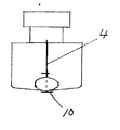
第3の課題解決手段の図12から図14の10はバルバスバウに貫通して船尾方向に折曲げ、該先端を船尾方向に分岐した船外高圧空気吹き出し管で船底に取り付けている。
図15から図19は、上記第3の課題解決手段の図12から図14の応用実施例で、船外高圧空気吹き出し管10を船尾方向に延長して後端を塞ぎ、該管の両側に各一定間隔で、高圧空気吹き出し口11を開けている。
以上において、管はフランジで接続したが、その他適切なものがあればこれを使用してもよい。12 to 14 of the third problem solving means are attached to the bottom of the ship with an outboard high-pressure air blowing pipe that penetrates the Barbasse bow, bends in the stern direction, and divides the tip in the stern direction.
FIGS. 15 to 19 show an application example of FIGS. 12 to 14 of the third problem solving means. The outboard high-pressure
In the above, the pipes are connected by flanges, but any other suitable ones may be used.
以下、上記構成の動作を説明する。本装置は航行時に作動し、しけの時は作動しない。
なお、しけの時、激しいローリングやピッチングが発生して、高圧空気吹き出し管や船外高圧空気吹き出し管等に逆圧がかかり、海水が逆流しても逆止弁が阻止する安全対策を構じているので、エア・コンプレッサーは損傷しない。The operation of the above configuration will be described below. This device operates on sailing and does not operate on barges.
In the event of barges, there is a safety measure to prevent the check valve from blocking even if seawater flows backward due to the occurrence of intense rolling or pitching, applying back pressure to the high-pressure air blowing pipe or outboard high-pressure air blowing pipe, etc. The air compressor will not be damaged.
1 エア・コンプレッサー
2 圧気管
3 逆止弁
4 中継管
5 高圧空気吹き出し管
6 空気抱き込み器
7 耐圧フレシキブルホース
8 高圧空気送気管
9 分岐高圧空気吹き出し管
10 船外高圧空気吹き出し管
11 高圧空気吹き出し口DESCRIPTION OF SYMBOLS 1
Claims (3)
Priority Applications (1)
| Application Number | Priority Date | Filing Date | Title |
|---|---|---|---|
| JP2014102811A JP2015199480A (en) | 2014-04-06 | 2014-04-06 | Energy saving vessel whose speed is increased by reducing friction resistance of sea water |
Applications Claiming Priority (1)
| Application Number | Priority Date | Filing Date | Title |
|---|---|---|---|
| JP2014102811A JP2015199480A (en) | 2014-04-06 | 2014-04-06 | Energy saving vessel whose speed is increased by reducing friction resistance of sea water |
Publications (1)
| Publication Number | Publication Date |
|---|---|
| JP2015199480A true JP2015199480A (en) | 2015-11-12 |
Family
ID=54551169
Family Applications (1)
| Application Number | Title | Priority Date | Filing Date |
|---|---|---|---|
| JP2014102811A Pending JP2015199480A (en) | 2014-04-06 | 2014-04-06 | Energy saving vessel whose speed is increased by reducing friction resistance of sea water |
Country Status (1)
| Country | Link |
|---|---|
| JP (1) | JP2015199480A (en) |
Citations (8)
| Publication number | Priority date | Publication date | Assignee | Title |
|---|---|---|---|---|
| JPS4898590A (en) * | 1972-03-28 | 1973-12-14 | ||
| JPS60163784A (en) * | 1984-02-07 | 1985-08-26 | Kazu Tanabe | Ship with air exhaust nozzles at bottom |
| JPH107070A (en) * | 1996-06-19 | 1998-01-13 | Mitsui Eng & Shipbuild Co Ltd | Air supply system for submerged hull |
| JPH11198892A (en) * | 1998-01-16 | 1999-07-27 | Koichi Jinno | Boat reducing frictional resistance |
| JP2006514896A (en) * | 2002-05-07 | 2006-05-18 | ディーケー・グループ・エヌ.エー. エヌ.ブイ. | Air cavity ship having wedge-shaped cavities, longitudinally displaced cavities, and rotation control means, and a method of building the air cavity ship |
| US20090233502A1 (en) * | 2008-03-12 | 2009-09-17 | Wellman Jack G | Friction reducing pollution control system for marine vehicles |
| JP2009292202A (en) * | 2008-06-03 | 2009-12-17 | Zuei-Ling Lin | Method for reducing frictional resistance force between ship body and water |
| JP2012224108A (en) * | 2011-04-15 | 2012-11-15 | Mitsubishi Heavy Ind Ltd | Frictional resistance reduction type ship |
-
2014
- 2014-04-06 JP JP2014102811A patent/JP2015199480A/en active Pending
Patent Citations (8)
| Publication number | Priority date | Publication date | Assignee | Title |
|---|---|---|---|---|
| JPS4898590A (en) * | 1972-03-28 | 1973-12-14 | ||
| JPS60163784A (en) * | 1984-02-07 | 1985-08-26 | Kazu Tanabe | Ship with air exhaust nozzles at bottom |
| JPH107070A (en) * | 1996-06-19 | 1998-01-13 | Mitsui Eng & Shipbuild Co Ltd | Air supply system for submerged hull |
| JPH11198892A (en) * | 1998-01-16 | 1999-07-27 | Koichi Jinno | Boat reducing frictional resistance |
| JP2006514896A (en) * | 2002-05-07 | 2006-05-18 | ディーケー・グループ・エヌ.エー. エヌ.ブイ. | Air cavity ship having wedge-shaped cavities, longitudinally displaced cavities, and rotation control means, and a method of building the air cavity ship |
| US20090233502A1 (en) * | 2008-03-12 | 2009-09-17 | Wellman Jack G | Friction reducing pollution control system for marine vehicles |
| JP2009292202A (en) * | 2008-06-03 | 2009-12-17 | Zuei-Ling Lin | Method for reducing frictional resistance force between ship body and water |
| JP2012224108A (en) * | 2011-04-15 | 2012-11-15 | Mitsubishi Heavy Ind Ltd | Frictional resistance reduction type ship |
Similar Documents
| Publication | Publication Date | Title |
|---|---|---|
| JP5599482B1 (en) | Ship equipped with bubble resistance reduction device and ship resistance reduction method | |
| UA117143C2 (en) | Vessel having an improved hull shape | |
| CN101574996A (en) | Method for reducing friction resistance between ship body and water by utilizing gas released in water | |
| CN104340331A (en) | Device for reducing navigation resistance on ship with moon pool | |
| CN204623773U (en) | A kind of hawse pipe structure of boats and ships | |
| JP6484906B2 (en) | Ships with a structure that reduces resistance when sailing | |
| CN108343030A (en) | A kind of jet stream and air bubble breakwater and its wave absorption method of adjust automatically flow direction | |
| CN205707157U (en) | A kind of boats and ships ice navigation ballast tank winterization system | |
| CN205365975U (en) | Reduce additional fin keel and scientific investigation ship that bubble disturbed | |
| GB2508027A (en) | Gas bubble hull lubrication system | |
| JP5624128B2 (en) | A ship equipped with a crosswind power generator | |
| US20260015064A1 (en) | System and method for reducing drag on the hull of a vessel | |
| RU2017123064A (en) | METHOD AND SYSTEM FOR CARRYING OUT LOADS OF FLUID IN THE OPEN SEA | |
| KR20140048287A (en) | Marine vessel operating in ice-covered waters | |
| CN106477013A (en) | The Multi-direction movable ship that a kind of diversion is carried out | |
| CN103129698A (en) | Full circle swinging tug | |
| JP5806251B2 (en) | Ship equipped with bubble resistance reduction device and ship resistance reduction method | |
| CN104603003A (en) | Method and device for reducing hydrodynamic water resistance of a vessel | |
| JP2009292202A (en) | Method for reducing frictional resistance force between ship body and water | |
| CN102849195B (en) | A kind of Guide pipe device for stem | |
| RU2540156C1 (en) | Wave propulsor sail-mesh | |
| TWI374103B (en) | ||
| JP2015182762A (en) | Principle of ship propulsion force reduction device | |
| RU2859013C1 (en) | Submersible vehicle with device for supplying atmospheric air and removing exhaust gases | |
| US1093692A (en) | Ship construction. |
Legal Events
| Date | Code | Title | Description |
|---|---|---|---|
| A02 | Decision of refusal |
Free format text: JAPANESE INTERMEDIATE CODE: A02 Effective date: 20151006 |