JP2016014351A - エンジンの動弁構造 - Google Patents
エンジンの動弁構造 Download PDFInfo
- Publication number
- JP2016014351A JP2016014351A JP2014136626A JP2014136626A JP2016014351A JP 2016014351 A JP2016014351 A JP 2016014351A JP 2014136626 A JP2014136626 A JP 2014136626A JP 2014136626 A JP2014136626 A JP 2014136626A JP 2016014351 A JP2016014351 A JP 2016014351A
- Authority
- JP
- Japan
- Prior art keywords
- cam
- tappet
- center line
- valve
- end wall
- Prior art date
- Legal status (The legal status is an assumption and is not a legal conclusion. Google has not performed a legal analysis and makes no representation as to the accuracy of the status listed.)
- Granted
Links
Images

Landscapes
- Valve-Gear Or Valve Arrangements (AREA)
Abstract
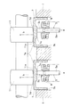
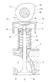
【解決手段】軸状のバルブステム5bの一端にバルブの弁孔に接離する傘部5aが設けられるバルブ部材5と、バルブステム5bの他端に設けられその他端5bが当接する端壁部7aとその端壁部7aの周縁から傘部5a側へ立ち上がる周壁部7bとからなるタペット7と、タペット7の端壁部7aの外面7dに摺接するカムローブ11が設けられたカムシャフトとを備え、カムローブ11におけるカムシャフトSの軸方向に対する各カムローブ中心線cを、タペット7の端壁部7aの外面7dの中心を通る端壁部外面中心線bに対して、カムシャフトSの軸方向に沿って偏心させ、バルブステムの軸心aを、タペット7の端壁部外面中心線bに対して、カムローブ中心線cが偏心する側と逆側に配置したエンジンの動弁構造とした。
【選択図】図1
Description
このような荷重の偏りは、タペットの円滑な回転を阻害し、カムローブやタペットに偏摩耗を発生させる原因となる場合がある。
タペット7に対してカムローブ11をオフセットさせたことに伴い、バルブステム5bをカムローブ11とは反対側へオフセットし、過大な荷重が一箇所に集中することを回避したことが、タペット7の回転を円滑にする上で有効に作用している。
2 燃焼室
3 ポート
4 弁孔
5 バルブ部材(バルブ)
5a 傘部
5b バルブステム
5c ステムエンド
7 タペット
7a 端壁部
7b 周壁部
7d 外面
10 シャフト部材
11 カムローブ
11a カム面
12 カム部材
13 キー
14 カムジャーナル
20 カムジャーナルキャップ
S カムシャフト
Claims (5)
- 軸状のバルブステムの一端にバルブの弁孔に接離する傘部が設けられるバルブ部材と、
前記バルブステムの他端に設けられ前記他端が当接する端壁部とその端壁部の周縁から前記傘部側へ立ち上がる周壁部とからなるタペットと、
前記タペットの端壁部外面に摺接するカムローブが設けられたカムシャフトとを備え、
前記カムローブにおける前記カムシャフトの軸方向に対するカムローブ中心線を、前記タペットの前記端壁部外面の中心を通る端壁部外面中心線に対して、前記カムシャフトの軸方向に沿って偏心させ、
前記バルブステムの軸心を、前記タペットの前記端壁部外面中心線に対して、前記カムローブ中心線が偏心する側と逆側に配置したエンジンの動弁構造。 - 前記カムシャフトは吸気側と排気側にそれぞれ設けられ、
前記各カムシャフトは少なくとも一つのカムローブを備えており、
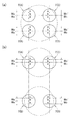
吸気側の前記カムシャフトは、前記カムローブのカムローブ中心線を、対応する前記タペットの端壁部外面中心線に対して、前記カムシャフトの軸方向に沿って一方向に偏心させて配置され、
排気側の前記カムシャフトは、前記カムローブのカムローブ中心線を、対応する前記タペットの端壁部外面中心線に対して、前記カムシャフトの軸方向に沿って他方向に偏心させて配置されている請求項1に記載のエンジンの動弁構造。 - 前記カムシャフトは吸気側と排気側にそれぞれ設けられ、
前記各カムシャフトは同一の気筒に対応する複数のカムローブを備えており、
吸気側の前記カムシャフトは、前記複数のカムローブの各カムローブ中心線を、対応する前記タペットの端壁部外面中心線に対して、それぞれ前記カムシャフトの軸方向に沿って一方向に偏心させて配置され、
排気側の前記カムシャフトは、前記複数のカムローブの各カムローブ中心線を、対応する前記タペットの端壁部外面中心線に対して、それぞれ前記カムシャフトの軸方向に沿って他方向に偏心させて配置されている請求項1に記載のエンジンの動弁構造。 - 前記タペットの前記端壁部外面は中央部が外周部よりも凸に形成されている請求項1から3の何れか1項に記載のエンジンの動弁構造。
- 前記カムローブのカム面は前記カムシャフトの軸方向における中央部が両端部よりも凸に形成されている請求項1から4の何れか1項に記載のエンジンの動弁構造。
Priority Applications (1)
| Application Number | Priority Date | Filing Date | Title |
|---|---|---|---|
| JP2014136626A JP6327018B2 (ja) | 2014-07-02 | 2014-07-02 | エンジンの動弁構造 |
Applications Claiming Priority (1)
| Application Number | Priority Date | Filing Date | Title |
|---|---|---|---|
| JP2014136626A JP6327018B2 (ja) | 2014-07-02 | 2014-07-02 | エンジンの動弁構造 |
Publications (2)
| Publication Number | Publication Date |
|---|---|
| JP2016014351A true JP2016014351A (ja) | 2016-01-28 |
| JP6327018B2 JP6327018B2 (ja) | 2018-05-23 |
Family
ID=55230727
Family Applications (1)
| Application Number | Title | Priority Date | Filing Date |
|---|---|---|---|
| JP2014136626A Expired - Fee Related JP6327018B2 (ja) | 2014-07-02 | 2014-07-02 | エンジンの動弁構造 |
Country Status (1)
| Country | Link |
|---|---|
| JP (1) | JP6327018B2 (ja) |
Cited By (1)
| Publication number | Priority date | Publication date | Assignee | Title |
|---|---|---|---|---|
| CN107084013A (zh) * | 2017-06-21 | 2017-08-22 | 浙江春风动力股份有限公司 | 发动机及其凸轮轴组件 |
Citations (5)
| Publication number | Priority date | Publication date | Assignee | Title |
|---|---|---|---|---|
| JPS61122307U (ja) * | 1985-01-21 | 1986-08-01 | ||
| JPH0687605U (ja) * | 1993-06-01 | 1994-12-22 | ダイハツ工業株式会社 | 内燃機関における動弁装置 |
| JPH08128308A (ja) * | 1994-10-31 | 1996-05-21 | Mazda Motor Corp | エンジンの吸気装置 |
| JP2004218438A (ja) * | 2003-01-09 | 2004-08-05 | Nissan Motor Co Ltd | 火花点火式内燃機関の燃焼室構造 |
| JP2012072671A (ja) * | 2010-09-28 | 2012-04-12 | Hitachi Automotive Systems Ltd | 内燃機関のバルブリフタ |
-
2014
- 2014-07-02 JP JP2014136626A patent/JP6327018B2/ja not_active Expired - Fee Related
Patent Citations (5)
| Publication number | Priority date | Publication date | Assignee | Title |
|---|---|---|---|---|
| JPS61122307U (ja) * | 1985-01-21 | 1986-08-01 | ||
| JPH0687605U (ja) * | 1993-06-01 | 1994-12-22 | ダイハツ工業株式会社 | 内燃機関における動弁装置 |
| JPH08128308A (ja) * | 1994-10-31 | 1996-05-21 | Mazda Motor Corp | エンジンの吸気装置 |
| JP2004218438A (ja) * | 2003-01-09 | 2004-08-05 | Nissan Motor Co Ltd | 火花点火式内燃機関の燃焼室構造 |
| JP2012072671A (ja) * | 2010-09-28 | 2012-04-12 | Hitachi Automotive Systems Ltd | 内燃機関のバルブリフタ |
Cited By (1)
| Publication number | Priority date | Publication date | Assignee | Title |
|---|---|---|---|---|
| CN107084013A (zh) * | 2017-06-21 | 2017-08-22 | 浙江春风动力股份有限公司 | 发动机及其凸轮轴组件 |
Also Published As
| Publication number | Publication date |
|---|---|
| JP6327018B2 (ja) | 2018-05-23 |
Similar Documents
| Publication | Publication Date | Title |
|---|---|---|
| JP4883330B2 (ja) | 内燃機関の可変動弁装置 | |
| US20150096514A1 (en) | Positive control (desmodromic) valve systems for internal combustion engines | |
| US20180094553A1 (en) | Valve bridge for valve systems | |
| US7913658B2 (en) | Valve actuating mechanism for an internal combustion engine, and cylinder head incorporating same | |
| AU2015234634B2 (en) | Pivoting variable cam follower | |
| JP6327018B2 (ja) | エンジンの動弁構造 | |
| JP5252946B2 (ja) | 動弁機構 | |
| JP6005939B2 (ja) | 可変動弁装置 | |
| JP2750415B2 (ja) | 多弁式エンジンの動弁装置 | |
| JP6387663B2 (ja) | エンジンの動弁構造 | |
| US7938089B2 (en) | Valve actuating mechanism for an internal combustion engine, and cylinder head incorporating same | |
| US8794204B2 (en) | Valvetrain for overhead valve engine | |
| JP5278702B2 (ja) | 内燃機関の可変動弁装置 | |
| CN104285043B (zh) | 键销、气门挺杆组件及内燃发动机 | |
| US11352915B2 (en) | Cylinder head | |
| JP7721962B2 (ja) | 内燃機関 | |
| JP4566071B2 (ja) | 内燃機関 | |
| JP2007138795A (ja) | カムキャップ、ならびにそれを用いたカムシャフト支持構造 | |
| JP6179348B2 (ja) | 動弁機構と内燃機関 | |
| JP2007205299A (ja) | 内燃機関のシリンダヘッド | |
| JP6281235B2 (ja) | エンジンの動弁装置 | |
| JP2007239496A (ja) | 内燃機関のシリンダヘッド | |
| JP2015183530A (ja) | エンジンの動弁装置 | |
| KR101646133B1 (ko) | 실린더 휴지 엔진 | |
| JP2002129913A (ja) | 4サイクルエンジンの動弁機構 |
Legal Events
| Date | Code | Title | Description |
|---|---|---|---|
| A621 | Written request for application examination |
Free format text: JAPANESE INTERMEDIATE CODE: A621 Effective date: 20170623 |
|
| TRDD | Decision of grant or rejection written | ||
| A977 | Report on retrieval |
Free format text: JAPANESE INTERMEDIATE CODE: A971007 Effective date: 20180314 |
|
| A01 | Written decision to grant a patent or to grant a registration (utility model) |
Free format text: JAPANESE INTERMEDIATE CODE: A01 Effective date: 20180320 |
|
| A61 | First payment of annual fees (during grant procedure) |
Free format text: JAPANESE INTERMEDIATE CODE: A61 Effective date: 20180402 |
|
| R151 | Written notification of patent or utility model registration |
Ref document number: 6327018 Country of ref document: JP Free format text: JAPANESE INTERMEDIATE CODE: R151 |
|
| S531 | Written request for registration of change of domicile |
Free format text: JAPANESE INTERMEDIATE CODE: R313531 |
|
| R350 | Written notification of registration of transfer |
Free format text: JAPANESE INTERMEDIATE CODE: R350 |
|
| LAPS | Cancellation because of no payment of annual fees |