JP2016102771A - Liquid leakage sensor - Google Patents
Liquid leakage sensor Download PDFInfo
- Publication number
- JP2016102771A JP2016102771A JP2014242632A JP2014242632A JP2016102771A JP 2016102771 A JP2016102771 A JP 2016102771A JP 2014242632 A JP2014242632 A JP 2014242632A JP 2014242632 A JP2014242632 A JP 2014242632A JP 2016102771 A JP2016102771 A JP 2016102771A
- Authority
- JP
- Japan
- Prior art keywords
- liquid
- sensor
- holder
- leakage sensor
- absorbent sheet
- Prior art date
- Legal status (The legal status is an assumption and is not a legal conclusion. Google has not performed a legal analysis and makes no representation as to the accuracy of the status listed.)
- Pending
Links
- 239000007788 liquid Substances 0.000 title claims abstract description 159
- 239000013307 optical fiber Substances 0.000 claims abstract description 15
- 239000002250 absorbent Substances 0.000 claims description 32
- 230000002745 absorbent Effects 0.000 claims description 23
- 238000001514 detection method Methods 0.000 claims description 23
- 238000009736 wetting Methods 0.000 claims 1
- 238000010586 diagram Methods 0.000 description 4
- XLYOFNOQVPJJNP-UHFFFAOYSA-N water Substances O XLYOFNOQVPJJNP-UHFFFAOYSA-N 0.000 description 4
- 238000009434 installation Methods 0.000 description 3
- 230000002093 peripheral effect Effects 0.000 description 3
- 238000000034 method Methods 0.000 description 2
- LFQSCWFLJHTTHZ-UHFFFAOYSA-N Ethanol Chemical compound CCO LFQSCWFLJHTTHZ-UHFFFAOYSA-N 0.000 description 1
- 238000010521 absorption reaction Methods 0.000 description 1
- 239000003929 acidic solution Substances 0.000 description 1
- 239000000853 adhesive Substances 0.000 description 1
- 230000001070 adhesive effect Effects 0.000 description 1
- 239000012670 alkaline solution Substances 0.000 description 1
- 125000004122 cyclic group Chemical group 0.000 description 1
- 239000002360 explosive Substances 0.000 description 1
- 239000000835 fiber Substances 0.000 description 1
- 238000005187 foaming Methods 0.000 description 1
- 238000002386 leaching Methods 0.000 description 1
- 230000014759 maintenance of location Effects 0.000 description 1
- 239000000463 material Substances 0.000 description 1
- 239000000203 mixture Substances 0.000 description 1
- 239000004745 nonwoven fabric Substances 0.000 description 1
- 239000003921 oil Substances 0.000 description 1
- 239000003960 organic solvent Substances 0.000 description 1
- 239000011347 resin Substances 0.000 description 1
- 229920005989 resin Polymers 0.000 description 1
- 230000035945 sensitivity Effects 0.000 description 1
- -1 thinner Substances 0.000 description 1
- 238000002834 transmittance Methods 0.000 description 1
- 239000002759 woven fabric Substances 0.000 description 1
Images








Landscapes
- Examining Or Testing Airtightness (AREA)
Abstract
Description
本発明は、光ファイバで媒体の屈折率の変化を検出することにより液体を検知する漏液センサに関する。 The present invention relates to a liquid leakage sensor that detects a liquid by detecting a change in the refractive index of a medium using an optical fiber.
水、酸性溶液、アルカリ溶液等の水性液体や、アルコール、シンナー、ガソリン等の油性液体の漏液を検出する漏液センサとして、薄紙が液体を吸収することにより薄紙の透過率又は反射率が変化することを利用した漏液センサが知られている(特許文献1)。この漏液センサにおいて、薄紙への投受光を光ファイバによって行うと、引火性又は爆発性の液体に対しても安全に漏液を検知することができる。 As a leak sensor for detecting leaks of water-based liquids such as water, acidic solutions, and alkaline solutions, and oil-based liquids such as alcohol, thinner, and gasoline, the thin paper absorbs the liquid and the transmittance or reflectance of the thin paper changes. A liquid leakage sensor utilizing this is known (Patent Document 1). In this liquid leakage sensor, when light is projected and received on a thin paper using an optical fiber, the liquid leakage can be detected safely even for a flammable or explosive liquid.
しかしながら、この漏水センサではホルダに光の投光部と受光部を設け、薄紙に透光したときの反射光又は透過光を観察するためにホルダの底面積も高さも大きくなり、漏水センサを狭い間隙に設置することができない。実際、このタイプの実用機のホルダは底面の径が30mm以上、高さが14mm以上である。 However, in this water leakage sensor, a light projecting portion and a light receiving portion are provided in the holder, and the bottom area and height of the holder are increased in order to observe the reflected light or transmitted light transmitted through the thin paper, and the water leakage sensor is narrow. It cannot be installed in the gap. In fact, the holder of this type of practical machine has a bottom diameter of 30 mm or more and a height of 14 mm or more.
一方、光ファイバのコアを露出させて湾曲し、その湾曲部が接液したときに検出される屈折率の変化から液体を検知したり、液体組成を測定したりする液体センサが知られている(特許文献2)。
しかしながら、この液体センサでは光ファイバの湾曲部を液体内に入れなければならないので、微量の液漏れの検出には使用することができない。
On the other hand, there is known a liquid sensor that detects a liquid from a change in refractive index detected when an optical fiber core is exposed and the curved portion comes into contact with liquid, or measures a liquid composition. (Patent Document 2).
However, this liquid sensor cannot be used for detecting a small amount of liquid leakage because the curved portion of the optical fiber must be put in the liquid.
上述の従来技術に対し、本発明の課題は、狭い間隙にも設置することができ、僅かな漏液も検知することのできる漏液センサを提供することにある。 The subject of this invention with respect to the above-mentioned prior art is providing the leak sensor which can be installed also in a narrow gap | interval and can detect a slight leak.
本発明者は、屈折率の変化を光ファイバの湾曲部で検出することで液体を検知するにあたり、その検知部となる光ファイバの湾曲部をホルダで保護し、かつそのホルダに集液手段を付加し、集液手段で集められた液体に検知部を接液させると上述の課題を解決できることを見出し、本発明を想到した。 The present inventor detects a liquid by detecting a change in refractive index with a curved portion of an optical fiber, and protects the curved portion of the optical fiber serving as the detection portion with a holder, and a liquid collecting means on the holder. In addition, the inventors have found that the above-described problems can be solved by bringing the detection unit into contact with the liquid collected by the liquid collecting means, and have arrived at the present invention.
即ち、本発明は、光ファイバの湾曲部で形成されたセンサ部が接液することで検出される屈折率の変化により液体を検知する漏液センサであって、センサ部を保持するホルダ、検知すべき液体を集液してセンサ部を濡らす集液手段を有する漏液センサを提供する。 That is, the present invention is a liquid leakage sensor that detects a liquid by a change in refractive index detected by contact of a sensor portion formed by a curved portion of an optical fiber, and a holder that holds the sensor portion, Provided is a liquid leakage sensor having liquid collecting means for collecting liquid to be wetted to wet a sensor unit.
本発明の漏液センサによれば、ホルダが備える集液手段が液体の検知対象面の液体を集液し、その液体でセンサ部が濡れることにより液体の検知対象面の液体が検知される。したがって、液体の検知対象面に集液手段を薄く広げることで僅かな液体でも検知することが可能となる。 According to the liquid leakage sensor of the present invention, the liquid collecting means included in the holder collects the liquid on the liquid detection target surface, and the liquid on the liquid detection target surface is detected by the sensor unit getting wet with the liquid. Accordingly, even a small amount of liquid can be detected by thinly spreading the liquid collecting means on the liquid detection target surface.
また、集液手段としては吸液性シート等を使用することができ、かつ液体の検知は光ファイバで屈折率の変化を検出することにより行うので、集液手段もセンサ部も薄型にコンパクトに形成することができる。したがって、狭い間隙にも漏液センサを取り付けることが可能となる。また、液体の検知を光ファイバで行うので、検知すべき液体が有機溶剤等である場合の防爆要求にも応じることができる。 In addition, a liquid-absorbing sheet or the like can be used as the liquid collecting means, and the liquid is detected by detecting a change in the refractive index with an optical fiber, so that the liquid collecting means and the sensor section are both thin and compact. Can be formed. Therefore, it is possible to attach a leak sensor to a narrow gap. Further, since the liquid is detected by the optical fiber, it is possible to meet the explosion-proof request when the liquid to be detected is an organic solvent or the like.
以下、図面を参照しつつ本発明を具体的に説明する。なお、各図中、同一符号は同一又は同等の構成要素を表している。 Hereinafter, the present invention will be specifically described with reference to the drawings. In each figure, the same numerals indicate the same or equivalent components.
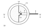
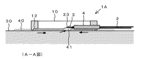
図1Aは、本発明の一実施例の漏液センサ1Aの部品図であり、図1Bは、図1Aに示した部品から形成した漏液センサ1Aの上面図であり、図2は、その使用状態の断面図である。 1A is a component diagram of a leak sensor 1A according to an embodiment of the present invention, FIG. 1B is a top view of the leak sensor 1A formed from the components shown in FIG. 1A, and FIG. It is sectional drawing of a state.
この漏液センサ1Aは、コアとクラッドからなる光ファイバ2のコアが露出して湾曲している湾曲部をセンサ部3とし、このセンサ部3が接液することで検出される屈折率の変化から液体の存在を検知する。
In this liquid leak sensor 1A, a curved portion where the core of the
センサ部3としては、特許文献2等に記載されている公知の光ファイバの湾曲部からなる漏液センサのセンサ部を使用することができる。
As the
センサ部3は、該センサ部3を外力から保護するホルダ10に保持される。より具体的には、本実施例においてセンサ部3はその湾曲形状を保持するために固定用部材4に取り付けられる。また、ホルダ10は概略環状の外形を有し、周壁に切欠部11が形成され、一方の開口縁部に段部12が形成されている。そして、センサ部3の固定用部材4がホルダ10の切欠部11に嵌め込まれることで固定される。
The
本発明においてホルダの形状や大きさに特に限定はないが、本実施例のホルダ10は、例えば、外形10〜50mm、厚さ2〜10mmとすることができる。
Although there is no limitation in particular in the shape and magnitude | size of a holder in this invention, the
ホルダ10には、検知すべき液体を集液してセンサ部3を濡らす集液手段20として吸液性シート21が着脱自在に取り付けられる。
A liquid
吸液性シート21の形成材料としては、液体の吸収、保液又は浸出作用のある薄紙、不織布、織布、連続起泡を有する樹脂シート等を使用することができ、より具体的には、例えば旭化成せんい株式会社製の(登録商標)「ベンコット」シリーズ等を使用することができる。
As a material for forming the liquid-
吸液性シート21は、ホルダ10の段部12内に嵌められる円形の外形を有し、切込22により舌片状の浮き上がり部23が中央部に形成されている。吸液性シート21の厚さは、例えば0.2〜2mmとすることができる。
The liquid-
図1B及び図2に示すように、センサ部3と吸液性シート21をホルダ10に取り付けるあたり、吸液性シート21は、該吸液性シート21が液体の検知対象面30と接触するようにホルダ10の段部12に嵌められ、また、液体の検知対象面30と吸液性シート21の浮き上がり部23とでセンサ部3が挟まれるようにする。
As shown in FIGS. 1B and 2, when the
漏液センサ1Aの使用方法としては、このように組み立てた漏液センサ1Aを液体の検知対象面30に置く。液体の検知対象面30上に液体40が存在すると、液体40は吸液性シート21に吸液され、毛管現象により図2に矢印で示したように浸透し、吸液性シート21の浮き上がり部23に達し、センサ部3を濡らす。これにより、液体40を検知することができる。特に、吸液性シート21による吸液量が十分であると、液体の検知対象面30と浮き上がり部23との間に液滴41が溜まり、センサ部3が液滴41の中に挿入された状態となる。これにより、より確実に液体40を検知することができる。
As a method of using the liquid leakage sensor 1A, the liquid leakage sensor 1A assembled in this way is placed on the liquid
なお、一旦、液体40を吸液した吸液性シート21は、新たな吸液性シート21に交換される。
The liquid
本発明は、種々の態様をとることができる。
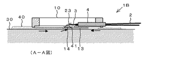
例えば、図3A、図3Bに示すように、上述の漏液センサ1Aに対して吸液性シート21の押さえ部材13を組み合わせてもよい。この押さえ部材13は中央部に凸部14を有し、外周部から突出した突出片15のバネ性によりホルダ10の外周に着脱自在に固定される。
The present invention can take various aspects.
For example, as shown in FIGS. 3A and 3B, the pressing
図4に示すように、漏液センサ1Bの使用状態において、押さえ部材13の中央部は液体の検知対象面30と吸液性シート21との間に位置し、吸液性シート21の浮き上がり部23を上方に押し上げる。これにより、吸液性シート21が吸液すると、浮き上がり部23に液滴41が溜まりやすくなるので好ましい。
As shown in FIG. 4, in the usage state of the
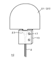
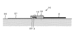
本発明において、ホルダ10や吸液性シート21の形状に特に制限はなく、ホルダ10における吸液性シート21の取り付け方にも制限はない。例えば、図5A、図5Bに示す漏液センサ1Cでは、ホルダ10の端部に形成された凹部16内にセンサ部3が位置するように、センサ部3近傍の光ファイバ2がホルダ10に埋め込まれており、ホルダ10にセンサ部3の湾曲形状を固定する機能と、センサ部3を外力から保護する機能をもたせている。
In this invention, there is no restriction | limiting in particular in the shape of the
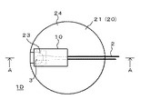
また、この漏液センサ1Cでは、吸液性シート21の一端に舌片状部分を突出させることにより浮き上がり部23が形成されており、漏液センサ1Cの使用状態では、図5Bに示すように、吸液性シート21の浮き上がり部23がホルダ10の凹部16に挿入される。このため、吸液性シート21の全体形状は、ホルダ10の形状や大きさに関わらず、漏液検知の目的や漏液センサの設置場所等に応じてホルダ10外に任意に広げることができる。例えば、図7に示す漏液センサ1Dのように吸液性シート21の全体形状を円形にしてもよく、図8に示す漏液センサ1Eのように矩形にしてもよく、図9に示す漏液センサ1Fのように環状にしてもよい。
Further, in this
また、漏液センサ1Cのホルダ10には、該ホルダ10を液体の検知対象面に必要に応じて固定できるように、ネジ、ボルト、鋲等の固定用部材を通す貫通孔17が設けられている。そのため、例えば、図6Aに示すように、水平な液体の検知対象面30に対して吸液性シート21とホルダ10の接地面が沿うようにホルダ10を固定用部材18で固定してもよく、図6Bに示すように、水平な液体の検知対象面30に対して吸液性シート21は沿わせるが、ホルダ10の接地面は鉛直な壁面31に沿うようにホルダ10を固定してもよい。
Further, the
このように本発明の漏液センサによれば、吸液性シートで液体を吸液できる限り、漏液センサの設置場所や設置方向を任意に定めることができる。 As described above, according to the liquid leakage sensor of the present invention, the installation location and the installation direction of the liquid leakage sensor can be arbitrarily determined as long as the liquid can be absorbed by the liquid absorbent sheet.
また、吸液性シートを備えた本発明の漏液センサの使用態様において、図10に示すように、漏液センサ1Dの吸液性シート21の浮き上がり部23を折り返し、センサ部3が吸液性シート21の浮き上がり部23と本体部24とで挟まれるようにしてもよい。漏液検知の感度の点からは吸液性シートと検知対象面とでセンサ部を挟むのが好ましい。
Further, in the usage mode of the liquid leakage sensor of the present invention provided with the liquid absorbent sheet, as shown in FIG. 10, the floating
さらに、本発明においては、吸液性シート21を省略し、集液手段20をホルダ10自体に形成してもよい。例えば、図12A、図12Bに示す漏液センサ1Gのように、液体の検知対象面に対するホルダ10の接地面に集液手段20として導液溝19を形成してもよい。この漏液センサ1Gでは、ホルダ10の外周部から、凹部16に取り付けられたセンサ部3方向へ液体が誘導されるように導液溝19が放射状に形成されている。
Further, in the present invention, the liquid
1A、1B、1C、1D、1E、1F、1G 漏液センサ
2 光ファイバ
3 センサ部
4 固定用部材
10 ホルダ
11 切欠部
12 段部
13 押さえ部材
14 凸部
15 突出片
16 凹部
17 貫通孔
18 固定用部材
19 導液溝
20 集液手段
21 吸液性シート
22 切込
23 浮き上がり部
24 本体部
30 液体の検知対象面
31 鉛直な壁面
40 液体
41 液滴
1A, 1B, 1C, 1D, 1E, 1F,
Claims (5)
Priority Applications (1)
| Application Number | Priority Date | Filing Date | Title |
|---|---|---|---|
| JP2014242632A JP2016102771A (en) | 2014-11-29 | 2014-11-29 | Liquid leakage sensor |
Applications Claiming Priority (1)
| Application Number | Priority Date | Filing Date | Title |
|---|---|---|---|
| JP2014242632A JP2016102771A (en) | 2014-11-29 | 2014-11-29 | Liquid leakage sensor |
Publications (1)
| Publication Number | Publication Date |
|---|---|
| JP2016102771A true JP2016102771A (en) | 2016-06-02 |
Family
ID=56088050
Family Applications (1)
| Application Number | Title | Priority Date | Filing Date |
|---|---|---|---|
| JP2014242632A Pending JP2016102771A (en) | 2014-11-29 | 2014-11-29 | Liquid leakage sensor |
Country Status (1)
| Country | Link |
|---|---|
| JP (1) | JP2016102771A (en) |
Cited By (3)
| Publication number | Priority date | Publication date | Assignee | Title |
|---|---|---|---|---|
| JP2018130858A (en) * | 2017-02-14 | 2018-08-23 | セイコーエプソン株式会社 | Liquid ejector |
| JP2022500622A (en) * | 2018-08-10 | 2022-01-04 | トルマー、ヨハン | Devices and methods for detecting leaks |
| CN114127529A (en) * | 2019-07-10 | 2022-03-01 | 藤仓复合材料科技株式会社 | Liquid detection sensor |
Citations (4)
| Publication number | Priority date | Publication date | Assignee | Title |
|---|---|---|---|---|
| JPS54180791U (en) * | 1978-06-12 | 1979-12-21 | ||
| JPS6031654U (en) * | 1983-08-10 | 1985-03-04 | 昭和電線電纜株式会社 | liquid detector |
| JP2002296141A (en) * | 2001-03-30 | 2002-10-09 | T & T:Kk | Liquid leakage sensor |
| JP2012037453A (en) * | 2010-08-10 | 2012-02-23 | Ihi Scube:Kk | Liquid detector and liquid identification system |
-
2014
- 2014-11-29 JP JP2014242632A patent/JP2016102771A/en active Pending
Patent Citations (4)
| Publication number | Priority date | Publication date | Assignee | Title |
|---|---|---|---|---|
| JPS54180791U (en) * | 1978-06-12 | 1979-12-21 | ||
| JPS6031654U (en) * | 1983-08-10 | 1985-03-04 | 昭和電線電纜株式会社 | liquid detector |
| JP2002296141A (en) * | 2001-03-30 | 2002-10-09 | T & T:Kk | Liquid leakage sensor |
| JP2012037453A (en) * | 2010-08-10 | 2012-02-23 | Ihi Scube:Kk | Liquid detector and liquid identification system |
Cited By (6)
| Publication number | Priority date | Publication date | Assignee | Title |
|---|---|---|---|---|
| JP2018130858A (en) * | 2017-02-14 | 2018-08-23 | セイコーエプソン株式会社 | Liquid ejector |
| JP2022500622A (en) * | 2018-08-10 | 2022-01-04 | トルマー、ヨハン | Devices and methods for detecting leaks |
| US12117368B2 (en) | 2018-08-10 | 2024-10-15 | Johann TRUMMER | Device and method for detecting a leak |
| JP7582588B2 (en) | 2018-08-10 | 2024-11-13 | トルマー、ヨハン | Device and method for detecting leaks - Patents.com |
| CN114127529A (en) * | 2019-07-10 | 2022-03-01 | 藤仓复合材料科技株式会社 | Liquid detection sensor |
| US11646454B2 (en) | 2019-07-10 | 2023-05-09 | Fujikura Composites Inc. | Liquid detection sensor |
Similar Documents
| Publication | Publication Date | Title |
|---|---|---|
| US8810786B2 (en) | Device for detecting the level of a liquid in a container | |
| US8857731B2 (en) | Volatile substance evaporator with substance end-of-life detector | |
| JP2016102771A (en) | Liquid leakage sensor | |
| RU2015139562A (en) | DEVICE FOR DETERMINING pH AND COMPOSITION | |
| WO2013009507A3 (en) | Optics sensor structure for detecting wate or oil leakage inside a conservator having having a bladder or membrane | |
| RU2013119820A (en) | OPTICAL SCREENING DEVICE FOR SEPARATION OF OPTICAL WAYS | |
| FR3054426B1 (en) | TEXTILE ELECTRODE HUMIDIFICATION DEVICE | |
| WO2016084456A1 (en) | Liquid sensor | |
| WO2011086415A3 (en) | Active line detection device | |
| JP5773770B2 (en) | Liquid sensor | |
| KR101965866B1 (en) | Leak sensor using light source | |
| JP3031735B2 (en) | Liquid processing equipment for semiconductor manufacturing equipment | |
| JP2013152103A (en) | Optical liquid leakage detection apparatus and method | |
| JP2016161280A (en) | Liquid level detection device | |
| JP3142403U (en) | Wiper | |
| US9744770B2 (en) | Cleaning pads | |
| JPH0124618Y2 (en) | ||
| CN215263142U (en) | Test paper card for detecting goat contagious pleuropneumonia | |
| JP3178918U (en) | Condensate absorber | |
| JP6611345B2 (en) | Liquid sensor and tube holding member of liquid sensor | |
| KR101673723B1 (en) | Absorbing pad capable of analyzing constituents of absorbed liquid | |
| JP2543344B2 (en) | Leak sensor | |
| KR101770991B1 (en) | Slide Assembly | |
| JPH03115832U (en) | ||
| CN204718959U (en) | Fluorescence detection optical path device |
Legal Events
| Date | Code | Title | Description |
|---|---|---|---|
| A621 | Written request for application examination |
Free format text: JAPANESE INTERMEDIATE CODE: A621 Effective date: 20160713 |
|
| A977 | Report on retrieval |
Free format text: JAPANESE INTERMEDIATE CODE: A971007 Effective date: 20170522 |
|
| A131 | Notification of reasons for refusal |
Free format text: JAPANESE INTERMEDIATE CODE: A131 Effective date: 20170530 |
|
| A02 | Decision of refusal |
Free format text: JAPANESE INTERMEDIATE CODE: A02 Effective date: 20171205 |