JP2016120584A - Locomotion robot and tip end tool - Google Patents
Locomotion robot and tip end tool Download PDFInfo
- Publication number
- JP2016120584A JP2016120584A JP2014263528A JP2014263528A JP2016120584A JP 2016120584 A JP2016120584 A JP 2016120584A JP 2014263528 A JP2014263528 A JP 2014263528A JP 2014263528 A JP2014263528 A JP 2014263528A JP 2016120584 A JP2016120584 A JP 2016120584A
- Authority
- JP
- Japan
- Prior art keywords
- body unit
- mobile robot
- unit
- limb
- tip tool
- Prior art date
- Legal status (The legal status is an assumption and is not a legal conclusion. Google has not performed a legal analysis and makes no representation as to the accuracy of the status listed.)
- Granted
Links
Images








Classifications
-
- B—PERFORMING OPERATIONS; TRANSPORTING
- B62—LAND VEHICLES FOR TRAVELLING OTHERWISE THAN ON RAILS
- B62D—MOTOR VEHICLES; TRAILERS
- B62D57/00—Vehicles characterised by having other propulsion or other ground- engaging means than wheels or endless track, alone or in addition to wheels or endless track
- B62D57/02—Vehicles characterised by having other propulsion or other ground- engaging means than wheels or endless track, alone or in addition to wheels or endless track with ground-engaging propulsion means, e.g. walking members
- B62D57/032—Vehicles characterised by having other propulsion or other ground- engaging means than wheels or endless track, alone or in addition to wheels or endless track with ground-engaging propulsion means, e.g. walking members with alternately or sequentially lifted supporting base and legs; with alternately or sequentially lifted feet or skid
-
- B—PERFORMING OPERATIONS; TRANSPORTING
- B25—HAND TOOLS; PORTABLE POWER-DRIVEN TOOLS; MANIPULATORS
- B25J—MANIPULATORS; CHAMBERS PROVIDED WITH MANIPULATION DEVICES
- B25J9/00—Program-controlled manipulators
- B25J9/08—Program-controlled manipulators characterised by modular constructions
-
- Y—GENERAL TAGGING OF NEW TECHNOLOGICAL DEVELOPMENTS; GENERAL TAGGING OF CROSS-SECTIONAL TECHNOLOGIES SPANNING OVER SEVERAL SECTIONS OF THE IPC; TECHNICAL SUBJECTS COVERED BY FORMER USPC CROSS-REFERENCE ART COLLECTIONS [XRACs] AND DIGESTS
- Y10—TECHNICAL SUBJECTS COVERED BY FORMER USPC
- Y10S—TECHNICAL SUBJECTS COVERED BY FORMER USPC CROSS-REFERENCE ART COLLECTIONS [XRACs] AND DIGESTS
- Y10S901/00—Robots
- Y10S901/01—Mobile robot
-
- Y—GENERAL TAGGING OF NEW TECHNOLOGICAL DEVELOPMENTS; GENERAL TAGGING OF CROSS-SECTIONAL TECHNOLOGIES SPANNING OVER SEVERAL SECTIONS OF THE IPC; TECHNICAL SUBJECTS COVERED BY FORMER USPC CROSS-REFERENCE ART COLLECTIONS [XRACs] AND DIGESTS
- Y10—TECHNICAL SUBJECTS COVERED BY FORMER USPC
- Y10S—TECHNICAL SUBJECTS COVERED BY FORMER USPC CROSS-REFERENCE ART COLLECTIONS [XRACs] AND DIGESTS
- Y10S901/00—Robots
- Y10S901/02—Arm motion controller
-
- Y—GENERAL TAGGING OF NEW TECHNOLOGICAL DEVELOPMENTS; GENERAL TAGGING OF CROSS-SECTIONAL TECHNOLOGIES SPANNING OVER SEVERAL SECTIONS OF THE IPC; TECHNICAL SUBJECTS COVERED BY FORMER USPC CROSS-REFERENCE ART COLLECTIONS [XRACs] AND DIGESTS
- Y10—TECHNICAL SUBJECTS COVERED BY FORMER USPC
- Y10S—TECHNICAL SUBJECTS COVERED BY FORMER USPC CROSS-REFERENCE ART COLLECTIONS [XRACs] AND DIGESTS
- Y10S901/00—Robots
- Y10S901/27—Arm part
- Y10S901/28—Joint
-
- Y—GENERAL TAGGING OF NEW TECHNOLOGICAL DEVELOPMENTS; GENERAL TAGGING OF CROSS-SECTIONAL TECHNOLOGIES SPANNING OVER SEVERAL SECTIONS OF THE IPC; TECHNICAL SUBJECTS COVERED BY FORMER USPC CROSS-REFERENCE ART COLLECTIONS [XRACs] AND DIGESTS
- Y10—TECHNICAL SUBJECTS COVERED BY FORMER USPC
- Y10S—TECHNICAL SUBJECTS COVERED BY FORMER USPC CROSS-REFERENCE ART COLLECTIONS [XRACs] AND DIGESTS
- Y10S901/00—Robots
- Y10S901/30—End effector
Landscapes
- Engineering & Computer Science (AREA)
- Mechanical Engineering (AREA)
- Robotics (AREA)
- Chemical & Material Sciences (AREA)
- Combustion & Propulsion (AREA)
- Transportation (AREA)
- Manipulator (AREA)
Abstract
Description
本発明は、複数種の異なる移動形態を有する移動ロボット及び先端ツールに関するものである。 The present invention relates to a mobile robot and a tip tool having a plurality of different movement forms.
従来、移動ロボットとして、四足歩行を行う移動ロボットが知られている(例えば、特許文献1参照)。この移動ロボットは、多自由度を有するモジュールを複数用いて構成されている。また、移動ロボットとして、複数の要素を多数連結してなる多関節ロボットが知られている(例えば、特許文献2参照)。この多関節ロボットは、複数の要素を多数連結して構成され、要素の一部を起伏運動させて、要素に進行波を形成して移動させている。 Conventionally, a mobile robot that performs quadrupedal walking is known as a mobile robot (see, for example, Patent Document 1). This mobile robot is configured using a plurality of modules having multiple degrees of freedom. As a mobile robot, an articulated robot formed by connecting a plurality of elements is known (see, for example, Patent Document 2). This articulated robot is constructed by connecting a plurality of elements, and moves a part of the elements by moving up and down to form a traveling wave.
ところで、移動ロボットは、移動環境に応じて、複数種の異なる移動形態を有することが望ましい。移動形態としては、特許文献1に示すように、四足歩行を行う移動ロボット、または二足歩行を行う移動ロボット等がある。このような移動ロボットは、不整地を移動する際、転倒する可能性がある。移動ロボットの転倒は、故障の要因となるばかりではなく、元の移動形態に復帰する復帰動作を行う必要がある。ここで、移動ロボットが仰向けの状態で転倒した場合、移動ロボットは、復帰動作をスムーズに行うことができず、復帰動作の完了までに時間がかかってしまい、所要のタスクを要求された時間内に達成することが困難となる。 By the way, it is desirable that the mobile robot has a plurality of different types of movement depending on the moving environment. As a movement form, as shown in Patent Document 1, there are a mobile robot that performs quadruped walking, a mobile robot that performs biped walking, and the like. Such a mobile robot may fall over when moving on rough terrain. The fall of the mobile robot not only causes a failure, but also requires a return operation to return to the original movement form. Here, when the mobile robot falls while lying on its back, the mobile robot cannot perform the return operation smoothly, and it takes time to complete the return operation. Difficult to achieve.
そこで、本発明は、移動環境に応じた移動形態で、移動を好適に行うことができる移動ロボット及び先端ツールを提供することを課題とする。 Then, this invention makes it a subject to provide the mobile robot and tip tool which can perform a movement suitably with the movement form according to a movement environment.
本発明の移動ロボットは、複数種の異なる移動形態を有する移動ロボットにおいて、正面及び背面を有する胴体ユニットと、基端側が前記胴体ユニットに接続され、複数の駆動軸を有する複数の肢体ユニットと、前記肢体ユニットの先端側に設けられる先端ツールと、を備え、前記胴体ユニットは、前記正面及び前記背面が対向する方向を厚さ方向とし、前記厚さ方向に直交する方向を長さ方向とし、前記厚さ方向及び前記長さ方向に直交する方向を幅方向とし、前記長さ方向の両端側の端面を、上面及び下面とし、前記幅方向の両端側の端面を、左側面及び右側面とし、前記複数の肢体ユニットは、同一のユニットとなっており、前記胴体ユニット及び前記複数の肢体ユニットは、前記胴体ユニットの前記厚さ方向の中央を挟んで、前記正面側の移動動作と前記背面側の移動動作とが対称な動作となるように、前記正面側と前記背面側とを切り替えて移動可能となっていることを特徴とする。 The mobile robot of the present invention is a mobile robot having a plurality of different movement forms, a torso unit having a front surface and a back surface, a plurality of limb body units having a base end side connected to the torso unit and having a plurality of drive shafts, A distal end tool provided on the distal end side of the limb body unit, and the trunk unit has a direction in which the front and the back face each other as a thickness direction, and a direction perpendicular to the thickness direction as a length direction, The direction perpendicular to the thickness direction and the length direction is the width direction, the end surfaces on both ends in the length direction are the upper surface and the lower surface, and the end surfaces on both ends in the width direction are the left side and the right side. The plurality of limb units are the same unit, and the trunk unit and the plurality of limb units sandwich the center of the trunk unit in the thickness direction, and As the movement operation and the moving operation and the back side of the side is symmetrical operation, characterized in that it is movable by switching said back side and said front side.
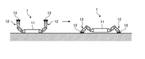
この構成によれば、胴体ユニットの正面側が上方側となる仰向けの状態で転倒しても、胴体ユニット及び複数の肢体ユニットの正面側と背面側とを切り替えることができる。このため、正面側と背面側とを切り替えることにより、胴体ユニットの正面側が下方側となるうつ伏せの状態から、転倒前の状態に復帰することができる。よって、複数種の異なる移動形態で移動する場合であっても、正面側と背面側とを切り替えることにより、復帰動作等をスムーズに行うことができるため、移動を好適に行うことができる。 According to this configuration, the front side and the back side of the trunk unit and the plurality of limb units can be switched even if the body unit falls over in a supine state where the front side is the upper side. For this reason, by switching between the front side and the back side, it is possible to return from the prone state where the front side of the body unit is the lower side to the state before the fall. Therefore, even when moving in a plurality of different types of movement, the return operation and the like can be performed smoothly by switching between the front side and the back side, so that the movement can be performed suitably.
また、前記胴体ユニット及び前記複数の肢体ユニットは、前記胴体ユニットの前記長さ方向の中央を挟んで、前記上面側の移動動作と前記下面側の移動動作とが対称な動作となるように、前記上面側と前記下面側とを切り替えて移動可能となっていることが好ましい。 Further, the trunk unit and the plurality of limb units are arranged such that the movement operation on the upper surface side and the movement operation on the lower surface side are symmetrical with respect to the center of the length direction of the trunk unit. It is preferable that the upper surface side and the lower surface side can be switched and moved.
この構成によれば、移動形態によって上面側または下面側に移動する場合であっても、胴体ユニット及び複数の肢体ユニットの上面側と下面側とを切り替えることにより、上面側への移動と、下面側への移動とを切り替えることができるため、移動を好適に行うことが可能となる。 According to this configuration, even when moving to the upper surface side or the lower surface side depending on the movement form, by switching between the upper surface side and the lower surface side of the trunk unit and the plurality of limb body units, Since the movement to the side can be switched, the movement can be suitably performed.
また、複数の前記肢体ユニットは、前記胴体ユニットの前記左側面及び前記右側面に対して、少なくとも2つの前記肢体ユニットがそれぞれ取り付けられ、前記胴体ユニットの前記長さ方向を軸方向として回転する方向をロール方向とし、前記胴体ユニットの前記幅方向を軸方向として回転する方向をピッチ方向とし、前記胴体ユニットの前記厚さ方向を軸方向として回転する方向をヨー方向とすると、前記肢体ユニットは、前記胴体ユニットの前記厚さ方向に伸ばした状態において、基端側に設けられる少なくとも2つの前記駆動軸が、前記ロール方向の前記駆動軸及び前記ピッチ方向の前記駆動軸であることが好ましい。 The plurality of limb units are attached to at least two limb units with respect to the left side surface and the right side surface of the torso unit, and rotate in the length direction of the torso unit as an axial direction. Is the roll direction, the direction of rotation with the width direction of the body unit as the axial direction is the pitch direction, and the direction of rotation with the thickness direction of the body unit as the axis direction is the yaw direction, the limb body unit is: In the state where the body unit is extended in the thickness direction, it is preferable that at least two of the drive shafts provided on the base end side are the drive shaft in the roll direction and the drive shaft in the pitch direction.
この構成によれば、胴体ユニットに対して、肢体ユニットの基端側をロール方向及びピッチ方向に作動させることができるため、肢体ユニットの可動範囲を広いものとすることができる。 According to this configuration, since the base end side of the limb body unit can be operated in the roll direction and the pitch direction with respect to the trunk unit, the movable range of the limb body unit can be widened.
また、前記胴体ユニットの前記長さ方向を軸方向として回転する方向をロール方向とし、前記胴体ユニットの前記幅方向を軸方向として回転する方向をピッチ方向とし、前記胴体ユニットの前記厚さ方向を軸方向として回転する方向をヨー方向とすると、前記肢体ユニットは、前記胴体ユニットの前記厚さ方向に伸ばした状態において、先端側に設けられる少なくとも2つの前記駆動軸が、前記ロール方向の前記駆動軸及び前記ピッチ方向の前記駆動軸であることが好ましい。 Further, a direction rotating with the length direction of the body unit as an axial direction is a roll direction, a direction rotating with the width direction of the body unit as an axial direction is a pitch direction, and the thickness direction of the body unit is Assuming that the direction of rotation as the axial direction is the yaw direction, in the state where the limb body unit is extended in the thickness direction of the torso unit, at least two drive shafts provided on the distal end side are the drive in the roll direction. The shaft and the drive shaft in the pitch direction are preferred.
この構成によれば、先端ツールに対して、肢体ユニットの先端側をロール方向及びピッチ方向に作動させることができる。このため、移動形態として、例えば、腹這い歩行を行う場合には、移動ロボットの高さを低くして、腹這い歩行を行うことができ、高さ方向に制限のある狭隘部を通過することができる。 According to this configuration, the distal end side of the limb body unit can be operated in the roll direction and the pitch direction with respect to the distal end tool. For this reason, as a movement form, for example, when performing a crawling walk, the height of the mobile robot can be lowered to perform a crawling walk, and it is possible to pass through a narrow portion that is restricted in the height direction. .
また、複数の前記肢体ユニットは、前記胴体ユニットの前記左側面及び前記右側面に対して、少なくとも2つの前記肢体ユニットがそれぞれ取り付けられ、前記胴体ユニットの前記長さ方向を軸方向として回転する方向をロール方向とし、前記胴体ユニットの前記幅方向を軸方向として回転する方向をピッチ方向とし、前記胴体ユニットの前記厚さ方向を軸方向として回転する方向をヨー方向とすると、前記肢体ユニットは、前記胴体ユニットの前記厚さ方向に伸ばした状態において、基端側に設けられる少なくとも2つの前記駆動軸が、前記ロール方向の前記駆動軸及び前記ピッチ方向の前記駆動軸であり、先端側に設けられる少なくとも2つの前記駆動軸が、前記ロール方向の前記駆動軸及び前記ピッチ方向の前記駆動軸であり、基端側に設けられる2つの前記駆動軸と先端側に設けられる2つの前記駆動軸との間に設けられる少なくとも3つの前記駆動軸が、2つのヨー方向の前記駆動軸及びピッチ方向の前記駆動軸であることが好ましい。 The plurality of limb units are attached to at least two limb units with respect to the left side surface and the right side surface of the torso unit, and rotate in the length direction of the torso unit as an axial direction. Is the roll direction, the direction of rotation with the width direction of the body unit as the axial direction is the pitch direction, and the direction of rotation with the thickness direction of the body unit as the axis direction is the yaw direction, the limb body unit is: In the state where the body unit is extended in the thickness direction, at least two of the drive shafts provided on the proximal end side are the drive shaft in the roll direction and the drive shaft in the pitch direction, and provided on the distal end side. The at least two drive shafts are the drive shaft in the roll direction and the drive shaft in the pitch direction, At least three of the drive shafts provided between the two drive shafts provided and the two drive shafts provided on the front end side are the two drive shafts in the yaw direction and the drive shaft in the pitch direction. Is preferred.
この構成によれば、胴体ユニットに対して、肢体ユニットの基端側をロール方向及びピッチ方向に作動させることができるため、肢体ユニットの可動範囲を広いものとすることができる。先端ツールに対して、肢体ユニットの先端側をロール方向及びピッチ方向に作動させることができる。このため、移動形態として、例えば、腹這い歩行を行う場合には、移動ロボットの高さを低くして、腹這い歩行を行うことができ、移動時の安定性を高めることができる。また、移動環境が不整地であっても、肢体ユニットの基端部に対して先端側をヨー方向に作動させることで、先端ツールを不整地へ好適に接地させることができるため、移動時の安定性を高めることができる。なお、ヨー方向の駆動軸は、1つが冗長軸となっている。 According to this configuration, since the base end side of the limb body unit can be operated in the roll direction and the pitch direction with respect to the trunk unit, the movable range of the limb body unit can be widened. The distal end side of the limb body unit can be operated in the roll direction and the pitch direction with respect to the distal end tool. For this reason, for example, when performing a crawling walk, the height of the mobile robot can be reduced to perform a crawling walk, and stability during movement can be increased. In addition, even if the moving environment is rough terrain, the tip tool can be suitably grounded to the rough terrain by operating the tip side in the yaw direction with respect to the base end of the limb unit. Stability can be increased. One drive axis in the yaw direction is a redundant axis.
また、前記胴体ユニットの前記長さ方向を軸方向として回転する方向をロール方向とし、前記胴体ユニットの前記幅方向を軸方向として回転する方向をピッチ方向とし、前記胴体ユニットの前記厚さ方向を軸方向として回転する方向をヨー方向とすると、前記胴体ユニットは、前記ピッチ方向の駆動軸と、前記ロール方向の駆動軸との少なくとも一方を有することが好ましい。 Further, a direction rotating with the length direction of the body unit as an axial direction is a roll direction, a direction rotating with the width direction of the body unit as an axial direction is a pitch direction, and the thickness direction of the body unit is When the direction of rotation as the axial direction is the yaw direction, the body unit preferably has at least one of the drive shaft in the pitch direction and the drive shaft in the roll direction.
この構成によれば、ピッチ方向の駆動軸により、胴体ユニットを前屈させたり、仰け反らせたりすることができる。また、ロール方向の駆動軸により、胴体ユニットを捻ることができる。このため、移動形態として、例えば、はしごを昇降する場合、はしごに対して胴体ユニットを前屈させることができるため、肢体ユニットの基端部を、はしご側に近づけることができる。よって、はしごからの胴体ユニットの距離を短くした状態で、はしごを昇降でき、はしごに保護柵が設けられる場合であっても、好適にはしごを昇降することができる。また、例えば、ピッチ方向の駆動軸及びロール方向の駆動軸を用いると、胴体ユニットを仰け反らせた状態で、胴体ユニットを捻ることができるため、肢体ユニットの基端部を高く上げることが可能となる。 According to this configuration, the body unit can be bent forward or backed by the drive shaft in the pitch direction. Further, the body unit can be twisted by the drive shaft in the roll direction. For this reason, as a moving form, for example, when raising and lowering the ladder, the trunk unit can be bent forward with respect to the ladder, so that the base end portion of the limb body unit can be brought closer to the ladder side. Therefore, the ladder can be raised and lowered in a state in which the distance of the trunk unit from the ladder is shortened, and the ladder can be preferably raised and lowered even when a protective fence is provided on the ladder. In addition, for example, when the driving shaft in the pitch direction and the driving shaft in the roll direction are used, the trunk unit can be twisted while the trunk unit is turned up, so that the base end portion of the limb body unit can be raised higher. It becomes.
また、前記胴体ユニットは、前記正面側及び前記背面側にそれぞれ設けられる車輪を有することが好ましい。 Moreover, it is preferable that the said fuselage unit has a wheel each provided in the said front side and the said back side.
この構成によれば、胴体ユニットを地面に近づけることで、車輪を地面に接地させることができるため、胴体ユニットが地面に接触することを抑制でき、また、車輪が転動することで、胴体ユニットの移動をスムーズなものとすることができる。 According to this configuration, the wheel unit can be brought into contact with the ground by bringing the fuselage unit closer to the ground, so that the fuselage unit can be prevented from coming into contact with the ground. Can be moved smoothly.
また、前記肢体ユニットは、1以上の前記駆動軸を含む関節モジュールを複数連結して構成されることが好ましい。 The limb body unit is preferably configured by connecting a plurality of joint modules including one or more drive shafts.
この構成によれば、複数の関節モジュールを連結することで、肢体ユニットを簡単に組み立てることができる。また、関節モジュール毎に交換することができるため、肢体ユニットの故障時における交換作業を容易なものとすることができる。 According to this configuration, the limb body unit can be easily assembled by connecting a plurality of joint modules. Moreover, since it can replace | exchange for every joint module, the replacement | exchange operation | work at the time of failure of a limb body unit can be made easy.
また、前記肢体ユニットの複数の前記関節モジュールは、異なる種類となる一方で、複数の前記関節モジュールに設けられる複数の前記駆動軸は、同一となっていることが好ましい。 Moreover, while the said joint module of the said limb body unit becomes a different kind, it is preferable that the said several drive shaft provided in the said several joint module is the same.
この構成によれば、複数の異なる種類の関節モジュールであっても、同一の駆動軸を用いることができるため、部品の共通化を図ることができる。 According to this configuration, even in a plurality of different types of joint modules, the same drive shaft can be used, so that parts can be shared.
また、前記肢体ユニットは、複数の前記駆動軸のうち、所定の前記駆動軸である第1駆動軸と、複数の前記駆動軸のうち、前記第1駆動軸に対して所定の角度分だけ傾斜させた第2駆動軸と、内側に前記第2駆動軸を保持すると共に、外側に前記第1駆動軸が取り付けられる保持フレームと、を有し、前記保持フレームは、前記保持フレームの外面に対して内側に窪んで形成される窪み部を有し、前記第1駆動軸は、一部が前記窪み部に収容されて、前記保持フレームに取り付けられることが好ましい。 Further, the limb body unit is inclined by a predetermined angle with respect to the first drive shaft among the plurality of drive shafts and the first drive shaft that is the predetermined drive shaft and the plurality of drive shafts. A second driving shaft that is held inside, and a holding frame that holds the second driving shaft on the inner side and is attached to the first driving shaft on the outer side, and the holding frame is arranged with respect to an outer surface of the holding frame. It is preferable that the first drive shaft is partly housed in the recess and attached to the holding frame.
この構成によれば、第1駆動軸の一部を窪み部に収容できる分、第1駆動軸の軸方向における長さを短くすることができるため、コンパクト化を図ることができる。 According to this configuration, since the length of the first drive shaft in the axial direction can be shortened by the amount that can accommodate a part of the first drive shaft in the recessed portion, it is possible to achieve compactness.
また、前記先端ツールは、前記肢体ユニットに着脱可能となっていることが好ましい。 The tip tool is preferably detachable from the limb body unit.
この構成によれば、異なる種類の先端ツールを付け替えることが可能となる。 According to this configuration, it is possible to replace different types of tip tools.
また、前記先端ツールは、地面に接する部位が平坦面に形成され、前記平坦面には、水平方向に伸びる棒状部材に係止可能な係止溝と、前記棒状部材に引っ掛けることが可能な鈎溝と、が並んで形成されていることが好ましい。 In addition, the tip tool has a flat surface formed in contact with the ground, and the flat surface has a locking groove that can be locked to a bar-like member extending in a horizontal direction, and a hook that can be hooked on the bar-like member. It is preferable that the grooves are formed side by side.
この構成によれば、移動形態として、二足歩行または四足歩行を行う場合には、平坦面を地面に接地させることができるため、移動時の安定性を高めることができる。また、移動形態として、はしごを昇降する場合には、下方側の2つの肢体ユニットに取り付けられる先端ツールの係止溝に、はしごの踏桟を係止することができ、上方側の2つの肢体ユニットに取り付けられる先端ツールの鈎溝に、はしごの踏桟または支柱を引っ掛けることができる。このため、はしごの昇降を好適に行うことができる。 According to this configuration, when performing bipedal walking or quadrupedal walking as a moving form, the flat surface can be grounded to the ground, so that stability during movement can be improved. In addition, when moving the ladder up and down as a moving form, the ladder pedestal can be locked in the locking groove of the tip tool attached to the two lower limb units, and the upper two limbs You can hook ladder ladders or struts into the troughs of the tip tool attached to the unit. For this reason, a ladder can be raised / lowered suitably.
また、前記先端ツールは、地面に接する部位が平坦面に形成され、前記平坦面とは反対側の部位には、対象物を把持可能な把持部が設けられていることが好ましい。 In addition, it is preferable that the tip tool has a flat surface at a portion in contact with the ground, and a grip portion capable of gripping an object is provided at a portion opposite to the flat surface.
この構成によれば、移動形態として、二足歩行または四足歩行を行う場合には、平坦面を地面に接地させることができるため、移動時の安定性を高めることができる。また、把持部により対象物を把持することができるため、把持部による作業を行うことが可能となる。 According to this configuration, when performing bipedal walking or quadrupedal walking as a moving form, the flat surface can be grounded to the ground, so that stability during movement can be improved. In addition, since the object can be gripped by the grip portion, the work by the grip portion can be performed.
また、前記先端ツールは、地面に接する部位が平坦面に形成され、前記平坦面とは反対側の部位が前記肢体ユニットに接続され、前記平坦面には、棒状部材に係止可能な係止溝と、前記棒状部材に引っ掛けることが可能な鈎溝と、が平行に形成され、前記平坦面内における前記鈎溝側の部位は、空間を挟んで2つに分岐して形成され、前記空間には、対象物を把持可能な把持部が収容可能に設けられていることが好ましい。 In addition, the tip tool has a flat surface at a portion in contact with the ground, a portion opposite to the flat surface is connected to the limb body unit, and the flat surface can be locked to a rod-shaped member. A groove and a ridge groove that can be hooked on the rod-shaped member are formed in parallel, and the portion on the ridge groove side in the flat surface is formed by branching into two across the space, and the space It is preferable that a gripping portion capable of gripping an object is provided so as to be accommodated.
この構成によれば、移動形態として、二足歩行または四足歩行を行う場合には、平坦面を地面に接地させることができるため、移動時の安定性を高めることができる。また、移動形態として、はしごを昇降する場合には、下方側の2つの肢体ユニットに取り付けられる先端ツールの係止溝に、はしごの踏桟を係止することができ、上方側の2つの肢体ユニットに取り付けられる先端ツールの鈎溝に、はしごの踏桟または支柱を引っ掛けることができる。このため、はしごの昇降を好適に行うことができる。さらに、把持部により対象物を把持することができるため、把持部による作業を行うことが可能となる。このとき、把持部は、空間に収容することができるため、把持部がはしごの昇降を阻害することを抑制することができる。 According to this configuration, when performing bipedal walking or quadrupedal walking as a moving form, the flat surface can be grounded to the ground, so that stability during movement can be improved. In addition, when moving the ladder up and down as a moving form, the ladder pedestal can be locked in the locking groove of the tip tool attached to the two lower limb units, and the upper two limbs You can hook ladder ladders or struts into the troughs of the tip tool attached to the unit. For this reason, a ladder can be raised / lowered suitably. Furthermore, since the object can be gripped by the grip portion, it is possible to perform work by the grip portion. At this time, since the gripping part can be accommodated in the space, it is possible to suppress the gripping part from inhibiting the raising and lowering of the ladder.
また、前記先端ツールは、撮像装置を有することが好ましい。 The tip tool preferably has an imaging device.
この構成によれば、撮像装置により撮像された画像により先端ツール周りの環境を視認することができる。 According to this configuration, the environment around the tip tool can be visually recognized from the image captured by the imaging device.
また、前記先端ツールは、前記肢体ユニットに接続される接続部と、前記接続部を挟んで一方側に設けられるつま先部と、前記接続部を挟んで他方側に設けられるかかと部と、を有し、前記つま先部は、つま先立ちして移動するときに地面に接する部位が、曲面となっていることが好ましい。 Further, the tip tool has a connection part connected to the limb body unit, a toe part provided on one side across the connection part, and a heel part provided on the other side across the connection part. And it is preferable that the site | part which contact | abuts the ground when the said toe part moves standing up to a toe is a curved surface.
この構成によれば、例えば、四足歩行時において、肢体ユニットの複数の駆動軸のうち、一部の駆動軸の駆動を停止した場合であっても、先端ツールのつま先部において、曲面となる部位を地面に確実に接地させることができる。このため、一部の駆動軸の駆動を停止できる分、電力消費を抑制することができる。 According to this configuration, for example, even when the driving of some of the drive shafts of the limb body unit is stopped during quadrupedal walking, the toe portion of the tip tool has a curved surface. The part can be reliably grounded to the ground. For this reason, power consumption can be suppressed to the extent that driving of some of the drive shafts can be stopped.
本発明の先端ツールは、胴体ユニットと、基端側が胴体ユニットに接続される複数の肢体ユニットと、を備える複数種の異なる移動形態を有する移動ロボットに取り付けられる先端ツールであって、地面に接する部位は、平坦面に形成されており、前記平坦面には、水平方向に伸びる棒状部材に係止可能な係止溝と、前記棒状部材に引っ掛けることが可能な鈎溝と、が並んで形成されていることを特徴とする。 A tip tool of the present invention is a tip tool that is attached to a mobile robot having a plurality of different movement forms including a torso unit and a plurality of limb units that are connected to the torso unit on the base end side, and is in contact with the ground The part is formed on a flat surface, and on the flat surface, a locking groove that can be locked to a bar-like member extending in the horizontal direction and a ridge groove that can be hooked on the bar-like member are formed side by side. It is characterized by being.
この構成によれば、移動形態として、二足歩行または四足歩行を行う場合には、平坦面を地面に接地させることができるため、移動時の安定性を高めることができる。また、移動形態として、はしごを昇降する場合には、下方側の2つの肢体ユニットに取り付けられる先端ツールの係止溝に、はしごの踏桟を係止することができ、上方側の2つの肢体ユニットに取り付けられる先端ツールの鈎溝に、はしごの踏桟または支柱を引っ掛けることができる。このため、はしごの昇降を好適に行うことができる。 According to this configuration, when performing bipedal walking or quadrupedal walking as a moving form, the flat surface can be grounded to the ground, so that stability during movement can be improved. In addition, when moving the ladder up and down as a moving form, the ladder pedestal can be locked in the locking groove of the tip tool attached to the two lower limb units, and the upper two limbs You can hook ladder ladders or struts into the troughs of the tip tool attached to the unit. For this reason, a ladder can be raised / lowered suitably.
本発明の他の先端ツールは、胴体ユニットと、基端側が胴体ユニットに接続される複数の肢体ユニットと、を備える複数種の異なる移動形態を有する移動ロボットに取り付けられる先端ツールであって、地面に接する部位は、平坦面に形成されており、前記平坦面とは反対側の部位には、対象物を把持可能な把持部が設けられていることを特徴とする。 Another tip tool of the present invention is a tip tool to be attached to a mobile robot having a plurality of different movement forms including a torso unit and a plurality of limb units whose base end side is connected to the torso unit, The part in contact with is formed on a flat surface, and a grip part capable of gripping an object is provided on a part opposite to the flat surface.
この構成によれば、移動形態として、二足歩行または四足歩行を行う場合には、平坦面を地面に接地させることができるため、移動時の安定性を高めることができる。また、把持部により対象物を把持することができるため、把持部による作業を行うことが可能となる。 According to this configuration, when performing bipedal walking or quadrupedal walking as a moving form, the flat surface can be grounded to the ground, so that stability during movement can be improved. In addition, since the object can be gripped by the grip portion, the work by the grip portion can be performed.
本発明の他の先端ツールは、胴体ユニットと、基端側が胴体ユニットに接続される複数の肢体ユニットと、を備える複数種の異なる移動形態を有する移動ロボットに取り付けられる先端ツールであって、地面に接する部位は、平坦面に形成され、前記平坦面とは反対側の部位は、前記肢体ユニットに接続され、前記平坦面には、棒状部材に係止可能な係止溝と、前記棒状部材に引っ掛けることが可能な鈎溝と、が平行に形成され、前記平坦面内における前記鈎溝側の部位は、空間を挟んで2つに分岐して形成され、前記空間には、対象物を把持可能な把持部が収容可能に設けられていることを特徴とする。 Another tip tool of the present invention is a tip tool to be attached to a mobile robot having a plurality of different movement forms including a torso unit and a plurality of limb units whose base end side is connected to the torso unit, The part in contact with is formed on a flat surface, the part opposite to the flat surface is connected to the limb body unit, the flat surface has a locking groove that can be locked to a bar-shaped member, and the bar-shaped member And the groove-side portion in the flat surface is formed by branching into two with a space in between, and an object is placed in the space. A gripping portion capable of being gripped is provided so as to be accommodated.
この構成によれば、移動形態として、二足歩行または四足歩行を行う場合には、平坦面を地面に接地させることができるため、移動時の安定性を高めることができる。また、移動形態として、はしごを昇降する場合には、下方側の2つの肢体ユニットに取り付けられる先端ツールの係止溝に、はしごの踏桟を係止することができ、上方側の2つの肢体ユニットに取り付けられる先端ツールの鈎溝に、はしごの踏桟または支柱を引っ掛けることができる。このため、はしごの昇降を好適に行うことができる。さらに、把持部により対象物を把持することができるため、把持部による作業を行うことが可能となる。このとき、把持部は、空間に収容することができるため、把持部がはしごの昇降を阻害することを抑制することができる。 According to this configuration, when performing bipedal walking or quadrupedal walking as a moving form, the flat surface can be grounded to the ground, so that stability during movement can be improved. In addition, when moving the ladder up and down as a moving form, the ladder pedestal can be locked in the locking groove of the tip tool attached to the two lower limb units, and the upper two limbs You can hook ladder ladders or struts into the troughs of the tip tool attached to the unit. For this reason, a ladder can be raised / lowered suitably. Furthermore, since the object can be gripped by the grip portion, it is possible to perform work by the grip portion. At this time, since the gripping part can be accommodated in the space, it is possible to suppress the gripping part from inhibiting the raising and lowering of the ladder.
また、撮像装置が設けられることが好ましい。 An imaging device is preferably provided.
この構成によれば、撮像装置により撮像された画像により先端ツール周りの環境を視認することができる。 According to this configuration, the environment around the tip tool can be visually recognized from the image captured by the imaging device.
また、前記肢体ユニットに接続される接続部と、前記接続部を挟んで一方側に設けられるつま先部と、前記接続部を挟んで他方側に設けられるかかと部と、を有し、前記つま先部は、つま先立ちして移動するときに地面に接する部位が、曲面となっていることが好ましい。 The toe unit includes a connection part connected to the limb unit, a toe part provided on one side across the connection part, and a heel part provided on the other side across the connection part. It is preferable that the part which contacts the ground when moving while standing on the tiptoe is a curved surface.
この構成によれば、例えば、四足歩行時において、肢体ユニットの複数の駆動軸のうち、一部の駆動軸の駆動を停止した場合であっても、先端ツールのつま先部において、曲面となる部位を地面に確実に接地させることができる。このため、一部の駆動軸の駆動を停止できる分、電力消費を抑制することができる。 According to this configuration, for example, even when the driving of some of the drive shafts of the limb body unit is stopped during quadrupedal walking, the toe portion of the tip tool has a curved surface. The part can be reliably grounded to the ground. For this reason, power consumption can be suppressed to the extent that driving of some of the drive shafts can be stopped.
以下に、本発明に係る実施形態を図面に基づいて詳細に説明する。なお、この実施形態によりこの発明が限定されるものではない。また、下記実施形態における構成要素には、当業者が置換可能かつ容易なもの、あるいは実質的に同一のものが含まれる。さらに、以下に記載した構成要素は適宜組み合わせることが可能であり、また、実施形態が複数ある場合には、各実施形態を組み合わせることも可能である。 Embodiments according to the present invention will be described below in detail with reference to the drawings. In addition, this invention is not limited by this embodiment. In addition, constituent elements in the following embodiments include those that can be easily replaced by those skilled in the art or those that are substantially the same. Furthermore, the constituent elements described below can be appropriately combined, and when there are a plurality of embodiments, the embodiments can be combined.
[実施形態1]
図1は、実施形態1に係る移動ロボットの外観斜視図である。図2は、実施形態1の移動ロボットに設けられる駆動軸の構成図である。図3は、実施形態1の移動ロボットに取り付けられる先端ツールの一例を示す外観斜視図である。図4は、実施形態1の移動ロボットに取り付けられる先端ツールの一例を示す外観斜視図である。
[Embodiment 1]
FIG. 1 is an external perspective view of the mobile robot according to the first embodiment. FIG. 2 is a configuration diagram of a drive shaft provided in the mobile robot according to the first embodiment. FIG. 3 is an external perspective view illustrating an example of a tip tool attached to the mobile robot according to the first embodiment. FIG. 4 is an external perspective view showing an example of a tip tool attached to the mobile robot according to the first embodiment.
図1に示す移動ロボット1は、複数種の異なる移動形態を有するロボットであり、移動形態としては、例えば、二足歩行、三足歩行、四足歩行、はしご昇降及び腹這い歩行等が実行可能となっている。この移動ロボット1は、移動環境に応じた移動形態で、予め指定された移動先に移動する。 The mobile robot 1 shown in FIG. 1 is a robot having a plurality of different movement forms, and as the movement form, for example, biped walking, tripod walking, quadruped walking, ladder raising / lowering and crawling walking can be executed. It has become. The mobile robot 1 moves to a movement destination designated in advance in a movement form corresponding to the movement environment.
図1に示すように、移動ロボット1は、胴体ユニット11と、4つの肢体ユニット12と、4つの先端ツール13とを備えている。
As shown in FIG. 1, the mobile robot 1 includes a
胴体ユニット11は、正面、背面、上面、下面、左側面及び右側面を有する略長方体形状に形成されている。ここで、胴体ユニット11の正面及び背面が対向する方向を厚さ方向とする。また、厚さ方向に直交すると共に胴体ユニット11の上面及び下面が対向する方向を長さ方向とする。さらに、厚さ方向及び長さ方向に直交する方向を幅方向とする。この胴体ユニット11は、長さ方向において並べて設けられる2つの胴体フレーム21と、2つの胴体フレーム21の間に設けられる2つの胴体側駆動軸22と、を有している。
The
各胴体フレーム21は、左側面及び右側面にそれぞれ1つの肢体ユニット12が接続されている。また、各胴体フレーム21は、ほぼ同一の構成となっている。
Each
図2に示す2つの胴体側駆動軸22は、ピッチ軸22pと、ロール軸22rからなる。この2つの胴体側駆動軸22は、同一の構成となっている。ここで、ロール軸22rは、胴体ユニット11の長さ方向周りに回転する。また、ピッチ軸22pは、胴体ユニット11の幅方向周りに回転する。さらに、後述する、ヨー軸は、胴体ユニット11の厚さ方向周りに回転する。
The two body
ピッチ軸22pは、胴体ユニット11を折り曲げるように駆動する。具体的に、ピッチ軸22pは、2つの胴体フレーム21のうち、一方の胴体フレーム21の長さ方向と、他方の胴体フレーム21の長さ方向とが、所定の角度をなすように回転駆動する。ここで、ピッチ軸22pは、例えば、180°回転可能に構成されている。このため、胴体ユニット11は、正面側に前屈する角度が90°となる。つまり、一方の胴体フレーム21の長さ方向と、他方の胴体フレーム21の長さ方向とが、正面側において90°となるように回転駆動する。また、胴体ユニット11は、背面側に仰け反る角度が90°となる。つまり、一方の胴体フレーム21の長さ方向と、他方の胴体フレーム21の長さ方向とが、背面側において90°となるように回転駆動する。
The
ロール軸22rは、胴体ユニット11を捻るように駆動する。具体的に、ロール軸22rは、2つの胴体フレーム21のうち、一方の胴体フレーム21の幅方向と、他方の胴体フレーム21の幅方向とが、所定の角度をなすように回転駆動する。ここで、ロール軸22rは、ピッチ軸22pと同様に、例えば、180°回転可能に構成されている。このため、胴体ユニット11は、長さ方向に直交する面内において、一方の胴体フレーム21に対する他方の胴体フレーム21の捻れ角度が±90°となる。つまり、一方の胴体フレーム21の幅方向と、他方の胴体フレーム21の幅方向とが、±90°となるように回転駆動する。
The
なお、実施形態1では、2つの胴体フレーム21の間に設けられる胴体側駆動軸22を2つ設けたが、この構成に特に限定されず、移動ロボット1が用いられる移動環境に応じて適宜設けてもよい。
In the first embodiment, two body-
4つの肢体ユニット12は、胴体ユニット11の左側面及び右側面に対して、2つの肢体ユニット12がそれぞれ取り付けられている。具体的には、上記のように、2つの肢体ユニット12が、一方の胴体フレーム21の左側面及び右側面に接続され、残りの2つの肢体ユニット12が、他方の胴体フレーム21の左側面及び右側面に接続されている。この4つの肢体ユニット12は、同一の構成となっている。次に、各肢体ユニット12について説明する。なお、4つの肢体ユニット12は、同一の構成となっていることから、下記の説明では、1つの肢体ユニット12について説明し、残りの3つの肢体ユニット12については説明を省略する。また、実施形態1では、4つの肢体ユニット12を用いたが、複数の肢体ユニット12であればよく、個数は特に限定されない。
The four
肢体ユニット12は、その基端部が胴体ユニット11に取り付けられ、その先端部に先端ツール13が取り付けられている。このため、肢体ユニット12は、その先端側が地面に接地する側となっている。この肢体ユニット12は、複数種の異なる関節モジュール31を有し、複数種の異なる関節モジュール31を連結して構成されている。また、肢体ユニット12は、複数の肢体側駆動軸32を有しており、各関節モジュール31に1以上の肢体側駆動軸32が配置されている。
The
複数種の関節モジュール31は、肢体ユニット12の基端側から順に、基端関節モジュール35と、中間関節モジュール36と、先端関節モジュール37と、を有している。
The plural types of
基端関節モジュール35は、2つの肢体側駆動軸32と、2つの肢体側駆動軸32を保持する保持フレーム41とを有している。2つの肢体側駆動軸32は、肢体ユニット12の基端側から順に、ピッチ軸32pと、ロール軸32rとを有している。ここで、ピッチ軸32pのピッチ方向、ロール軸32rのロール方向及び後述するヨー軸32yのヨー方向とは、肢体ユニット12を、胴体ユニット11の厚さ方向に沿って伸ばした時に規定される方向である。
The proximal
ピッチ軸32pは、胴体ユニット11に対して肢体ユニット12を回転するように駆動する。つまり、ピッチ軸32pは、胴体ユニット11の左側面及び右側面の面内において、幅方向を軸方向として、肢体ユニット12を回転駆動する。
The
ロール軸32rは、肢体ユニット12の基端部に対して肢体ユニット12先端部を回転するように駆動する。つまり、ロール軸32rは、胴体ユニット11の上面及び下面の面内において、長さ方向を軸方向として、先端側の肢体ユニット12の一部を回転駆動する。
The
図1に示す中間関節モジュール36は、3つの肢体側駆動軸32と、それらを保持する保持フレーム42とを有している。3つの肢体側駆動軸32は、図2に示すように肢体ユニット12の基端側から順に、ヨー軸32yと、ピッチ軸32pと、ヨー軸32yからなる。
The intermediate
中間関節モジュール36のヨー軸32yは、肢体ユニット12が伸びる方向を軸方向として、肢体ユニット12の基端部に対して肢体ユニット12の先端部を回転させる。なお、2つのヨー軸32yは、1つが冗長軸となっている。
The
中間関節モジュール36のピッチ軸32pは、肢体ユニット12が伸びる方向において、肢体ユニット12の基端部に対して肢体ユニット12の先端部を折り曲げるように回転させる。
The
先端関節モジュール37は、2つの肢体側駆動軸32と、それらを保持する保持フレーム43とを有している。2つの肢体側駆動軸32は、肢体ユニット12の基端側から順に、ピッチ軸32pと、ロール軸32rとを有している。なお、先端関節モジュール37については、基端関節モジュール35と同様の構成であるため、説明を省略する。
The distal
このように構成される肢体ユニット12は、計7つの肢体側駆動軸32を有していることから、7自由度となっている。つまり、肢体ユニット12は、基端部側から順に、ピッチ方向、ロール方向、ヨー方向、ピッチ方向、ヨー方向、ピッチ方向、ロール方向の肢体側駆動軸32となっている。なお、実施形態1では、7自由度としたが、少なくとも7自由度であればよく、7自由度以上であってもよい。
The
4つの先端ツール13は、4つの肢体ユニット12に対して、着脱自在となっており、使用環境に応じて複数種用意されている。4つの先端ツール13は、同一の構成となっていることから、下記の説明では、1つの先端ツール13について説明し、残りの3つの先端ツール13については説明を省略する。この先端ツール13は、エンドエフェクタとも呼称されている。なお、図3では、複数種の先端ツール13のうち、一種の先端ツール13aを説明し、図4では、複数種の先端ツール13のうち、他の一種の先端ツール13bを説明する。
The four
図3に示す先端ツール13aは、主として、移動ロボット1が二足歩行または四足歩行を行うと共に、はしごを昇降する際に用いられる。先端ツール13aは、肢体ユニット12に着脱自在に取り付けられる接続部51と、接続部51を挟んで一方側に設けられるつま先部52と、接続部51を挟んで他方側に設けられるかかと部53と、を有する。先端ツール13aは、肢体ユニット12への取付側とは反対側の部位が、地面に接する部位となっており、地面に接する部位には、平坦面P1が形成されている。
The
この平坦面P1には、はしごの踏桟に係止可能な係止溝54と、はしごの踏桟または支柱(棒状部材)に引っ掛けることが可能な鈎溝55とが形成されている。係止溝54は、平坦面P1において、つま先部52とかかと部53とをつなぐ方向とは直交する方向に、延在して形成されている。この係止溝54は、つま先部52とかかと部53とをつなぐ方向に並べて2本形成され、2本の係止溝54は、平行に形成されている。なお、2本の係止溝54のうち、1本の係止溝54は、接続部51の位置に形成され、他の1本の係止溝54は、かかと部53の位置に形成される。鈎溝55は、平坦面P1において、つま先部52とかかと部53とをつなぐ方向とは直交する方向に、延在して形成されている。つまり、鈎溝55は、2本の係止溝54と平行に形成されている。この鈎溝55は、つま先部52の位置に形成される。なお、実施形態1において、鈎溝55は、つま先部52の平坦面P1(下面)に形成したが、鈎溝55は、かかと部53の上面に設けることも可能である。
The flat surface P <b> 1 is formed with a locking
図4に示す先端ツール13bは、主として、移動ロボット1が二足歩行または四足歩行を行うと共に、各種作業を行う際に用いられる。先端ツール13bは、肢体ユニット12に着脱自在に取り付けられる接続部61と、接続部61を挟んで一方側に設けられるつま先部62と、接続部61を挟んで他方側に設けられるかかと部63と、を有する。先端ツール13bは、肢体ユニット12への取付側とは反対側の部位が、地面に接する部位となっており、地面に接する部位には、平坦面P2が形成されている。
The
また、先端ツール13bは、平坦面P2とは反対側のつま先部62に、対象物を把持可能な把持部64が設けられている。把持部64は、複数本の指を含んで構成され、複数本の指は、作業時において展開される一方で、歩行時において折り畳まれる。
Further, the
このように構成される移動ロボット1、より具体的には、胴体ユニット11及び4つの肢体ユニット12は、厚さ方向の中央を挟んで、正面側の移動動作と背面側の移動動作とが対称の移動動作を実行可能な構成となっている。また、胴体ユニット11及び4つの肢体ユニット12は、長さ方向の中央を挟んで、上面側の移動動作と下面側の移動動作とが対称の移動動作を実行可能な構成となっている。さらに、胴体ユニット11及び4つの肢体ユニット12は、幅方向の中央を挟んで、左側面側の移動動作と右側面側の移動動作とが対称の移動動作を実行可能な構成となっている。
In the mobile robot 1 configured as described above, more specifically, the
そして、移動ロボット1は、図示しない制御装置によって移動制御される。具体的に、制御装置は、移動ロボット1に設けられる上記の各種駆動軸22,32の回転駆動を制御することで、移動制御を実行している。ここで、移動ロボット1の移動制御は、自律移動制御としてもよいし、オペレータによる遠隔操作により移動制御してもよいし、これらを組み合わせて移動制御してもよい。実施形態1において、移動ロボット1の移動制御は、オペレータが移動環境を把握し、把握した移動環境に応じて、オペレータが移動ロボット1の移動形態を選択すると共に、移動先を指定する。この後、移動ロボット1は、選択された移動形態と、指定された移動先とに基づいて、移動を行う。
The mobile robot 1 is controlled to move by a control device (not shown). Specifically, the control device executes the movement control by controlling the rotational drive of the
ここで、移動制御される移動ロボット1は、図5から図10に示すように、複数種の異なる移動形態に応じた複数の移動モードを有している。図5は、実施形態1の移動ロボットの二足歩行モードを示す説明図である。図6は、実施形態1の移動ロボットの四足歩行モードを示す説明図である。図7は、実施形態1の移動ロボットの腹這い歩行モードを示す説明図である。図8は、実施形態1の移動ロボットのはしご昇降モードの一例を示す説明図である。図9は、実施形態1の移動ロボットのはしご昇降モードの一例を示す説明図である。図10は、実施形態1の移動ロボットの三足歩行モードの一例を示す説明図である。複数の移動モードとしては、二足歩行モード、三足歩行モード、四足歩行モード、はしご昇降モード、及び腹這い歩行モードを有している。 Here, the mobile robot 1 subject to movement control has a plurality of movement modes corresponding to a plurality of different movement forms, as shown in FIGS. FIG. 5 is an explanatory diagram illustrating a biped walking mode of the mobile robot according to the first embodiment. FIG. 6 is an explanatory diagram illustrating a quadruped walking mode of the mobile robot according to the first embodiment. FIG. 7 is an explanatory diagram illustrating a hungry walking mode of the mobile robot according to the first embodiment. FIG. 8 is an explanatory diagram illustrating an example of a ladder raising / lowering mode of the mobile robot according to the first embodiment. FIG. 9 is an explanatory diagram illustrating an example of a ladder lifting mode of the mobile robot according to the first embodiment. FIG. 10 is an explanatory diagram illustrating an example of a tripod walking mode of the mobile robot according to the first embodiment. As a plurality of movement modes, there are a biped walking mode, a tripod walking mode, a quadruped walking mode, a ladder lifting mode, and a hungry walking mode.
図5に示すように、二足歩行モードにおいて、移動ロボット1は、胴体ユニット11の長さ方向を鉛直方向とし、下方側に位置する2つの肢体ユニット12を脚とし、上方側に位置する2つの肢体ユニット12を腕として機能させる。
As shown in FIG. 5, in the biped walking mode, the mobile robot 1 uses the length direction of the
図6に示すように、四足歩行モードにおいて、移動ロボット1は、胴体ユニット11の厚さ方向を鉛直方向とし、4つの肢体ユニット12を脚として機能させる。なお、四足歩行モードでは、胴体ユニット11の一部を、地面に接地させた状態で移動する胴体接地四足歩行モードを実行してもよい。
As shown in FIG. 6, in the quadruped walking mode, the mobile robot 1 causes the thickness direction of the
図7に示すように、腹這い歩行モードにおいて、移動ロボット1は、胴体ユニット11の厚さ方向を鉛直方向とし、4つの肢体ユニット12を脚として機能させる。ここで、4つの肢体ユニット12は、基端関節モジュール35がロール軸32r及びピッチ軸32pを有していることから、胴体ユニット11の正面及び背面の面内に沿わせた作動が実行可能となる。また、4つの肢体ユニット12は、先端関節モジュール37がロール軸32r及びピッチ軸32pを有していることから、先端ツール13の平坦面P1,P2に沿わせた作動が実行可能となる。このため、移動ロボット1は、腹這い歩行モードにおいて、鉛直方向における高さが高くなることを抑制でき、地面に這いつくばった状態で、移動することが可能となる。
As shown in FIG. 7, in the crawling walking mode, the mobile robot 1 causes the thickness direction of the
図8及び図9に示すように、はしご昇降モードにおいて、移動ロボット1は、胴体ユニット11の長さ方向を鉛直方向とし、下方側に位置する2つの肢体ユニット12を脚とし、上方側に位置する2つの肢体ユニット12を腕として機能させる。ここで、はしご71は、鉛直方向に延びる平行に配置された2本の支柱72と、2本の支柱72同士を接続する水平方向に延びる複数の踏桟73と、はしご71を使用する使用者を保護するための保護柵74とを含んで構成されている。保護柵74は円筒形状に形成されており、その内部が使用者または移動ロボット1の通路となっている。
As shown in FIGS. 8 and 9, in the ladder raising / lowering mode, the mobile robot 1 uses the length direction of the
移動ロボット1は、はしご昇降モードにおいて、先端ツール13として、図3に示す先端ツール13aを用いている。移動ロボット1は、脚として機能する2つの肢体ユニット12に取り付けられる先端ツール13aの係止溝54に、はしご71の踏桟73を係止する。また、移動ロボット1は、腕として機能する2つの肢体ユニット12に取り付けられる先端ツール13aの鈎溝55に、はしご71の踏桟73を引っ掛ける。この状態で、移動ロボット1は、脚として機能する2つの肢体ユニット12を交互に作動させて、はしご71の踏桟73を1つずつ昇降し、また、腕として機能する2つの肢体ユニット12を交互に作動させて、はしご71の踏桟73を1つずつ昇降することで、はしご71を昇降する。ここで、胴体ユニット11は、ピッチ軸22pを有していることから、胴体ユニット11のはしご71側の面を前屈させた状態で、はしご71を昇降する。胴体ユニット11を前屈させると、4つの肢体ユニット12の基端部がはしご71側に近づく。このため、移動ロボット1は、移動ロボット1全体をはしご71側に寄せることで、移動ロボット1とはしご71との間の距離Lを短くでき、保護柵74の内側に収まった状態で、はしご71を昇降することが可能となる。
The mobile robot 1 uses the
図9に示すように、移動ロボット1がはしご71を登り切る場合において、肢体ユニット12は、2つのヨー軸32yを有している。このため、移動ロボット1は、片脚及び片腕となる2つの肢体ユニット12をはしご71に固定した状態で、固定された片脚のヨー軸32yを駆動させることにより、自由となる片脚の肢体ユニット12がはしご71から離れた着地点75に接地するように、胴体ユニット11を回転することが可能となる。このように、移動ロボット1は、はしご昇降モードにおいて、はしご71の昇降だけでなく、はしご71の登り切りも行うことができる。
As shown in FIG. 9, when the mobile robot 1 climbs up the
図10に示すように、三足歩行モードにおいて、移動ロボット1は、胴体ユニット11の厚さ方向を鉛直方向とし、3つの肢体ユニット12を脚とし、残りの1つの肢体ユニット12を作業用のマニピュレータとして機能させる。このため、移動ロボット1は、脚として機能する3つの肢体ユニット12を移動制御して歩行すると共に、1つの肢体ユニット12により作業を行うことが可能となる。なお、三足歩行モードでは、胴体ユニット11の一部を、地面に接地させた状態で移動する胴体接地三足歩行モードを実行してもよい。
As shown in FIG. 10, in the three-legged walking mode, the mobile robot 1 uses the thickness direction of the
また、移動ロボット1は、図11に示すように、3つの肢体ユニット12を脚とし支持しつつ、1つの肢体ユニット12を作業用のマニピュレータとして機能させる三足支持作業モードを実行することで、高所への作業を実行している。図11は、実施形態1の移動ロボットの三足支持作業モードの一例を示す説明図である。移動ロボット1は、胴体ユニット11にピッチ軸22p及びロール軸22rが設けられている。このため、移動ロボット1は、三足支持作業モードにおいて、ピッチ軸22pを駆動することにより、胴体ユニット11を仰け反らせることができ、また、ロール軸22rを駆動することにより、胴体ユニット11を捻ることができる。このため、移動ロボット1は、マニピュレータとして機能する1つの肢体ユニット12の基端部を、鉛直方向の上方側に位置させることができるため、高所への作業を実行可能としている。
Further, as shown in FIG. 11, the mobile robot 1 supports a three
また、移動ロボット1は、図12に示すように、転倒時において元の移動モードに復帰する復帰動作モードを実行可能となっている。図12は、実施形態1の移動ロボットの復帰動作モードの一例を示す説明図である。移動ロボット1は、転倒時において、移動ロボット1の正面が上方側となる仰向け状態となった場合、正面及び背面を切り替えることで、移動ロボット1の正面が下方側となるうつ伏せの状態とすることができる。このため、うつ伏せ状態から、元の移動モードに復帰できる。例えば、元の移動モードが四足歩行モードである場合には、うつ伏せ状態から、4つの肢体ユニット12により、胴体ユニット11を鉛直方向の上方側に持ち上げることで、四足歩行モードにできるため、迅速に復帰することが可能となる。
Further, as shown in FIG. 12, the mobile robot 1 can execute a return operation mode in which the mobile robot 1 returns to the original movement mode when it falls. FIG. 12 is an explanatory diagram illustrating an example of a return operation mode of the mobile robot according to the first embodiment. When the mobile robot 1 falls, if the front of the mobile robot 1 is in a supine state where the front is on the upper side, the mobile robot 1 is in a prone state where the front of the mobile robot 1 is on the lower side by switching between the front and the back. Can do. For this reason, it can return to the original movement mode from the prone state. For example, when the original movement mode is the quadruped walking mode, it is possible to enter the quadruped walking mode by lifting the
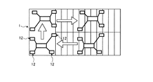
また、移動ロボット1は、正面及び背面を切り替える、または上面及び下面を切り替えることで、例えば、図13及び図14に示す移動を実行することが可能となる。図13は、実施形態1の移動ロボットの四足歩行モード時における折り返し移動の一例を示す説明図である。また、図14は、実施形態1の移動ロボットの二足歩行モード時における折り返し移動の一例を示す説明図である。 In addition, the mobile robot 1 can execute the movement shown in FIGS. 13 and 14, for example, by switching the front and back, or switching the top and bottom surfaces. FIG. 13 is an explanatory diagram illustrating an example of the folding movement in the quadruped walking mode of the mobile robot according to the first embodiment. Moreover, FIG. 14 is explanatory drawing which shows an example of the return | turnback movement in the bipedal walking mode of the mobile robot of Embodiment 1. FIG.
図13に示すように、移動ロボット1が、一方向に延びる階段から、踊り場を経て、一方向の逆方向に延びる階段を移動する場合について説明する。このとき、移動ロボット1は、階段を安定的に移動可能なように、四足歩行モードとなっている。四足歩行モードとなる移動ロボット1は、胴体ユニット11の上面側を先頭側として、一方向に階段を移動した後、踊り場に到達する。踊り場に到達した移動ロボット1は、向きを変えることなく、踊り場において、一方向に延びる階段から逆方向に延びる階段まで移動する。この後、移動ロボット1は、胴体ユニット11の上面及び下面を切り替えることで、胴体ユニット11の上面側を先頭側として、逆方向に階段を移動することが可能となる。
As shown in FIG. 13, the case where the mobile robot 1 moves from a stairway extending in one direction to a staircase extending in the opposite direction of one direction through a landing is described. At this time, the mobile robot 1 is in a quadruped walking mode so that the stairs can be moved stably. The mobile robot 1 in the quadruped walking mode moves to the landing after moving the stairs in one direction with the upper surface side of the
また、図14に示すように、移動ロボット1が、一方向に延びる階段から、踊り場を経て、一方向の逆方向に延びる階段を移動する場合について説明する。このとき、移動ロボット1は、階段を安定的に移動可能なように、四足歩行モードとなる一方で、図14の踊り場は、図13の踊り場に比して狭いことから、踊り場では二足歩行モードとなる。四足歩行モードとなる移動ロボット1は、胴体ユニット11の上面側を先頭側として、一方向に階段を移動した後、踊り場に到達する。踊り場に到達した移動ロボット1は、二足歩行モードに切り替えられる。この後、二足歩行モードとなる移動ロボット1は、向きを変えることなく、踊り場において、一方向に延びる階段から逆方向に延びる階段まで横歩きで移動する。この後、移動ロボット1は、胴体ユニット11の正面及び背面を切り替えた後、四足歩行モードに移行する。そして、移動ロボット1は、胴体ユニット11の上面側を先頭側として、逆方向に階段を移動することが可能となる。
Moreover, as shown in FIG. 14, the case where the mobile robot 1 moves from a stair extending in one direction to a stair extending in the opposite direction of one direction through a landing is described. At this time, the mobile robot 1 is in a quadruped walking mode so that the stairs can move stably, while the landing in FIG. 14 is narrower than the landing in FIG. It becomes walking mode. The mobile robot 1 in the quadruped walking mode moves to the landing after moving the stairs in one direction with the upper surface side of the
以上のように、実施形態1によれば、胴体ユニット11の正面側が上方側となる仰向けの状態で転倒しても、胴体ユニット11及び4つの肢体ユニット12の正面側と背面側とを切り替えることができる。このため、正面側と背面側とを切り替えることにより、胴体ユニット11の正面側が下方側となるうつ伏せの状態から、転倒前の状態に復帰することができる。よって、複数種の異なる移動形態で移動する場合であっても、正面側と背面側とを切り替えることにより、復帰動作等をスムーズに行うことができるため、移動を好適に行うことができる。
As described above, according to the first embodiment, the front side and the back side of the
また、実施形態1によれば、移動形態によって上面側または下面側に移動する場合であっても、胴体ユニット11及び4つの肢体ユニット12の上面側と下面側とを切り替えることにより、上面側への移動と、下面側への移動とを切り替えることができるため、移動を好適に行うことが可能となる。
In addition, according to the first embodiment, even when moving to the upper surface side or the lower surface side depending on the movement mode, the upper surface side and the lower surface side of the
また、実施形態1によれば、胴体ユニット11の左側面及び右側面に肢体ユニット12を設け、また、胴体ユニット11に対して、肢体ユニット12の基端側をロール方向及びピッチ方向に作動させることができるため、肢体ユニット12の可動範囲を広いものとすることができる。
According to the first embodiment, the
また、実施形態1によれば、先端ツール13に対して、肢体ユニット12の先端側をロール方向及びピッチ方向に作動させることができる。このため、移動形態として、例えば、腹這い歩行モードを実行する場合には、移動ロボット1の高さを低くして、腹這い歩行を行うことができ、高さ方向に制限のある狭隘部を通過することができる。
Further, according to the first embodiment, the distal end side of the
また、実施形態1によれば、移動環境が不整地であっても、肢体ユニット12の基端部に対して先端側をヨー方向に作動させることで、先端ツール13を不整地へ好適に接地させることができるため、移動時の安定性を高めることができる。また、2つのヨー軸32yのうち、1つが冗長軸となっていることから、ヨー軸32yが1つ故障しても歩行の継続が可能であり、移動時の安定性をさらに高めることができる。
Further, according to the first embodiment, even when the moving environment is rough terrain, the
また、実施形態1によれば、胴体ユニット11にピッチ軸22pを設けることで、胴体ユニット11を前屈させたり、仰け反らせたりすることができる。また、胴体ユニット11にロール軸22rを設けることで、胴体ユニット11を捻ることができる。このため、移動形態として、例えば、図8に示すはしご71を昇降する場合、はしご71に対して胴体ユニット11を前屈させることができるため、肢体ユニット12の基端部を、はしご71側に近づけることができる。よって、はしご71からの胴体ユニット11の距離を短くした状態で、はしご71を昇降でき、はしご71に保護柵74が設けられる場合であっても、好適にはしご71を昇降することができる。また、胴体ユニット11にピッチ軸22p及びロール軸22rを設けることで、図11に示す三足支持作業モードにおいて、胴体ユニット11を仰け反らせた状態で、胴体ユニット11を捻ることができるため、肢体ユニット12の基端部を高く上げることが可能となる。
Further, according to the first embodiment, the
また、実施形態1によれば、肢体ユニット12を複数の関節モジュール31を連結して構成することで、肢体ユニット12を簡単に組み立てることができる。また、関節モジュール31毎に交換することができるため、肢体ユニット12の故障時における交換作業を容易なものとすることができる。
Further, according to the first embodiment, the
また、実施形態1によれば、複数の異なる種類の関節モジュール31であっても、同一の肢体側駆動軸32を用いることができるため、部品の共通化を図ることができる。
In addition, according to the first embodiment, the same limb body
また、実施形態1によれば、先端ツール13を、肢体ユニット12に着脱可能に取り付けることで、異なる種類の先端ツール13を付け替えることが可能となる。
Further, according to the first embodiment, it is possible to replace different types of
また、実施形態1によれば、図3に示す先端ツール13aを用いることで、二足歩行または四足歩行を行う場合には、平坦面P1を地面に接地させることができるため、移動時の安定性を高めることができる。また、はしご71を昇降する場合には、下方側の2つの肢体ユニット12に取り付けられる先端ツール13aの係止溝54に、はしご71の踏桟73を係止することができ、上方側の2つの肢体ユニット12に取り付けられる先端ツール13aの鈎溝55に、はしご71の踏桟73または支柱72を引っ掛けることができる。このため、はしご71の昇降を好適に行うことができる。
Further, according to the first embodiment, by using the
また、実施形態1によれば、図4に示す先端ツール13bを用いることで、二足歩行または四足歩行を行う場合には、平坦面P2を地面に接地させることができるため、移動時の安定性を高めることができる。また、把持部64により対象物を把持することができるため、移動ロボット1は、把持部64による作業を行うことが可能となる。
Further, according to the first embodiment, by using the
[実施形態2]
次に、図15を参照して、実施形態2に係る移動ロボット101について説明する。図15は、実施形態2の移動ロボットの側面図である。なお、実施形態2では、重複した記載を避けるべく、実施形態1と異なる部分について説明し、実施形態1と同様の構成である部分については、同じ符号を付して説明する。
[Embodiment 2]
Next, the
実施形態2の移動ロボット101は、その胴体ユニット11の左側面及び右側面に、複数の車輪102が取り付けられている。具体的に、複数の車輪102は、左側面及び右側面に4つずつ配置される。各側面に設置される4つの車輪102のうち、2つの車輪102は、正面側に配置され、残りの2つの車輪102は、背面側に配置される。そして、8つの車輪102は、胴体ユニット11の厚さ方向、長さ方向及び幅方向における位置が対称となるように配置される。各車輪102は、幅方向を軸方向として回転可能となっており、正面側の4つの車輪102は、胴体ユニット11の正面から突出するように配置され、同様に、背面側の4つの車輪102は、胴体ユニット11の背面から突出するように配置されている。
The
以上のように、実施形態2によれば、胴体ユニット11を地面に近づけて、車輪102を地面に接地させることで、胴体ユニット11で自重を支持することができることから、肢体ユニット11に加わる負荷を軽減することができ、また、車輪102が転動することで、胴体ユニット11の移動をスムーズなものとすることができる。なお、車輪102を設けることは、胴体接地三足歩行モード及び胴体接地四足歩行モードにおいて、特に有用である。
As described above, according to the second embodiment, the
[実施形態3]
次に、図16及び図17を参照して、実施形態3に係る移動ロボット111について説明する。図16は、実施形態3の移動ロボットにおける駆動軸同士の接続の一例を示す断面図である。図17は、実施形態3の移動ロボットにおける駆動軸同士の接続の一例を示す断面図である。なお、実施形態3でも、重複した記載を避けるべく、実施形態1及び2と異なる部分について説明し、実施形態1及び2と同様の構成である部分については、同じ符号を付して説明する。
[Embodiment 3]
Next, the
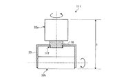
実施形態3の移動ロボット111において、図16に示す各肢体ユニット12は、複数の肢体側駆動軸32のうち、所定の第1駆動軸32aと、第1駆動軸32aに対して所定の角度分だけ傾斜させた第2駆動軸32bと、を有している。ここで、第1駆動軸32a及び第2駆動軸32bは、ロール軸32r、ピッチ軸32p及びヨー軸32yのいずれであってもよい。また、肢体ユニット12は、内側に第2駆動軸32bを保持すると共に、外側に第1駆動軸32aが取り付けられる保持フレーム33を有する。ここで、保持フレーム33は、基端関節モジュール35の保持フレーム41、中間関節モジュール36の保持フレーム42及び先端関節モジュール37の保持フレーム43のいずれであってもよい。
In the
保持フレーム33には、保持フレーム33の外面に対して内側に窪んで形成される窪み穴112が形成されている。この窪み穴112には、第1駆動軸32aの一端部が収容される。第1駆動軸32aの一端部には、径方向の外側に突出する円環形状のフランジ部113が形成され、フランジ部113と窪み穴112の周縁部とが、締結部材114によって締結されることで、第1駆動軸32aが保持フレーム33に固定される。
The holding
また、図17に示す各肢体ユニット12において、保持フレーム33には、保持フレーム33の外面に対して内側に窪んで貫通形成される雌ねじ部116が形成されている。この雌ねじ部116には、第1駆動軸32aの一端部が収容される。第1駆動軸32aの一端部には、雌ねじ部116に螺合する雄ねじ部117が形成され、雌ねじ部116と雄ねじ部117とが締結されることで、第1駆動軸32aが保持フレーム33に固定される。
In each
以上のように、実施形態3によれば、第1駆動軸32aの一部を窪み穴112または雌ねじ部116に収容できる分、第1駆動軸32aの軸方向において、第1駆動軸32a及び第2駆動軸32bを含む長さlを短くすることができるため、肢体ユニット12のコンパクト化を図ることができる。
As described above, according to the third embodiment, the
[実施形態4]
次に、図18から図20を参照して、実施形態4に係る移動ロボット121について説明する。図18は、実施形態4の移動ロボットに取り付けられる先端ツールの一例を示す外観斜視図である。図19は、はしごの踏桟に引っ掛けられる先端ツールの断面図である。図20は、把持部の展開前後における先端ツールの説明図である。なお、実施形態4でも、重複した記載を避けるべく、実施形態1から3と異なる部分について説明し、実施形態1から3と同様の構成である部分については、同じ符号を付して説明する。
[Embodiment 4]
Next, the
実施形態4に係る移動ロボット121の肢体ユニット12に取り付けられる、図18から図20に示す先端ツール13cは、図3の先端ツール13a及び図4の先端ツール13bの両方の機能を兼ね備えたものとなっている。先端ツール13cは、肢体ユニット12に着脱自在に取り付けられる接続部125と、接続部125を挟んで一方側に設けられるつま先部126と、を有する。なお、接続部125を挟んで他方側に設けられるかかと部は、つま先部126と同様の構成としてもよいし、図3の先端ツール13aのかかと部53、または図4の先端ツール13bのかかと部63と同様の構成としてもよく、特に限定されない。
The
先端ツール13cは、肢体ユニット12への取付側とは反対側の部位が、地面に接する部位となっており、地面に接する部位には、平坦面P3が形成されている。平坦面P3には、先端ツール13aと同様に、係止溝(図示省略)及び鈎溝55が形成されている。鈎溝55は、つま先部126の位置に形成されている。ここで、つま先部126は、つま先部126とかかと部とをつなぐ方向に直交する方向において、空間部129を挟んで2つに分岐して形成されることで、2つの分岐部127が形成される。この2つの分岐部127は、鈎溝55が形成されていることから、鈎爪状に形成されている。また、先端ツール13cには、空間部129の接続部125側の部位に、平坦面P3と同一面を有する係止部128が形成されている。このため、先端ツール13cのつま先部126を、はしご71の踏桟73に引っ掛ける場合、図19に示すように、踏桟73を挟んで一方側に2つの分岐部127が位置し、踏桟73を挟んで他方側に係止部128が位置するように、分岐部127の鈎溝55に踏桟73を収容する。
The
ここで、図19に示すように、踏桟73が延在する方向において、係止部128は、2つの分岐部127の間に配置されている。このため、踏桟73の延在する方向に対して、つま先部126の位置決め誤差により先端ツール13cの向きが大きくずれた状態でも、先端ツール13cにより踏桟73を引っ掛けることが可能となる。
Here, as shown in FIG. 19, the locking
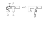
また、この先端ツール13cの空間部129には、対象物を把持可能な把持部130が収容可能に設けられている。把持部130は、複数本の指を有しており、各分岐部127の形状に沿わせた状態で、空間部129に収容されている。この把持部130は、図20に示すように、作業時において複数の指が展開される一方で、歩行時において複数の指が折り畳まれる。
In addition, the
以上のように、実施形態4によれば、先端ツール13cを用いて、二足歩行または四足歩行を行う場合には、平坦面P3を地面に接地させることができるため、移動時の安定性を高めることができる。また、先端ツール13cを用いて、はしご71を昇降する場合には、下方側の2つの肢体ユニット12に取り付けられる先端ツール13cの係止溝に、はしご71の踏桟73を係止することができ、上方側の2つの肢体ユニット12に取り付けられる先端ツール13cの鈎溝55に、はしご71の踏桟73または支柱72を引っ掛けることができる。このため、はしご71の昇降を好適に行うことができる。さらに、把持部130により対象物を把持することができるため、把持部130による作業を行うことが可能となる。このとき、把持部130は、空間部129に収容することができるため、把持部130がはしご71の昇降を阻害することを抑制することができる。
As described above, according to the fourth embodiment, when performing bipedal walking or quadrupedal walking using the
なお、図21に示す先端ツール13d及び図22に示す先端ツール13eを適用してもよい。図21及び図22は、移動ロボットに取り付けられる先端ツールの一例を示す模式図である。
Note that the
図21に示す先端ツール13dは、肢体ユニット12に着脱自在に取り付けられる接続部135と、接続部135を挟んで一方側に設けられるつま先部136と、接続部135を挟んで他方側に設けられるかかと部137とを有する。また、先端ツール13dは、地面に接する部位にカメラ(撮像装置)138が設けられ、カメラ138は、接続部135の位置に設けられている。
The
図21の先端ツール13dを用いれば、カメラ138により撮像された画像により先端ツール13d周りの移動環境を、移動ロボット121を操作するオペレータが把握し易いものとすることができる。
If the
図22に示す先端ツール13eは、肢体ユニット12に着脱自在に取り付けられる接続部145と、接続部145を挟んで一方側に設けられるつま先部146と、接続部145を挟んで他方側に設けられるかかと部147とを有する。つま先部146は、つま先立ちして移動するときに地面に接する部位が、曲面148となっている。
The
図22の先端ツール13eを用いれば、例えば、四足歩行時において、肢体ユニット12の複数の肢体側駆動軸32のうち、一部の肢体側駆動軸32の駆動を停止した場合であっても、先端ツール13eのつま先部146において、曲面148となる部位を地面に確実に接地させることができる。このため、一部の肢体側駆動軸32の駆動を停止できる分、電力消費を抑制することができる。
If the
1 移動ロボット
11 胴体ユニット
12 肢体ユニット
13 先端ツール
21 胴体フレーム
22 胴体側駆動軸
22p ピッチ軸
22r ロール軸
31 関節モジュール
32 肢体側駆動軸
32r ロール軸
32p ピッチ軸
32y ヨー軸
35 基端関節モジュール
36 中間関節モジュール
37 先端関節モジュール
51 接続部
52 つま先部
53 かかと部
54 係止溝
55 鈎溝
61 接続部
62 つま先部
63 かかと部
64 把持部
71 はしご
72 支柱
73 踏桟
74 保護柵
101 移動ロボット(実施形態2)
102 車輪
111 移動ロボット(実施形態3)
112 窪み穴
113 フランジ部
114 締結部材
116 雌ねじ部
117 雄ねじ部
121 移動ロボット(実施形態4)
125 接続部
126 つま先部
127 分岐部
128 係止部
129 空間部
130 把持部
138 カメラ
148 曲面
DESCRIPTION OF SYMBOLS 1
102
DESCRIPTION OF
125 connecting
Claims (21)
正面及び背面を有する胴体ユニットと、
基端側が前記胴体ユニットに接続され、複数の駆動軸を有する複数の肢体ユニットと、
前記肢体ユニットの先端側に設けられる先端ツールと、を備え、
前記胴体ユニットの前記正面及び前記背面が対向する方向を厚さ方向とし、前記厚さ方向に直交する方向を長さ方向とし、前記厚さ方向及び前記長さ方向に直交する方向を幅方向とし、前記長さ方向の両端側の端面を、上面及び下面とし、前記幅方向の両端側の端面を、左側面及び右側面とすると、
前記複数の肢体ユニットは、同一のユニットとなっており、
前記胴体ユニット及び前記複数の肢体ユニットは、前記胴体ユニットの前記厚さ方向の中央を挟んで、前記正面側の移動動作と前記背面側の移動動作とが対称な動作となるように、前記正面側と前記背面側とを切り替えて移動可能となっていることを特徴とする移動ロボット。 In a mobile robot having a plurality of different movement forms,
A fuselage unit having a front surface and a back surface;
A plurality of limb units having a base end side connected to the trunk unit and having a plurality of drive shafts;
A tip tool provided on the tip side of the limb body unit,
A direction in which the front surface and the back surface of the fuselage unit are opposed to each other is a thickness direction, a direction orthogonal to the thickness direction is a length direction, and a direction orthogonal to the thickness direction and the length direction is a width direction. The end surfaces on both ends in the length direction are the upper surface and the lower surface, and the end surfaces on both ends in the width direction are the left side and the right side,
The plurality of limb body units are the same unit,
The front unit and the plurality of limb units are arranged such that the front side movement operation and the back side movement operation are symmetrical with respect to the center of the trunk unit in the thickness direction. A mobile robot characterized in that it is movable by switching between the side and the back side.
前記胴体ユニットの前記長さ方向を軸方向として回転する方向をロール方向とし、前記胴体ユニットの前記幅方向を軸方向として回転する方向をピッチ方向とし、前記胴体ユニットの前記厚さ方向を軸方向として回転する方向をヨー方向とすると、
前記肢体ユニットは、前記胴体ユニットの前記厚さ方向に伸ばした状態において、基端側に設けられる少なくとも2つの前記駆動軸が、前記ロール方向の前記駆動軸及び前記ピッチ方向の前記駆動軸であることを特徴とする請求項1または2に記載の移動ロボット。 The plurality of limb units are attached to at least two limb units, respectively, with respect to the left side surface and the right side surface of the trunk unit,
The direction rotating with the length direction of the body unit as the axial direction is the roll direction, the direction rotating with the width direction of the body unit as the axial direction is the pitch direction, and the thickness direction of the body unit is the axial direction Assuming that the direction of rotation is the yaw direction,
In the state where the limb body unit is extended in the thickness direction of the trunk unit, at least two of the drive shafts provided on the base end side are the drive shaft in the roll direction and the drive shaft in the pitch direction. The mobile robot according to claim 1 or 2, characterized in that:
前記肢体ユニットは、前記胴体ユニットの前記厚さ方向に伸ばした状態において、先端側に設けられる少なくとも2つの前記駆動軸が、前記ロール方向の前記駆動軸及び前記ピッチ方向の前記駆動軸であることを特徴とする請求項1または2に記載の移動ロボット。 The direction rotating with the length direction of the body unit as the axial direction is the roll direction, the direction rotating with the width direction of the body unit as the axial direction is the pitch direction, and the thickness direction of the body unit is the axial direction Assuming that the direction of rotation is the yaw direction,
In the state where the limb body unit is extended in the thickness direction of the trunk unit, at least two of the drive shafts provided on the distal end side are the drive shaft in the roll direction and the drive shaft in the pitch direction. The mobile robot according to claim 1 or 2.
前記胴体ユニットの前記長さ方向を軸方向として回転する方向をロール方向とし、前記胴体ユニットの前記幅方向を軸方向として回転する方向をピッチ方向とし、前記胴体ユニットの前記厚さ方向を軸方向として回転する方向をヨー方向とすると、
前記肢体ユニットは、前記胴体ユニットの前記厚さ方向に伸ばした状態において、基端側に設けられる少なくとも2つの前記駆動軸が、前記ロール方向の前記駆動軸及び前記ピッチ方向の前記駆動軸であり、先端側に設けられる少なくとも2つの前記駆動軸が、前記ロール方向の前記駆動軸及び前記ピッチ方向の前記駆動軸であり、基端側に設けられる2つの前記駆動軸と先端側に設けられる2つの前記駆動軸との間に設けられる少なくとも3つの前記駆動軸が、2つのヨー方向の前記駆動軸及びピッチ方向の前記駆動軸であることを特徴とする請求項1または2に記載の移動ロボット。 The plurality of limb units are attached to at least two limb units, respectively, with respect to the left side surface and the right side surface of the trunk unit,
The direction rotating with the length direction of the body unit as the axial direction is the roll direction, the direction rotating with the width direction of the body unit as the axial direction is the pitch direction, and the thickness direction of the body unit is the axial direction Assuming that the direction of rotation is the yaw direction,
In the state where the limb body unit is extended in the thickness direction of the trunk unit, at least two of the drive shafts provided on the base end side are the drive shaft in the roll direction and the drive shaft in the pitch direction. The at least two drive shafts provided on the distal end side are the drive shaft in the roll direction and the drive shaft in the pitch direction, and the two drive shafts provided on the proximal end side and 2 provided on the distal end side. The mobile robot according to claim 1, wherein at least three of the drive shafts provided between the two drive shafts are the two drive shafts in the yaw direction and the drive shaft in the pitch direction. .
前記胴体ユニットは、前記ピッチ方向の駆動軸と、前記ロール方向の駆動軸との少なくとも一方を有することを特徴とする請求項1から5のいずれか1項に記載の移動ロボット。 The direction rotating with the length direction of the body unit as the axial direction is the roll direction, the direction rotating with the width direction of the body unit as the axial direction is the pitch direction, and the thickness direction of the body unit is the axial direction Assuming that the direction of rotation is the yaw direction,
The mobile robot according to claim 1, wherein the body unit has at least one of a drive shaft in the pitch direction and a drive shaft in the roll direction.
複数の前記関節モジュールに設けられる複数の前記駆動軸は、同一となっていることを特徴とする請求項8に記載の移動ロボット。 While the joint modules of the limb body unit are different types,
The mobile robot according to claim 8, wherein the plurality of drive shafts provided in the plurality of joint modules are the same.
複数の前記駆動軸のうち、所定の前記駆動軸である第1駆動軸と、
複数の前記駆動軸のうち、前記第1駆動軸に対して所定の角度分だけ傾斜させた第2駆動軸と、
内側に前記第2駆動軸を保持すると共に、外側に前記第1駆動軸が取り付けられる保持フレームと、を有し、
前記保持フレームは、前記保持フレームの外面に対して内側に窪んで形成される窪み部を有し、
前記第1駆動軸は、一部が前記窪み部に収容されて、前記保持フレームに取り付けられることを特徴とする請求項1から9のいずれか1項に記載の移動ロボット。 The limb body unit is
A first drive shaft that is the predetermined drive shaft among the plurality of drive shafts;
A second drive shaft that is inclined by a predetermined angle with respect to the first drive shaft among the plurality of drive shafts;
A holding frame that holds the second drive shaft on the inner side and is attached to the first drive shaft on the outer side,
The holding frame has a recess formed to be recessed inward with respect to the outer surface of the holding frame;
10. The mobile robot according to claim 1, wherein a part of the first drive shaft is accommodated in the recess and attached to the holding frame. 11.
前記平坦面には、水平方向に伸びる棒状部材に係止可能な係止溝と、前記棒状部材に引っ掛けることが可能な鈎溝と、が並んで形成されていることを特徴とする請求項1から11のいずれか1項に記載の移動ロボット。 The tip tool is formed on a flat surface in contact with the ground,
2. The flat surface is formed with a locking groove that can be locked to a bar-shaped member extending in a horizontal direction and a ridge groove that can be hooked on the bar-shaped member side by side. The mobile robot according to any one of 1 to 11.
前記平坦面とは反対側の部位には、対象物を把持可能な把持部が設けられていることを特徴とする請求項1から11のいずれか1項に記載の移動ロボット。 The tip tool is formed on a flat surface in contact with the ground,
The mobile robot according to any one of claims 1 to 11, wherein a grip portion capable of gripping an object is provided in a portion opposite to the flat surface.
前記平坦面には、棒状部材に係止可能な係止溝と、前記棒状部材に引っ掛けることが可能な鈎溝と、が平行に形成され、
前記平坦面内における前記鈎溝側の部位は、空間を挟んで2つに分岐して形成され、
前記空間には、対象物を把持可能な把持部が収容可能に設けられていることを特徴とする請求項1から11のいずれか1項に記載の移動ロボット。 The tip tool has a portion that is in contact with the ground formed on a flat surface, and a portion opposite to the flat surface is connected to the limb body unit,
On the flat surface, a locking groove that can be locked to the rod-shaped member and a ridge groove that can be hooked on the rod-shaped member are formed in parallel,
The portion on the side of the groove in the flat surface is formed by branching into two with a space in between,
The mobile robot according to claim 1, wherein a grip portion capable of gripping an object is provided in the space so as to be accommodated.
前記肢体ユニットに接続される接続部と、
前記接続部を挟んで一方側に設けられるつま先部と、
前記接続部を挟んで他方側に設けられるかかと部と、を有し、
前記つま先部は、つま先立ちして移動するときに地面に接する部位が、曲面となっていることを特徴とする請求項1から15のいずれか1項に記載の移動ロボット。 The tip tool is
A connecting portion connected to the limb body unit;
A toe portion provided on one side across the connecting portion;
A heel part provided on the other side across the connection part,
The mobile robot according to claim 1, wherein the toe portion has a curved surface in contact with the ground when the toe portion moves while standing on the toe.
地面に接する部位は、平坦面に形成されており、
前記平坦面には、水平方向に伸びる棒状部材に係止可能な係止溝と、前記棒状部材に引っ掛けることが可能な鈎溝と、が並んで形成されていることを特徴とする先端ツール。 A tip tool attached to a mobile robot having a plurality of different types of movement comprising a torso unit and a plurality of limbs units whose proximal end is connected to the torso unit,
The part in contact with the ground is formed on a flat surface,
A tip tool characterized in that a locking groove that can be locked to a horizontally extending rod-like member and a ridge groove that can be hooked on the rod-like member are formed side by side on the flat surface.
地面に接する部位は、平坦面に形成されており、
前記平坦面とは反対側の部位には、対象物を把持可能な把持部が設けられていることを特徴とする先端ツール。 A tip tool attached to a mobile robot having a plurality of different types of movement comprising a torso unit and a plurality of limbs units whose proximal end is connected to the torso unit,
The part in contact with the ground is formed on a flat surface,
A tip tool characterized in that a grip portion capable of gripping an object is provided at a portion opposite to the flat surface.
地面に接する部位は、平坦面に形成され、前記平坦面とは反対側の部位は、前記肢体ユニットに接続され、
前記平坦面には、棒状部材に係止可能な係止溝と、前記棒状部材に引っ掛けることが可能な鈎溝と、が平行に形成され、
前記平坦面内における前記鈎溝側の部位は、空間を挟んで2つに分岐して形成され、
前記空間には、対象物を把持可能な把持部が収容可能に設けられていることを特徴とする先端ツール。 A tip tool attached to a mobile robot having a plurality of different types of movement comprising a torso unit and a plurality of limbs units whose proximal end is connected to the torso unit,
The part in contact with the ground is formed on a flat surface, the part opposite to the flat surface is connected to the limb body unit,
On the flat surface, a locking groove that can be locked to the rod-shaped member and a ridge groove that can be hooked on the rod-shaped member are formed in parallel,
The portion on the side of the groove in the flat surface is formed by branching into two with a space in between,
A tip tool characterized in that a grip portion capable of gripping an object is provided in the space so as to be accommodated.
前記接続部を挟んで一方側に設けられるつま先部と、
前記接続部を挟んで他方側に設けられるかかと部と、を有し、
前記つま先部は、つま先立ちして移動するときに地面に接する部位が、曲面となっていることを特徴とする請求項17から20のいずれか1項に記載の先端ツール。 A connecting portion connected to the limb body unit;
A toe portion provided on one side across the connecting portion;
A heel part provided on the other side across the connection part,
The tip tool according to any one of claims 17 to 20, wherein the toe portion has a curved surface in contact with the ground when moving while standing on the toe.
Priority Applications (3)
| Application Number | Priority Date | Filing Date | Title |
|---|---|---|---|
| JP2014263528A JP6593991B2 (en) | 2014-12-25 | 2014-12-25 | Mobile robot and tip tool |
| US14/833,521 US9845122B2 (en) | 2014-12-25 | 2015-08-24 | Mobile robot and front end tool |
| US15/290,368 US10220897B2 (en) | 2014-12-25 | 2016-10-11 | Mobile robot and front end tool |
Applications Claiming Priority (1)
| Application Number | Priority Date | Filing Date | Title |
|---|---|---|---|
| JP2014263528A JP6593991B2 (en) | 2014-12-25 | 2014-12-25 | Mobile robot and tip tool |
Publications (2)
| Publication Number | Publication Date |
|---|---|
| JP2016120584A true JP2016120584A (en) | 2016-07-07 |
| JP6593991B2 JP6593991B2 (en) | 2019-10-23 |
Family
ID=56163331
Family Applications (1)
| Application Number | Title | Priority Date | Filing Date |
|---|---|---|---|
| JP2014263528A Expired - Fee Related JP6593991B2 (en) | 2014-12-25 | 2014-12-25 | Mobile robot and tip tool |
Country Status (2)
| Country | Link |
|---|---|
| US (2) | US9845122B2 (en) |
| JP (1) | JP6593991B2 (en) |
Cited By (4)
| Publication number | Priority date | Publication date | Assignee | Title |
|---|---|---|---|---|
| WO2019123769A1 (en) * | 2017-12-19 | 2019-06-27 | ソニー株式会社 | Limb unit and robot |
| US10994427B2 (en) | 2018-04-05 | 2021-05-04 | Fanuc Corporation | Robot with safety fence and robot system |
| KR20230153050A (en) * | 2022-04-28 | 2023-11-06 | 주식회사 오리온이엔씨 | Multi-purpose monitoring self-driving robot capable of rough driving |
| JP2023548924A (en) * | 2021-01-28 | 2023-11-21 | ▲騰▼▲訊▼科技(深▲セン▼)有限公司 | Robot motion control method, device, robot, and computer program |
Families Citing this family (20)
| Publication number | Priority date | Publication date | Assignee | Title |
|---|---|---|---|---|
| JP6228097B2 (en) * | 2014-10-06 | 2017-11-08 | 本田技研工業株式会社 | Mobile robot |
| JP6514520B2 (en) * | 2015-02-17 | 2019-05-15 | 本田技研工業株式会社 | Hand device, robot arm and robot equipped with the same |
| US10059392B1 (en) * | 2016-06-27 | 2018-08-28 | Boston Dynamics, Inc. | Control of robotic devices with non-constant body pitch |
| US10456906B2 (en) * | 2016-07-08 | 2019-10-29 | ETAK Systems, LLC | Mechanical tower climber for operations on cell towers |
| CN106114673A (en) * | 2016-08-02 | 2016-11-16 | 安徽工程大学机电学院 | A kind of climbing robot |
| CN106737848B (en) * | 2016-12-29 | 2023-08-04 | 深圳市优必选科技有限公司 | Leg structure and humanoid robot |
| JP3228266U (en) * | 2017-06-19 | 2020-10-22 | ジョンルイ フーニン ロボティクス (シェンヤン) カンパニー リミテッド | Robots configured to perform actions for social interaction with humans |
| CN107336762A (en) * | 2017-06-30 | 2017-11-10 | 天津大学 | One kind, which is reduced, drives diarthrodial four-leg bionic robot |
| US10421510B2 (en) * | 2017-07-25 | 2019-09-24 | Sphero, Inc. | Three-legged robotic apparatus |
| CN107571933B (en) * | 2017-08-15 | 2020-08-18 | 北京航空航天大学 | A suspension system for quadruped robot |
| US11025132B2 (en) * | 2018-01-16 | 2021-06-01 | 2576150 Ontario Corp. | Case for a servomotor |
| CN113348129B (en) * | 2018-12-03 | 2023-10-20 | 昆士兰大学 | Gyroscope-stabilized leg type robot |
| CN111267991B (en) * | 2020-01-19 | 2021-05-11 | 之江实验室 | A design method for the structure size of the lower limbs of a biped robot |
| CN111846010A (en) * | 2020-08-04 | 2020-10-30 | 北京理工大学 | A quadruped robot based on mid-waist assisted motion |
| CN113064421B (en) * | 2021-03-08 | 2023-03-31 | 上海工程技术大学 | Portable multi-mode mobile robot |
| CN113200101A (en) * | 2021-05-07 | 2021-08-03 | 华中师范大学 | Quadruped robot |
| CN114083553B (en) * | 2022-01-06 | 2023-05-26 | 上海工程技术大学 | Polymorphic mobile robot |
| EP4261111A1 (en) * | 2022-04-13 | 2023-10-18 | Siemens Energy Global GmbH & Co. KG | Robotic inspection tool for use in confined spaces |
| CN117018639A (en) * | 2023-08-18 | 2023-11-10 | 蔡泽銮 | An assembled robot toy |
| CN117284389A (en) * | 2023-11-06 | 2023-12-26 | 燕山大学 | Crawling lizard-like robot adapted to multiple environments |
Citations (9)
| Publication number | Priority date | Publication date | Assignee | Title |
|---|---|---|---|---|
| JPS62131886A (en) * | 1985-12-03 | 1987-06-15 | Toshiba Corp | Multileg traveling machine |
| JPH0593778U (en) * | 1992-05-20 | 1993-12-21 | 本田技研工業株式会社 | Legged mobile robot with visual sensor |
| JPH06226661A (en) * | 1993-02-09 | 1994-08-16 | Toshiba Corp | Robot modules and robots |
| JP2004174704A (en) * | 2002-11-14 | 2004-06-24 | Sony Corp | Actuator device and multi-axis robot |
| JP2006062057A (en) * | 2004-08-30 | 2006-03-09 | Honda Motor Co Ltd | Leg type mobile robot |
| CN101088835A (en) * | 2007-06-15 | 2007-12-19 | 哈尔滨工程大学 | Modular Mechanical Crab |
| JP2010005718A (en) * | 2008-06-25 | 2010-01-14 | Nsk Ltd | Leg type robot |
| JP2012157968A (en) * | 2011-02-02 | 2012-08-23 | Kochi Univ Of Technology | Multiform robot |
| JP2014213426A (en) * | 2013-04-26 | 2014-11-17 | 株式会社東芝 | Mobile robot |
Family Cites Families (25)
| Publication number | Priority date | Publication date | Assignee | Title |
|---|---|---|---|---|
| US4527650A (en) * | 1983-03-18 | 1985-07-09 | Odetics, Inc. | Walking machine |
| US4637494A (en) * | 1983-11-15 | 1987-01-20 | Kabushiki Kaisha Toshiba | Apparatus for moving carriages along ladders |
| US5040626A (en) * | 1986-02-12 | 1991-08-20 | Nathaniel A. Hardin | Walking robots having double acting fluid driven twistor pairs as combined joints and motors and method of locomotion |
| US4793439A (en) * | 1987-07-28 | 1988-12-27 | Crawford Homer S | Apparatus for climbing trees, poles and the like and being remotely controlled from ground elevation |
| US5005658A (en) * | 1988-12-22 | 1991-04-09 | Carnegie-Mellon University | Orthogonal legged walking robot |
| IT1230248B (en) * | 1989-06-08 | 1991-10-18 | Luigi Paris | CLIMBING ROBOT, MOBILE ALONG A TRUSS STRUCTURE, IN PARTICULAR OF A HIGH VOLTAGE ELECTRIC LINE POLE. |
| JP2520019B2 (en) * | 1989-06-29 | 1996-07-31 | 本田技研工業株式会社 | Drive controller for legged mobile robot |
| US5219410A (en) * | 1989-10-20 | 1993-06-15 | Commissariat A L'energie Atomique | Device for transmitting movement between a solid and a member, in particular for a robot able to be moved on legs |
| IT1273858B (en) * | 1994-12-22 | 1997-07-11 | Giancarlo Zamagni | ANTHROPOD LOCOMATION MACHINE ON A SUPERFCIE |
| JPH09168982A (en) | 1995-12-20 | 1997-06-30 | Mitsubishi Heavy Ind Ltd | Articulated robot |
| JP3662996B2 (en) * | 1996-01-25 | 2005-06-22 | 本田技研工業株式会社 | Walking control device for legged mobile robot |
| US6243623B1 (en) * | 1997-01-31 | 2001-06-05 | Honda Giken Kogyo Kabushiki Kaisha | Leg type mobile robot control apparatus |
| IL138695A (en) * | 2000-09-26 | 2004-08-31 | Rafael Armament Dev Authority | Unmanned mobile device |
| JP3824608B2 (en) * | 2001-08-01 | 2006-09-20 | ソニー株式会社 | Legged mobile robot and its motion control method |
| KR100541433B1 (en) * | 2002-12-23 | 2006-01-11 | 삼성전자주식회사 | 2-footed walking robot |
| US7086502B2 (en) * | 2004-02-24 | 2006-08-08 | Palo Alto Research Center Incorporated | Transport apparatus and method having conformable gripping capability |
| US7734375B2 (en) * | 2004-06-09 | 2010-06-08 | Boston Dynamics | Robot and robot leg mechanism |
| JP4280999B2 (en) | 2004-07-02 | 2009-06-17 | 独立行政法人産業技術総合研究所 | Robot system |
| WO2006011577A1 (en) * | 2004-07-30 | 2006-02-02 | Tmsuk Co., Ltd. | Multi-point ground contact type foot part support mechanism, bipedal walking robot having the support mechanism, and control structure for the robot |
| US7339340B2 (en) * | 2005-03-23 | 2008-03-04 | Harris Corporation | Control system and related method for multi-limbed, multi-legged robot |
| US20080109115A1 (en) * | 2006-11-03 | 2008-05-08 | Michael Zin Min Lim | Dynamic force controller for multilegged robot |
| FR2929228B1 (en) * | 2008-03-28 | 2010-06-18 | Thales Sa | POKER ROBOT ROBOT. |
| US8100205B2 (en) * | 2010-04-06 | 2012-01-24 | Robotex Inc. | Robotic system and method of use |
| US8657042B2 (en) * | 2010-10-04 | 2014-02-25 | China Industries Limited | Walking machine |
| AU2011318231B2 (en) * | 2010-10-19 | 2013-05-02 | White Puma Pty Limited | A device for traversing an object |
-
2014
- 2014-12-25 JP JP2014263528A patent/JP6593991B2/en not_active Expired - Fee Related
-
2015
- 2015-08-24 US US14/833,521 patent/US9845122B2/en not_active Expired - Fee Related
-
2016
- 2016-10-11 US US15/290,368 patent/US10220897B2/en active Active
Patent Citations (9)
| Publication number | Priority date | Publication date | Assignee | Title |
|---|---|---|---|---|
| JPS62131886A (en) * | 1985-12-03 | 1987-06-15 | Toshiba Corp | Multileg traveling machine |
| JPH0593778U (en) * | 1992-05-20 | 1993-12-21 | 本田技研工業株式会社 | Legged mobile robot with visual sensor |
| JPH06226661A (en) * | 1993-02-09 | 1994-08-16 | Toshiba Corp | Robot modules and robots |
| JP2004174704A (en) * | 2002-11-14 | 2004-06-24 | Sony Corp | Actuator device and multi-axis robot |
| JP2006062057A (en) * | 2004-08-30 | 2006-03-09 | Honda Motor Co Ltd | Leg type mobile robot |
| CN101088835A (en) * | 2007-06-15 | 2007-12-19 | 哈尔滨工程大学 | Modular Mechanical Crab |
| JP2010005718A (en) * | 2008-06-25 | 2010-01-14 | Nsk Ltd | Leg type robot |
| JP2012157968A (en) * | 2011-02-02 | 2012-08-23 | Kochi Univ Of Technology | Multiform robot |
| JP2014213426A (en) * | 2013-04-26 | 2014-11-17 | 株式会社東芝 | Mobile robot |
Cited By (8)
| Publication number | Priority date | Publication date | Assignee | Title |
|---|---|---|---|---|
| WO2019123769A1 (en) * | 2017-12-19 | 2019-06-27 | ソニー株式会社 | Limb unit and robot |
| US10994427B2 (en) | 2018-04-05 | 2021-05-04 | Fanuc Corporation | Robot with safety fence and robot system |
| JP2023548924A (en) * | 2021-01-28 | 2023-11-21 | ▲騰▼▲訊▼科技(深▲セン▼)有限公司 | Robot motion control method, device, robot, and computer program |
| EP4261625A4 (en) * | 2021-01-28 | 2024-05-29 | Tencent Technology (Shenzhen) Company Limited | ROBOT MOTION CONTROL METHOD AND APPARATUS, ROBOT AND STORAGE MEDIUM |
| JP7531710B2 (en) | 2021-01-28 | 2024-08-09 | ▲騰▼▲訊▼科技(深▲セン▼)有限公司 | Robot motion control method, device, robot, and computer program |
| US12330309B2 (en) | 2021-01-28 | 2025-06-17 | Tencent Technology (Shenzhen) Company Limited | Robot motion control method and apparatus |
| KR20230153050A (en) * | 2022-04-28 | 2023-11-06 | 주식회사 오리온이엔씨 | Multi-purpose monitoring self-driving robot capable of rough driving |
| KR102683381B1 (en) * | 2022-04-28 | 2024-07-09 | 주식회사 오리온이엔씨 | Multi-purpose monitoring self-driving robot capable of rough driving |
Also Published As
| Publication number | Publication date |
|---|---|
| US10220897B2 (en) | 2019-03-05 |
| US9845122B2 (en) | 2017-12-19 |
| JP6593991B2 (en) | 2019-10-23 |
| US20160185405A1 (en) | 2016-06-30 |
| US20170029049A1 (en) | 2017-02-02 |
Similar Documents
| Publication | Publication Date | Title |
|---|---|---|
| JP6593991B2 (en) | Mobile robot and tip tool | |
| US11026852B2 (en) | Supporting structure | |
| CN106737578A (en) | A kind of quadruped robot | |
| US20170321414A1 (en) | Solar panel truss deployable from moving carrier | |
| KR20090083495A (en) | Walking robot | |
| CN103359198A (en) | All-directional horizontal-posture stair climbing robot, zero-radius turning method and stair climbing method | |
| JPWO2012104895A1 (en) | Articulated arm robot, control method and control program | |
| CN100469645C (en) | Variable structure legged wheeled robot bug | |
| CN115151175A (en) | Robotic device with tri-star wheel and actuator arm and method of navigating a surface with a robotic device | |
| US10399238B2 (en) | Robot having a base body, a shoulder joint mechanism assembly, and a movable link coupled to the base body through the shoulder joint mechanism assembly | |
| WO2014132733A1 (en) | Stepladder | |
| JPH1159515A (en) | Crawling carriage | |
| CN107030675B (en) | Powered Exoskeletons and Stabilizing Structures | |
| CN108674513A (en) | Allosteric state wheel leg Mobile working machine people | |
| KR100855365B1 (en) | bench | |
| CN110304169B (en) | Double-support-leg-set walking platform and control method thereof | |
| JP2007125638A (en) | Additional device for walking robot and walking robot | |
| CN209320987U (en) | A kind of construction collapsed transportable vehicle | |
| CN209757312U (en) | wheel-leg type multi-mode inspection search and rescue robot | |
| CN211201723U (en) | Ladder | |
| KR101066453B1 (en) | robot | |
| JP2015100904A (en) | Remote work automatic machine and moving method thereof | |
| KR101307230B1 (en) | Escalator for stepping board | |
| CN110450193B (en) | Walking support mechanism of biped walking robot | |
| CN115257992A (en) | Obstacle crossing device and obstacle crossing method suitable for pole-climbing robot capable of automatically loosening poles |
Legal Events
| Date | Code | Title | Description |
|---|---|---|---|
| A621 | Written request for application examination |
Free format text: JAPANESE INTERMEDIATE CODE: A621 Effective date: 20171222 |
|
| A977 | Report on retrieval |
Free format text: JAPANESE INTERMEDIATE CODE: A971007 Effective date: 20181219 |
|
| A131 | Notification of reasons for refusal |
Free format text: JAPANESE INTERMEDIATE CODE: A131 Effective date: 20190205 |
|
| A521 | Request for written amendment filed |
Free format text: JAPANESE INTERMEDIATE CODE: A523 Effective date: 20190405 |
|
| TRDD | Decision of grant or rejection written | ||
| A01 | Written decision to grant a patent or to grant a registration (utility model) |
Free format text: JAPANESE INTERMEDIATE CODE: A01 Effective date: 20190827 |
|
| A61 | First payment of annual fees (during grant procedure) |
Free format text: JAPANESE INTERMEDIATE CODE: A61 Effective date: 20190924 |
|
| R150 | Certificate of patent or registration of utility model |
Ref document number: 6593991 Country of ref document: JP Free format text: JAPANESE INTERMEDIATE CODE: R150 |
|
| R250 | Receipt of annual fees |
Free format text: JAPANESE INTERMEDIATE CODE: R250 |
|
| LAPS | Cancellation because of no payment of annual fees |