WO2019123769A1 - Limb unit and robot - Google Patents
Limb unit and robot Download PDFInfo
- Publication number
- WO2019123769A1 WO2019123769A1 PCT/JP2018/037050 JP2018037050W WO2019123769A1 WO 2019123769 A1 WO2019123769 A1 WO 2019123769A1 JP 2018037050 W JP2018037050 W JP 2018037050W WO 2019123769 A1 WO2019123769 A1 WO 2019123769A1
- Authority
- WO
- WIPO (PCT)
- Prior art keywords
- timing
- unit
- limb
- joints
- instruction information
- Prior art date
- Legal status (The legal status is an assumption and is not a legal conclusion. Google has not performed a legal analysis and makes no representation as to the accuracy of the status listed.)
- Ceased
Links
Images


Classifications
-
- B—PERFORMING OPERATIONS; TRANSPORTING
- B25—HAND TOOLS; PORTABLE POWER-DRIVEN TOOLS; MANIPULATORS
- B25J—MANIPULATORS; CHAMBERS PROVIDED WITH MANIPULATION DEVICES
- B25J13/00—Controls for manipulators
-
- B—PERFORMING OPERATIONS; TRANSPORTING
- B25—HAND TOOLS; PORTABLE POWER-DRIVEN TOOLS; MANIPULATORS
- B25J—MANIPULATORS; CHAMBERS PROVIDED WITH MANIPULATION DEVICES
- B25J5/00—Manipulators mounted on wheels or on carriages
Definitions
- the present disclosure relates to a limb unit and a robot.
- Patent Document 1 discloses a four-legged robot in which four leg modules are respectively attached to a body via joints. Each leg module is pivoted back and forth by an articulation motor provided on the body.
- the processing load of the four-legged robot main body when controlling the operation of each leg module is large.
- the four-legged robot main body in order to control the operation of each leg module, has to directly control the joint motor corresponding to the leg module provided in the body part. It does not.
- the present disclosure proposes a novel and improved limb unit and robot that can reduce the processing load on the main body when controlling the motion of individual joints.
- a control unit which causes the transmitting unit to transmit its own position and orientation information at the first timing to the main body based on the sensing result at the first timing of each of the plurality of joints.
- a receiving unit for receiving, from the main unit, operation instruction information at a second timing after the first timing based on position and orientation information of one's own at the timing of A limb unit is provided that controls the motion of each of the plurality of joints at the second timing based on motion instruction information at the second timing.
- a plurality of limb units and a body portion are provided, and each of the plurality of limb units includes a plurality of joints and a first timing of each of the plurality of joints included in the limb unit.
- a control unit that causes the transmitting unit to transmit position and orientation information of the limb unit at the first timing to the main unit based on a sensing result, and position and orientation information of the limb unit at the first timing,
- a receiving unit that receives, from the main body unit, operation instruction information of the limb unit at a second timing later than the first timing, and the control unit determines the limb unit at the second timing
- the robot controls the motion of each of the joints of the limb unit at the second timing based on the motion instruction information of It is subjected.
- the present disclosure it is possible to reduce the processing load on the main body when controlling the operation of each joint.
- the effect described here is not necessarily limited, and may be any effect described in the present disclosure.
- a plurality of components having substantially the same functional configuration may be distinguished by attaching different alphabets to the same reference numerals.
- a plurality of components having substantially the same functional configuration are distinguished as the leg unit 10a and the leg unit 10b as necessary.
- the leg unit 10a and the leg unit 10b are simply referred to as a leg unit 10 when it is not necessary to distinguish them.
- Comparative example >> The present disclosure can be implemented in various forms, as described in detail in “2. Detailed Description of the Embodiments” as an example. First, to clearly show the features of the embodiments according to the present disclosure, comparative examples of the present disclosure will be described.
- the robot 90 is a four-legged robot.
- the robot 90 has a body 900 and four legs 902.
- the torso unit 900 includes a control unit 904.
- the control unit 904 includes a processing circuit such as, for example, a central processing unit (CPU) or a graphical processing unit (GPU).
- the control unit 904 generally controls the operation of the robot 90.
- the control unit 904 controls the operation of an individual actuator disposed in each of the four legs 902.
- Each of the four legs 902 is configured as a link mechanism including a plurality of joints and a plurality of links.
- the plurality of joints include a hip joint connected to the trunk 900, a knee joint, an ankle joint, and the like.
- the plurality of links include a sole and a first link connecting to the ankle joint, a second link connecting the ankle joint and the knee joint, and a third link connecting the knee joint and the hip joint And so on.
- Each of the plurality of joints has, for example, one or more actuators capable of outputting a force for rotating the joint around the rotation axis of the joint.
- the control unit 904 of the robot 90 performs initial setting regarding various functions (applications etc.) mounted on the robot 90, for example (S901) .
- control unit 904 repeats the processing of S903 to S913 described below in a first cycle. Specifically, first, the control unit 904 determines that the time corresponding to the first period has elapsed since the previous sensing of the angle information of the individual actuators arranged in each of the four legs 902. It is determined whether or not (S903). While the time corresponding to the first cycle is not yet elapsed from the previous sensing (S903: No), the control unit 904 repeats the process of S903.
- the sensor units disposed at each joint of each of the four legs 902 are each joint It senses the angles of the individual actuators located inside.
- the sensor unit disposed in each joint senses the displacement amount of the angle of the actuator from the previous sensing with respect to each actuator in the joint.
- control part 904 acquires the sensing result by each sensor part from each sensor part (S905).
- the control unit 904 determines whether or not the time corresponding to the second cycle has elapsed since the previous calculation of the motion of the robot 90 whole body (S 907). While the time corresponding to the second cycle is not yet elapsed from the time of the previous calculation of the motion of the robot 90 (S 907: No), the control unit 904 is first included in each of the four legs 902 The force control calculation regarding the said joint is performed using the sensing result of S905 for every joint (S909).
- the control unit 904 calculates a torque output command value by each of the actuators disposed at each joint based on the calculation result of S909. For example, when S919 described later has been executed at least once, the control unit 150 calculates the value of the target torque to be output to the joint calculated in S919, and the sensing result acquired in the most recent S905. Based on the above, torque output command values by individual actuators disposed at each of all joints in the leg unit 10 are calculated (S911).
- control unit 904 controls the actuator so that the actuator corresponding to the torque output command value of the actuator calculated at S911 is output to the actuator arranged for each joint. (S913). Then, the control unit 904 repeats the processing after S903.
- the control unit 904 is acquired in the most recent S905, Included in each of the four legs 902 at the most recent time S905, based on the sensing results of the angles of the individual actuators located on each of the four legs 902, and the known kinematics algorithm. Position and posture of each joint to be calculated (S915).
- control unit 904 uses the known inverse kinematics algorithm and the known inverse dynamics algorithm according to the current exercise purpose to set the time corresponding to the time of the second cycle from the most recent time S905.
- the magnitude of the force to be exerted on the environment by the robot 90 is calculated (determined) (S917).
- the control unit 904 decomposes the magnitude of the force calculated in S917.
- the value of the target torque to be output to the joint is calculated at the elapse of the time corresponding to the time of the second cycle from the most recent time S905 (S919).
- the control unit 904 performs the processing of the above-described S911 and thereafter.
- the torso portion 900 alone is used to calculate the torque command values of the individual actuators included in each of the four legs 902, and individually based on the torque command values. Control the operation of the actuator. That is, the robot 90 centrally controls the operation of each of the four legs 902. For this reason, the processing load of the body 900 (that is, the main body of the robot 90) in controlling the movement of each joint included in each of the four legs 902 is large.
- the maintenance load on the robot 90 is large.
- a large number of cables are intricately wired between the body 900 and each of the four legs 902.
- the body 900 and the individual actuators in the individual legs 902 are directly connected by separate cables. That is, the wiring can be complicated and enormous.
- the work load is heavy.
- the robot 2 according to the embodiment of the present disclosure includes a plurality of leg units 10 and a main body 20. Then, each of the plurality of leg units 10 has the plurality of joints 100, and the corresponding leg unit at the first timing based on the sensing result of each of the plurality of joints 100 at the first timing. The position and orientation information of 10 is transmitted to the main body unit 20, and the operation instruction information at the second timing after the first timing is based on the position and orientation information of the leg unit 10 at the first timing. The operation of each of the plurality of joints 100 at the second timing is controlled based on the operation instruction information received from the unit 20 and the second timing.
- the processing load on the main body 20 when controlling the operation of each joint 100 can be reduced.
- the operation of the plurality of joints 100 included in each of the plurality of leg units 10 can be decentralized and controlled by the main body 20 and the leg unit 10. The contents of this embodiment will be sequentially described in detail below.
- the robot 2 may be, for example, a device capable of acting (for example, moving, gripping an object, etc.) autonomously using an electrical and / or magnetic action.
- the leg unit 10 is an example of a limb unit according to the present disclosure.
- the present disclosure is not limited to such an example, and the limb unit may be an arm unit.
- the arm unit may be configured as an arm unit that is attachable to and detachable from the main body unit 20.
- the limb unit according to the present disclosure is the leg unit 10 will be mainly described.
- the robot 2 may have four leg units 10.
- the present embodiment is not limited to such an example, and the number of leg units 10 may be any number (for example, one, two, or ten, etc.).
- the number of leg units 10 is four (for example, an example in which the robot 2 is a four-legged robot) will be described.
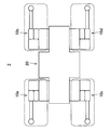
- FIG. 1 is a view schematically showing the appearance of the robot 2 as viewed from above.
- the robot 2 includes a main body 20 and four leg units 10.
- Each of the four leg units 10 may be configured to be removable with respect to the main body 20.
- leg units 10 may be all the same. However, the present invention is not limited to such an example, and for example, leg units 10 having different types of shaft configurations may be used in combination.
- the leg unit 10 includes a control unit 150, an energy supply port, and a communication unit 160.
- Control unit 150 may be configured to include, for example, processing circuits such as a central processing unit (CPU) and a graphics processing unit (GPU). Furthermore, the control unit 150 may be configured to include a memory such as a read only memory (ROM) or a random access memory (RAM). The specific function of the control unit 150 will be described later.
- processing circuits such as a central processing unit (CPU) and a graphics processing unit (GPU).
- GPU graphics processing unit
- the control unit 150 may be configured to include a memory such as a read only memory (ROM) or a random access memory (RAM). The specific function of the control unit 150 will be described later.
- ROM read only memory
- RAM random access memory
- the energy supply port is a port for receiving energy (for example, power, hydraulic pressure, water pressure, and / or air pressure, etc.) transmitted from the main body 20 to the leg unit 10.
- energy transmitted from the main unit 20 is transmitted to an actuator 110 and a motor driver 114 in each joint 100 described later via an energy supply port.
- the communication unit 160 is an example of a receiving unit and a transmitting unit according to the present disclosure.
- the communication unit 160 exchanges data with the main unit 20.
- Communication unit 160 includes, for example, a communication port for performing serial communication between main unit 20 and the corresponding leg unit 10, and a synchronization signal port for receiving a synchronization signal transmitted from main unit 20. It consists of The communication port and the synchronization signal port may be configured as a single port instead of being separately configured. The specific function of the communication unit 160 will be described later.
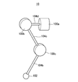
- FIG. 2 is a view schematically showing an example of an axial configuration of the leg unit 10.
- the leg unit 10 can be configured as a link mechanism including a plurality of joints and a plurality of links.
- the leg unit 10 has at least three joints 100 such as a hip joint Roll axis 100a, a hip joint Pitch axis 100b, and a knee joint Pitch axis 100c, and a toe 102.
- the leg unit 10 may further have an ankle joint (not shown) between the knee joint Pitch axis 100 c and the toe 102.
- the torque of the knee joint Pitch axis 100c may be transmitted to the ankle joint by a closed link mechanism.
- the leg unit 10 further includes a first link 104a including the toe 102, a second link 104b connecting the toe 102 and the knee joint Pitch axis 100c, and a second joint connecting the knee joint Pitch axis 100c and the hip joint Pitch axis 100b. It may have three links 104c, and a fourth link 104d connecting the hip joint Pitch axis 100b and the hip joint Roll axis 100a.
- the robot 2 is a leg unit when viewed from a fixed position of the leg unit 10 with respect to the main body 20 (for example, the position of the hip joint Roll axis 100a) for each leg unit 10.
- the positions of the ten toes 102 can be moved in three directions of vertical, horizontal and height.
- the robot 2 (more specifically, the main body 20) can apply force to any direction of the external world by changing the position and posture of each leg unit 10. Further, the body portion 20 can change the moment of force by each leg unit 10 according to, for example, the magnitude of the frictional force when each leg unit 10 contacts another object. Furthermore, since the toe trajectory of each leg unit 10 can be a three-dimensional free trajectory, the robot 2 can also overcome or avoid one or more obstacles.
- the first link 104a can be connected to the ankle joint.
- the second link 104b may be configured to couple the ankle joint and the knee joint Pitch axis 100c.
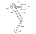
- FIG. 3A is a view showing another example of the axial configuration of the leg unit 10 (viewed from the side of the leg unit 10).
- FIG. 3B is a view schematically showing the appearance of the leg unit 10 shown in FIG. 3A as viewed from above.
- these joints 100 may be arranged such that the rotation axis of the hip joint Pitch axis 100b and the rotation axis of the knee joint Pitch axis 100c are coaxial.
- the leg unit 10 may have a closed link mechanism 106 coupled to the hip joint Pitch axis 100b and the knee joint Pitch axis 100c.
- the force output by the actuator 110b that drives the hip joint Pitch axis 100b can be transmitted to the knee joint Pitch axis 100c.
- the specific contents of the actuator 110 will be described later.
- the axial configuration of the leg unit 10 according to the present embodiment is not limited to the example described above.
- the number of axes of the leg unit 10 may be one or more arbitrary numbers (for example, one axis, ten axes, etc.).
- all serial links may be used, all parallel links may be used, or one or more serial links and one or more parallel links are mixed. It may be done.
- the leg unit 10 may have one or more underactuated joints (that is, joints not driven by the actuator 110).
- FIG. 4 is a block diagram showing an example of the functional configuration of the main unit 20.
- the main body unit 20 includes a control unit 200, a communication unit 202, a sensor unit 204, and a storage unit 206.
- Control unit 200 can be configured to include, for example, processing circuits such as a CPU and a GPU.
- the control unit 200 centrally controls the operation of the main unit 20.
- the control unit 200 controls the four leg units 10 at arbitrary timings (for example, when the robot 2 starts up) for synchronizing the timing of operation between each of the four leg units 10 in a predetermined cycle.
- the control unit 200 can cause the communication unit 202 to transmit the same synchronization signal to each of the four leg units 10 at an arbitrary timing.
- the synchronization signal may indicate a first timing sequence having a plurality of timings and the time between adjacent timings is a first cycle. Furthermore, the synchronization signal may indicate a second timing sequence having a plurality of timings and a time between adjacent timings being a second period which is a constant multiple of the first period.
- the first cycle may be 0.25 msec
- the second cycle may be 1.0 msec.
- the second timing sequence is an example of a predetermined timing sequence according to the present disclosure.
- the second cycle is an example of a predetermined cycle according to the present disclosure.
- the first timing sequence may be a plurality of timing sequences responsible for the motion of each leg unit 10.
- the second timing sequence may be a plurality of timing sequences that control the motion of the entire robot 2.
- the first timing sequence may indicate the individual timing of the start of the output of pulse width modulation (PWM) to control the supply of power to the individual actuators 110 in each leg unit 10.
- PWM pulse width modulation
- the first timing sequence may indicate individual acquisition timings of sensing results (for example, angle information of the individual actuators 110, etc.) by the respective sensor units 112 in the respective leg units 10, which will be described later.
- the second timing sequence may indicate, for example, acquisition timings of sensing results by the respective sensor units 112 in the leg unit 10, which are used for calculation (specification) of position and orientation information of each leg unit 10.
- each leg unit 10 performs the corresponding leg unit 10 at that timing based on the sensing result by each sensor unit 112 at that timing for each timing included in the second timing sequence.
- the position and orientation information of each may be sequentially calculated, and the position and orientation information may be sequentially transmitted to the main unit 20.
- the synchronization signal is a rectangular wave pulse signal as shown in FIG.
- the operation of each leg unit 10 can be synchronized by using a rise of a voltage corresponding to the synchronization signal (hereinafter referred to as a synchronization signal voltage) as a trigger.
- a synchronization signal voltage a voltage corresponding to the synchronization signal
- the motion in each leg unit 10 can be controlled as described above, triggered by the rise of the synchronization signal voltage for each timing included in the first timing sequence.
- the motion of the entire robot 2 can be controlled as described above, triggered by the rise of the synchronization signal voltage at each timing included in the second timing sequence.
- the sensing result by the sensor unit 112 in each joint 100 in each leg unit 10 is sequentially acquired every rise of the synchronization signal voltage corresponding to each timing included in the first timing sequence.
- torque output by the individual actuators 110 in each joint 100 in each leg unit 10 can be sequentially started.
- each leg unit 10 is operated by the sensor unit 112 in each joint 100 at the corresponding timing at each rise of the synchronization signal voltage corresponding to each timing included in the second timing sequence. Based on the sensing result, the position and posture of the leg unit 10 at the timing can be sequentially calculated. The specific contents of these functions will be described later.
- FIG. 5 illustrates an example in which at least one timing included in the first timing sequence matches at least one timing included in the second timing sequence.
- the present invention is not limited to such an example, and all the timings included in the first timing sequence may be different from all the timings included in the second timing sequence.
- the synchronization signal corresponding to the first timing sequence and the synchronization signal corresponding to the second timing sequence may be the same signal or may be different signals.
- the control unit 200 causes the communication unit 202 to transmit these two types of synchronization signals to each of the four leg units 10 at an arbitrary timing.
- each time position and orientation information of each of the four leg units 10 at the nearest timing indicated by the second timing sequence is received from each of the leg units 10, the control unit 200 relates to each of the four leg units 10. It is possible to cause the communication unit 202 to transmit, to the leg unit 10, operation instruction information of the leg unit 10 at the next timing indicated by the second timing sequence.
- the control unit 200 first receives the four received.
- the position and orientation information of the robot 2 (for example, the position and orientation information of the body of the robot 2) at the latest timing is specified based on the position and orientation information of each of the leg units 10 and the known kinematics algorithm.
- the control unit 200 determines the movement purpose of the robot 2 corresponding to the next timing indicated by the second timing sequence, the position and orientation information of the robot 2 at the latest timing, and the known reverse kinematics algorithm Based on the next timing, the magnitude and direction of force that the robot 2 should exert on the environment (hereinafter, “the magnitude of the target force of the robot 2” and “the target force of the robot 2 (Sometimes referred to as “direction”).
- the control unit 200 determines the force to be exerted by each of the four leg units 10 at the next timing based on the calculated magnitude of the target force of the robot 2 and the direction of the target force.
- Command value hereinafter may be referred to as “motion command value of each leg unit 10” is calculated.
- control unit 200 decomposes the magnitude of the target force of the robot 2 and the direction of the target force for each leg unit 10 according to the positional relationship of each of the four leg units 10, The magnitude of the target force of each leg unit 10 and the direction of the target force are calculated as the motion command value of each leg unit 10.
- control unit 200 generates, for each leg unit 10, operation instruction information of the leg unit 10 at the next timing that includes the calculated movement command value of the leg unit 10.
- the control unit 200 causes the communication unit 202 to transmit the operation instruction information of the leg unit 10 to the leg unit 10.
- the motion instruction information of the leg unit 10 is position information of a target of the leg unit 10 at the next timing (for example, position information of a target of a specific part (such as the toe 102 of the leg unit 10)), It may further include information indicating the posture of the target of the leg unit 10 at the next timing.
- the communication unit 202 exchanges information with each of the four leg units. For example, the communication unit 202 receives, from each of the leg units 10, position and orientation information of each of the leg units 10 at the closest timing indicated by the second timing sequence. Further, the communication unit 202 transmits, to each of the four leg units 10, operation instruction information of the leg unit 10 at the next timing indicated by the second timing sequence to the leg unit 10 according to the control of the control unit 200. Do.
- the communication unit 202 transmits / receives information to / from an external device (for example, a general-purpose PC (Personal Computer) or the like) via a predetermined network (for example, the Internet or various LANs (Local Area Network) or the like). Is also possible.
- the communication unit 202 can receive, from an external device, instruction information of the user regarding the movement purpose and operation of the robot 2.
- the sensor unit 204 performs various types of sensing on, for example, the external world and the state of the robot 2.
- the sensor unit 204 is, for example, a camera (image sensor), a depth sensor (for example, a time of flight sensor or a stereo camera), a microphone, an acceleration sensor, a gyroscope, a temperature sensor, a geomagnetic sensor, and / or a torque sensor And so on.
- the sensor unit 204 may include a receiver that receives positioning signals from positioning satellites such as GPS (Global Positioning System) and GLONASS (Global Navigation Satellite System).
- GPS Global Positioning System
- GLONASS Global Navigation Satellite System
- the storage unit 206 may be configured to include, for example, a storage device such as a hard disk drive (HDD) or a memory such as a RAM or a ROM.
- the storage unit 206 stores, for example, various data such as a map information DB, an object information DB, and a physical information DB, and various applications.
- the map information DB may be a database in which real world map information is stored.
- the object information DB may be, for example, a database in which position information of the object and attribute information (shape, assumed weight, etc.) of the object are stored for each object.
- the physical information DB may be a database in which information (for example, position, shape, size, etc.) of each part of the robot 2 is stored.
- FIG. 6 is a block diagram showing an example of a functional configuration of the leg unit 10.
- the leg unit 10 includes a plurality of joints 100, a control unit 150, a communication unit 160, a sensor unit 162, and a storage unit 164.
- the plurality of joints 100 may have, for example, at least three joints 100 such as a hip joint Roll axis 100 a, a hip joint Pitch axis 100 b, and a knee joint Pitch axis 100 c.
- the description overlapping with the above description will be omitted.
- the joint 100 includes one or more actuators 110, a sensor unit 112, and a motor driver 114.
- the motor driver 114 controls the operation of each of the one or more actuators 110 in the relevant joint 100 according to the control of the control unit 150 described later. For example, at each timing included in the first timing sequence indicated by the synchronization signal received from the main unit 20, the motor driver 114 receives the torque corresponding to the torque command value at the timing received from the control unit 150. It is output to all or part of one or more actuators 110.
- the motor driver 114 transmits the sensing result by the sensor unit 112 described later to the control unit 150. For example, at each timing included in the first timing sequence indicated by the synchronization signal, the motor driver 114 first detects the result of sensing by the sensor unit 112 at the timing (for example, one or more actuators in the corresponding joint 100). The angle information of each of 110 etc. is sequentially acquired from the sensor unit 112, and the acquired sensing result is sequentially transmitted to the control unit 150.
- Actuator 110 The actuator 110 generates power based on the energy (such as power) supplied from the energy supply port and the control signal transmitted from the motor driver 114.
- all actuators 110 included in the corresponding leg unit 10 may include a motor.
- one or more actuators 110 included in the corresponding leg unit 10 may be, for example, a pneumatic actuator, a hydraulic actuator, or a rubber actuator.
- the sensor unit 112 performs various types of sensing on each of the one or more actuators 110 in the corresponding joint 100.
- the sensor unit 112 includes an angle sensor, an acceleration sensor, and a torque sensor.
- the sensor unit 112 may sense the rotation angle of each actuator 110 in the corresponding joint 100.
- the sensor unit 112 may sense the velocity, current value, output torque, and the like of each actuator 110 in the corresponding joint 100.
- the sensor unit 162 performs various types of sensing on the state of the corresponding leg unit 10.
- the sensor unit 162 includes a contact sensor, a pressure sensor, and the like.
- the sensor unit 162 can sense the presence or absence of contact with another object at the tip of the leg unit 10 (such as the toe 102), and the magnitude of the force received from the other object at the tip.
- Control unit 150 The control unit 150 centrally controls the operation of the leg unit 10.
- the control unit 150 determines, based on the sensing results of each of the plurality of joints 100 at the timing, at each timing included in the second timing sequence indicated by the synchronization signal. In addition, it is possible to cause the communication unit 160 to sequentially transmit its own position and orientation information at the timing to the main body unit 20. As an example, at each timing included in the second timing sequence, the control unit 150 causes a sensing result by the sensor unit 112 at the relevant timing of each of the plurality of joints 100 and a sensing result by the sensor unit 162 at the relevant timing. The position and orientation information of the user at the timing is specified based on the above, and the specified position and orientation information is sequentially transmitted to the communication unit 160 to the main body unit 20.
- the control unit 150 first causes the sensor unit 112 in each joint 100 at the timing to obtain a sensing result regarding the posture of the joint 100. (For example, angle information of each actuator 110 in the joint 100 or the like) is acquired from each sensor unit 112, and a sensing result by the sensor unit 162 at the timing is acquired from the sensor unit 162. Next, based on these sensing results and a known kinematics algorithm, the control unit 150 determines the position and posture of the leg unit 10 at the corresponding timing (that is, the position and posture of the corresponding leg unit 10). Identify (calculate).
- control unit 150 may use position coordinates of the center of gravity of the leg unit 10 at the timing, and / or position information of a specific part (for example, the toe 102) at the timing, of the leg unit 10 at the timing. Identify as a location. Then, the control unit 150 causes the communication unit 160 to transmit position and orientation information indicating the specified position and orientation of the leg unit 10 to the main unit 20.
- the position and orientation information of the leg unit 10 may further include information of types other than the position and orientation of the leg unit 10 at the timing.
- the position and orientation information of the leg unit 10 may further include the measurement result of the magnitude of the force received by the leg unit 10 from the environment at the timing and the measurement result of the direction of the force.
- the position and orientation information of the leg unit 10 is the measurement result of the angle, velocity, current value, and / or torque of the individual actuators 110 in the leg unit 10 at the timing. May be further included.
- each time operation instruction information (corresponding to the leg unit 10) is received from the main unit 20, the control unit 150 performs the operation instruction information based on the operation instruction information and the received synchronization signal. Operation of each of the plurality of joints 100 at a timing corresponding to. For example, each time the operation instruction information is received from the main body unit 20, the control unit 150 causes the newly received operation instruction information of the plurality of timings included in the second timing sequence indicated by the synchronization signal. At timings corresponding to, the operations of the individual actuators 110 included in each of the plurality of joints 100 are sequentially controlled based on the operation instruction information.
- the timing corresponding to the operation instruction information is, for example, an order corresponding to the cumulative number of receptions of the operation instruction information among a plurality of timings included in the second timing sequence indicated by the received synchronization signal.
- the timing may be (for example, in the same order as the cumulative number of receptions of the operation instruction information, etc.).
- control unit 150 first forces each of all joints 100 in leg unit 10 to exert at a timing corresponding to the operation instruction information.
- Command value (hereinafter may be referred to as “motion command value of each joint 100”) is calculated based on the motion command value of the leg unit 10 indicated by the motion command information.
- the control unit 150 corresponds to the operation instruction information by performing a force control calculation on each of all the joints 100 in the leg unit 10 based on the calculated movement command value of the joint 100.
- an output command value of torque to be output by the joint 100 is calculated.
- control unit 150 causes the actuator 110 in the joint 100 to output a torque corresponding to the calculated torque output command value of the actuator 110 for each of all the joints 100 in the leg unit 10,
- the instruction information is transmitted to the motor driver 114 in the joint 100.
- the instruction information may include a torque output command value of each actuator 110 in the joint 100.
- the communication unit 160 exchanges information with the main unit 20.
- the communication unit 160 receives the synchronization signal and the operation instruction information from the main body unit 20.
- the communication unit 160 controls the control unit 150 of the position and orientation information of the corresponding leg unit 10 at the latest timing specified based on the sensing result at the latest timing indicated by the second timing sequence. It transmits to main part 20 according to.
- the communication unit 160 can also transmit and receive information with other leg units 10.
- the storage unit 164 may be configured to include, for example, a memory such as a RAM or a ROM, or a storage device such as an HDD.
- the storage unit 164 stores various data and various applications.
- the storage unit 164 may output unique information of the corresponding leg unit 10 (for example, the mass property of the leg unit 10, the length of each link of the leg unit 10, the movable range of the leg unit 10, and the leg unit 10). And the maximum torque value that the leg unit 10 can output.
- the control unit 150 performs the force control calculation of each joint 100, the control unit 150 can be used by reading out the specific information of the corresponding leg unit 10 from the storage unit 164. Therefore, since it becomes unnecessary for the leg unit 10 to receive the specific information on the corresponding leg unit 10 from the main body 20, the amount of information transmitted and received between the leg unit 10 and the main body 20 in real time can be suppressed.
- the functional configuration of the leg unit 10 according to the present embodiment is not limited to the example described above.
- the control unit 150 may have all or part of the functions of the motor driver 114 in each of the joints 100 described above.
- the motor driver 114 may not necessarily be disposed in each joint 100.
- the motor driver 114 in each joint 100 may have a part of the functions of the control unit 150 described above.
- the control unit 150 controls the operation of each of the plurality of joints 100 at the timing corresponding to the operation instruction information based on the operation instruction information and the synchronization signal received from the main body unit 20.
- the motor driver 114 in each joint 100 sets the timing of the individual actuators 110 in the joint 100 at the timing corresponding to the operation instruction information based on the operation instruction information and the synchronization signal. The operation may be controlled directly.
- FIG. 7 is a flowchart showing the flow of processing of the main unit 20 according to the present embodiment.
- the control unit 200 of the main body unit 20 performs initial setting on various functions (such as an application) mounted on the main body unit 20 (for example) S101).
- the communication unit 202 transmits the synchronization signal to each of the four leg units 10 according to the control of the control unit 200 (S103).
- the control unit 200 causes the current timing to be next to the previous timing among the plurality of timings included in the second timing sequence (that is, the timing sequence that controls the motion of the entire robot 2) indicated by the synchronization signal. It is determined whether the time has arrived. Note that for the first time, the control unit 200 determines whether the current time has reached the first timing included in the second timing sequence (S105). While the current time has not reached the corresponding timing (hereinafter, also referred to as “I-th timing”) (S105: No), the control unit 200 repeats the processing of S105 again.
- the main body unit 20 receives the position and orientation information of the leg unit 10 at the I-th timing from each of the four leg units 10. To do (S107).
- control unit 200 of the main body unit 20 controls the robot at the I-th timing based on the received position and orientation information of each of the four leg units 10 at the I-th timing and the known kinematics algorithm.
- the position and posture of the torso 2 are calculated (S109).
- control unit 200 determines the motion purpose of the robot 2 corresponding to the (I + 1) th timing indicated by the second timing sequence, the position and orientation information of the robot 2 specified in S109, and the known reverse kinematics algorithm And the known inverse dynamics algorithm, the magnitude of the force that the robot 2 should exert on the environment at the (I + 1) th timing (the magnitude of the target force) and the direction of the force (target force) Direction) is calculated (S111).
- control unit 200 decomposes the magnitude of the target force of the robot 2 and the direction of the target force for each of the leg units 10, so that each of the four leg units 10 is at the I + 1th timing.
- the command value ie, the motion command value of each leg unit 10) regarding the force to be exerted is calculated (S113).
- the communication unit 202 transmits, to each of the four leg units 10, operation instruction information at the (I + 1) th timing including the exercise command value of the leg unit 10 to the corresponding leg unit 10 according to the control of the control unit 200. (S115). After that, the control unit 200 repeats the processing after S105.
- FIG. 8 is a flowchart showing a part of the process flow of the leg unit 10 according to the present embodiment. Note that the processing flow of each of the four leg units 10 may be all the same. Hereinafter, for convenience of explanation, the flow of processing of one leg unit 10 will be described.
- the control unit 150 of the leg unit 10 first performs initial setting on various functions (such as an application) mounted on the leg unit 10, for example ( S201).
- the leg unit 10 receives the synchronization signal from the main unit 20 (S203).
- the control unit 150 of the leg unit 10 follows the previous one of the plurality of timings included in the second timing sequence indicated by the synchronization signal (that is, the timing sequence that controls the motion of the entire robot 2). It is determined whether the current time has arrived at the timing of. Note that for the first time, the control unit 150 determines whether the current time has reached the first timing included in the second timing sequence (S205).
- the control unit 150 determines the first timing sequence (that is, the synchronization signal indicates). It is determined whether the current time has reached the timing next to the previous timing among the plurality of timings included in the timing sequence that controls the movement of each leg unit 10). Note that for the first time, the control unit 150 determines whether the current time has reached the first timing included in the first timing sequence (S207). While the current time has not reached the corresponding timing (hereinafter, also referred to as “Jth timing”) (S207: No), the control unit 150 repeats the processing after S205 again.
- the sensor unit 112 in each joint 100 included in the leg unit 10 is, for example, the angle of each actuator 110 in the joint 100, etc.
- To And control part 150 acquires a sensing result by sensor part 112 in each joint 100 from each sensor part 112 (S209).
- the control unit 150 performs force control based on the sensing result (for example, angle information of the individual actuators 110 in the joint 100) acquired in S209 for each of all the joints 100 in the leg unit 10. Perform an operation. For example, when S227 described later has been executed at least once, the control unit 150 determines the motion command value of each joint 100 calculated in the most recent S227 and the sensing result acquired in S209. Force control calculation is performed on each of all the joints 100 in the leg unit 10 (S211).
- control unit 150 calculates an output command value of torque to be output by the joint 100 based on the calculation result in S211 (S213).
- control unit 150 causes the actuator 110 in the joint 100 to output a torque corresponding to the torque output command value of the joint 100 calculated in S213 for each of all the joints 100 in the leg unit 10. Then, the actuator 110 is controlled (S215). After that, the control unit 150 repeats the processing after S205 again.
- the leg unit 10 performs the same processing as S209 described above (S217).
- the control unit 150 determines the sensing result at the I-th timing acquired in S217 (for example, angle information of the individual actuators 110 included in each of the plurality of joints 100).
- the position and posture of the leg unit 10 at the I-th timing are specified (calculated) on the basis of and the known kinematics algorithm (S221).
- control unit 150 causes the communication unit 160 to transmit position and orientation information indicating the position and orientation of the leg unit 10 at the I-th timing specified in S221 (S223).
- the leg unit 10 receives the operation instruction information corresponding to the (I + 1) th timing from the main body unit 20 (S225).
- control unit 150 causes each of all the joints 100 in the leg unit 10 to perform at the (I + 1) th timing based on the motion command value of the leg unit 10 itself indicated by the motion instruction information received in S225.
- the command value related to the power to be calculated (that is, the motion command value of each joint 100) is calculated (S227).
- leg unit 10 performs the processing of S211 and the above.
- the above-described processing of S221 to S227 may be repeatedly performed every second cycle.
- the leg unit 10 is based on the sensing result of each of the plurality of joints 100 at the nearest timing among the plurality of timings included in the second timing sequence.
- the position and orientation information of the leg unit 10 at the timing is transmitted to the main body unit 20, and the operation instruction information of the leg unit 10 at the next timing of the timing is based on the position and orientation information of the leg unit 10 at the timing. 20, and controls the operation of each of the plurality of joints 100 based on the operation instruction information. Therefore, the processing load on the main body 20 when controlling the operation of each joint 100 can be reduced.
- the main body unit 20 can control the movement of each leg in units of 10 leg units instead of 110 units as in the comparative example of the present disclosure. Then, the control unit 150 of the leg unit 10 can control the operation of the individual actuators 110 included in each of all the joints 100 included in the corresponding leg unit 10. As described above, according to the present embodiment, the operation of each of the plurality of joints 100 included in each leg unit 10 can be decentralized and controlled by the main body 20 and the leg unit 10.
- the main body unit 20 merely designates (as the operation instruction information) the position information of the target of the toe 102 of each leg unit 10 at the next timing, the individual joints 100 included in each leg unit 10 The angle of the target at the next timing can be calculated by each leg unit 10. Therefore, the calculation load of the main body unit 20 can be reduced.
- a method may be considered in which the operation timings of the four leg units 10 are matched as much as possible by using only existing feedback control without using a synchronization signal. Specifically, in this method, it is possible to partially cover (compensate) the time lag among the four leg units 10 by controlling the phase fluctuation due to the time lag in the direction of the amplitude. However, in this method, it is difficult to increase the control gain, so the control performance may be reduced compared to the present embodiment. In other words, according to the present embodiment, the control performance of the robot 2 can be improved by using the synchronization signal.
- each leg unit 10 can be configured to be removable with respect to the main body 20. Therefore, for example, when at least one leg unit 10 malfunctions while the robot 2 is in operation, each of the at least one leg unit 10 is easily replaced with another leg unit 10 whose operation has been confirmed. It can be exchanged. Therefore, the stop time of the robot 2 due to the malfunction of the leg unit 10 can be shortened, for example, as compared with the present comparative example.
- operation confirmation and repair can be performed by the leg unit 10 alone without stopping the operation of the main unit 20. Is high. Furthermore, at the time of development of the robot 2, it is also possible to perform the assembly of the leg unit 10 and the assembly of the main body 20 in parallel. Thereby, the lead time of manufacture of robot 2 can be shortened compared with this comparative example, for example.
- connection method between the main body 20 and each leg unit 10 can be unified. Therefore, the degree of freedom in design can be further improved, so that the number of leg portions (leg units 10) can be selected with a higher degree of freedom at the time of design of the robot 2 as compared with this comparative example.
- the axis configuration is a serial link arm having 7 degrees of freedom, and, for example, one or more arm units attached to the tip of the serial link arm, such as a gripper or a robot hand, instead of the leg unit 10 It may be attached to the main body 20.
- the robot 2 having the gripping arm unit capable of gripping and operating one or more objects.
- the arm unit is an example of a limb unit according to the present disclosure.
- one or more arm units having a shaft configuration of 7 degrees of freedom serial link arm and, for example, a camera, a laser scanner, etc. attached to the tip of the serial link arm are substituted for the leg unit 10 It may be attached to the main body 20.
- the robot 2 having the recognition arm unit for recognizing the surrounding environment of the robot 2 can be configured.
- the arm unit is an example of a limb unit according to the present disclosure.
- each step in each process flow described above may not necessarily be processed in the order described.
- each step may be processed in an appropriate order.
- each step may be processed partially in parallel or individually instead of being processed chronologically.
- some of the described steps may be omitted or additional steps may be added.
- the robot according to the present disclosure is not necessarily limited to a product called "robot".
- the robot according to the present disclosure is a machine (device) or other common mobile device that has one or more limb units and a main body 20, and can operate using electrical and / or magnetic action. I hope there is.
- the robot may be a vehicle, various industrial machines, or a toy.
- a control unit that causes the transmitting unit to transmit its own position and orientation information at the first timing based on the sensing result at the first timing of each of the plurality of joints;
- a receiving unit that receives, from the main unit, operation instruction information at a second timing after the first timing based on the position and orientation information of the first timing; Equipped with The limb unit, wherein the control unit controls an operation of each of the plurality of joints at the second timing based on operation instruction information at the second timing.
- the receiving unit further receives, from the main unit, a synchronization signal for synchronizing operation timing between the limb unit and one or more other limb units at a predetermined cycle.
- the synchronization signal is identical to the synchronization signal transmitted from the body to each of the one or more other limb units,
- the limb unit according to (1) wherein the control unit further controls an operation of each of the plurality of joints at the second timing based on the synchronization signal.
- (3) Further comprising the plurality of joints, Each of the plurality of joints has one or more actuators, The control unit controls the operation of each of the one or more actuators included in each of the plurality of joints at the second timing based on the operation instruction information at the second timing and the synchronization signal.
- the limb unit according to (2).
- the limb unit according to (3) wherein the position and orientation information of the user at the first timing is information specified based on a sensing result of each of the plurality of joints at the first timing.
- the synchronization signal indicates a predetermined timing sequence including a plurality of timings and the time between adjacent timings is the predetermined period, The first timing is any one of the plurality of timings included in the predetermined timing sequence, The limb unit according to (4), wherein the second timing is a timing next to the first timing among the plurality of timings included in the predetermined timing sequence.
- the control unit transmits, to the main unit, the position and orientation information at the timing based on the sensing result of each of the plurality of joints at the timing at each timing included in the predetermined timing sequence.
- the control unit causes the plurality of joints at any timing included in the predetermined timing sequence corresponding to the newly received operation instruction information.
- the timing corresponding to the newly received operation instruction information is the timing of an order corresponding to the cumulative number of receptions of the operation instruction information among the plurality of timings included in the predetermined timing sequence.
- the control unit calculates a command value related to an output torque of each of the plurality of joints at the second timing based on operation instruction information at the second timing, and The limb unit according to (8), wherein each of the one or more actuators included in each of the plurality of joints is controlled based on a command value related to an output torque of the joint. (10) Each time operation instruction information is received from the main unit, the control unit is configured to control the plurality of joints at any one of timings included in the predetermined timing sequence, corresponding to the newly received operation instruction information.
- the command value for each output torque is sequentially calculated based on the operation instruction information, and The limb unit according to (9), wherein each of the one or more actuators included in each of the plurality of joints is sequentially controlled based on a command value related to an output torque of the joint.
- the sensing result of each of the plurality of joints at the first timing includes the sensing result of the posture of each of the plurality of joints at the first timing, any one of the above (5) to (10) Limb unit as described in.
- the control unit sequentially specifies, at each timing included in the predetermined timing sequence, position / posture information of itself at the timing based on a sensing result at each timing of each of the plurality of joints.
- the limb unit according to any one of (12) to (12).
- the position and orientation information of the limb unit at the first timing, and the position and orientation information of the other limb unit at the first timing received by the main body from each of the one or more other limb units
- the limb unit according to any one of (5) to (13), wherein the operation instruction information at the second timing is determined by the main body based on the second timing.
- the transmission unit The limb unit according to any one of (11) to (14), further comprising: a sensor unit that senses the posture of each of the plurality of joints.
- a sensor unit that senses the posture of each of the plurality of joints.
- a control unit configured to transmit, to the main unit, the position and orientation information of the limb unit at the first timing based on the sensing result at the first timing of each of a plurality of joints included in the limb unit;
- a receiving unit that receives, from the main body, operation instruction information of the limb unit at a second timing after the first timing based on position and orientation information of the limb unit at the first timing; Have The control unit controls an operation of each of a plurality of joints of the limb unit at the second timing based on motion instruction information of the limb unit at the second timing.
- the main unit transmits, to each of the plurality of limb units, a synchronization signal for synchronizing the timing of operation between each of the plurality of limb units at a predetermined cycle.
- the synchronization signals sent to each of the plurality of limb units are all identical,
- Each of a plurality of joints included in each of the plurality of limb units has one or more actuators,
- the receiving unit of each of the plurality of limb units further receives the synchronization signal from the body unit,
- the control unit of each of the plurality of limb units is configured of the plurality of joints of the limb unit at the second timing based on the operation instruction information of the limb unit at the second timing and the synchronization signal.
- the synchronization signal indicates a predetermined timing sequence including a plurality of timings and the time between adjacent timings is the predetermined period,
- the first timing is any one of the plurality of timings included in the predetermined timing sequence,
- the main body specifies position and orientation information of the robot at the first timing based on position and orientation information of the limb unit at the first timing received from each of the plurality of limb units, and , The operation instruction information of each of the plurality of limb units at the second timing is determined based on position and orientation information of the robot at the first timing and an exercise purpose of the robot at the second timing.
- the robot according to (18).
- the control unit of each of the plurality of limb units is, for each timing included in the predetermined timing sequence, position and orientation information of the limb unit at the timing based on the sensing result at each of the plurality of joints.
- the control unit of each of the plurality of limb units is included in the predetermined timing sequence corresponding to the newly received operation instruction information each time the operation instruction information is received from the main body unit.
Landscapes
- Engineering & Computer Science (AREA)
- Robotics (AREA)
- Mechanical Engineering (AREA)
- Manipulator (AREA)
Abstract
Description
本開示は、肢ユニット、および、ロボットに関する。 The present disclosure relates to a limb unit and a robot.
従来、例えば4脚ロボットや2脚ロボットなどの、一以上の脚部を有するロボットが各種開発されている。 Conventionally, various robots having one or more legs, such as a four-legged robot and a two-legged robot, have been developed.
例えば、下記特許文献1には、4個の脚モジュールがそれぞれ関節を介して胴体部に取り付けられた4脚ロボットが開示されている。各脚モジュールは、当該胴体部に設けられた関節用モータによって前後に回動される。 For example, Patent Document 1 below discloses a four-legged robot in which four leg modules are respectively attached to a body via joints. Each leg module is pivoted back and forth by an articulation motor provided on the body.
しかしながら、特許文献1に記載の技術では、各脚モジュールの動作を制御する際の4脚ロボット本体の処理負荷が大きい。例えば、特許文献1に記載の技術では、各脚モジュールの動作を制御するために、4脚ロボット本体は、胴体部に設けられている当該脚モジュールに対応する関節用モータを直接制御しなければならない。 However, in the technology described in Patent Document 1, the processing load of the four-legged robot main body when controlling the operation of each leg module is large. For example, in the technology described in Patent Document 1, in order to control the operation of each leg module, the four-legged robot main body has to directly control the joint motor corresponding to the leg module provided in the body part. It does not.
そこで、本開示では、個々の関節の動作を制御する際の本体部の処理負荷を軽減することが可能な、新規かつ改良された肢ユニット、および、ロボットを提案する。 Thus, the present disclosure proposes a novel and improved limb unit and robot that can reduce the processing load on the main body when controlling the motion of individual joints.
本開示によれば、複数の関節の各々の第1のタイミングにおけるセンシング結果に基づいた、前記第1のタイミングにおける自己の位置姿勢情報を本体部へ送信部に送信させる制御部と、前記第1のタイミングにおける自己の位置姿勢情報に基づいた、前記第1のタイミングよりも後の第2のタイミングにおける動作指示情報を前記本体部から受信する受信部と、を備え、前記制御部は、前記第2のタイミングにおける動作指示情報に基づいて、前記第2のタイミングにおける前記複数の関節の各々の動作を制御する、肢ユニットが提供される。 According to the present disclosure, there is provided a control unit which causes the transmitting unit to transmit its own position and orientation information at the first timing to the main body based on the sensing result at the first timing of each of the plurality of joints. A receiving unit for receiving, from the main unit, operation instruction information at a second timing after the first timing based on position and orientation information of one's own at the timing of A limb unit is provided that controls the motion of each of the plurality of joints at the second timing based on motion instruction information at the second timing.
また、本開示によれば、複数の肢ユニット、および、本体部を備え、前記複数の肢ユニットの各々は、複数の関節と、当該肢ユニットが有する複数の関節の各々の第1のタイミングにおけるセンシング結果に基づいた、前記第1のタイミングにおける当該肢ユニットの位置姿勢情報を前記本体部へ送信部に送信させる制御部と、前記第1のタイミングにおける当該肢ユニットの位置姿勢情報に基づいた、前記第1のタイミングよりも後の第2のタイミングにおける当該肢ユニットの動作指示情報を前記本体部から受信する受信部と、を有し、前記制御部は、前記第2のタイミングにおける当該肢ユニットの動作指示情報に基づいて、前記第2のタイミングにおける、当該肢ユニットが有する複数の関節の各々の動作を制御する、ロボットが提供される。 Further, according to the present disclosure, a plurality of limb units and a body portion are provided, and each of the plurality of limb units includes a plurality of joints and a first timing of each of the plurality of joints included in the limb unit. A control unit that causes the transmitting unit to transmit position and orientation information of the limb unit at the first timing to the main unit based on a sensing result, and position and orientation information of the limb unit at the first timing, A receiving unit that receives, from the main body unit, operation instruction information of the limb unit at a second timing later than the first timing, and the control unit determines the limb unit at the second timing The robot controls the motion of each of the joints of the limb unit at the second timing based on the motion instruction information of It is subjected.
以上説明したように本開示によれば、個々の関節の動作を制御する際の本体部の処理負荷を軽減することができる。なお、ここに記載された効果は必ずしも限定されるものではなく、本開示中に記載されたいずれかの効果であってもよい。 As described above, according to the present disclosure, it is possible to reduce the processing load on the main body when controlling the operation of each joint. In addition, the effect described here is not necessarily limited, and may be any effect described in the present disclosure.
以下に添付図面を参照しながら、本開示の好適な実施の形態について詳細に説明する。なお、本明細書及び図面において、実質的に同一の機能構成を有する構成要素については、同一の符号を付することにより重複説明を省略する。 Hereinafter, preferred embodiments of the present disclosure will be described in detail with reference to the accompanying drawings. In the present specification and the drawings, components having substantially the same functional configuration will be assigned the same reference numerals and redundant description will be omitted.
また、本明細書及び図面において、実質的に同一の機能構成を有する複数の構成要素を、同一の符号の後に異なるアルファベットを付して区別する場合もある。例えば、実質的に同一の機能構成を有する複数の構成要素を、必要に応じて脚ユニット10aおよび脚ユニット10bのように区別する。ただし、実質的に同一の機能構成を有する複数の構成要素の各々を特に区別する必要がない場合、同一符号のみを付する。例えば、脚ユニット10aおよび脚ユニット10bを特に区別する必要が無い場合には、単に脚ユニット10と称する。
Further, in the present specification and the drawings, a plurality of components having substantially the same functional configuration may be distinguished by attaching different alphabets to the same reference numerals. For example, a plurality of components having substantially the same functional configuration are distinguished as the
また、以下に示す項目順序に従って当該「発明を実施するための形態」を説明する。
1.比較例
2.実施形態の詳細な説明
3.変形例
In addition, the “mode for carrying out the invention” will be described in the order of items shown below.
1. Comparative example 2. Detailed Description of Embodiments 3. Modified example
<<1.比較例>>
本開示は、一例として「2.実施形態の詳細な説明」において詳細に説明するように、多様な形態で実施され得る。最初に、本開示に係る実施形態の特徴を明確に示すために、本開示の比較例について説明する。
<< 1. Comparative example >>
The present disclosure can be implemented in various forms, as described in detail in “2. Detailed Description of the Embodiments” as an example. First, to clearly show the features of the embodiments according to the present disclosure, comparative examples of the present disclosure will be described.
<1-1.構成>
まず、本比較例に係るロボット90の構成について説明する。ロボット90は、4脚ロボットである。ロボット90は、胴体部900および4本の脚部902を有する。
<1-1. Configuration>
First, the configuration of the robot 90 according to the present comparative example will be described. The robot 90 is a four-legged robot. The robot 90 has a body 900 and four legs 902.
胴体部900は、制御部904を含む。制御部904は、例えばCPU(Central Processing Unit)やGPU(Graphical Processing Unit)などの処理回路を含む。制御部904は、ロボット90の動作を統括的に制御する。例えば、制御部904は、4本の脚部902の各々に配置されている個々のアクチュエータの動作を制御する。 The torso unit 900 includes a control unit 904. The control unit 904 includes a processing circuit such as, for example, a central processing unit (CPU) or a graphical processing unit (GPU). The control unit 904 generally controls the operation of the robot 90. For example, the control unit 904 controls the operation of an individual actuator disposed in each of the four legs 902.
4本の脚部902の各々は、複数の関節と複数のリンクとを含むリンク機構としてそれぞれ構成されている。例えば、当該複数の関節は、胴体部900に接続する股関節、膝関節、および、足首関節などを含む。また、当該複数のリンクは、足裏を含み、かつ、足首関節に接続する第1リンク、足首関節と膝関節とを連結する第2リンク、および、膝関節と股関節とを連結する第3リンクなどを含む。 Each of the four legs 902 is configured as a link mechanism including a plurality of joints and a plurality of links. For example, the plurality of joints include a hip joint connected to the trunk 900, a knee joint, an ankle joint, and the like. In addition, the plurality of links include a sole and a first link connecting to the ankle joint, a second link connecting the ankle joint and the knee joint, and a third link connecting the knee joint and the hip joint And so on.
当該複数の関節の各々は、例えば当該関節の回転軸回りに当該関節を回転させる力を出力可能な一以上のアクチュエータを有する。 Each of the plurality of joints has, for example, one or more actuators capable of outputting a force for rotating the joint around the rotation axis of the joint.
<1-2.処理の流れ>
次に、図10を参照して、本比較例に係る処理の流れについて説明する。以下では、ロボット90が、4本の脚部902の各々に配置されている関節ごとの制御演算を第1の周期(例えば0.25msecなど)で繰り返して行うものとする。また、ロボット90は、運動目的に応じたロボット90の動作の計算(例えば、ロボット90が環境に対して発揮すべき力の計算など)を第2の周期(例えば1.0msecなど)で繰り返して行うものとする。
<1-2. Flow of processing>
Next, the flow of processing according to the present comparative example will be described with reference to FIG. In the following, it is assumed that the robot 90 repeatedly performs control calculation for each joint disposed in each of the four legs 902 in a first cycle (for example, 0.25 msec). Also, the robot 90 repeats calculation of the motion of the robot 90 according to the purpose of movement (for example, calculation of force to be exerted on the environment by the robot 90) in a second cycle (for example, 1.0 msec) Assumed to be performed.
図10に示したように、まず、例えばロボット90の起動時などに、ロボット90の制御部904は、例えばロボット90に実装されている各種の機能(アプリケーションなど)に関する初期設定を行う(S901)。 As shown in FIG. 10, first, for example, at the time of activation of the robot 90, the control unit 904 of the robot 90 performs initial setting regarding various functions (applications etc.) mounted on the robot 90, for example (S901) .
その後、制御部904は、以下で説明するS903~S913の処理を第1の周期で繰り返す。具体的には、まず、制御部904は、4本の脚部902の各々に配置されている個々のアクチュエータの角度情報の前回のセンシング時から、当該第1の周期に対応する時間が経過したか否かを判定する(S903)。当該第1の周期に対応する時間が前回のセンシング時から未経過である間は(S903:No)、制御部904は、S903の処理を繰り返す。 Thereafter, the control unit 904 repeats the processing of S903 to S913 described below in a first cycle. Specifically, first, the control unit 904 determines that the time corresponding to the first period has elapsed since the previous sensing of the angle information of the individual actuators arranged in each of the four legs 902. It is determined whether or not (S903). While the time corresponding to the first cycle is not yet elapsed from the previous sensing (S903: No), the control unit 904 repeats the process of S903.
一方、当該第1の周期に対応する時間が前回のセンシング時から経過した際には(S903:Yes)、4本の脚部902の各々の各関節に配置されているセンサ部は、各関節内に配置されている個々のアクチュエータの角度をセンシングする。例えば、各関節内に配置されているセンサ部は、当該関節内の個々のアクチュエータに関して、前回のセンシング時からの当該アクチュエータの角度の変位量をセンシングする。 On the other hand, when the time corresponding to the first cycle has elapsed since the previous sensing (S903: Yes), the sensor units disposed at each joint of each of the four legs 902 are each joint It senses the angles of the individual actuators located inside. For example, the sensor unit disposed in each joint senses the displacement amount of the angle of the actuator from the previous sensing with respect to each actuator in the joint.
そして、制御部904は、各センサ部によるセンシング結果を各センサ部から取得する(S905)。 And the control part 904 acquires the sensing result by each sensor part from each sensor part (S905).
続いて、制御部904は、ロボット90全身の動作の前回の計算時から、当該第2の周期に対応する時間が経過したか否かを判定する(S907)。当該第2の周期に対応する時間が、ロボット90の動作の前回の計算時から未経過である間は(S907:No)、制御部904は、まず、4本の脚部902の各々に含まれる関節ごとに、S905のセンシング結果を用いて、当該関節に関する力制御演算を行う(S909)。 Subsequently, the control unit 904 determines whether or not the time corresponding to the second cycle has elapsed since the previous calculation of the motion of the robot 90 whole body (S 907). While the time corresponding to the second cycle is not yet elapsed from the time of the previous calculation of the motion of the robot 90 (S 907: No), the control unit 904 is first included in each of the four legs 902 The force control calculation regarding the said joint is performed using the sensing result of S905 for every joint (S909).
続いて、制御部904は、各関節に配置されている個々のアクチュエータによるトルク出力指令値を、S909の演算結果に基づいて計算する。例えば、後述するS919が少なくとも一回実行済みである場合には、制御部150は、S919で計算された、当該関節に出力させる目標のトルクの値と、直近のS905で取得されたセンシング結果とに基づいて、当該脚ユニット10内の全ての関節の各々に配置されている個々のアクチュエータによるトルク出力指令値を計算する(S911)。
Subsequently, the control unit 904 calculates a torque output command value by each of the actuators disposed at each joint based on the calculation result of S909. For example, when S919 described later has been executed at least once, the
その後、制御部904は、各関節に配置されている個々のアクチュエータに対して、S911で計算された、当該アクチュエータのトルク出力指令値に対応するトルクを当該アクチュエータに出力させるように当該アクチュエータを制御する(S913)。そして、制御部904は、再びS903以降の処理を繰り返す。 After that, the control unit 904 controls the actuator so that the actuator corresponding to the torque output command value of the actuator calculated at S911 is output to the actuator arranged for each joint. (S913). Then, the control unit 904 repeats the processing after S903.
一方、S907において、当該第2の周期に対応する時間が、ロボット90の動作の前回の計算時から経過した際には(S907:Yes)、制御部904は、直近のS905で取得された、4本の脚部902の各々に配置されている個々のアクチュエータの角度のセンシング結果と、公知の運動学のアルゴリズムとに基づいて、直近のS905時点の、4本の脚部902の各々に含まれる各関節の位置および姿勢を計算する(S915)。 On the other hand, when the time corresponding to the second cycle has elapsed from the time of the previous calculation of the operation of the robot 90 in S907 (S907: Yes), the control unit 904 is acquired in the most recent S905, Included in each of the four legs 902 at the most recent time S905, based on the sensing results of the angles of the individual actuators located on each of the four legs 902, and the known kinematics algorithm. Position and posture of each joint to be calculated (S915).
続いて、制御部904は、現在の運動目的に応じて、公知の逆運動学のアルゴリズムおよび公知の逆動力学のアルゴリズムを用いて、直近のS905時点から第2の周期の時間に対応する時間の経過時においてロボット90が環境に対して発揮すべき力の大きさを計算(決定)する(S917)。 Subsequently, the control unit 904 uses the known inverse kinematics algorithm and the known inverse dynamics algorithm according to the current exercise purpose to set the time corresponding to the time of the second cycle from the most recent time S905. At the time of (e), the magnitude of the force to be exerted on the environment by the robot 90 is calculated (determined) (S917).
続いて、制御部904は、4本の脚部902の各々に含まれる関節ごとに(より詳細には、各関節内のアクチュエータごとに)、S917で計算された力の大きさを分解することにより、直近のS905時点から第2の周期の時間に対応する時間の経過時において当該関節に出力させる目標のトルクの値をそれぞれ計算する(S919)。その後、制御部904は、上記のS911以降の処理を行う。 Subsequently, for each joint included in each of the four legs 902 (more specifically, for each actuator in each joint), the control unit 904 decomposes the magnitude of the force calculated in S917. Thus, the value of the target torque to be output to the joint is calculated at the elapse of the time corresponding to the time of the second cycle from the most recent time S905 (S919). Thereafter, the control unit 904 performs the processing of the above-described S911 and thereafter.
<1-3.課題の整理>
前述したように、本比較例では、胴体部900が単独で、4本の脚部902の各々に含まれる個々のアクチュエータのトルク指令値を全て計算し、かつ、当該トルク指令値に基づいて個々のアクチュエータの動作を制御する。つまり、ロボット90は、4本の脚部902の各々の動作を集中的に制御する。このため、4本の脚部902の各々に含まれる個々の関節の動作を制御する際の、胴体部900(つまり、ロボット90の本体)の処理負荷が大きい。
<1-3. Organize issues>
As described above, in the present comparative example, the torso portion 900 alone is used to calculate the torque command values of the individual actuators included in each of the four legs 902, and individually based on the torque command values. Control the operation of the actuator. That is, the robot 90 centrally controls the operation of each of the four legs 902. For this reason, the processing load of the body 900 (that is, the main body of the robot 90) in controlling the movement of each joint included in each of the four legs 902 is large.
また、本比較例では、胴体部900と4本の脚部902とが一体的に構成されているので、ロボット90のメンテナンスの負荷が大きい。例えば、胴体部900と、4本の脚部902の各々との間では、多数のケーブルが複雑に配線されている。例えば、胴体部900と、個々の脚部902内の個々のアクチュエータとはそれぞれ別々のケーブルで直接連結されている。つまり、配線が複雑、かつ、膨大であり得る。このため、例えば4本の脚部902のうちのいずれかが故障した場合など、いずれかの脚部902を交換する際には、該当の脚部902内の一以上のケーブルだけでなく、胴体部900の内部の、該当の脚部902に連結している一以上のケーブルも適切に外す必要がある。従って、作業の負荷が大きい。 Further, in the present comparative example, since the body portion 900 and the four leg portions 902 are integrally configured, the maintenance load on the robot 90 is large. For example, a large number of cables are intricately wired between the body 900 and each of the four legs 902. For example, the body 900 and the individual actuators in the individual legs 902 are directly connected by separate cables. That is, the wiring can be complicated and enormous. For this reason, when replacing any one of the legs 902, for example, if any of the four legs 902 fail, not only one or more cables in the corresponding leg 902 but also the trunk It is also necessary to properly remove one or more cables connected to the corresponding leg 902 inside the part 900. Therefore, the work load is heavy.
そこで、上記事情を一着眼点にして、本開示の実施形態に係るロボット2を創作するに至った。本実施形態に係るロボット2は、複数の脚ユニット10、および、本体部20を備える。そして、当該複数の脚ユニット10の各々は、複数の関節100を有し、かつ、当該複数の関節100の各々の第1のタイミングにおけるセンシング結果に基づいた、当該第1のタイミングにおける当該脚ユニット10の位置姿勢情報を本体部20へ送信し、当該第1のタイミングにおける当該脚ユニット10の位置姿勢情報に基づいた、当該第1のタイミングよりも後の第2のタイミングにおける動作指示情報を本体部20から受信し、そして、当該第2のタイミングにおける動作指示情報に基づいて、当該第2のタイミングにおける当該複数の関節100の各々の動作を制御する。このため、個々の関節100の動作を制御する際の本体部20の処理負荷を軽減することができる。例えば、本実施形態では、複数の脚ユニット10の各々が有する複数の関節100の動作を、本体部20と脚ユニット10とで分散制御することができる。以下、本実施形態の内容について順次詳細に説明する。
Therefore, in light of the above circumstances, the
本実施形態において、ロボット2は、電気的および/または磁気的な作用を用いて例えば自律的に行動(例えば移動や物体の把持など)可能な装置であり得る。また、脚ユニット10は、本開示に係る肢ユニットの一例である。但し、本開示はかかる例に限定されず、肢ユニットは、腕ユニットであってもよい。例えば、当該腕ユニットは、本体部20に対して着脱可能なアームユニットとして構成され得る。以下では、本開示に係る肢ユニットが、脚ユニット10である例を主として説明する。
In the present embodiment, the
例えば、ロボット2は、4つの脚ユニット10を有し得る。但し、本実施形態はかかる例に限定されず、脚ユニット10の数は、任意の数(例えば、1つ、2つ、または、10個など)であってよい。以下では、脚ユニット10の数が4つである例(例えば、ロボット2が四脚ロボットである例)について説明する。
For example, the
<<2.実施形態の詳細な説明>>
<2-1.物理構成>
まず、本実施形態に係るロボット2の物理構成について説明する。図1は、上から見たロボット2の外観を概略的に示した図である。図1に示したように、ロボット2は、本体部20、および、4つの脚ユニット10を備える。4つの脚ユニット10の各々は、本体部20に対して取り外し可能に構成され得る。
<< 2. Detailed Description of Embodiments >>
<2-1. Physical configuration>
First, the physical configuration of the
当該4つの脚ユニット10の種類は、全て同一であり得る。但し、かかる例に限定されず、例えば軸構成などの種類が互いに異なる脚ユニット10が併用されてもよい。
The types of the four
次に、本実施形態に係る脚ユニット10の物理構成について説明する。例えば、脚ユニット10は、制御部150、エネルギー供給ポート、および、通信部160を有する。
Next, the physical configuration of the
{2-1-1.制御部150}
制御部150は、例えばCPU(Central Processing Unit)やGPU(Graphics Processing Unit)などの処理回路を含んで構成され得る。さらに、制御部150は、ROM(Read Only Memory)やRAM(Random Access Memory)などのメモリを含んで構成されてもよい。なお、制御部150の具体的な機能については後述する。
{2-1-1. Control unit 150}
The
{2-1-2.エネルギー供給ポート}
エネルギー供給ポートは、本体部20から脚ユニット10へ送られるエネルギー(例えば、電力、油圧、水圧、および/または、空気圧など)を受け取るためのポートである。例えば、本体部20から送られたエネルギーは、エネルギー供給ポートを介して、後述する、各関節100内のアクチュエータ110およびモータドライバ114などへ送られる。
{2-1-2. Energy supply port}
The energy supply port is a port for receiving energy (for example, power, hydraulic pressure, water pressure, and / or air pressure, etc.) transmitted from the
{2-1-3.通信部160}
通信部160は、本開示に係る受信部および送信部の一例である。通信部160は、本体部20との間でデータの送受信を行う。通信部160は、例えば、本体部20と該当の脚ユニット10との間でシリアル通信を行うための通信ポートと、本体部20から送信される同期信号を受信するための同期信号ポートとを含んで構成される。なお、当該通信ポートと当該同期信号ポートとは別々に構成される代わりに、単独のポートとして構成されてもよい。なお、通信部160の具体的な機能については後述する。
{2-1-3. Communication unit 160}
The
{2-1-4.軸構成}
‐第1の例
次に、図2~図3Bを参照して、脚ユニット10の軸構成について説明する。図2は、脚ユニット10の軸構成の一例を概略的に示した図である。脚ユニット10は、複数の関節と複数のリンクとを含むリンク機構として構成され得る。例えば、図2に示したように、脚ユニット10は、股関節Roll軸100a、股関節Pitch軸100b、および、膝関節Pitch軸100cなどの少なくとも3つの関節100と、足先102とを有する。また、脚ユニット10は、膝関節Pitch軸100cと足先102との間に足首関節(図示省略)をさらに有してもよい。例えば、閉リンク機構により膝関節Pitch軸100cのトルクが当該足首関節に伝達されるように構成されてもよい。
{2-1-4. Axis configuration}
First Example Next, an axial configuration of the
また、脚ユニット10は、足先102を含む第1リンク104a、足先102と膝関節Pitch軸100cとを連結する第2リンク104b、膝関節Pitch軸100cと股関節Pitch軸100bとを連結する第3リンク104c、および、股関節Pitch軸100bと股関節Roll軸100aとを連結する第4リンク104dを有し得る。このように構成されることにより、ロボット2は、脚ユニット10ごとに、本体部20に対する当該脚ユニット10の固定位置(例えば、股関節Roll軸100aの位置など)から見たときの、当該脚ユニット10の足先102の位置を、縦、横、および、高さの三方向へ移動させることができる。これにより、ロボット2(より詳細には本体部20)は、各脚ユニット10の位置および姿勢を変化させることにより、外界の任意の方向に対して力を加えることができる。また、本体部20は、例えば各脚ユニット10が他の物体と接触した際の摩擦力の大きさに応じて、各脚ユニット10による力のモーメントを変化させることができる。さらに、各脚ユニット10の足先軌道が3次元の自由軌道になり得るので、ロボット2は、一以上の障害物を乗り越えたり、回避することもできる。
The
なお、脚ユニット10が足首関節を有する場合、第1リンク104aが当該足首関節と接続しうる。また、この場合、第2リンク104bは、当該足首関節と膝関節Pitch軸100cとを連結するように構成されてもよい。
When the
‐第2の例
図3Aは、(脚ユニット10の横から見た)脚ユニット10の軸構成の別の例を示した図である。また、図3Bは、図3Aに示した脚ユニット10を上から見た際の外観を概略的に示した図である。図3Aおよび図3Bに示したように、股関節Pitch軸100bの回転軸と、膝関節Pitch軸100cの回転軸とが同軸になるように、これらの関節100は配置されてもよい。また、図3Aに示したように、脚ユニット10は、股関節Pitch軸100bおよび膝関節Pitch軸100cに連結する閉リンク機構106を有してもよい。これにより、股関節Pitch軸100bを駆動するアクチュエータ110bにより出力される力が膝関節Pitch軸100cへ伝達され得る。なお、アクチュエータ110の具体的な内容については後述する。
Second Example FIG. 3A is a view showing another example of the axial configuration of the leg unit 10 (viewed from the side of the leg unit 10). FIG. 3B is a view schematically showing the appearance of the
{2-1-5.変形例}
本実施形態に係る脚ユニット10の軸構成は、前述した例に限定されない。例えば、脚ユニット10の軸の数は一以上の任意の数(例えば1軸や10軸など)であってもよい。また、脚ユニット10に含まれるリンク機構としては、全てシリアルリンクが用いられてもよいし、全てパラレルリンクが用いられてもよいし、または、一以上のシリアルリンクおよび一以上のパラレルリンクが混在していてもよい。さらに、脚ユニット10は、劣駆動関節(つまり、アクチュエータ110により駆動されない関節)を一以上有してもよい。また、脚ユニット10が有するアクチュエータ110の数(脚ユニット10が制御可能なアクチュエータ110の数)に関しても特に限定されない。
{2-1-5. Modified example}
The axial configuration of the
<2-2.機能構成:本体部20>
以上、本実施形態に係るロボット2の物理構成について説明した。次に、本実施形態に係る本体部20の機能構成について説明する。図4は、本体部20の機能構成の例を示したブロック図である。図4に示したように、本体部20は、制御部200、通信部202、センサ部204、および、記憶部206を有する。
<2-2. Functional configuration:
The physical configuration of the
{2-2-1.制御部200}
制御部200は、例えばCPUやGPUなどの処理回路を含んで構成され得る。制御部200は、本体部20の動作を統括的に制御する。
{2-2-1. Control unit 200}
The
(2-2-1-1.同期信号の送信制御)
例えば、制御部200は、4つの脚ユニット10の各々の間で動作のタイミングを所定の周期で同期させるための同期信号を任意のタイミング(例えばロボット2の起動時など)に4つの脚ユニット10の各々へ通信部202に送信させる。より具体的には、制御部200は、当該4つの脚ユニット10の各々へ、同一の当該同期信号をそれぞれ任意のタイミングに通信部202に送信させ得る。
(2-2-1. Transmission control of synchronization signal)
For example, the
ここで、当該同期信号は、複数のタイミングを有し、かつ、隣接するタイミング間の時間が第1の周期である第1のタイミング列を示し得る。さらに、当該同期信号は、複数のタイミングを有し、かつ、隣接するタイミング間の時間が、当該第1の周期の定数倍である第2の周期である第2のタイミング列を示し得る。例えば、当該第1の周期は、0.25msecであり、かつ、当該第2の周期は、1.0msecであってもよい。なお、当該第2のタイミング列は、本開示に係る所定のタイミング列の一例である。また、当該第2の周期は、本開示に係る所定の周期の一例である。 Here, the synchronization signal may indicate a first timing sequence having a plurality of timings and the time between adjacent timings is a first cycle. Furthermore, the synchronization signal may indicate a second timing sequence having a plurality of timings and a time between adjacent timings being a second period which is a constant multiple of the first period. For example, the first cycle may be 0.25 msec, and the second cycle may be 1.0 msec. The second timing sequence is an example of a predetermined timing sequence according to the present disclosure. The second cycle is an example of a predetermined cycle according to the present disclosure.
第1のタイミング列は、各脚ユニット10の運動をつかさどる複数のタイミングの列であり得る。また、第2のタイミング列は、ロボット2全体の運動をつかさどる複数のタイミングの列であり得る。例えば、第1のタイミング列は、各脚ユニット10内の個々のアクチュエータ110に対する電力の供給を制御するためのPWM(Pulse Width Modulation)の出力開始の個々のタイミングを示してもよい。また、当該第1のタイミング列は、後述する、各脚ユニット10内の各センサ部112によるセンシング結果(例えば、個々のアクチュエータ110の角度情報など)の個々の取得タイミングを示してもよい。また、第2のタイミング列は、例えば、各脚ユニット10の位置姿勢情報の計算(特定)に用いられる、当該脚ユニット10内の各センサ部112によるセンシング結果の取得タイミングを示してもよい。詳細については後述するが、この場合、各脚ユニット10は、当該第2のタイミング列に含まれるタイミングごとに、当該タイミングにおける各センサ部112によるセンシング結果に基づいて、当該タイミングにおける当該脚ユニット10の位置姿勢情報を逐次計算し、そして、当該位置姿勢情報を本体部20へ逐次送信し得る。
The first timing sequence may be a plurality of timing sequences responsible for the motion of each
例えば、同期信号は、図5に示したような、矩形波パルス状の信号である。詳細については後述するが、例えば、同期信号に対応する電圧(以下、同期信号電圧と称する)の立ち上がりをトリガとして各脚ユニット10の動作が同期され得る。一例として、第1のタイミング列に含まれるタイミングごとの同期信号電圧の立ち上がりをトリガとして、上記のように各脚ユニット10内の運動が制御され得る。また、第2のタイミング列に含まれるタイミングごとの同期信号電圧の立ち上がりをトリガとして、上記のようにロボット2全体の運動が制御され得る。
For example, the synchronization signal is a rectangular wave pulse signal as shown in FIG. Although the details will be described later, for example, the operation of each
図5に示した例では、第1のタイミング列に含まれる各タイミングに対応する、同期信号電圧の立ち上がりごとに、各脚ユニット10内の各関節100内のセンサ部112によるセンシング結果が逐次取得されるとともに、各脚ユニット10内の各関節100内の個々のアクチュエータ110によるトルク出力が逐次開始され得る。また、図5に示した例では、第2のタイミング列に含まれる各タイミングに対応する、同期信号電圧の立ち上がりごとに、各脚ユニット10が、当該タイミングにおける各関節100内のセンサ部112によるセンシング結果に基づいて、当該タイミングにおける当該脚ユニット10の位置および姿勢を逐次計算し得る。なお、これらの機能の具体的な内容については後述する。
In the example shown in FIG. 5, the sensing result by the sensor unit 112 in each joint 100 in each
なお、図5では、当該第1のタイミング列に含まれる少なくとも一つのタイミングと、当該第2のタイミング列に含まれる少なくとも一つのタイミングとが一致する例を示している。但し、かかる例に限定されず、当該第1のタイミング列に含まれる全てのタイミングと、当該第2のタイミング列に含まれる全てのタイミングとはそれぞれ異なっていてもよい。 FIG. 5 illustrates an example in which at least one timing included in the first timing sequence matches at least one timing included in the second timing sequence. However, the present invention is not limited to such an example, and all the timings included in the first timing sequence may be different from all the timings included in the second timing sequence.
また、第1のタイミング列に対応する同期信号と、第2のタイミング列に対応する同期信号とは同一の信号であってもよいし、または、互いに異なる信号であってもよい。後者の場合、制御部200は、これらの2種類の同期信号を任意のタイミングに4つの脚ユニット10の各々へ通信部202に送信させる。
Also, the synchronization signal corresponding to the first timing sequence and the synchronization signal corresponding to the second timing sequence may be the same signal or may be different signals. In the latter case, the
(2-2-1-2.脚ユニット10の動作指示)
また、当該第2のタイミング列が示す直近のタイミングにおける4つの脚ユニット10の各々の位置姿勢情報が各脚ユニット10から受信される度に、制御部200は、4つの脚ユニット10の各々に関して、当該第2のタイミング列が示す次のタイミングにおける当該脚ユニット10の動作指示情報を当該脚ユニット10へ通信部202に送信させることが可能である。
(2-2-1. Operation instruction of leg unit 10)
In addition, each time position and orientation information of each of the four
例えば、当該第2のタイミング列が示す直近のタイミングにおける4つの脚ユニット10の各々の位置姿勢情報が各脚ユニット10から受信された場合には、制御部200は、まず、受信された4つの脚ユニット10の各々の位置姿勢情報と公知の運動学のアルゴリズムとに基づいて、当該直近のタイミングにおけるロボット2の位置姿勢情報(例えばロボット2の胴体の位置姿勢情報)を特定する。次に、制御部200は、当該第2のタイミング列が示す次のタイミングに対応する、ロボット2の運動目的と、当該直近のタイミングにおけるロボット2の位置姿勢情報と、公知の逆運動学のアルゴリズムとに基づいて、当該次のタイミングにおいてロボット2が環境に対して発揮すべき力の大きさおよび力の方向(以下、「ロボット2の目標の力の大きさ」および「ロボット2の目標の力の方向」とそれぞれ称する場合がある)を計算する。次に、制御部200は、計算されたロボット2の目標の力の大きさ、および、目標の力の方向に基づいて、当該次のタイミングにおける、4つの脚ユニット10の各々が発揮すべき力に関する指令値(以下、「各脚ユニット10の運動指令値」と称する場合がある)を計算する。例えば、制御部200は、4つの脚ユニット10の各々の位置関係に応じて、ロボット2の目標の力の大きさ、および、目標の力の方向を脚ユニット10ごとにそれぞれ分解することにより、各脚ユニット10の目標の力の大きさ、および、目標の力の方向を、各脚ユニット10の運動指令値として計算する。次に、制御部200は、脚ユニット10ごとに、計算された当該脚ユニット10の運動指令値を含む、当該次のタイミングにおける当該脚ユニット10の動作指示情報を生成する。そして、制御部200は、当該脚ユニット10の動作指示情報を当該脚ユニット10へ通信部202に送信させる。
For example, when position and orientation information of each of the four
なお、当該脚ユニット10の動作指示情報は、当該次のタイミングにおける当該脚ユニット10の目標の位置情報(例えば当該脚ユニット10の特定の部位(足先102など)の目標の位置情報)、および、当該次のタイミングにおける当該脚ユニット10の目標の姿勢を示す情報などをさらに含んでもよい。
The motion instruction information of the
{2-2-2.通信部202}
通信部202は、4つの脚ユニットの各々と情報の送受信を行う。例えば、通信部202は、上記の第2のタイミング列が示す直近のタイミングにおける各脚ユニット10の位置姿勢情報を各脚ユニット10から受信する。また、通信部202は、4つの脚ユニット10の各々に関して、当該第2のタイミング列が示す次のタイミングにおける当該脚ユニット10の動作指示情報を、制御部200の制御に従って当該脚ユニット10へ送信する。
{2-2-2. Communication unit 202}
The
また、通信部202は、所定のネットワーク(例えばインターネットや各種のLAN(Local Area Network)など)を介して外部の装置(例えば汎用PC(Personal Computer)など)との間で情報の送受信を行うことも可能である。例えば、通信部202は、ロボット2の運動目的や動作に関するユーザの指示情報を外部の装置から受信し得る。
In addition, the
{2-2-3.センサ部204}
センサ部204は、例えば外界やロボット2の状態に関して各種のセンシングを行う。センサ部204は、例えば、カメラ(イメージセンサ)、デプスセンサ(例えばtime of flight方式のセンサ、または、ステレオカメラなど)、マイクロフォン、加速度センサ、ジャイロスコープ、温度センサ、地磁気センサ、および/または、トルクセンサなどを含む。さらに、センサ部204は、例えばGPS(Global Positioning System)やGLONASS(Global Navigation Satellite System)などの測位衛星から測位信号を受信する受信機を含み得る。
{2-2-3. Sensor unit 204}
The
{2-2-4.記憶部206}
記憶部206は、例えばHDD(Hard Disk Drive)、または、RAMやROMなどのメモリなどの記憶装置を含んで構成され得る。記憶部206は、例えば地図情報DB、物体情報DB、および、身体情報DBなどの各種のデータや、各種のアプリケーションを記憶する。ここで、地図情報DBは、実世界の地図情報が格納されているデータベースであり得る。物体情報DBは、例えば、物体ごとに、当該物体の位置情報や当該物体の属性情報(形状や想定重量など)が格納されているデータベースであり得る。身体情報DBは、ロボット2の各部位の情報(例えば、位置、形状、サイズなど)が格納されているデータベースであり得る。
{2-2-4. Storage unit 206}
The
<2-3.機能構成:脚ユニット10>
以上、本体部20の機能構成について説明した。次に、本実施形態に係る脚ユニット10の機能構成について説明する。図6は、脚ユニット10の機能構成の例を示したブロック図である。図6に示したように、脚ユニット10は、複数の関節100、制御部150、通信部160、センサ部162、および、記憶部164を有する。ここで、当該複数の関節100は、例えば、股関節Roll軸100a、股関節Pitch軸100b、および、膝関節Pitch軸100cなどの少なくとも3つの関節100を有し得る。以下では、上記の説明と重複する内容については説明を省略することとする。
<2-3. Functional configuration:
The functional configuration of the
{2-3-1.関節100}
図6に示したように、関節100は、一以上のアクチュエータ110、センサ部112、および、モータドライバ114を有する。
{2-3-1. Joints 100}
As shown in FIG. 6, the joint 100 includes one or more actuators 110, a sensor unit 112, and a motor driver 114.
{2-3-2.モータドライバ114}
モータドライバ114は、後述する、制御部150の制御に従って、該当の関節100内の一以上のアクチュエータ110の各々の動作を制御する。例えば、本体部20から受信済みの同期信号が示す第1のタイミング列に含まれるタイミングごとに、モータドライバ114は、制御部150から受信される、当該タイミングにおけるトルク指令値に対応するトルクを当該一以上のアクチュエータ110の全てまたは一部に出力させる。
{2-3-2. Motor driver 114}
The motor driver 114 controls the operation of each of the one or more actuators 110 in the relevant joint 100 according to the control of the
また、モータドライバ114は、後述する、センサ部112によるセンシング結果を制御部150へ送信する。例えば、当該同期信号が示す第1のタイミング列に含まれるタイミングごとに、モータドライバ114は、まず、当該タイミングにおいてセンサ部112によりセンシングされた結果(例えば、該当の関節100内の一以上のアクチュエータ110の各々の角度情報など)をセンサ部112から逐次取得し、そして、取得されたセンシング結果を制御部150へ逐次送信する。
Further, the motor driver 114 transmits the sensing result by the sensor unit 112 described later to the
{2-3-3.アクチュエータ110}
アクチュエータ110は、エネルギー供給ポートから供給されるエネルギー(電力など)と、モータドライバ114から伝達される制御信号とに基づいて動力を発生させる。例えば、該当の脚ユニット10に含まれる全てのアクチュエータ110は、モータを含み得る。但し、本実施形態はかかる例に限定されず、該当の脚ユニット10に含まれる一以上のアクチュエータ110は、例えば、空気圧アクチュエータ、油圧アクチュエータ、または、ラバーアクチュエータなどであってもよい。
{2-3-3. Actuator 110}
The actuator 110 generates power based on the energy (such as power) supplied from the energy supply port and the control signal transmitted from the motor driver 114. For example, all actuators 110 included in the
{2-3-4.センサ部112}
センサ部112は、該当の関節100内の一以上のアクチュエータ110の各々に関して各種のセンシングを行う。例えば、センサ部112は、角度センサ、加速度センサ、および、トルクセンサを含む。センサ部112は、該当の関節100内の各アクチュエータ110の回転角度をセンシングし得る。さらに、センサ部112は、該当の関節100内の各アクチュエータ110の速度、電流値、および、出力トルクなどをセンシングしてもよい。
{2-3-4. Sensor unit 112}
The sensor unit 112 performs various types of sensing on each of the one or more actuators 110 in the corresponding joint 100. For example, the sensor unit 112 includes an angle sensor, an acceleration sensor, and a torque sensor. The sensor unit 112 may sense the rotation angle of each actuator 110 in the corresponding joint 100. Furthermore, the sensor unit 112 may sense the velocity, current value, output torque, and the like of each actuator 110 in the corresponding joint 100.
{2-3-5.センサ部162}
センサ部162は、該当の脚ユニット10の状態に関して各種のセンシングを行う。例えば、センサ部162は、接触センサや圧力センサなどを含む。センサ部162は、脚ユニット10の先端(足先102など)における他の物体との接触の有無や、当該先端において他の物体から受ける力の大きさなどをセンシングし得る。
{2-3-5. Sensor unit 162}
The
{2-3-6.制御部150}
制御部150は、脚ユニット10の動作を統括的に制御する。
{2-3-6. Control unit 150}
The
(2-3-6-1.自己の位置姿勢情報の送信制御)
例えば、本体部20からの同期信号の受信後に、制御部150は、当該同期信号が示す第2のタイミング列に含まれるタイミングごとに、当該タイミングにおける当該複数の関節100の各々のセンシング結果に基づいた、当該タイミングにおける自己の位置姿勢情報を本体部20へ通信部160に逐次送信させることが可能である。一例として、当該第2のタイミング列に含まれるタイミングごとに、制御部150は、当該複数の関節100の各々の当該タイミングにおけるセンサ部112によるセンシング結果と、当該タイミングにおけるセンサ部162によるセンシング結果とに基づいて、当該タイミングにおける自己の位置姿勢情報を特定し、そして、特定された位置姿勢情報を本体部20へ通信部160に逐次送信させる。
(2-3-6-1. Transmission control of position and orientation information of oneself)
For example, after receiving the synchronization signal from the
例えば、当該同期信号が示す第2のタイミング列に含まれる各タイミングに達する度に、制御部150は、まず、当該タイミングにおける各関節100内のセンサ部112による、当該関節100の姿勢に関するセンシング結果(例えば、当該関節100内の個々のアクチュエータ110の角度情報など)を各センサ部112から取得し、そして、当該タイミングにおけるセンサ部162によるセンシング結果をセンサ部162から取得する。次に、制御部150は、これらのセンシング結果と、公知の運動学のアルゴリズムとに基づいて、当該タイミングにおける当該脚ユニット10の位置および姿勢(つまり、該当の脚ユニット10の位置および姿勢)を特定(計算)する。例えば、制御部150は、当該タイミングにおける当該脚ユニット10の重心の位置座標、および/または、当該タイミングにおける特定の部位(例えば足先102など)の位置情報を、当該タイミングにおける当該脚ユニット10の位置として特定する。そして、制御部150は、特定された当該脚ユニット10の位置および姿勢を示す位置姿勢情報を本体部20へ通信部160に送信させる。
For example, every time each timing included in the second timing sequence indicated by the synchronization signal is reached, the
なお、当該脚ユニット10の位置姿勢情報は、当該タイミングにおける当該脚ユニット10の位置および姿勢以外の種類の情報をさらに含んでもよい。例えば、当該脚ユニット10の位置姿勢情報は、当該タイミングにおいて当該脚ユニット10が環境から受けた力の大きさの計測結果および力の方向の計測結果などをさらに含んでもよい。追加的に、または、代替的に、当該脚ユニット10の位置姿勢情報は、当該タイミングにおける、当該脚ユニット10内の個々のアクチュエータ110の角度、速度、電流値、および/または、トルクの計測結果をさらに含んでもよい。
The position and orientation information of the
(2-3-6-2.各アクチュエータ110の制御)
また、(当該脚ユニット10に対応する)動作指示情報が本体部20から受信される度に、制御部150は、当該動作指示情報と、受信済みの同期信号とに基づいて、当該動作指示情報に対応するタイミングにおける当該複数の関節100の各々の動作を逐次制御する。例えば、動作指示情報が本体部20から受信される度に、制御部150は、当該同期信号が示す第2のタイミング列に含まれる複数のタイミングのうちの、当該新たに受信された動作指示情報に対応するタイミングにおいて、当該複数の関節100の各々に含まれる個々のアクチュエータ110の動作を、当該動作指示情報に基づいて逐次制御する。ここで、当該動作指示情報に対応するタイミングは、例えば、受信済みの同期信号が示す第2のタイミング列に含まれる複数のタイミングのうちの、当該動作指示情報の累積の受信回数に対応する順番(例えば、当該動作指示情報の累積の受信回数と同じ順番など)のタイミングであり得る。
(2-3-6-2. Control of each actuator 110)
In addition, each time operation instruction information (corresponding to the leg unit 10) is received from the
例えば、動作指示情報が本体部20から受信される度に、制御部150は、まず、当該動作指示情報に対応するタイミングにおいて、当該脚ユニット10内の全ての関節100の各々が発揮すべき力に関する指令値(以下、「各関節100の運動指令値」と称する場合がある)を、当該動作指示情報が示す当該脚ユニット10の運動指令値に基づいて計算する。次に、制御部150は、当該脚ユニット10内の全ての関節100の各々に関して、計算された当該関節100の運動指令値に基づいて力制御演算を行うことにより、当該動作指示情報に対応するタイミングにおいて当該関節100が出力すべきトルクの出力指令値を計算する。そして、制御部150は、当該脚ユニット10内の全ての関節100の各々に関して、計算された当該アクチュエータ110のトルク出力指令値に対応するトルクを当該関節100内のアクチュエータ110に出力させるように、当該関節100内のモータドライバ114へ指示情報を送信する。なお、当該指示情報は、当該関節100内の各アクチュエータ110のトルク出力指令値を含んでもよい。
For example, every time operation instruction information is received from
{2-3-7.通信部160}
通信部160は、本体部20と情報の送受信を行う。例えば、通信部160は、同期信号、および、動作指示情報を本体部20から受信する。また、通信部160は、上記の第2のタイミング列が示す直近のタイミングにおけるセンシング結果に基づいて特定された、当該直近のタイミングにおける該当の脚ユニット10の位置姿勢情報を、制御部150の制御に従って本体部20へ送信する。さらに、通信部160は、他の脚ユニット10と情報の送受信を行うことも可能である。
{2-3-7. Communication unit 160}
The
{2-3-8.記憶部164}
記憶部164は、例えばRAMやROMなどのメモリやHDDなどの記憶装置を含んで構成され得る。記憶部164は、各種のデータや各種のアプリケーションを記憶する。例えば、記憶部164は、該当の脚ユニット10の固有情報(例えば、脚ユニット10のマスプロパティ、脚ユニット10が有する個々のリンクの長さ、脚ユニット10の可動範囲、脚ユニット10が出力可能な最大速度、および、脚ユニット10が出力可能な最大トルク値など)を記憶する。これにより、例えば制御部150が各関節100の力制御演算を行う際に、制御部150は、該当の脚ユニット10の固有情報を記憶部164から読み出すことにより、使用することができる。従って、脚ユニット10は、該当の脚ユニット10の固有情報を本体部20から受信することが不要になるので、脚ユニット10と本体部20とがリアルタイムに送受信する情報量が抑制され得る。
{2-3-8. Storage unit 164}
The
{2-3-9.変形例}
本実施形態に係る脚ユニット10の機能構成は、前述した例に限定されない。例えば、前述した各関節100内のモータドライバ114の機能の全部または一部を、制御部150が有してもよい。この場合、各関節100内にモータドライバ114は必ずしも配置されなくてもよい。
{2-3-9. Modified example}
The functional configuration of the
別の変形例として、前述した制御部150の機能の一部を、各関節100内のモータドライバ114がそれぞれ有してもよい。例えば、上記の説明では、制御部150が、本体部20から受信された動作指示情報と同期信号とに基づいて、当該動作指示情報に対応するタイミングにおける当該複数の関節100の各々の動作を制御する例について説明したが、本実施形態はかかる例に限定されない。制御部150の代わりに、各関節100内のモータドライバ114が、当該動作指示情報と当該同期信号とに基づいて、当該動作指示情報に対応するタイミングにおける、当該関節100内の個々のアクチュエータ110の動作を直接制御してもよい。
As another modification, the motor driver 114 in each joint 100 may have a part of the functions of the
<2-4.処理の流れ>
以上、脚ユニット10の機能構成について説明した。次に、本実施形態に係る処理の流れについて、「2-4-1.本体部20の処理の流れ」および「2-4-2.脚ユニット10の処理の流れ」において説明する。
<2-4. Flow of processing>
The functional configuration of the
{2-4-1.本体部20の処理の流れ}
まず、本実施形態に係る「本体部20の処理の流れ」について、図7を参照して説明する。図7は、本実施形態に係る本体部20の処理の流れを示したフローチャートである。
{2-4-1. Flow of processing of main unit 20}
First, the “flow of processing of the
図7に示したように、まず、例えばロボット2の起動時などに、本体部20の制御部200は、例えば本体部20に実装されている各種の機能(アプリケーションなど)に関する初期設定を行う(S101)。
As shown in FIG. 7, first, for example, when the
その後、通信部202は、制御部200の制御に従って、同期信号を4つの脚ユニット10の各々へ送信する(S103)。
Thereafter, the
続いて、制御部200は、当該同期信号が示す第2のタイミング列(つまり、ロボット2全体の運動をつかさどるタイミング列)に含まれる複数のタイミングのうちの、前回のタイミングの次のタイミングに現在時刻が達したか否かを判定する。なお、初回に関しては、制御部200は、当該第2のタイミング列に含まれる一番目のタイミングに現在時刻が達したか否かを判定する(S105)。該当のタイミング(以下、「I番目のタイミング」とも称する)に現在時刻が達していない間は(S105:No)、制御部200は、再びS105の処理を繰り返す。
Subsequently, the
一方、I番目のタイミングに現在時刻が達した際には(S105:Yes)、本体部20は、4つの脚ユニット10の各々から、I番目のタイミングにおける当該脚ユニット10の位置姿勢情報を受信する(S107)。
On the other hand, when the current time reaches the I-th timing (S105: Yes), the
その後、本体部20の制御部200は、受信された、I番目のタイミングにおける4つの脚ユニット10の各々の位置姿勢情報と、公知の運動学のアルゴリズムとに基づいて、I番目のタイミングにおけるロボット2の胴体の位置および姿勢を計算する(S109)。
After that, the
続いて、制御部200は、当該第2のタイミング列が示すI+1番目のタイミングに対応するロボット2の運動目的と、S109で特定されたロボット2の位置姿勢情報と、公知の逆運動学のアルゴリズムと、公知の逆動力学のアルゴリズムとに基づいて、I+1番目のタイミングにおいてロボット2が環境に対して発揮すべき力の大きさ(目標の力の大きさ)および力の方向(目標の力の方向)を計算する(S111)。
Subsequently, the
続いて、制御部200は、ロボット2の目標の力の大きさ、および、目標の力の方向を脚ユニット10ごとにそれぞれ分解することにより、I+1番目のタイミングにおいて、4つの脚ユニット10の各々が発揮すべき力に関する指令値(つまり、各脚ユニット10の運動指令値)を計算する(S113)。
Subsequently, the
続いて、通信部202は、4つの脚ユニット10の各々に関して、当該脚ユニット10の運動指令値を含む、I+1番目のタイミングにおける動作指示情報を、制御部200の制御に従って当該脚ユニット10へ送信する(S115)。その後、制御部200は、再びS105以降の処理を繰り返す。
Subsequently, the
(2-4-1-1.変形例)
本実施形態に係る「本体部20の処理の流れ」は、前述した例に限定されない。例えば、図7に示したS105とS107とは、時系列的に実行される代わりに、並列的に実行されてもよい。
(2-4-1. Modified example)
The “flow of processing of the
{2-4-2.脚ユニット10の処理の流れ}
次に、本実施形態に係る「脚ユニット10の処理の流れ」について、図8および図9を参照して説明する。図8は、本実施形態に係る脚ユニット10の処理の流れの一部を示したフローチャートである。なお、4つの脚ユニット10の各々の処理の流れは全て同様であり得る。以下では、説明の便宜上、一つの脚ユニット10の処理の流れについて説明することとする。
{2-4-2. Flow of processing of leg unit 10}
Next, the “flow of processing of the
図8に示したように、例えばロボット2の起動時などに、脚ユニット10の制御部150は、まず、例えば脚ユニット10に実装されている各種の機能(アプリケーションなど)に関する初期設定を行う(S201)。
As shown in FIG. 8, for example, when the
その後、脚ユニット10は、同期信号を本体部20から受信する(S203)。
Thereafter, the
続いて、脚ユニット10の制御部150は、当該同期信号が示す第2のタイミング列(つまり、ロボット2全体の運動をつかさどるタイミング列)に含まれる複数のタイミングのうちの、前回のタイミングの次のタイミングに現在時刻が達したか否かを判定する。なお、初回に関しては、制御部150は、当該第2のタイミング列に含まれる一番目のタイミングに現在時刻が達したか否かを判定する(S205)。
Subsequently, the
該当のタイミング(以下、「I番目のタイミング」とも称する)に現在時刻が達していない場合は(S205:No)、次に、制御部150は、当該同期信号が示す第1のタイミング列(つまり、各脚ユニット10の運動をつかさどるタイミング列)に含まれる複数のタイミングのうちの、前回のタイミングの次のタイミングに現在時刻が達したか否かを判定する。なお、初回に関しては、制御部150は、当該第1のタイミング列に含まれる一番目のタイミングに現在時刻が達したか否かを判定する(S207)。該当のタイミング(以下、「J番目のタイミング」とも称する)に現在時刻が達していない間は(S207:No)、制御部150は、再びS205以降の処理を繰り返す。
When the current time has not reached the corresponding timing (hereinafter, also referred to as “I-th timing”) (S205: No), the
一方、J番目のタイミングに現在時刻が達した際は(S207:Yes)、脚ユニット10に含まれる各関節100内のセンサ部112は、例えば、当該関節100内の個々のアクチュエータ110の角度などをセンシングする。そして、制御部150は、各関節100内のセンサ部112によるセンシング結果を各センサ部112から取得する(S209)。
On the other hand, when the current time has reached the Jth timing (S207: Yes), the sensor unit 112 in each joint 100 included in the
続いて、制御部150は、脚ユニット10内の全ての関節100の各々に関して、S209で取得されたセンシング結果(例えば、当該関節100内の個々のアクチュエータ110の角度情報など)に基づいて力制御演算を行う。例えば、後述するS227が少なくとも一回実行済みである場合には、制御部150は、直近のS227で計算された各関節100の運動指令値と、S209で取得されたセンシング結果とに基づいて、当該脚ユニット10内の全ての関節100の各々に関して力制御演算を行う(S211)。
Subsequently, the
続いて、制御部150は、脚ユニット10内の全ての関節100の各々に関して、当該関節100が出力すべきトルクの出力指令値を、S211における演算結果に基づいて計算する(S213)。
Subsequently, for each of all joints 100 in the
続いて、制御部150は、脚ユニット10内の全ての関節100の各々に関して、S213で計算された当該関節100のトルク出力指令値に対応するトルクを当該関節100内のアクチュエータ110に出力させるように、当該アクチュエータ110を制御する(S215)。その後、制御部150は、再びS205以降の処理を繰り返す。
Subsequently, the
一方、S205において、該当のタイミング(つまり、I番目のタイミング)に現在時刻が達した際は(S205:Yes)、脚ユニット10は、上記のS209と同様の処理を行う(S217)。
On the other hand, when the current time has reached the corresponding timing (that is, the I-th timing) in S205 (S205: Yes), the
ここで、図9を参照して、S217の後の処理の流れについて説明する。図9に示したように、S217の後、制御部150は、S217で取得されたI番目のタイミングにおけるセンシング結果(例えば、当該複数の関節100の各々に含まれる個々のアクチュエータ110の角度情報など)と、公知の運動学のアルゴリズムとに基づいて、I番目のタイミングにおける当該脚ユニット10の位置および姿勢を特定(計算)する(S221)。
Here, the flow of processing after S217 will be described with reference to FIG. As shown in FIG. 9, after S217, the
続いて、制御部150は、S221で特定された、I番目のタイミングにおける当該脚ユニット10の位置および姿勢を示す位置姿勢情報を本体部20へ通信部160に送信させる(S223)。
Subsequently, the
その後、脚ユニット10は、I+1番目のタイミングに対応する動作指示情報を本体部20から受信する(S225)。
Thereafter, the
そして、制御部150は、S225で受信された動作指示情報が示す当該脚ユニット10自体の運動指令値に基づいて、I+1番目のタイミングにおける、脚ユニット10内の全ての関節100の各々が発揮すべき力に関する指令値(つまり、各関節100の運動指令値)を計算する(S227)。
Then, the
その後、脚ユニット10は、上記のS211以降の処理を行う。なお、上記のS221~S227の処理は、第2の周期ごとに繰り返し実行され得る。
Thereafter, the
<2-5.効果>
{2-5-1.効果1}
以上説明したように、本実施形態に係る脚ユニット10は、第2のタイミング列に含まれる複数のタイミングのうちの、直近のタイミングにおける当該複数の関節100の各々のセンシング結果に基づいた、当該タイミングにおける当該脚ユニット10の位置姿勢情報を本体部20へ送信し、当該タイミングにおける脚ユニット10の位置姿勢情報に基づいた、当該タイミングの次のタイミングにおける当該脚ユニット10の動作指示情報を本体部20から受信し、そして、当該動作指示情報に基づいて、当該複数の関節100の各々の動作を制御する。このため、個々の関節100の動作を制御する際の本体部20の処理負荷を軽減することができる。
<2-5. Effect>
{2-5-1. Effect 1}
As described above, the
例えば、本体部20は、本開示の比較例のようにアクチュエータ110単位ではなく、脚ユニット10単位で、各脚の動きを制御し得る。そして、脚ユニット10の制御部150は、該当の脚ユニット10に含まれる全ての関節100の各々に含まれる個々のアクチュエータ110の動作を制御可能である。このように、本実施形態によれば、個々の脚ユニット10が有する複数の関節100の各々の動作を、本体部20と当該脚ユニット10とで分散制御することができる。例えば、本体部20は、当該次のタイミングにおける各脚ユニット10の足先102の目標の位置情報を(当該動作指示情報として)指定するだけで、各脚ユニット10に含まれる個々の関節100の、当該次のタイミングにおける目標の角度を各脚ユニット10に演算させることができる。従って、本体部20の演算負荷を軽減することができる。
For example, the
{2-5-2.効果2}
また、各脚ユニット10は、本体部20から動作指示情報が受信される度に、当該同期信号が示す第2のタイミング列に含まれる複数のタイミングのうちの、当該新たに受信された動作指示情報に対応するタイミングにおいて、当該脚ユニット10内の複数の関節100の各々が有する個々のアクチュエータ110の動作を当該動作指示情報に基づいて逐次制御し得る。このように同期信号が用いられることにより、各脚ユニット10間で、例えば個々のアクチュエータ110によるトルク出力などの動作のタイミングを同期させることができる。このため、例えば、ロボット2の胴体(本体部20)を水平に保ちながら前後左右に胴体を動かそうとする場面では、4つの脚ユニット10間でタイミングずれが生じない。従って、ロボット2がスムーズ、かつ、安定的に動くことが可能となる。
{2-5-2. Effect 2}
In addition, each time the
なお、同期信号を用いることなく、既存のフィードバック制御だけを用いることにより、4つの脚ユニット10の動作タイミングをできる限り一致させる方法も考えられる。具体的には、この方法では、時間ずれによる位相変動を振幅方向の制御を行うことにより、4つの脚ユニット10間での時間ずれを一部カバー(補償)することが可能である。しかしながら、この方法では、制御ゲインを上げにくいので、本実施形態と比較して、制御性能が低くなり得る。換言すれば、本実施形態によれば、同期信号が利用されることにより、ロボット2の制御性能が向上し得る。
A method may be considered in which the operation timings of the four
{2-5-3.効果3}
また、前述したように、本体部20に対して各脚ユニット10は取り外し可能に構成され得る。このため、例えばロボット2の稼働中に少なくとも一つの脚ユニット10に動作不良が生じた場合には、当該少なくとも一つの脚ユニット10の各々を、動作確認済みの別の脚ユニット10とそれぞれ容易に交換することができる。従って、脚ユニット10の動作不良によるロボット2の停止時間を、例えば本比較例と比べて短縮することができる。
{2-5-3. Effect 3}
Further, as described above, each
さらに、例えばロボット2の開発時や、個々の脚ユニット10の不具合の解析時において、本体部20の動作を停止することなく、脚ユニット10単体で動作確認および修理が可能になるので、利便性が高い。さらに、ロボット2の開発時において、脚ユニット10の組み立てと本体部20の組み立てとを並行して行うことも可能になる。これにより、ロボット2の製造のリードタイムを、例えば本比較例と比べて短縮化できる。
Furthermore, for example, at the time of development of the
{2-5-4.効果4}
また、本実施形態によれば、本体部20から個々の脚ユニット10への配線を、例えば電源とシリアル通信との2系統だけにすることが可能である。従って、本比較例と比べて配線作業がより容易になる。
{2-5-4. Effect 4}
Moreover, according to the present embodiment, it is possible to make the wiring from the
{2-5-5.効果5}
さらに、本実施形態によれば、本体部20と各脚ユニット10との接続方法が統一され得る。このため、より設計の自由度が向上し得るので、ロボット2の設計時において、本比較例と比べて、脚部(脚ユニット10)の数をより自由度高く選択することができる。
{2-5-5. Effect 5}
Furthermore, according to the present embodiment, the connection method between the
<<3.変形例>>
以上、添付図面を参照しながら本開示の好適な実施形態について詳細に説明したが、本開示はかかる例に限定されない。本開示の属する技術の分野における通常の知識を有する者であれば、請求の範囲に記載された技術的思想の範疇内において、各種の変更例または修正例に想到し得ることは明らかであり、これらについても、当然に本開示の技術的範囲に属するものと了解される。
<< 3. Modified example >>
The preferred embodiments of the present disclosure have been described in detail with reference to the accompanying drawings, but the present disclosure is not limited to such examples. It is obvious that those skilled in the art to which the present disclosure belongs can conceive of various changes or modifications within the scope of the technical idea described in the claims. It is naturally understood that these also fall within the technical scope of the present disclosure.
<3-1.変形例1>
例えば、前述した実施形態では、ロボット2が、同期信号を用いて、各脚ユニット10内の個々のアクチュエータ110の動作タイミングを同期させる例について説明したが、本開示はかかる例に限定されない。例えば、同期信号の代わりに、所定のシリアル通信規約(プロトコルなど)により、各脚ユニット10内の個々のアクチュエータ110の動作タイミングが同期されてもよい。
<3-1. Modification 1>
For example, in the embodiment described above, an example is described in which the
<3-2.変形例2>
別の変形例として、軸構成が7自由度シリアルリンクアームであり、かつ、例えばグリッパーやロボットハンドなどが当該シリアルリンクアームの先端部に取付けられたアームユニットが一以上、脚ユニット10の代わりに本体部20に取り付けられてもよい。これにより、例えば本体部20の構成を変更することなく、一以上の物体の把持および操作が可能な把持アームユニットを有するロボット2が構成可能となる。当該アームユニットは、本開示に係る肢ユニットの一例である。
<3-2.
As another modification, the axis configuration is a serial link arm having 7 degrees of freedom, and, for example, one or more arm units attached to the tip of the serial link arm, such as a gripper or a robot hand, instead of the
<3-3.変形例3>
別の変形例として、軸構成が7自由度シリアルリンクアームであり、かつ、例えばカメラやレーザースキャナなどが当該シリアルリンクアームの先端部に取付けられたアームユニットが一以上、脚ユニット10の代わりに本体部20に取り付けられてもよい。これにより、例えば本体部20の構成を変更することなく、ロボット2の周辺環境を認識するための認識アームユニットを有するロボット2が構成可能となる。当該アームユニットは、本開示に係る肢ユニットの一例である。
<3-3. Modification 3>
As another variation, one or more arm units having a shaft configuration of 7 degrees of freedom serial link arm and, for example, a camera, a laser scanner, etc. attached to the tip of the serial link arm are substituted for the
<3-4.変形例4>
また、前述した各処理の流れにおける各ステップは、必ずしも記載された順序に沿って処理されなくてもよい。例えば、各ステップは、適宜順序が変更されて処理されてもよい。また、各ステップは、時系列的に処理される代わりに、一部並列的に又は個別的に処理されてもよい。また、記載されたステップのうちの一部が省略されたり、または、別のステップがさらに追加されてもよい。
<3-4. Modification 4>
In addition, each step in each process flow described above may not necessarily be processed in the order described. For example, each step may be processed in an appropriate order. Also, each step may be processed partially in parallel or individually instead of being processed chronologically. Also, some of the described steps may be omitted or additional steps may be added.
<3-5.変形例5>
なお、本開示に係るロボットは、必ずしも「ロボット」と称される製品に限定されない。本開示に係るロボットは、一以上の肢ユニットおよび本体部20を有し、かつ、電気的および/または磁気的な作用を用いて動作可能な機械(装置)あるいはその他一般的な移動体装置であればよい。例えば、当該ロボットは、乗り物、各種の産業用機械、または、玩具などであってもよい。
<3-5. Modification 5>
The robot according to the present disclosure is not necessarily limited to a product called "robot". The robot according to the present disclosure is a machine (device) or other common mobile device that has one or more limb units and a
また、本明細書に記載された効果は、あくまで説明的または例示的なものであって限定的ではない。つまり、本開示に係る技術は、上記の効果とともに、または上記の効果に代えて、本明細書の記載から当業者には明らかな他の効果を奏しうる。 In addition, the effects described in the present specification are merely illustrative or exemplary, and not limiting. That is, the technology according to the present disclosure can exhibit other effects apparent to those skilled in the art from the description of the present specification, in addition to or instead of the effects described above.
なお、以下のような構成も本開示の技術的範囲に属する。
(1)
複数の関節の各々の第1のタイミングにおけるセンシング結果に基づいた、前記第1のタイミングにおける自己の位置姿勢情報を本体部へ送信部に送信させる制御部と、
前記第1のタイミングにおける自己の位置姿勢情報に基づいた、前記第1のタイミングよりも後の第2のタイミングにおける動作指示情報を前記本体部から受信する受信部と、
を備え、
前記制御部は、前記第2のタイミングにおける動作指示情報に基づいて、前記第2のタイミングにおける前記複数の関節の各々の動作を制御する、肢ユニット。
(2)
前記受信部は、前記肢ユニットと一以上の他の肢ユニットとの間で動作のタイミングを所定の周期で同期させるための同期信号を前記本体部からさらに受信し、
前記同期信号は、前記一以上の他の肢ユニットの各々へ前記本体部から送信される同期信号と同一であり、
前記制御部は、さらに前記同期信号に基づいて、前記第2のタイミングにおける前記複数の関節の各々の動作を制御する、前記(1)に記載の肢ユニット。
(3)
前記複数の関節をさらに備え、
前記複数の関節の各々は、一以上のアクチュエータを有し、
前記制御部は、前記第2のタイミングにおける動作指示情報と前記同期信号とに基づいて、前記第2のタイミングにおける、前記複数の関節の各々が有する前記一以上のアクチュエータの各々の動作を制御する、前記(2)に記載の肢ユニット。
(4)
前記第1のタイミングにおける自己の位置姿勢情報は、前記第1のタイミングにおける前記複数の関節の各々のセンシング結果に基づいて特定される情報である、前記(3)に記載の肢ユニット。
(5)
複数のタイミングを含み、かつ、隣接するタイミング間の時間が前記所定の周期である所定のタイミング列を前記同期信号は示し、
前記第1のタイミングは、前記所定のタイミング列に含まれる前記複数のタイミングのうちのいずれかであり、
前記第2のタイミングは、前記所定のタイミング列に含まれる前記複数のタイミングのうちの、前記第1のタイミングの次のタイミングである、前記(4)に記載の肢ユニット。
(6)
前記制御部は、前記所定のタイミング列に含まれるタイミングごとに、当該タイミングにおける前記複数の関節の各々のセンシング結果に基づいた、当該タイミングにおける自己の位置姿勢情報を前記本体部へ前記送信部に逐次送信させ、
動作指示情報が前記本体部から受信される度に、前記制御部は、当該新たに受信された動作指示情報に対応する、前記所定のタイミング列に含まれるいずれかのタイミングにおいて、前記複数の関節の各々が有する前記一以上のアクチュエータの各々の動作を当該動作指示情報に基づいて逐次制御する、前記(5)に記載の肢ユニット。
(7)
前記新たに受信された動作指示情報に対応するタイミングは、前記所定のタイミング列に含まれる複数のタイミングのうちの、前記動作指示情報の累積の受信回数に対応する順番のタイミングである、前記(6)に記載の肢ユニット。
(8)
前記第2のタイミングにおける動作指示情報は、前記第2のタイミングにおける前記肢ユニットの出力に関する指令値を含む、前記(5)~(7)のいずれか一項に記載の肢ユニット。
(9)
前記制御部は、前記第2のタイミングにおける、前記複数の関節の各々の出力トルクに関する指令値を、前記第2のタイミングにおける動作指示情報に基づいて算出し、かつ、
前記複数の関節の各々が有する前記一以上のアクチュエータの各々を、当該関節の出力トルクに関する指令値に基づいて制御する、前記(8)に記載の肢ユニット。
(10)
動作指示情報が前記本体部から受信される度に、前記制御部は、当該新たに受信された動作指示情報に対応する、前記所定のタイミング列に含まれるいずれかのタイミングにおける前記複数の関節の各々の出力トルクに関する指令値を、当該動作指示情報に基づいて逐次算出し、かつ、
前記複数の関節の各々が有する前記一以上のアクチュエータの各々を、当該関節の出力トルクに関する指令値に基づいて逐次制御する、前記(9)に記載の肢ユニット。
(11)
前記第1のタイミングにおける前記複数の関節の各々のセンシング結果は、前記第1のタイミングにおける前記複数の関節の各々の姿勢のセンシング結果を含む、前記(5)~(10)のいずれか一項に記載の肢ユニット。
(12)
前記制御部は、さらに、前記第1のタイミングにおける前記複数の関節の各々の姿勢のセンシング結果に基づいて、前記第1のタイミングにおける自己の位置姿勢情報を特定する、前記(11)に記載の肢ユニット。
(13)
前記制御部は、前記所定のタイミング列に含まれるタイミングごとに、前記複数の関節の各々の当該タイミングにおけるセンシング結果に基づいて、当該タイミングにおける自己の位置姿勢情報を逐次特定する、前記(6)~(12)のいずれか一項に記載の肢ユニット。
(14)
前記第1のタイミングにおける前記肢ユニットの位置姿勢情報と、前記一以上の他の肢ユニットの各々から前記本体部が受信した、前記第1のタイミングにおける当該他の肢ユニットの位置姿勢情報とに基づいて、前記第2のタイミングにおける動作指示情報が、前記本体部により決定される、前記(5)~(13)のいずれか一項に記載の肢ユニット。
(15)
前記送信部と、
前記複数の関節の各々の姿勢をセンシングするセンサ部とをさらに備える、前記(11)~(14)のいずれか一項に記載の肢ユニット。
(16)
複数の肢ユニット、および、本体部を備え、
前記複数の肢ユニットの各々は、
複数の関節と、
当該肢ユニットが有する複数の関節の各々の第1のタイミングにおけるセンシング結果に基づいた、前記第1のタイミングにおける当該肢ユニットの位置姿勢情報を前記本体部へ送信部に送信させる制御部と、
前記第1のタイミングにおける当該肢ユニットの位置姿勢情報に基づいた、前記第1のタイミングよりも後の第2のタイミングにおける当該肢ユニットの動作指示情報を前記本体部から受信する受信部と、
を有し、
前記制御部は、前記第2のタイミングにおける当該肢ユニットの動作指示情報に基づいて、前記第2のタイミングにおける、当該肢ユニットが有する複数の関節の各々の動作を制御する、ロボット。
(17)
前記本体部は、前記複数の肢ユニットの各々の間で動作のタイミングを所定の周期で同期させるための同期信号を前記複数の肢ユニットの各々に送信し、
前記複数の肢ユニットの各々に送信される同期信号は全て同一であり、
前記複数の肢ユニットの各々が有する複数の関節の各々は、一以上のアクチュエータを有し、
前記複数の肢ユニットの各々の前記受信部は、前記同期信号を前記本体部からさらに受信し、
前記複数の肢ユニットの各々の前記制御部は、前記第2のタイミングにおける当該肢ユニットの動作指示情報と前記同期信号とに基づいて、前記第2のタイミングにおける、当該肢ユニットの複数の関節の各々が有する一以上のアクチュエータの各々の動作を制御する、前記(16)に記載のロボット。
(18)
複数のタイミングを含み、かつ、隣接するタイミング間の時間が前記所定の周期である所定のタイミング列を前記同期信号は示し、
前記第1のタイミングは、前記所定のタイミング列に含まれる前記複数のタイミングのうちのいずれかであり、
前記第2のタイミングは、前記所定のタイミング列に含まれる前記複数のタイミングのうちの、前記第1のタイミングの次のタイミングである、前記(17)に記載のロボット。
(19)
前記本体部は、前記複数の肢ユニットの各々から受信された前記第1のタイミングにおける当該肢ユニットの位置姿勢情報に基づいて、前記第1のタイミングにおける前記ロボットの位置姿勢情報を特定し、かつ、
前記第1のタイミングにおける前記ロボットの位置姿勢情報と、前記第2のタイミングにおける前記ロボットの運動目的とに基づいて、前記第2のタイミングにおける前記複数の肢ユニットの各々の動作指示情報を決定する、前記(18)に記載のロボット。
(20)
前記複数の肢ユニットの各々の前記制御部は、前記所定のタイミング列に含まれるタイミングごとに、前記複数の関節の各々の当該タイミングにおけるセンシング結果に基づいた当該タイミングにおける当該肢ユニットの位置姿勢情報を前記本体部へ前記送信部に逐次送信させ、
前記複数の肢ユニットの各々の前記制御部は、前記動作指示情報が前記本体部から受信される度に、当該新たに受信された動作指示情報に対応する、前記所定のタイミング列に含まれるいずれかのタイミングにおいて、当該肢ユニットの複数の関節の各々が有する前記一以上のアクチュエータの各々の動作を当該動作指示情報に基づいて逐次制御する、前記(18)または(19)に記載のロボット。
The following configurations are also within the technical scope of the present disclosure.
(1)
A control unit that causes the transmitting unit to transmit its own position and orientation information at the first timing based on the sensing result at the first timing of each of the plurality of joints;
A receiving unit that receives, from the main unit, operation instruction information at a second timing after the first timing based on the position and orientation information of the first timing;
Equipped with
The limb unit, wherein the control unit controls an operation of each of the plurality of joints at the second timing based on operation instruction information at the second timing.
(2)
The receiving unit further receives, from the main unit, a synchronization signal for synchronizing operation timing between the limb unit and one or more other limb units at a predetermined cycle.
The synchronization signal is identical to the synchronization signal transmitted from the body to each of the one or more other limb units,
The limb unit according to (1), wherein the control unit further controls an operation of each of the plurality of joints at the second timing based on the synchronization signal.
(3)
Further comprising the plurality of joints,
Each of the plurality of joints has one or more actuators,
The control unit controls the operation of each of the one or more actuators included in each of the plurality of joints at the second timing based on the operation instruction information at the second timing and the synchronization signal. The limb unit according to (2).
(4)
The limb unit according to (3), wherein the position and orientation information of the user at the first timing is information specified based on a sensing result of each of the plurality of joints at the first timing.
(5)
The synchronization signal indicates a predetermined timing sequence including a plurality of timings and the time between adjacent timings is the predetermined period,
The first timing is any one of the plurality of timings included in the predetermined timing sequence,
The limb unit according to (4), wherein the second timing is a timing next to the first timing among the plurality of timings included in the predetermined timing sequence.
(6)
The control unit transmits, to the main unit, the position and orientation information at the timing based on the sensing result of each of the plurality of joints at the timing at each timing included in the predetermined timing sequence. Send one by one,
Each time operation instruction information is received from the main body unit, the control unit causes the plurality of joints at any timing included in the predetermined timing sequence corresponding to the newly received operation instruction information. The limb unit according to (5), wherein the operation of each of the one or more actuators included in each is sequentially controlled based on the operation instruction information.
(7)
The timing corresponding to the newly received operation instruction information is the timing of an order corresponding to the cumulative number of receptions of the operation instruction information among the plurality of timings included in the predetermined timing sequence. The limb unit described in 6).
(8)
The limb unit according to any one of (5) to (7), wherein the operation instruction information at the second timing includes a command value related to the output of the limb unit at the second timing.
(9)
The control unit calculates a command value related to an output torque of each of the plurality of joints at the second timing based on operation instruction information at the second timing, and
The limb unit according to (8), wherein each of the one or more actuators included in each of the plurality of joints is controlled based on a command value related to an output torque of the joint.
(10)
Each time operation instruction information is received from the main unit, the control unit is configured to control the plurality of joints at any one of timings included in the predetermined timing sequence, corresponding to the newly received operation instruction information. The command value for each output torque is sequentially calculated based on the operation instruction information, and
The limb unit according to (9), wherein each of the one or more actuators included in each of the plurality of joints is sequentially controlled based on a command value related to an output torque of the joint.
(11)
The sensing result of each of the plurality of joints at the first timing includes the sensing result of the posture of each of the plurality of joints at the first timing, any one of the above (5) to (10) Limb unit as described in.
(12)
The controller according to (11), further specifying, on the basis of sensing results of postures of the plurality of joints at the first timing, position / posture information at the first timing. Limb unit.
(13)
The control unit sequentially specifies, at each timing included in the predetermined timing sequence, position / posture information of itself at the timing based on a sensing result at each timing of each of the plurality of joints. The limb unit according to any one of (12) to (12).
(14)
The position and orientation information of the limb unit at the first timing, and the position and orientation information of the other limb unit at the first timing received by the main body from each of the one or more other limb units The limb unit according to any one of (5) to (13), wherein the operation instruction information at the second timing is determined by the main body based on the second timing.
(15)
The transmission unit;
The limb unit according to any one of (11) to (14), further comprising: a sensor unit that senses the posture of each of the plurality of joints.
(16)
It has multiple limb units and a main body,
Each of the plurality of limb units is
With multiple joints,
A control unit configured to transmit, to the main unit, the position and orientation information of the limb unit at the first timing based on the sensing result at the first timing of each of a plurality of joints included in the limb unit;
A receiving unit that receives, from the main body, operation instruction information of the limb unit at a second timing after the first timing based on position and orientation information of the limb unit at the first timing;
Have
The control unit controls an operation of each of a plurality of joints of the limb unit at the second timing based on motion instruction information of the limb unit at the second timing.
(17)
The main unit transmits, to each of the plurality of limb units, a synchronization signal for synchronizing the timing of operation between each of the plurality of limb units at a predetermined cycle.
The synchronization signals sent to each of the plurality of limb units are all identical,
Each of a plurality of joints included in each of the plurality of limb units has one or more actuators,
The receiving unit of each of the plurality of limb units further receives the synchronization signal from the body unit,
The control unit of each of the plurality of limb units is configured of the plurality of joints of the limb unit at the second timing based on the operation instruction information of the limb unit at the second timing and the synchronization signal. The robot according to (16), which controls the operation of each of one or more actuators that each has.
(18)
The synchronization signal indicates a predetermined timing sequence including a plurality of timings and the time between adjacent timings is the predetermined period,
The first timing is any one of the plurality of timings included in the predetermined timing sequence,
The robot according to (17), wherein the second timing is a timing subsequent to the first timing among the plurality of timings included in the predetermined timing sequence.
(19)
The main body specifies position and orientation information of the robot at the first timing based on position and orientation information of the limb unit at the first timing received from each of the plurality of limb units, and ,
The operation instruction information of each of the plurality of limb units at the second timing is determined based on position and orientation information of the robot at the first timing and an exercise purpose of the robot at the second timing. The robot according to (18).
(20)
The control unit of each of the plurality of limb units is, for each timing included in the predetermined timing sequence, position and orientation information of the limb unit at the timing based on the sensing result at each of the plurality of joints. Are sent to the main unit sequentially to the transmission unit,
The control unit of each of the plurality of limb units is included in the predetermined timing sequence corresponding to the newly received operation instruction information each time the operation instruction information is received from the main body unit. The robot according to (18) or (19), wherein the operation of each of the one or more actuators included in each of the plurality of joints of the limb unit is sequentially controlled based on the operation instruction information at a certain timing.
2、90 ロボット
10 脚ユニット
20 本体部
100 関節
102 足先
110 アクチュエータ
112、162、204 センサ部
114 モータドライバ
150、200、904 制御部
160、202 通信部
164、206 記憶部
900 胴体部
902 脚部
2, 90
Claims (20)
前記第1のタイミングにおける自己の位置姿勢情報に基づいた、前記第1のタイミングよりも後の第2のタイミングにおける動作指示情報を前記本体部から受信する受信部と、
を備え、
前記制御部は、前記第2のタイミングにおける動作指示情報に基づいて、前記第2のタイミングにおける前記複数の関節の各々の動作を制御する、肢ユニット。 A control unit that causes the transmitting unit to transmit its own position and orientation information at the first timing based on the sensing result at the first timing of each of the plurality of joints;
A receiving unit that receives, from the main unit, operation instruction information at a second timing after the first timing based on the position and orientation information of the first timing;
Equipped with
The limb unit, wherein the control unit controls an operation of each of the plurality of joints at the second timing based on operation instruction information at the second timing.
前記同期信号は、前記一以上の他の肢ユニットの各々へ前記本体部から送信される同期信号と同一であり、
前記制御部は、さらに前記同期信号に基づいて、前記第2のタイミングにおける前記複数の関節の各々の動作を制御する、請求項1に記載の肢ユニット。 The receiving unit further receives, from the main unit, a synchronization signal for synchronizing operation timing between the limb unit and one or more other limb units at a predetermined cycle.
The synchronization signal is identical to the synchronization signal transmitted from the body to each of the one or more other limb units,
The limb unit according to claim 1, wherein the control unit further controls movement of each of the plurality of joints at the second timing based on the synchronization signal.
前記複数の関節の各々は、一以上のアクチュエータを有し、
前記制御部は、前記第2のタイミングにおける動作指示情報と前記同期信号とに基づいて、前記第2のタイミングにおける、前記複数の関節の各々が有する前記一以上のアクチュエータの各々の動作を制御する、請求項2に記載の肢ユニット。 Further comprising the plurality of joints,
Each of the plurality of joints has one or more actuators,
The control unit controls the operation of each of the one or more actuators included in each of the plurality of joints at the second timing based on the operation instruction information at the second timing and the synchronization signal. The limb unit according to claim 2.
前記第1のタイミングは、前記所定のタイミング列に含まれる前記複数のタイミングのうちのいずれかであり、
前記第2のタイミングは、前記所定のタイミング列に含まれる前記複数のタイミングのうちの、前記第1のタイミングの次のタイミングである、請求項4に記載の肢ユニット。 The synchronization signal indicates a predetermined timing sequence including a plurality of timings and the time between adjacent timings is the predetermined period,
The first timing is any one of the plurality of timings included in the predetermined timing sequence,
The limb unit according to claim 4, wherein the second timing is a timing next to the first timing among the plurality of timings included in the predetermined timing sequence.
動作指示情報が前記本体部から受信される度に、前記制御部は、当該新たに受信された動作指示情報に対応する、前記所定のタイミング列に含まれるいずれかのタイミングにおいて、前記複数の関節の各々が有する前記一以上のアクチュエータの各々の動作を当該動作指示情報に基づいて逐次制御する、請求項5に記載の肢ユニット。 The control unit transmits, to the main unit, the position and orientation information at the timing based on the sensing result of each of the plurality of joints at the timing at each timing included in the predetermined timing sequence. Send one by one,
Each time operation instruction information is received from the main body unit, the control unit causes the plurality of joints at any timing included in the predetermined timing sequence corresponding to the newly received operation instruction information. The limb unit according to claim 5, wherein the operation of each of the one or more actuators included in each is sequentially controlled based on the operation instruction information.
前記複数の関節の各々が有する前記一以上のアクチュエータの各々を、当該関節の出力トルクに関する指令値に基づいて制御する、請求項8に記載の肢ユニット。 The control unit calculates a command value related to an output torque of each of the plurality of joints at the second timing based on operation instruction information at the second timing, and
The limb unit according to claim 8, wherein each of the one or more actuators included in each of the plurality of joints is controlled based on a command value related to an output torque of the joint.
前記複数の関節の各々が有する前記一以上のアクチュエータの各々を、当該関節の出力トルクに関する指令値に基づいて逐次制御する、請求項9に記載の肢ユニット。 Each time operation instruction information is received from the main unit, the control unit is configured to control the plurality of joints at any one of timings included in the predetermined timing sequence, corresponding to the newly received operation instruction information. The command value for each output torque is sequentially calculated based on the operation instruction information, and
The limb unit according to claim 9, wherein each of the one or more actuators included in each of the plurality of joints is sequentially controlled based on a command value related to an output torque of the joint.
前記複数の関節の各々の姿勢をセンシングするセンサ部とをさらに備える、請求項11に記載の肢ユニット。 The transmission unit;
The limb unit according to claim 11, further comprising: a sensor unit that senses a posture of each of the plurality of joints.
前記複数の肢ユニットの各々は、
複数の関節と、
当該肢ユニットが有する複数の関節の各々の第1のタイミングにおけるセンシング結果に基づいた、前記第1のタイミングにおける当該肢ユニットの位置姿勢情報を前記本体部へ送信部に送信させる制御部と、
前記第1のタイミングにおける当該肢ユニットの位置姿勢情報に基づいた、前記第1のタイミングよりも後の第2のタイミングにおける当該肢ユニットの動作指示情報を前記本体部から受信する受信部と、
を有し、
前記制御部は、前記第2のタイミングにおける当該肢ユニットの動作指示情報に基づいて、前記第2のタイミングにおける、当該肢ユニットが有する複数の関節の各々の動作を制御する、ロボット。 It has multiple limb units and a main body,
Each of the plurality of limb units is
With multiple joints,
A control unit configured to transmit, to the main unit, the position and orientation information of the limb unit at the first timing based on the sensing result at the first timing of each of a plurality of joints included in the limb unit;
A receiving unit that receives, from the main body, operation instruction information of the limb unit at a second timing after the first timing based on position and orientation information of the limb unit at the first timing;
Have
The control unit controls an operation of each of a plurality of joints of the limb unit at the second timing based on motion instruction information of the limb unit at the second timing.
前記複数の肢ユニットの各々に送信される同期信号は全て同一であり、
前記複数の肢ユニットの各々が有する複数の関節の各々は、一以上のアクチュエータを有し、
前記複数の肢ユニットの各々の前記受信部は、前記同期信号を前記本体部からさらに受信し、
前記複数の肢ユニットの各々の前記制御部は、前記第2のタイミングにおける当該肢ユニットの動作指示情報と前記同期信号とに基づいて、前記第2のタイミングにおける、当該肢ユニットの複数の関節の各々が有する一以上のアクチュエータの各々の動作を制御する、請求項16に記載のロボット。 The main unit transmits, to each of the plurality of limb units, a synchronization signal for synchronizing the timing of operation between each of the plurality of limb units at a predetermined cycle.
The synchronization signals sent to each of the plurality of limb units are all identical,
Each of a plurality of joints included in each of the plurality of limb units has one or more actuators,
The receiving unit of each of the plurality of limb units further receives the synchronization signal from the body unit,
The control unit of each of the plurality of limb units is configured of the plurality of joints of the limb unit at the second timing based on the operation instruction information of the limb unit at the second timing and the synchronization signal. The robot according to claim 16, which controls the operation of each of one or more actuators that each has.
前記第1のタイミングは、前記所定のタイミング列に含まれる前記複数のタイミングのうちのいずれかであり、
前記第2のタイミングは、前記所定のタイミング列に含まれる前記複数のタイミングのうちの、前記第1のタイミングの次のタイミングである、請求項17に記載のロボット。 The synchronization signal indicates a predetermined timing sequence including a plurality of timings and the time between adjacent timings is the predetermined period,
The first timing is any one of the plurality of timings included in the predetermined timing sequence,
The robot according to claim 17, wherein the second timing is a timing subsequent to the first timing among the plurality of timings included in the predetermined timing sequence.
前記第1のタイミングにおける前記ロボットの位置姿勢情報と、前記第2のタイミングにおける前記ロボットの運動目的とに基づいて、前記第2のタイミングにおける前記複数の肢ユニットの各々の動作指示情報を決定する、請求項18に記載のロボット。 The main body specifies position and orientation information of the robot at the first timing based on position and orientation information of the limb unit at the first timing received from each of the plurality of limb units, and ,
The operation instruction information of each of the plurality of limb units at the second timing is determined based on position and orientation information of the robot at the first timing and an exercise purpose of the robot at the second timing. The robot according to claim 18.
前記複数の肢ユニットの各々の前記制御部は、前記動作指示情報が前記本体部から受信される度に、当該新たに受信された動作指示情報に対応する、前記所定のタイミング列に含まれるいずれかのタイミングにおいて、当該肢ユニットの複数の関節の各々が有する前記一以上のアクチュエータの各々の動作を当該動作指示情報に基づいて逐次制御する、請求項18に記載のロボット。 The control unit of each of the plurality of limb units is, for each timing included in the predetermined timing sequence, position and orientation information of the limb unit at the timing based on the sensing result at each of the plurality of joints. Are sent to the main unit sequentially to the transmission unit,
The control unit of each of the plurality of limb units is included in the predetermined timing sequence corresponding to the newly received operation instruction information each time the operation instruction information is received from the main body unit. The robot according to claim 18, wherein the operation of each of the one or more actuators included in each of the plurality of joints of the limb unit is sequentially controlled based on the operation instruction information at a certain timing.
Applications Claiming Priority (2)
| Application Number | Priority Date | Filing Date | Title |
|---|---|---|---|
| JP2017243169 | 2017-12-19 | ||
| JP2017-243169 | 2017-12-19 |
Publications (1)
| Publication Number | Publication Date |
|---|---|
| WO2019123769A1 true WO2019123769A1 (en) | 2019-06-27 |
Family
ID=66994688
Family Applications (1)
| Application Number | Title | Priority Date | Filing Date |
|---|---|---|---|
| PCT/JP2018/037050 Ceased WO2019123769A1 (en) | 2017-12-19 | 2018-10-03 | Limb unit and robot |
Country Status (1)
| Country | Link |
|---|---|
| WO (1) | WO2019123769A1 (en) |
Citations (7)
| Publication number | Priority date | Publication date | Assignee | Title |
|---|---|---|---|---|
| JP2001287181A (en) * | 2000-04-10 | 2001-10-16 | Sony Corp | Actuator drive control method and drive control device for actuator |
| JP2003266348A (en) * | 2002-03-18 | 2003-09-24 | Sony Corp | Robot apparatus and control method thereof |
| JP2013010165A (en) * | 2011-06-29 | 2013-01-17 | Honda Motor Co Ltd | Distributed control system |
| JP2016120584A (en) * | 2014-12-25 | 2016-07-07 | 三菱重工業株式会社 | Locomotion robot and tip end tool |
| US9440353B1 (en) * | 2014-12-29 | 2016-09-13 | Google Inc. | Offline determination of robot behavior |
| US20170239811A1 (en) * | 2014-12-01 | 2017-08-24 | Spin Master Ltd. | Reconfigurable robotic system |
| JP2017529246A (en) * | 2014-08-25 | 2017-10-05 | グーグル インコーポレイテッド | Natural pitch and roll |
-
2018
- 2018-10-03 WO PCT/JP2018/037050 patent/WO2019123769A1/en not_active Ceased
Patent Citations (7)
| Publication number | Priority date | Publication date | Assignee | Title |
|---|---|---|---|---|
| JP2001287181A (en) * | 2000-04-10 | 2001-10-16 | Sony Corp | Actuator drive control method and drive control device for actuator |
| JP2003266348A (en) * | 2002-03-18 | 2003-09-24 | Sony Corp | Robot apparatus and control method thereof |
| JP2013010165A (en) * | 2011-06-29 | 2013-01-17 | Honda Motor Co Ltd | Distributed control system |
| JP2017529246A (en) * | 2014-08-25 | 2017-10-05 | グーグル インコーポレイテッド | Natural pitch and roll |
| US20170239811A1 (en) * | 2014-12-01 | 2017-08-24 | Spin Master Ltd. | Reconfigurable robotic system |
| JP2016120584A (en) * | 2014-12-25 | 2016-07-07 | 三菱重工業株式会社 | Locomotion robot and tip end tool |
| US9440353B1 (en) * | 2014-12-29 | 2016-09-13 | Google Inc. | Offline determination of robot behavior |
Similar Documents
| Publication | Publication Date | Title |
|---|---|---|
| US20170348858A1 (en) | Multiaxial motion control device and method, in particular control device and method for a robot arm | |
| KR20030007841A (en) | Legged mobile robot and its motion teaching method, and storage medium | |
| Rezeck et al. | HeRo: An open platform for robotics research and education | |
| JP2005342873A (en) | Robot apparatus and operation control method thereof | |
| JP2002144260A (en) | Legged mobile robot and control method thereof | |
| US11458632B2 (en) | Robot having reduced vibration generation in in arm portion | |
| US20210213605A1 (en) | Robot control unit and method for controlling a robot | |
| Manolescu et al. | Design of an assistive low-cost 6 dof robotic arm with gripper | |
| Albini et al. | Enabling natural human-robot physical interaction using a robotic skin feedback and a prioritized tasks robot control architecture | |
| Sharma | Shadow hand | |
| US9132545B2 (en) | Apparatus for controlling mobile robot | |
| WO2019123769A1 (en) | Limb unit and robot | |
| JP4281286B2 (en) | Robot apparatus and control method thereof | |
| JP4506249B2 (en) | Robot apparatus and operation comparison method thereof | |
| Lee et al. | Development and walking control of emotional humanoid robot, KIBO | |
| Brandk-ão et al. | Reaching for the unreachable: integration of locomotion and whole-body movements for extended visually guided reaching | |
| JP2009196040A (en) | Robot system | |
| Mariappan et al. | Real Time Robotic Arm using Leap Motion Controller | |
| JP2004195554A (en) | Legged mobile robot | |
| Vignesh et al. | Design and fabrication of 6-axis gesture controlled robot | |
| CN117207203B (en) | Robot control method, device, robot and storage medium | |
| JP2005305597A (en) | Robot apparatus and control method thereof | |
| JP2001150375A (en) | Control system for legged mobile robot | |
| Pandey et al. | Development of a low-cost Gesture Controlled 3-axis Robotic System | |
| EP4129580B1 (en) | Neuromorphic smooth control of robotic arms |
Legal Events
| Date | Code | Title | Description |
|---|---|---|---|
| 121 | Ep: the epo has been informed by wipo that ep was designated in this application |
Ref document number: 18891166 Country of ref document: EP Kind code of ref document: A1 |
|
| NENP | Non-entry into the national phase |
Ref country code: DE |
|
| 122 | Ep: pct application non-entry in european phase |
Ref document number: 18891166 Country of ref document: EP Kind code of ref document: A1 |
|
| NENP | Non-entry into the national phase |
Ref country code: JP |