JP2016137902A - Water server - Google Patents
Water server Download PDFInfo
- Publication number
- JP2016137902A JP2016137902A JP2015012675A JP2015012675A JP2016137902A JP 2016137902 A JP2016137902 A JP 2016137902A JP 2015012675 A JP2015012675 A JP 2015012675A JP 2015012675 A JP2015012675 A JP 2015012675A JP 2016137902 A JP2016137902 A JP 2016137902A
- Authority
- JP
- Japan
- Prior art keywords
- water
- cold water
- cartridge
- housing
- support
- Prior art date
- Legal status (The legal status is an assumption and is not a legal conclusion. Google has not performed a legal analysis and makes no representation as to the accuracy of the status listed.)
- Granted
Links
- XLYOFNOQVPJJNP-UHFFFAOYSA-N water Substances O XLYOFNOQVPJJNP-UHFFFAOYSA-N 0.000 title claims abstract description 405
- 238000000746 purification Methods 0.000 claims abstract description 61
- 239000008213 purified water Substances 0.000 claims description 20
- 238000003860 storage Methods 0.000 description 45
- 238000009423 ventilation Methods 0.000 description 25
- 241000404068 Cotula Species 0.000 description 9
- 238000001816 cooling Methods 0.000 description 8
- 238000009434 installation Methods 0.000 description 8
- 238000003780 insertion Methods 0.000 description 7
- 230000037431 insertion Effects 0.000 description 7
- 235000020679 tap water Nutrition 0.000 description 7
- 239000008399 tap water Substances 0.000 description 7
- 239000003507 refrigerant Substances 0.000 description 5
- 238000000926 separation method Methods 0.000 description 4
- 235000020188 drinking water Nutrition 0.000 description 3
- 239000003651 drinking water Substances 0.000 description 3
- 230000000694 effects Effects 0.000 description 3
- 230000002093 peripheral effect Effects 0.000 description 3
- 238000001914 filtration Methods 0.000 description 2
- 238000012986 modification Methods 0.000 description 2
- 230000004048 modification Effects 0.000 description 2
- 238000005728 strengthening Methods 0.000 description 2
- 229920003002 synthetic resin Polymers 0.000 description 2
- 239000000057 synthetic resin Substances 0.000 description 2
- 239000004902 Softening Agent Substances 0.000 description 1
- 230000004397 blinking Effects 0.000 description 1
- 239000008280 blood Substances 0.000 description 1
- 210000004369 blood Anatomy 0.000 description 1
- 235000012206 bottled water Nutrition 0.000 description 1
- 239000003795 chemical substances by application Substances 0.000 description 1
- 125000004122 cyclic group Chemical group 0.000 description 1
- 238000007599 discharging Methods 0.000 description 1
- 230000005484 gravity Effects 0.000 description 1
- 238000004519 manufacturing process Methods 0.000 description 1
- 239000000463 material Substances 0.000 description 1
- 239000012528 membrane Substances 0.000 description 1
- 238000000034 method Methods 0.000 description 1
- NJPPVKZQTLUDBO-UHFFFAOYSA-N novaluron Chemical compound C1=C(Cl)C(OC(F)(F)C(OC(F)(F)F)F)=CC=C1NC(=O)NC(=O)C1=C(F)C=CC=C1F NJPPVKZQTLUDBO-UHFFFAOYSA-N 0.000 description 1
- 239000004033 plastic Substances 0.000 description 1
- 229920005989 resin Polymers 0.000 description 1
- 239000011347 resin Substances 0.000 description 1
- 230000000630 rising effect Effects 0.000 description 1
- 230000000087 stabilizing effect Effects 0.000 description 1
- 239000002351 wastewater Substances 0.000 description 1
- 238000003466 welding Methods 0.000 description 1
Images





Landscapes
- Devices For Dispensing Beverages (AREA)
Abstract
Description
本発明はたとえば、水道水などの飲料水により冷水や温水を給水する技術に関する。
The present invention relates to a technique for supplying cold water or hot water using drinking water such as tap water.
水道や、ボトル単位で提供される原水を冷しまたは加熱して給水する冷温水供給装置であるウォーターサーバーが普及している。周知のように、ウォーターサーバーは家庭やオフィスなどに設置され、冷水や温水を給水する。ボトルで提供される原水では、ボトルを交換すればよく、また、水道水であれば水容器に水道から水を補給すればよい。水道水の場合、浄化剤によって浄化すれば、ボトル水と同質の飲料水が得られる。 Water servers, which are cold / hot water supply devices that cool or heat raw water provided in units of water and bottles, are widely used. As is well known, a water server is installed in a home or office and supplies cold water or hot water. In the raw water provided in the bottle, the bottle may be replaced, and if it is tap water, the water container may be replenished with water from the tap. In the case of tap water, drinking water with the same quality as bottled water can be obtained by purifying with tap water.
このウォーターサーバーに関し、水道水が注入される水容器の底壁を貫通して浄水カートリッジを備え、この浄水カートリッジを通過した浄水を溜める貯留容器を水容器の下側に備えることが知られている(たとえば、特許文献1)。このウォーターサーバーにおける水の浄化および冷水化に関し、本体に冷却室を備え、この冷却室に濾過容器を配置収納し、本体に着脱可能に設置された給水タンクから濾過容器を通過させた水を冷却室に供給することが知られている(たとえば、特許文献2)。
With respect to this water server, it is known that a water purification cartridge is provided through the bottom wall of a water container into which tap water is injected, and a storage container for storing purified water that has passed through the water purification cartridge is provided below the water container. (For example, Patent Document 1). Concerning the purification and cooling of water in this water server, the main body is equipped with a cooling chamber, a filtration container is placed and stored in the cooling chamber, and the water passed through the filtration container is cooled from a water supply tank that is detachably installed in the main body. It is known to supply the chamber (for example, Patent Document 2).
ところで、筐体上部に原水容器を備えるウォーターサーバーでは、原水が満水状態である場合、トップヘビー化し、筐体に相当な応力が作用する。筐体には充分な機械的強度が図られており、筐体の座面より広い台座を備えるなど、転倒防止が図られているので、安全性に何らの問題もない。 By the way, in a water server having a raw water container at the upper part of the casing, when the raw water is full, it becomes a top heavy and a considerable stress acts on the casing. The housing has sufficient mechanical strength, and has a pedestal that is wider than the seating surface of the housing to prevent it from falling, so there is no problem in safety.
しかしながら、安全性を高める余り、筐体構造が堅牢化する反面、重量化するという課題がある。 However, there is a problem that the safety is increased and the housing structure is strengthened, but the weight is increased.
そこで、本発明の目的は上記課題に鑑み、筐体構造の堅牢化と軽量化を図ることにある。
Therefore, in view of the above problems, an object of the present invention is to make the housing structure robust and lightweight.
上記目的を達成するため、本発明のウォーターサーバーの一側面によれば、冷水を溜める冷水タンクを備える筐体と、前記冷水タンクに浄水を供給する浄水手段を支持する支持筐体部とを備え、前記支持筐体部が、貫通孔部を形成した第1の支持部材と、前記冷水タンクの開口部を閉じる第2の支持部材とを備えればよい。 In order to achieve the above object, according to one aspect of the water server of the present invention, a housing having a cold water tank for storing cold water and a supporting housing portion for supporting water purification means for supplying purified water to the cold water tank are provided. The support housing portion may include a first support member in which a through-hole portion is formed and a second support member that closes the opening of the cold water tank.
上記ウォーターサーバーにおいて、さらに、前記第1の支持部材の前記貫通孔部に取り付けられる第3の支持部材とを備え、前記第3の支持部材に浄水カートリッジを貫通させてもよい。 The water server may further include a third support member attached to the through hole portion of the first support member, and the water purification cartridge may be passed through the third support member.
上記ウォーターサーバーにおいて、前記第2の支持部材は、前記第1の支持部材に支持され、前記浄水手段を載置し、浄水を通過させる給水部を備える載置部と、前記冷水タンクの冷水レベルに応じて前記給水部を開閉する弁機構とを備えてもよい。
In the water server, the second support member is supported by the first support member, and includes a mounting unit including a water supply unit that mounts the water purification means and allows the purified water to pass through, and a cold water level of the cold water tank. And a valve mechanism that opens and closes the water supply unit.
本発明のウォーターサーバーによれば、次のいずれかの効果が得られる。 According to the water server of the present invention, any of the following effects can be obtained.
(1) 冷水タンクを備える筐体に対し、冷水タンクに浄水を供給する浄水手段を支持する支持筐体部が備えられ、筐体が支持筐体部によって補強されるので、ウォーターサーバーの堅牢化とともに軽量化を図ることができる。 (1) The case with a cold water tank is equipped with a support case that supports water purification means for supplying purified water to the cold water tank, and the case is reinforced by the support case, so the water server is made robust. At the same time, the weight can be reduced.
(2) 支持筐体部では、第1の支持部材と第2の支持部材とを備えて構成されるので、堅牢な筐体構造を実現でき、筐体の強化とともに、浄水手段の支持を安定化できる。 (2) Since the support housing part is configured to include the first support member and the second support member, a robust housing structure can be realized, and the support of the water purifying means is stabilized along with the strengthening of the housing. Can be
(3) 原水容器などが支持筐体部に設置されても、支持筐体部による支持と相まって筐体によって支持でき、ウォーターサーバーの上部側を補強でき、上部側からの回転モーメントを軽減でき、転倒抑制力を高めることができる。 (3) Even if a raw water container or the like is installed in the support housing part, it can be supported by the housing together with the support by the support housing part, the upper side of the water server can be reinforced, and the rotational moment from the upper side can be reduced. The ability to suppress falls can be increased.
(4) ウォーターサーバーの安定設置を高めることができる。
(4) The stable installation of the water server can be enhanced.
<一実施の形態> <One embodiment>
図1は、一実施の形態に係るウォーターサーバーを示している。図1に示す構成は一例であり、斯かる構成に本発明のウォーターサーバーが限定されるものではない。 FIG. 1 shows a water server according to an embodiment. The configuration shown in FIG. 1 is an example, and the water server of the present invention is not limited to such a configuration.
ウォーターサーバー2には筐体4が備えられ、この筐体4には、支持筐体部6が備えられる。この支持筐体部6には原水容器8から給水される原水Wを浄化する浄水手段10が設置される。この浄水手段10の下側には冷水タンク14が備えられる。この冷水タンク14には浄水手段10から浄水Wfが給水されて溜められる。
The
支持筐体部6には第1の支持部材12−1と第2の支持部材12−2が備えられる。支持部材12−1には浄水手段10を貫通させる貫通孔部12−3が形成されている。支持部材12−2により冷水タンク14の開口部が閉じられる。
The
斯かる構成によれば、筐体4の上部が支持筐体部6によって補強されるなど、以下の効果が得られる。
According to such a configuration, the following effects can be obtained, for example, the upper portion of the
冷水タンク14を備える筐体4に対し、冷水タンク14に浄水Wfを供給する浄水手段10を支持する支持筐体部6が備えられ、筐体4が支持筐体部6によって補強されるので、ウォーターサーバー2が堅牢化される。
Since the
支持筐体部6では、支持部材12−1、12−2を備えて構成されるので、堅牢な筐体構造を実現でき、筐体4の強化とともに、浄水手段10の支持を安定化できる。
Since the
原水容器8などが支持筐体部6に設置されても、支持筐体部6による支持と相まって筐体4により支持されるので、ウォーターサーバー2の上部側を補強でき、上部側からの回転モーメントを軽減でき、ウォーターサーバー2の転倒抑制力を高められる。したがって、ウォーターサーバー2の安定設置機能を高めることができる。
Even if the
<ウォーターサーバーの外観形態> <Appearance of water server>
図2は、一実施例に係るウォーターサーバーの外観形態を示している。図2に示す構成は一例であり、斯かる構成に本発明が限定されるものではない。 FIG. 2 shows an external form of a water server according to an embodiment. The configuration shown in FIG. 2 is an example, and the present invention is not limited to such a configuration.
このウォーターサーバー2では角筒状の筐体4が備えられる。この筐体4の上部には天井部材18が取り付けられている。天井部材18は、支持筐体部6の第1の支持部材12−1の一例である。これら筐体4および天井部材18はたとえば、強化合成樹脂などで形成された成形体である。
The
筐体4の前面側には操作パネル部20が備えられている。この操作パネル部20は、筐体4から前面方向に張り出させた傾斜面部である。この操作パネル部20には表示部22、冷水ボタン24、温水ボタン26、ロック・解除ボタン28などが備えられる。表示部22には点滅や点灯によってロック状態などの設定や動作の状態が表示される。冷水ボタン24は冷水CWの給水時に押下し、温水ボタン26は温水HWの給水時に押下する。ロック・解除ボタン28は冷水や温水の給水ロック時やその解除時に押下する。
An
この操作パネル部20の下側には冷水口30、温水口32および排水口34が備えられる。冷水口30は冷水ボタン24の押下により冷水CWを吐出する。温水口32は温水ボタン26の押下により温水HWを吐出する。排水口34は排水時に使用する。これら冷水口30、温水口32および排水口34の下側にはトレー部36が備えられている。このトレー部36は給水を受けるカップなどの容器が載置可能である。
A
天井部材18の上側にはポット38が着脱可能に支持される。このポット38には原水Wとしてたとえば、水道水を供給すればよいが、市販のペットボトルなどのボトル単位で提供される飲料水を給水してもよい。
A
このポット38には上側に開閉可能な蓋部40、正面にレベル表示部42が備えられ、左右の側面部には把手部44が備えられている。レベル表示部42はたとえば、透明樹脂などの透明部材で形成され、原水Wの水面レベルが確認可能である。このレベル表示部42は透明部材をレンズ面に形成し、拡大表示としてもよい。把手部44は、天井部材18の一部からポット38の側壁に跨がって形成された凹部である。この把手部44によりポット38の移動操作が可能である。
The
<ウォーターサーバー2の冷温水系統>
<Cold / hot water system of
図3は、ウォーターサーバー2の冷温水系統の一例を示している。このウォーターサーバー2では、最上部から下方に向かってポット38、このポット38を支持する天井部材18の下側にカートリッジ収納部46、このカートリッジ収納部46を含む下側に筐体4が備えられる。筐体4には上方から冷水タンク14、温水タンク16および冷却装置48が配置される。
FIG. 3 shows an example of a cold / hot water system of the
カートリッジ収納部46には浄水カートリッジ50が着脱可能に備えられる。この浄水カートリッジ50は浄水手段10の一例である。
A
冷水タンク14にはフロート52、分離板54および給水筒56が備えられる。フロート52は冷水CWのレベルによって昇降する。分離板54はカートリッジ収納部46側から給水される浄水Wfを受け、給水筒56を通して浄水Wfを温水タンク16に導く。したがって、給水筒56は分離板54から冷水タンク14を貫通して温水タンク16に至る給水経路を構成している。
The
冷水タンク14の外壁には蒸発器58が備えられ、この蒸発器58は冷却装置48に接続されている。冷水タンク14内の冷水CWの温度は温度センサ60により検出され、この検出温度は操作パネル部20の背面側にある冷温水制御部62に取り込まれ、冷水CWの温度がたとえば、6〔℃〕などの一定温度に制御される。
An
冷水タンク14の底部には冷水供給路64が接続され、この冷水供給路64に冷水口30が形成されている。この冷水供給路64には冷水ボタン24によって開閉される開閉弁66が備えられる。この冷水供給路64の中途部には排水口34やブロックヒーター68が備えられる。このブロックヒーター68は冷温水制御部62によって制御される。
A cold
冷水タンク14と温水タンク16の間にはバイパス路70が形成され、このバイパス路70が開閉弁72によって開閉される。この開閉弁72の開閉制御は冷温水制御部62によって行われる。
A
温水タンク16には温水ヒーター74が備えられ、温水HWが生成される。この温水温度は温度センサ76により検出され、その検出温度が冷温水制御部62に取り込まれる。これにより、温水温度がたとえば、80〔℃〕などの設定温度に制御される。
The
この温水タンク16の底部には温水HWを排出させる排水路78が形成され、この排水路78は排水栓80によって開閉可能である。
A
冷却装置48はたとえば、コンプレッサー82、コンデンサ84、ドライヤー86および蒸発器58などが冷媒管88によって連結され、浄水Wfと蒸発器58で発生する熱との熱交換により、循環する冷媒によって浄水Wfを冷水CWに冷却することができる。
In the
<ポット38(原水タンク8)、天井部材18およびアダプタ90>
<Pot 38 (raw water tank 8),
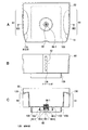
図4は、ポット38、天井部材18およびアダプタ90の断面を示している。図5は、アダプタ90が外された天井部材18および筐体4の上部を示している。図6は、蓋部40を外したポット38の平面、正面および図6のAのVIC−VIC線断面を示している。
FIG. 4 shows a cross section of the
ポット38の蓋部40には開閉部40−1および開閉支持部40−2が備えられ、開閉部40−1は開閉支持部40−2にヒンジ部40−3で回動可能に支持されている。
The
ポット38には原水Wを溜めるポット本体92が備えられ、このポット本体92の底部には給水筒部94が形成されている。この給水筒部94にはポット38の内部側に小径の給水口96−1、底部の外側に大径の給水口96−2が形成されている。
The
給水筒部94には開閉弁の一例として弁機構98が備えられる。この弁機構98には、弁体98−1が摺動可能に設置され、弁体98−1が弁座部98−2と接離可能に設置されている。弁座部98−2は、給水筒部94内に取り付けられ、止水リングなどで止水状態に維持されている。止水リングはゴムなどの止水材で成形された弾性止水手段である。弁体98−1を支持する軸部98−3は給水口96−1側に摺動可能である。この軸部98−3にはコイルバネ98−4が圧縮状態で装着され、ポット38がウォーターサーバー2から離脱した場合、弁体98−1が弁座部98−2側に圧接されて閉止状態に維持される。このとき、原水Wがポット本体92に維持される。
The water
ポット38の底面部100には給水筒部94を包囲して止水連結筒部102が形成されている。この例では、底面部100からの給水筒部94および止水連結筒部102は同一の突出長である。止水連結筒部102は止水連結部の一例であり、アダプタ90に装着される。止水連結部102には止水リング104が装着されており、この止水リング104をアダプタ90によって支持される浄水カートリッジ50の周壁部216(図10参照)に密着させて浄水カートリッジ50との止水状態が図られる。
A water
この止水連結筒部102の周囲には、天井部材18との係合させる係合手段の一例である係合凸部106がポット本体92と一体に形成されている。この例では、係合凸部106は、止水連結筒部102を周回する環状突部であり、止水連結筒部102を超える突出長を備えている。この止水連結筒部102を周回して係合凸部106がポット本体92と一体に形成されている。
Engaging
このポット38を支持する天井部材18には図5に示すように、筐体4に連結される連結筒部108が備えられ、この連結筒部108の上側にポット本体92を載置する載置部110とともに、ポット38の係合凸部106を係合させる係合手段の一例である係合凹部112が備えられる。係合凹部112の内壁側には載置部110の載置面に平行に複数のフランジ部114および切欠き115が形成されている。このフランジ部114にはアダプタ90の最外径より小径のアダプタ装着孔116が形成され、このアダプタ装着孔116にはアダプタ90に係止させる複数の係止部118が形成されている。アダプタ装着孔116は貫通孔部12−3(図1)の一例である。アダプタ90は第3の支持部材の一例である。フランジ部114と係止部118との間にはアダプタ90を収納する収納部120が形成されている。
As shown in FIG. 5, the
フランジ部114の下面側には、カートリッジ収納枠122(図7)を係止させる係止部124が形成されている。カートリッジ収納枠122は、第2の支持部材12−2の一例である。
On the lower surface side of the
アダプタ90には止水連結筒部102に被せられる連結筒部126が形成され、この連結筒部126には傾斜部128を媒介させてフランジ部130が形成されている。このフランジ部130が天井部材18のアダプタ装着孔116側の収納部120に装着される。フランジ部126には天井部材18側の係止部118を係止させる複数の係止部132が天井部材18側の係止部118に対応する位置に形成されている。
The
このアダプタ90は、係止部132を天井部材18のアダプタ装着孔116を潜らせて天井部材18の内側に挿入した後、回転させて係止部118と係止部132とを係合させることにより、アダプタ装着孔116に装着される。
In this
そして、ポット38の係合凸部106は図6のAに示すように、長方形の環状部であり、天井部材18の係合凹部112との係合形態を前後方向に規制している。把手部44によってポット38の内壁面には突出部134が形成されている。
And the engagement
ポット38のレベル表示部42には図6のBに示すように、冷水CWのレベル段階を示す複数のスケール部136が一定の間隔で形成されている。このスケール部136によって冷水CWの給水レベルが確認可能である。
As shown in FIG. 6B, a plurality of
ポット38の各把手部44には図6のCに示すように、内側に立ち上がる傾斜部138が形成されている。
Each
<カートリッジ収納部46(第2の支持部材12−2)> <Cartridge storage portion 46 (second support member 12-2)>
図7のAは、カートリッジ収納枠122の平面を示している。カートリッジ収納枠122には、円筒部140、冷水タンク支持部142および底部144を備える。底部144には給水筒部146、浄水カートリッジ支持部148および通気部150が備えられる。浄水カートリッジ支持部148は、底部144の中央に形成された給水筒部146の周囲に形成された複数の支柱部148−1を備え、各支柱部148−1の頂部には浄水カートリッジ50の底面形状に合致する傾斜面を備えた載置部148−2が形成されている。通気部150は浄水カートリッジ支持部148から離れた位置に形成されている。
7A shows a plane of the
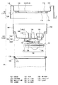
図7のBは、カートリッジ収納部46の筐体構造を示している。冷水タンク支持部142は冷水タンク14の開口縁部に支持される。円筒部140は、天井部材18の係止部124に支持されて天井部材18を介して筐体4に固定される。天井部材18は、筐体4に複数の固定ねじ151によって固定され、筐体4と一体化されている。
FIG. 7B shows the housing structure of the
図8は、天井部材18、カートリッジ収納枠122および冷水タンク14を示している。天井部材18の係止部124に対し、カートリッジ収納枠122の円筒部140の開口縁部が係合可能であり、天井部材18とカートリッジ収納枠122は着脱可能である。
FIG. 8 shows the
冷水タンク支持部142は、円筒部140の下端側の中途部より形成されており、円筒部140の内側に突出させた平坦部である。この冷水タンク支持部142から冷水タンク14に向かって傾斜部152が形成され、この傾斜部152から平坦な突出面部154が形成されている。つまり、底部144は、円筒部140の中途部から冷水タンク14に向かって突出する湾曲面部である。
The cold water
冷水タンク支持部142は円筒部140の下端側の一部と、傾斜面部152で挟まれた狭隘空間部を構成している。
The cold water
底部144の突出面部154には、給水ノズル部156が形成され、この給水ノズル部156を冷水レベルに応じて開閉する弁機構158が備えられる。給水ノズル部156は、カートリッジ収納枠122の内側の給水筒部146に連通しており、冷水タンク14側に浄水Wfを流し込むノズル部の一例である。
A water
弁機構158には弁体160が備えられ、この弁体160の一端が底部144側のヒンジ部162に回動可能に取り付けられ、その他端がフロート52側のヒンジ部164に取り付けられている。弁体160には給水ノズル部156に密着可能な止水部材166が設置されている。冷水レベルによってフロート52が昇降し、弁体160が回動し、給水ノズル部156の先端に弁体160の止水部材166が当接可能である。
The
冷水タンク14には、冷水タンク支持部142に装着されるカーリング処理された開口縁部168が備えられ、この開口縁部168には止水リング170が取り付けられている。この止水リング170には冷水タンク14の内方に突出する止水片172が形成されている。この止水片172は、冷水タンク支持部142に止水リング170とともに挿入され、冷水タンク支持部142の内側にある傾斜部152に密着する。
The
<通気部150>
<
図9は、通気部150を分解して示している。この通気部150には、通気筒174、通気キャップ部175および通気筒支持部176が備えられる。
FIG. 9 shows the
通気筒支持部176は、カートリッジ収納枠122の底部144に形成され、通気筒174が挿入されて支持される。この通気筒支持部176には冷水タンク14側に突出する湾曲底部178が形成され、この湾曲底部178の先端側に通気孔180が開口されている。
The through-
通気筒支持部176には通気筒174に係合させる複数の鉤部182が形成されている。この鉤部182に固定される複数の突出部184が通気筒174に形成されている。この通気筒174には、通気筒支持部176に挿入される挿入部186が形成され、この挿入部186には止水リング188が取り付けられている。挿入部186が通気筒支持部176に挿入されると、通気筒支持部176の内壁面に止水リング188が圧縮状態で密着可能である。このとき、突出部184が鉤部182に鉤止され、通気筒支持部176に通気筒174が固定される。
A plurality of
通気キャップ部175に挿入される挿入部190には同様に止水リング192が取り付けられている。挿入部190が通気キャップ部175に挿入されると、通気キャップ部175の内壁面に止水リング192が圧縮状態で密着可能である。このとき、突出部184は通気キャップ部175の一対の鉤部194に鉤止され、通気キャップ部175が通気筒174に固定される。
A
通気キャップ部175の円筒状の本体部196には通気可能なエアフィルタ200が取り付けられ、本体部196がエアフィルタ200で閉塞されている。このエアフィルタ200にはたとえば、メンブレンフィルタを用いればよい。
An
通気筒支持部176に支持された通気筒174に通気キャップ部175が装着されると、通気孔180を通過する空気は通気キャップ部175のエアフィルタ200を介して外気に通ずる。
When the
<浄水カートリッジ50>
<
図10は、アダプタ90、浄水カートリッジ50およびカートリッジ収納枠122の一部を示している。
FIG. 10 shows a part of the
浄水カートリッジ50は、カートリッジ収納枠122の浄水カートリッジ支持部148に支持されて給水筒部146に装着されるとともに、アダプタ90によって支持される。これにより、転倒が防止され、ポット38と冷水タンク14との間に導水路202を形成する。
The
浄水カートリッジ50にはカートリッジノズル部204が備えられ、このカートリッジノズル部204には止水リング206が取り付けられている。カートリッジノズル部204は給水筒部146に挿入され、止水リング206で止水状態が維持される。
The
浄水カートリッジ50には弁操作ロッド208が設置される。この弁操作ロッド208は、ポット38の弁機構98の開閉操作をする弁操作手段の一例である。
A
図11は、浄水カートリッジ50を分解して示している。浄水カートリッジ50には下側カートリッジ部50−1と上側カートリッジ部50−2が備えられる。下側カートリッジ部50−1の内側に上側カートリッジ部50−2が装着されて超音波溶着などにより一体化されて止水状態に維持される。下側カートリッジ部50−1にはフランジ部210が形成され、上側カートリッジ部50−2の段部212によって係止される。下側カートリッジ部50−1と上側カートリッジ部50−2の間に浄化剤が装填され、上側カートリッジ部50−2の内空間にはたとえば、軟化剤が装填される。
FIG. 11 shows the
上側カートリッジ部50−2の内側には弁操作ロッド支持部214が形成されている。この弁操作ロッド支持部214の周囲部には支持される弁操作ロッド208を包囲する周壁部216が形成されている。
A valve operating
<弁操作ロッド208>
<
図12のAは、弁操作ロッド208の平面を示している。弁操作ロッド208には、直立するロッド部218を中心にし、このロッド部218の下端側にロッド支持部220を備える。ロッド部218は柱体であり、受水口の一例であるロッド支持部220は一例として円盤状であり、複数の通水部222を備えている。
FIG. 12A shows the plane of the
図12のBは、弁機構98、図12のAのXIIB−XIIB線断面を示している。弁機構98に対し、弁操作ロッド208の直立するロッド部218が対応し、弁機構98の弁体98−1に当接して押し上げる。
12B shows a cross section of the
<ウォーターサーバー2の給水機能>
<Water supply function of
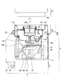
図13は、ウォーターサーバー2の給水可能状態を示している。冷水CWが提供されて冷水タンク14の冷水CWのレベルが低下すると、フロート52が下降し、弁体160が給水ノズル部156より離れ、給水ノズル部156が開状態となる。
FIG. 13 shows a water supply possible state of the
この開状態では、ポット38の原水Wが浄水カートリッジ50を通過して浄水化され、この浄水カートリッジ50から浄水Wfとして給水筒部146および給水ノズル部156を経て冷水タンク14に給水される。常温の浄水Wfは、冷水タンク14の冷水CWに混ざり、冷水CWの温度を上昇させる。この冷水CWの温度上昇は温度センサ60(図3)により検出され、その検出温度に応じて冷却装置48を駆動させる。冷水タンク14の周囲に巻回されている蒸発器58に冷媒が流れ、この冷媒の熱と冷水CWとの熱交換により、冷水CWが設定温度に冷却される。
In this open state, the raw water W in the
図14は、冷水CWのレベル上昇状態、弁機構158の閉止状態を示している。冷水CWのレベルが上昇すると、フロート52が上昇して弁体160が給水ノズル部156に当たり、給水ノズル部156が閉止状態となる。これにより、冷水タンク14に対する浄水Wfの給水が停止される。
FIG. 14 shows a state where the level of the cold water CW is increased and the
<冷水タンク14の通気機能>
<Ventilation function of the
冷水タンク14の冷水CWのレベルが低下する場合、冷水タンク14の負圧化を回避するため冷水タンク14の給気が必要である。図13に示すように、冷水タンク14の冷水レベルが低下すると、カートリッジ収納枠122にある通気部150により、カートリッジ収納部46内の空気が冷水タンク14に流れる。この通気により、冷水タンク14内の空間内に空気が供給される。この通気の際、通気部150のエアフィルタ200により冷水タンク14内に流れる空気が浄化されて供給される。
When the level of the cold water CW in the
浄水Wfの供給により、冷水タンク14の冷水CWのレベルが上昇する場合、加圧化を回避するため、冷水タンク14の排気が必要である。冷水タンク14の冷水レベルが上昇した場合、通気部150により、冷水タンク14側の空気がカートリッジ収納部46内に排気される。
When the level of the cold water CW in the
<ポット38の給水>
<Water supply for
図15は、ポット38への給水を示している。この場合、ウォーターサーバー2の筐体4からポット38を外し、このポット38を移動した後、蓋部40の開閉部40−1を上方に回動させて静止させ、水道栓から給水を行えばよい。
FIG. 15 shows the water supply to the
ポット38を外すことなく、筐体4上にポット38を維持した状態で開閉部40−1を開き、水道栓から給水ホースで水道水を給水してもよく、または市販のボトルから給水してもよい。
Without removing the
<浄水カートリッジ50の排水>
<Drainage of
図16は、浄水カートリッジ50の排水状態を示している。ウォーターサーバー2からポット38が外されると、浄水カートリッジ50は通気状態となる。この状態で、冷水タンク14の冷水CWを排水すると、フロート52が低下して給水ノズル部156から弁体160が外れ、給水ノズル部156を開放状態となる。これにより、浄水カートリッジ50から浄水Wfが冷水タンク14側に降下し、浄水カートリッジ50から浄水Wfが排水される。
FIG. 16 shows the drainage state of the
<浄水カートリッジ50の着脱>
<Removal of
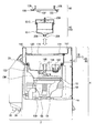
図17は、浄水Wfの排水後の浄水カートリッジ50の着脱を示している。浄水カートリッジ50を着脱するには、筐体4からポット38を外した後、天井部材18からアダプタ90を外せばよい。このアダプタ90は、係止状態から反対方向に回動させることにより、係合状態を解除でき、天井部材18から取り除くことができる。
FIG. 17 shows the attachment / detachment of the
アダプタ90を外すと、天井部材18のアダプタ装着孔116内で浄水カートリッジ50が自立状態となり、この浄水カートリッジ50と天井部材18のアダプタ装着孔116の内壁との間の空間に指を入れ、浄水カートリッジ50に上方に引き抜く力を加えると、カートリッジノズル部204が給水筒部146から外れ、浄水カートリッジ50を取り出すことができる。
When the
このような操作と逆の操作で浄水カートリッジ50を装着すれば、新旧の浄水カートリッジ50を交換することができる。この場合、天井部材18のアダプタ装着孔116内に自立状態にある浄水カートリッジ50と摺接状態にあるアダプタ90を天井部材18のアダプタ装着孔116の縁部に係合させ、回転させて係止状態とする。
If the
<一実施例の特徴事項および効果> <Features and effects of one embodiment>
(カートリッジ収納部46の形態)
(1) 浄水カートリッジ50を収納するカートリッジ収納部46が、天井部材18と、冷水タンク14の蓋部を兼ねるカートリッジ収納枠122とを備えて構成されており、少ない部材で強化された収納空間を形成している。部材数の削減によるウォーターサーバー2の上部側の軽量化を図ることができ、ウォーターサーバー2の設置安定化機能を増強できる。
(Form of the cartridge storage section 46)
(1) The
(2) 天井部材18のアダプタ装着孔116にはアダプタ90が着脱されるので、天井部材18をアダプタ90によって補強できる。
(2) Since the
(3) 天井部材18およびカートリッジ収納枠122のそれぞれはたとえば、強化合成樹脂の成形体であり、ある程度の弾性を備えている。天井部材18では原水Wを収容するポット38からの重量を受け、この重量による応力が天井部材18のフランジ部114からカートリッジ収納枠122に伝達され、これらフランジ部114とカートリッジ収納枠122とが密着状態となる。また、カートリッジ収納枠122からその応力が冷水タンク14の縁部に伝達される。これにより、冷水タンク14と天井部材18との間にカートリッジ収納枠122の冷血筒部108が挟み込まれて圧縮状態で保持され、強固な筐体構造が維持される。つまり、ポット38の原水Wに応じてカートリッジ収納部46の補強状態が得られる。
(3) Each of the
(カートリッジ収納枠122の形態)
(4) カートリッジ収納枠122は、突出面部154を有する底部144と、円筒部140とを備え、立体形状である。この立体形状により、単一の部品でカートリッジ収納部46におけるカートリッジ収納空間を形成することができる。
(Form of cartridge storage frame 122)
(4) The
(5) 円筒部140はたとえば、天井部材18のフランジ部114と冷水タンク14の縁部との間に直立状態で維持される。このため、天井部材18が受ける重量や応力を分散させることなく、冷水タンク14に伝達し、冷水タンク14から支持筐体部6を含む筐体4を介して設置面に伝達できる。ポット38からの重力を回転モーメントに変換させることなく設置面側に伝達でき、ウォーターサーバー2の設置の安定化を図ることができる。
(5) The
(カートリッジ収納枠122と天井部材18の係合関係)
(6) カートリッジ収納枠122の円筒部140の上縁は天井部材18に係合して支持され、天井部材18とカートリッジ収納枠122は着脱可能で強固な係合状態が維持されている。天井部材18を設置すると、カートリッジ収納枠122との係合が図られ、カートリッジ収納枠122と天井部材18とが一体化される。
(Engagement relationship between
(6) The upper edge of the
(天井部材18とアダプタ90の関係)
(7) 天井部材18の透孔・・にはアダプタ90が着脱可能に装着され、天井部材18のフランジ部114がアダプタ90によって補強され、アダプタ90を介してフランジ部114の端部間が橋絡状態となっている。天井部材18のフランジ部114がアダプタ90によって強化され、浄水カートリッジ50の支持強度を高めている。
(Relationship between
(7) The
(カートリッジ収納枠122と冷水タンク14の関係)
(8) カートリッジ収納枠122の膨出部が冷水タンク14の内部に突出しており、冷水タンク14の上部側を利用してカートリッジ収納枠122によるカートリッジ収納空間を拡大している。これにより、冷水タンク14の口径を大きくして冷水CWの収容容積を拡大すれば、カートリッジ収納枠122の膨出部を冷水タンク14に侵入させても冷水CWの収容容積を犠牲にすることなく、カートリッジ収納部46のコンパクト化を図ることができる。
(Relationship between
(8) The bulging portion of the
〔他の実施の形態〕 [Other Embodiments]
ア)天井部材18とポット38の係合関係について、上記実施例では、天井部材18側に係合凹部112、ポット38側に係合凸部106を備えたが、天井部材18側に係合凸部106、ポット38側に係合凹部112を備えてもよい。
A) Regarding the engagement relationship between the
イ)浄水カートリッジ50とカートリッジ収納枠122を一体化し、浄水カートリッジ50に装填される浄化剤や軟化剤を着脱可能としてもよい。
B) The
ウ)ポット38に浄水カートリッジ50を一体化した構成としてもよい。
C) The
エ)筐体4の底面部に該底面部より形状ないし面積の大きい台座を備えてもよい。これにより、筐体4の設置安定性をより高めることができる。
D) A base having a shape or area larger than that of the bottom surface portion may be provided on the bottom surface portion of the
以上説明したように、本発明のウォーターサーバーの最も好ましい実施の形態や実施例について説明した。本発明は、上記記載に限定されるものではない。特許請求の範囲に記載され、または発明を実施するための形態に開示された発明の要旨に基づき、当業者において様々な変形や変更が可能である。斯かる変形や変更が本発明の範囲に含まれることは言うまでもない。
As described above, the most preferred embodiments and examples of the water server of the present invention have been described. The present invention is not limited to the above description. Various modifications and changes can be made by those skilled in the art based on the gist of the invention described in the claims or disclosed in the embodiments for carrying out the invention. It goes without saying that such modifications and changes are included in the scope of the present invention.
本発明のウォーターサーバーによれば、筐体構造の堅牢化と軽量化を図ることができ、堅牢性が高く安定設置機能を高めたウォーターサーバーを実現できる。
According to the water server of the present invention, it is possible to make the housing structure robust and lightweight, and to realize a water server that is highly robust and has a stable installation function.
2 ウォーターサーバー
4 筐体
6 支持筐体部
10 浄水手段
12−1 第1の支持部材
12−2 第2の支持部材
12−3 貫通孔部
14 冷水タンク
W 原水
Wf 浄水
CW 冷水
HW 温水
18 天井部材
20 操作パネル部
22 表示部
24 冷水ボタン
26 温水ボタン
28 ロック・解除ボタン
30 冷水口
32 温水口
34 排水口
36 トレー部
38 ポット
40 蓋部
42 レベル表示部
44 把手部
46 カートリッジ収納部
48 冷却装置
50 浄水カートリッジ
50−1 下側カートリッジ部
50−2 上側カートリッジ部
52 フロート
54 分離板
56 給水筒
58 蒸発器
60 温度センサ
62 冷温水制御部
64 冷水供給路
66 開閉弁
68 ブロックヒーター
70 バイパス路
72 開閉弁
74 温水ヒーター
76 温度センサ
78 排水路
80 排水栓
82 コンプレッサー
84 コンデンサ
86 ドライヤー
88 冷媒管
90 アダプタ
92 ポット本体
94 給水筒部
96−1 給水口
96−2 給水口
98 弁機構
98−1 弁体
98−2 弁座部
98−3 軸部
98−4 コイルバネ
100 底面部
102 止水連結筒部
104 止水リング
106 係合凸部
108 連結筒部
110 載置部
112 係合凹部
114 フランジ部
115 切欠き
116 アダプタ装着孔
118 係止部
120 収納部
122 カートリッジ収納枠
124 係止部
126 連結筒部
128 傾斜部
130 フランジ部
132 係止部
134 突出部
136 スケール部
138 傾斜部
140 円筒部
142 冷水タンク支持部
144 底部
146 給水筒部
148 浄水カートリッジ支持部
148−1 支柱部
148−2 載置部
150 通気部
152 傾斜部
154 突出面部
156 給水ノズル部
158 弁機構
160 弁体
162 ヒンジ部
164 ヒンジ部
166 止水部材
168 開口縁部
170 止水リング
172 止水片
174 通気筒
175 通気キャップ部
176 通気筒支持部
178 湾曲底部
180 通気孔
182 鉤部
184 突出部
186 挿入部
188 止水リング
190 挿入部
192 止水リング
194 鉤部
196 本体部
200 エアフィルタ
202 導水路
204 カートリッジノズル部
206 止水リング
208 弁操作ロッド
210 フランジ部
212 段部
214 弁操作ロッド支持部
216 周壁部
218 ロッド部
220 ロッド支持部
222 通水部
2 Water server 4 Housing 6 Supporting housing unit 10 Water purification means 12-1 First support member 12-2 Second support member 12-3 Through hole 14 Cold water tank W Raw water Wf Clean water CW Cold water HW Hot water 18 Ceiling member 20 Operation Panel 22 Display 24 Cold Water Button 26 Hot Water Button 28 Lock / Release Button 30 Cold Water Port 32 Hot Water Port 34 Drain Port 36 Tray Part 38 Pot 40 Lid Part 42 Level Display Part 44 Handle Part 46 Cartridge Storage Part 48 Cooling Device 50 Water purification cartridge 50-1 Lower cartridge part 50-2 Upper cartridge part 52 Float 54 Separation plate 56 Water supply cylinder 58 Evaporator 60 Temperature sensor 62 Chilled / warm water control part 64 Chilled water supply path 66 Open / close valve 68 Block heater 70 Bypass path 72 Open / close valve 74 Hot water heater 76 Temperature sensor 78 Drainage channel 80 Drain plug 82 Compressor 84 Condenser 86 Dryer 88 Refrigerant pipe 90 Adapter 92 Pot body 94 Water supply cylinder 96-1 Water supply 96-2 Water supply 98 Valve mechanism 98-1 Valve body 98-2 Valve seat 98-3 Shaft part 98-4 Coil spring 100 Bottom face part 102 Water stop connecting cylinder part 104 Water stop ring 106 Engaging protrusion part 108 Connecting cylinder part 110 Placement part 112 Engaging recess part 114 Flange part 115 Notch 116 Adapter mounting hole 118 Locking part DESCRIPTION OF SYMBOLS 120 Storage part 122 Cartridge storage frame 124 Locking part 126 Connection cylinder part 128 Inclination part 130 Flange part 132 Locking part 134 Protrusion part 136 Scale part 138 Inclination part 140 Cylindrical part 142 Chilled water tank support part 144 Bottom part 146 Water supply cylinder part 148 Cartridge support section 148-1 Strut section 48-2 Placement part 150 Ventilation part 152 Inclination part 154 Projection surface part 156 Water supply nozzle part 158 Valve mechanism 160 Valve body 162 Hinge part 164 Hinge part 166 Water stop member 168 Opening edge part 170 Water stop ring 172 Water stop piece 174 Passing cylinder 175 Ventilation cap portion 176 Cylinder passage support portion 178 Curved bottom portion 180 Ventilation hole 182 Gutter portion 184 Projection portion 186 Insertion portion 188 Water stop ring 190 Insertion portion 192 Water stop ring 194 Gutter portion 196 Main body portion 200 Air filter 202 Water guide passage 204 Cartridge nozzle Portion 206 206 Water stop ring 208 Valve operation rod 210 Flange portion 212 Step portion 214 Valve operation rod support portion 216 Peripheral wall portion 218 Rod portion 220 Rod support portion 222 Water flow portion
Claims (3)
前記冷水タンクに浄水を供給する浄水手段を支持する支持筐体部とを備え、
前記支持筐体部が、貫通孔部を形成した第1の支持部材と、前記冷水タンクの開口部を閉じる第2の支持部材とを備えることを特徴とするウォーターサーバー。 A housing having a cold water tank for storing cold water;
A support housing portion that supports water purification means for supplying purified water to the cold water tank,
The water server, wherein the support housing portion includes a first support member having a through-hole portion and a second support member that closes an opening of the cold water tank.
を備え、前記第3の支持部材に浄水カートリッジを貫通させたことを特徴とする請求項1に記載のウォーターサーバー。 Furthermore, a third support member attached to the through hole portion of the first support member;
The water server according to claim 1, wherein a water purification cartridge is passed through the third support member.
前記第1の支持部材に支持され、前記浄水手段を載置し、浄水を通過させる給水部を備える載置部と、
前記冷水タンクの冷水レベルに応じて前記給水部を開閉する弁機構と、
を備えることを特徴とする請求項1または請求項2に記載のウォーターサーバー。
The second support member is
A mounting unit that is supported by the first support member, includes the water supply unit that mounts the water purification means and allows the purified water to pass through,
A valve mechanism for opening and closing the water supply unit according to the cold water level of the cold water tank;
The water server according to claim 1, further comprising:
Priority Applications (1)
| Application Number | Priority Date | Filing Date | Title |
|---|---|---|---|
| JP2015012675A JP6470981B2 (en) | 2015-01-26 | 2015-01-26 | Water server |
Applications Claiming Priority (1)
| Application Number | Priority Date | Filing Date | Title |
|---|---|---|---|
| JP2015012675A JP6470981B2 (en) | 2015-01-26 | 2015-01-26 | Water server |
Publications (2)
| Publication Number | Publication Date |
|---|---|
| JP2016137902A true JP2016137902A (en) | 2016-08-04 |
| JP6470981B2 JP6470981B2 (en) | 2019-02-13 |
Family
ID=56559725
Family Applications (1)
| Application Number | Title | Priority Date | Filing Date |
|---|---|---|---|
| JP2015012675A Active JP6470981B2 (en) | 2015-01-26 | 2015-01-26 | Water server |
Country Status (1)
| Country | Link |
|---|---|
| JP (1) | JP6470981B2 (en) |
Cited By (3)
| Publication number | Priority date | Publication date | Assignee | Title |
|---|---|---|---|---|
| CN108065775A (en) * | 2016-11-11 | 2018-05-25 | 珠海格力电器股份有限公司 | water dispenser |
| JP2019043662A (en) * | 2017-09-07 | 2019-03-22 | ユニケミ株式会社 | Liquid supply device |
| JP2023029136A (en) * | 2021-08-20 | 2023-03-03 | スン ヘ ミュン | Modularized water pail apparatus for water purification and water purifier equipped with the same |
Citations (4)
| Publication number | Priority date | Publication date | Assignee | Title |
|---|---|---|---|---|
| US20050150824A1 (en) * | 2004-01-08 | 2005-07-14 | Kaz, Incorporated | Water filtration tank dispensing system |
| JP2007136304A (en) * | 2005-11-16 | 2007-06-07 | Fnet Planning:Kk | Water purification filter, water purification cartridge, water server tank and water server system |
| US20130015208A1 (en) * | 2010-03-31 | 2013-01-17 | Breville Pty Limited | Water Cooler Apparatus |
| JP2015013691A (en) * | 2014-08-22 | 2015-01-22 | ビクトリージャパン株式会社 | Cold and hot water supplying apparatus |
-
2015
- 2015-01-26 JP JP2015012675A patent/JP6470981B2/en active Active
Patent Citations (4)
| Publication number | Priority date | Publication date | Assignee | Title |
|---|---|---|---|---|
| US20050150824A1 (en) * | 2004-01-08 | 2005-07-14 | Kaz, Incorporated | Water filtration tank dispensing system |
| JP2007136304A (en) * | 2005-11-16 | 2007-06-07 | Fnet Planning:Kk | Water purification filter, water purification cartridge, water server tank and water server system |
| US20130015208A1 (en) * | 2010-03-31 | 2013-01-17 | Breville Pty Limited | Water Cooler Apparatus |
| JP2015013691A (en) * | 2014-08-22 | 2015-01-22 | ビクトリージャパン株式会社 | Cold and hot water supplying apparatus |
Cited By (5)
| Publication number | Priority date | Publication date | Assignee | Title |
|---|---|---|---|---|
| CN108065775A (en) * | 2016-11-11 | 2018-05-25 | 珠海格力电器股份有限公司 | water dispenser |
| CN108065775B (en) * | 2016-11-11 | 2024-04-09 | 珠海格力电器股份有限公司 | Water dispenser |
| JP2019043662A (en) * | 2017-09-07 | 2019-03-22 | ユニケミ株式会社 | Liquid supply device |
| JP2023029136A (en) * | 2021-08-20 | 2023-03-03 | スン ヘ ミュン | Modularized water pail apparatus for water purification and water purifier equipped with the same |
| JP7324527B2 (en) | 2021-08-20 | 2023-08-10 | スン ヘ ミュン | Modularized water trough device and water purifier provided with the same |
Also Published As
| Publication number | Publication date |
|---|---|
| JP6470981B2 (en) | 2019-02-13 |
Similar Documents
| Publication | Publication Date | Title |
|---|---|---|
| JP6476220B2 (en) | Water purifier and refrigerator | |
| JP5529199B2 (en) | Water server | |
| JP6470981B2 (en) | Water server | |
| KR101884736B1 (en) | Under sink type water dispenser | |
| US20060249442A1 (en) | Water filtration system with improved performance | |
| KR20180045756A (en) | Under sink type water dispenser | |
| JP6470980B2 (en) | Water server | |
| CN105890253A (en) | Refrigerator | |
| US20040211713A1 (en) | Multifunctional pure water maker | |
| US9242195B2 (en) | Water filter with features for reduced spilling | |
| JP6470982B2 (en) | Water server | |
| KR200443372Y1 (en) | Cold and hot water purifier | |
| CN112932270A (en) | Water supply device | |
| CN109422342A (en) | Drinking water dispenser | |
| TWM659145U (en) | Countertop multifunctional water purifier | |
| JP2020131113A (en) | Water purification device | |
| JP2015013691A (en) | Cold and hot water supplying apparatus | |
| ES2395274T3 (en) | Domestic refrigerator with a water dispenser set | |
| KR200230320Y1 (en) | Hot and Cold Water Dispenser | |
| CN109708407B (en) | Kettle structure and refrigerator with same | |
| CN223429423U (en) | A combined water purifier | |
| CN222722834U (en) | Water purifying and drinking machine | |
| KR20150042469A (en) | Ice storage tank and water treatment apparatus having the same | |
| KR102438606B1 (en) | Expansion tank for water purifier and water purifier comprising same | |
| JP7067791B2 (en) | Water server unit |
Legal Events
| Date | Code | Title | Description |
|---|---|---|---|
| A621 | Written request for application examination |
Free format text: JAPANESE INTERMEDIATE CODE: A621 Effective date: 20171114 |
|
| A977 | Report on retrieval |
Free format text: JAPANESE INTERMEDIATE CODE: A971007 Effective date: 20180928 |
|
| A131 | Notification of reasons for refusal |
Free format text: JAPANESE INTERMEDIATE CODE: A131 Effective date: 20181023 |
|
| A521 | Request for written amendment filed |
Free format text: JAPANESE INTERMEDIATE CODE: A523 Effective date: 20181214 |
|
| TRDD | Decision of grant or rejection written | ||
| A01 | Written decision to grant a patent or to grant a registration (utility model) |
Free format text: JAPANESE INTERMEDIATE CODE: A01 Effective date: 20190108 |
|
| A61 | First payment of annual fees (during grant procedure) |
Free format text: JAPANESE INTERMEDIATE CODE: A61 Effective date: 20190121 |
|
| R150 | Certificate of patent or registration of utility model |
Ref document number: 6470981 Country of ref document: JP Free format text: JAPANESE INTERMEDIATE CODE: R150 |
|
| R250 | Receipt of annual fees |
Free format text: JAPANESE INTERMEDIATE CODE: R250 |
|
| R250 | Receipt of annual fees |
Free format text: JAPANESE INTERMEDIATE CODE: R250 |
|
| R250 | Receipt of annual fees |
Free format text: JAPANESE INTERMEDIATE CODE: R250 |
|
| R250 | Receipt of annual fees |
Free format text: JAPANESE INTERMEDIATE CODE: R250 |