JP2016142012A - Multi-layered glass body and fitting - Google Patents
Multi-layered glass body and fitting Download PDFInfo
- Publication number
- JP2016142012A JP2016142012A JP2015017632A JP2015017632A JP2016142012A JP 2016142012 A JP2016142012 A JP 2016142012A JP 2015017632 A JP2015017632 A JP 2015017632A JP 2015017632 A JP2015017632 A JP 2015017632A JP 2016142012 A JP2016142012 A JP 2016142012A
- Authority
- JP
- Japan
- Prior art keywords
- glass
- heating foam
- frame
- multilayer
- foam material
- Prior art date
- Legal status (The legal status is an assumption and is not a legal conclusion. Google has not performed a legal analysis and makes no representation as to the accuracy of the status listed.)
- Pending
Links
Images



Landscapes
- Securing Of Glass Panes Or The Like (AREA)
- Special Wing (AREA)
Abstract
Description
本発明は、スペーサを介して三層以上のガラスを配列させた複層ガラス体とこの複層ガラス体を備えた建具に関する。 The present invention relates to a multi-layer glass body in which three or more layers of glass are arranged via a spacer, and a fitting including the multi-layer glass body.
従来、例えば特許文献1に記載された建具は、ペアガラスの板ガラス間の間隙にパネル間シール材とスペーサを配設してペアガラスの端部をグレージングチャンネルで覆い、その外側に設けた補強部材の内部にペアガラスの端部に対向する領域の全幅に亘って加熱発泡材を設けている。そして、火災の際にパネル間シール材から発生する可燃性ガスを加熱発泡材の熱膨張で板ガラス間に封止させるようにしている。
Conventionally, for example, the joinery described in
また、特許文献2に記載された建具では、ペアガラスと框または枠のガラス溝に設けたグレージングチャンネルとを備えており、このグレージングチャンネルの内側面と複層ガラスの屋外側の見付け面との間に加熱発泡材を収納している。そして、火災の際に加熱発泡材が熱膨張することで、框または枠のガラス溝の周縁でグレージングチャンネルが切れてガラス溝と複層ガラスとの隙間から火炎や熱が屋内に侵入して延焼することを防止している。
Moreover, in the joinery described in
ところで、建具の断熱性を上げるために複層ガラスをトリプルガラスに設定し、トリプルガラスの端部に対向する領域の全幅に加熱発泡材を設けたものが知られている。この場合、複層ガラスに設けた屋外側ガラスと屋内側ガラスの間に中間ガラスが存在するため、上述の特許文献1に記載されたペアガラスの建具のように、火災発生時に膨張する加熱発泡材によってガラス間に可燃性ガスを封じ込めたとしても、加熱発泡材によって比較的薄い中間ガラスが部分的に破損してしまうことがある。
By the way, in order to raise the heat insulation of a joinery, what set the double-glazed glass to triple glass, and provided the heating foam material in the full width of the area | region facing the edge part of triple glass is known. In this case, since there is an intermediate glass between the outdoor side glass and the indoor side glass provided in the multilayer glass, like the pair glass joinery described in the above-mentioned
そして、複層ガラスの内部で、例えば中間ガラスの破損した部分と割れ残った部分との間で非加熱面側ガラスに局所的な温度差が生じてしまう。すると、非加熱面側の屋内側ガラスはその温度差を受けて破損するおそれがあった。
その場合、補強部材と複層ガラスとの間に隙間が生じるために加熱面側ガラスが倒れたり複層ガラスが外れたりする等して火炎や熱が屋内外を連通して火災が広がるという不具合があった。
また、特許文献2に記載された建具においても、複層ガラスをトリプルガラスにすると、その屋外側の面とグレージングチャンネルとの間に加熱発泡材を設置したため、加熱発泡材の熱膨張によって複層ガラスが框または枠のガラス溝からずれたり外れたりするおそれがあった。
And a local temperature difference will arise in the non-heated surface side glass between the broken part of the intermediate glass and the remaining cracked part, for example, in the multilayer glass. Then, the indoor side glass on the non-heated surface side may be damaged due to the temperature difference.
In that case, there is a gap between the reinforcing member and the double-glazed glass, so that the heating surface side glass falls down or the double-glazed glass comes off, etc. was there.
Also, in the joinery described in
本発明は、このような課題に鑑みてなされたものであって、三層以上の複層ガラスにおいて、火災発生等の際に、加熱発泡材の熱膨張によって中間ガラスが部分的に破損したり、複層ガラスがずれたり外れたりして火炎や熱が屋内外を流通することを防止するようにした複層ガラス体と建具を提供することを目的とする。 The present invention has been made in view of such problems, and in a multi-layer glass having three or more layers, the intermediate glass may be partially damaged by thermal expansion of the heating foam material in the event of a fire or the like. An object of the present invention is to provide a multi-layer glass body and a joinery which prevent the multi-layer glass from being displaced or detached and preventing flames and heat from circulating indoors and outdoors.
本発明による複層ガラス体は、スペーサを介して三層以上のガラスを配列した複層ガラスと、複層ガラスの端部を覆う支持具と、複層ガラスの中間に位置する中間ガラスの端部近傍に設けた加熱発泡材と、を備えたことを特徴とする。
本発明による複層ガラス体によれば、この複層ガラス体を建具に保持した状態で、火災発生時等に加熱発泡材が発泡して熱膨張することで火炎に近接した加熱面側ガラスと火炎から離れた非加熱面側ガラスの間に位置する中間ガラスを全体に破損することができる。そのため、加熱面側ガラスと非加熱面側ガラスの間での温度差が小さくなり、中間ガラスの一部破損による温度差で非加熱面側ガラスが破損することを防止でき、複層ガラスが枠体等との間で倒れたり外れたりすることや隙間が生じることを防止し、屋内外における火炎や熱の流通を防ぐことができる。
The multi-layer glass body according to the present invention includes a multi-layer glass in which three or more layers of glass are arranged via a spacer, a support covering the end of the multi-layer glass, and an end of the intermediate glass located in the middle of the multi-layer glass. And a heating foam material provided in the vicinity of the portion.
According to the multi-layer glass body according to the present invention, with the multi-layer glass body held in the joinery, the heating surface side glass close to the flame by the foaming and thermal expansion of the heating foam material in the event of a fire, etc. The intermediate glass located between the non-heated surface side glasses away from the flame can be broken as a whole. Therefore, the temperature difference between the heated surface side glass and the non-heated surface side glass is reduced, and the non-heated surface side glass can be prevented from being damaged by the temperature difference due to partial breakage of the intermediate glass. It is possible to prevent the body from falling over or coming off from the body or the like, and to prevent a gap from being generated, and to prevent the flame and heat from being distributed indoors and outdoors.
また、支持具における中間ガラスの端部に対向する位置に加熱発泡材を設けることが好ましい。
中間ガラスの端部に対向する位置の支持具に加熱発泡材を設けることで、火災発生時等に加熱面側ガラスと非加熱面側ガラスとの間で局所的な温度差が生じないように、加熱発泡材を発泡させて中間ガラス全体を割ることができる。
Moreover, it is preferable to provide a heating foam material in the position facing the edge part of the intermediate glass in a support tool.
By providing a heating foam on the support that faces the edge of the intermediate glass, a local temperature difference does not occur between the heated surface side glass and the non-heated surface side glass in the event of a fire. The entire intermediate glass can be broken by foaming the heated foam material.
本発明による建具は、枠体と、枠体内に設けられていてスペーサを介して三層以上のガラスを配列した複層ガラスと、複層ガラスの端部を覆う支持具と、複層ガラスにおける中間ガラスの端部近傍に設けた加熱発泡材と、を備えたことを特徴とする。
本発明による建具によれば、複層ガラスを枠体内に保持した状態で、火災発生時等に複層ガラス内で非加熱面側ガラスに局所的な温度差を生じさせないように、加熱発泡材が熱膨張して中間ガラスを全体に破損させ、加熱面側ガラスから伝熱される非加熱面ガラスの熱分布が不均一となることを抑制できる。そのため、中間ガラスの一部破損によって非加熱面側ガラスに局所的な温度差が生じて非加熱面側ガラスが破損することがない。
A joinery according to the present invention includes a frame, a multi-layer glass provided in the frame and arranged with three or more layers of glass through a spacer, a support covering an end of the multi-layer glass, and a multi-layer glass. And a heating foam material provided in the vicinity of the end of the intermediate glass.
According to the joinery according to the present invention, in the state where the multi-layer glass is held in the frame, a heated foam material is used so as not to cause a local temperature difference in the non-heated surface side glass in the multi-layer glass when a fire occurs. It is possible to suppress the thermal distribution of the non-heated surface glass that is transferred from the heated surface side glass and becomes non-uniform due to thermal expansion and damage to the entire intermediate glass. Therefore, a local temperature difference does not occur in the non-heated surface side glass due to partial breakage of the intermediate glass, and the non-heated surface side glass is not damaged.
また、支持具における少なくとも中間ガラスの端部に対向する位置に加熱発泡材を設けることが好ましい。
火災発生時等に、建具の屋内側ガラスに局所的な温度差を生じさせないように、支持具に設けた加熱発泡材を発泡させて中間ガラス全体を破損することができる。
Moreover, it is preferable to provide a heating foam material in the position which opposes the edge part of at least intermediate glass in a support tool.
In the event of a fire, etc., the intermediate glass can be broken by foaming the heated foam material provided on the support so as not to cause a local temperature difference in the indoor glass of the joinery.
また、加熱発泡材は複層ガラスにおける屋外側ガラスの端部近傍にも設けられ、屋内側ガラスには設けられていないことが好ましい。
加熱発泡材を複層ガラスの中間ガラスと屋外側ガラスの近傍にそれぞれ設けると共に、屋内側ガラス近傍には設けないため、各加熱発泡材が熱膨張した際に屋外側ガラスと支持具の間を加熱発泡材で封止し、中間ガラスを全体に破損できるが、屋内側ガラスには加熱発泡材を設けていないため過大な応力が複層ガラスに働かず、屋外側ガラスと屋内側ガラスを保持できて複層ガラスのずれや外れ等を防止できる。
なお、本発明の複層ガラスにおいて中間ガラスを挟む屋外側ガラスと屋内側ガラスは、火災の際に火炎に近い側が加熱面側ガラスとなり、火炎から離れた側が非加熱面側ガラスとなる。
Moreover, it is preferable that a heating foam material is provided also in the edge part vicinity of the outdoor side glass in a multilayer glass, and is not provided in the indoor side glass.
Since the heating foam is provided in the vicinity of the intermediate glass of the multilayer glass and the outdoor side glass, and not in the vicinity of the indoor side glass, when each heating foam is thermally expanded, the space between the outdoor side glass and the support is Sealed with heated foam material, the intermediate glass can be damaged as a whole, but the indoor side glass is not provided with a heated foam material, so excessive stress does not work on the multi-layer glass, holding the outdoor side glass and the indoor side glass It is possible to prevent misalignment or detachment of the multi-layer glass.
In addition, in the double-sided glass of the present invention, the outdoor side glass and the indoor side glass sandwiching the intermediate glass become the heated surface side glass in the fire and the side away from the flame becomes the non-heated surface side glass.
また、複層ガラスの端部は框体で囲われて前記枠体内に納められ、支持具は複層ガラスの端部に対向する框部であり、該框部に加熱発泡材を設けるようにしてもよい。
この場合でも、框部に設けた加熱発泡材によって複層ガラスの中間ガラスを全体に破損できる。
Further, the end portion of the multi-layer glass is enclosed in a frame and enclosed in the frame body, and the support is a reed portion facing the end portion of the multi-layer glass, and a heating foam material is provided on the reed portion. May be.
Even in this case, the intermediate glass of the multi-layer glass can be broken as a whole by the heating foam material provided in the collar portion.
また、防火用の複層ガラスにおける中間ガラスは屋外側ガラスと屋内側ガラスよりも相対的に弱い強度であること、例えば厚みが薄く形成されていることが好ましい。
この場合には、火災発生時等に中間ガラスの端部近傍に設けた加熱発泡材を熱膨張させることで、複層ガラスの非加熱面側ガラスに局所的な温度差を生じさせないように、中間ガラスの全体を破損させることができる。
Moreover, it is preferable that the intermediate glass in the fireproof multilayer glass is relatively weaker than the outdoor side glass and the indoor side glass, for example, is formed with a small thickness.
In this case, the thermal foaming material provided in the vicinity of the end of the intermediate glass at the time of the occurrence of a fire etc. is thermally expanded so as not to cause a local temperature difference in the non-heated surface side glass of the multilayer glass. The entire intermediate glass can be broken.
本発明による複層ガラス体と建具によれば、複層ガラスを建具に保持させた状態で、火災発生時等に加熱発泡材が発泡して中間ガラスを全体に破損させて非加熱面側ガラスに局所的な温度差が生じることを抑えられる。 According to the multi-layer glass body and the joinery according to the present invention, the non-heated surface side glass is obtained by foaming the heating foam material in the event of a fire or the like, with the multi-layer glass held by the joinery, and damaging the intermediate glass as a whole. It is possible to prevent a local temperature difference from occurring in the substrate.
以下、本発明の実施形態による建具について説明する。
まず、第一実施形態による縦辷り出し窓を図1乃至図4に基づいて説明する。
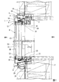
図1及び図2に示す実施形態による建具としての縦辷り出し窓1はアルミと樹脂の複合サッシからなり、図1は縦辷り出し窓1の縦断面図を、図2は水平断面図をそれぞれ示している。本実施形態による縦辷り出し窓1は、躯体の開口部2に上枠3と下枠4と左右の縦枠5とが四角形枠状に形成された枠体6を取り付けている。
そして、枠体6内に開閉可能に納めた障子8は、それぞれアルミと樹脂の複合サッシからなる上框9と下框10と左右の縦框11とからなる四角形枠状の框体12を有し、その内部に三層以上、例えばトリプルガラスからなる複層ガラス13を納めている。
Hereinafter, a fitting according to an embodiment of the present invention will be described.
First, the vertical window according to the first embodiment will be described with reference to FIGS.
1 and 2 is a composite sash made of aluminum and resin, FIG. 1 is a vertical sectional view of the
The
図1において、枠体6の上枠3は、屋外側に設けた金属上枠14と屋内側に設けた樹脂上枠15を連結して構成している。金属上枠14は樹脂製の断熱材16を介して屋外側と屋内側を連結している。框体12の上框9は屋外側に設けた金属上框18と屋内側に設けた樹脂上框19を連結して構成している。
また、下枠4は屋外側に設けた金属下枠20と屋内側に設けた樹脂下枠21を連結して構成している。金属下枠20は樹脂製の断熱材24を介して屋外側と屋内側を連結している。下框10は屋外側に設けた金属下框22と屋内側に設けた樹脂下框23を連結して構成している。
In FIG. 1, the
The
また、図2において、枠体6の左右の縦枠5は屋外側の金属縦枠25と屋内側の樹脂縦枠26とを連結している。また、框体12の左右の縦框11は屋外側の金属縦框27と屋内側の樹脂縦框28とを連結している。
In FIG. 2, the left and right
次に框体12内に納められた複層ガラス13は例えば四角形板状をなす三層のガラスを備え、屋外側ガラス30と中間ガラス31と屋内側ガラス32がそれぞれスペーサ33を挟んで平行に配列されている。屋外側ガラス30は例えば網入りガラスで厚みが最も大きく、屋内側ガラス32は屋外側ガラス30より厚みが小さいか同等に設定されている。中間ガラス31は屋外側ガラス30や屋内側ガラス32よりも厚みが小さく、後述する第一加熱発泡材38a、38bを発泡して熱膨張させることで割れるように設定されている。
この複層ガラス13は四辺の各端部が断面コの字状のグレージングチャンネル35によって覆われている。また、図2に示す水平断面図ではグレージングチャンネル35の外側には断面略コの字状の補強用の支持金具36aが装着され、支持金具36aは縦框11によって覆われている。そして、グレージングチャンネル35の両端部において、屋外側は縦框11における金属縦框27の端部で係止され、屋内側端部は樹脂縦框28で係止されて固定保持されている。
Next, the
The
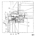
また、図1及び図3に示す上枠3の部分の縦断面図における複層ガラス13の上端部も、グレージングチャンネル35で覆われている。グレージングチャンネル35の外側は断面略コの字状の支持金具36bによって覆われて固定されている。支持金具36bは上框9のガラス溝9aによって覆われている。グレージングチャンネル35の両端部において、その屋外側は上框9の金属上框18の下端部で係止され、屋内側端部は樹脂上框19の下端部で係止されて固定保持されている。
しかも、支持金具36bにおいて、複層ガラス13の中間ガラス31に対向する位置には第一加熱発泡材38aが接着剤等で固定され、屋外側ガラス30に対向する位置には第二加熱発泡材39aが固定されている。なお、屋内側ガラス32に対向する位置には加熱発泡材は設けられていない。
支持金具36bはその長手方向において部分的に切除されており、その部分では第一及び第二加熱発泡材38a,39aはガラス溝9aの金属上框18に固定されている。
Further, the upper end portion of the
In addition, in the support metal fitting 36b, the first
The support fitting 36b is partially cut off in the longitudinal direction, and the first and second
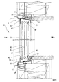
また、図1及び図4に示す下枠4の部分の縦断面図における複層ガラス13の下端部も、グレージングチャンネル35で覆われている。グレージングチャンネル35の外側には断面略コの字状の支持金具36cが装着されている。支持金具36cは下框10のガラス溝10aによって支持されている。グレージングチャンネル35の両端部において、その屋外側は下框10の金属下框22の上端部で係止され、屋内側端部は樹脂下框23の上端部で係止されて固定保持されている。
しかも、支持金具36cにおいて、複層ガラス13の中間ガラス31に対向する位置には第一加熱発泡材38bが接着剤等で固定され、屋外側ガラス30に対向する位置には第二加熱発泡材39bが固定されている。なお、屋内側ガラス32に対向する位置には加熱発泡材は設けられていない。
また、支持金具36cはその長手方向において部分的に切除されており、その部分では第一及び第二加熱発泡材38b、39bはガラス溝10aの金属下框22に固定されている。
Further, the lower end portion of the
Moreover, in the support metal fitting 36c, the first
Further, the support fitting 36c is partly cut in the longitudinal direction, and the first and second heating foams 38b and 39b are fixed to the metal lower bar 22 of the
本第一実施形態による縦辷り出し窓1は上述した構成を備えており、次にその作用について説明する。
本実施形態による縦辷り出し窓1において、例えば屋外側で火災が発生した場合、枠体6と障子8は火炎や熱に晒されて高温になる。この場合、障子8の複層ガラス13の屋外側ガラス30が加熱面側ガラスとなり、屋内側ガラス32が非加熱面側ガラスになる。そして、複層ガラス13における上下框9,10の支持金具36b、36cに設けた第二加熱発泡材39a、39bが発泡して熱膨張し、最も厚みが大きく網入りの屋外側ガラス30の上端及び下端との間隙を封止する。
これと同時に第一加熱発泡材38a、38bも発泡して熱膨張するため、複層ガラス13の上下端部に設けたグレージングチャンネル35を介して中間ガラス31を破損する。
The
In the
At the same time, the
この場合、従来の縦辷り出し窓では、高温の熱や複層ガラスの全幅に設けた加熱発泡材によって中間ガラスが先に割れ、しかもばらついた割れ方を生じるため、中間ガラスの割れた部分と割れ残った部分とで屋内側ガラスに温度差が生じて熱応力で割れてしまう欠点があった。また、複層ガラスの三層ガラスの全幅に亘って加熱発泡材を設けたために熱膨張圧力が大きく、複層ガラスが全体にずれたり外れたりすることがあった。 In this case, in the conventional vertical window, the intermediate glass is first cracked by the high-temperature heat and the heating foam provided in the full width of the double-glazed glass, and also causes a split cracking method. There was a defect that a temperature difference occurred in the indoor side glass with the remaining cracked portion and it was cracked by thermal stress. Moreover, since the heating foam material was provided over the entire width of the triple-layer glass of the double-glazed glass, the thermal expansion pressure was large, and the double-glazed glass sometimes shifted or detached.
これに対し、本実施形態では、支持金具36b、36c上における中間ガラス31の上下端部に対向する近傍位置に第一加熱発泡材38a,38bを設けたため、内部の温度差が大きくなる前に、熱膨張によって中間ガラス31を全体に破損することができる。そのため、屋外側ガラス30と屋内側ガラス32との間の空間で発生する温度差が小さく屋内側ガラス32が割れることを防止できる。
しかも、複層ガラス13の屋内側ガラス32の上下端部に対向する位置には加熱発泡材を設けていないため、複層ガラス13が框体12からずれたり外れたりすることを防止できる。
In contrast, in the present embodiment, since the first
And since the heating foam material is not provided in the position which opposes the upper-lower end part of the
従って、本実施形態では、火炎発生時に、縦辷り出し窓1における障子8の上框9と下框10の間に設けた複層ガラス13は、網入りの屋外側ガラス30と屋内側ガラス32が破損することなく第一加熱発泡材38a,38bと第二加熱発泡材39a、39bで封止状態で保持される。そのため、複層ガラス13と支持金具36b、36cとの間に隙間が発生しないから、火炎や熱が屋外から屋内に流入することを防止して延焼を遅らすことができる。
Therefore, in the present embodiment, the
上述のように本実施形態による縦辷り出し窓1によれば、三層の複層ガラス13の上下端部の中間ガラス31に対向する位置に第一加熱発泡材38a,38bを設けて、中間ガラス31を温度が上昇する前に全体に破損させ、温度差によって屋内側ガラス32が破損することを防止できる。しかも、屋外側ガラス30の上下端部に対向する位置に第二加熱発泡材39a、39bを設けたため、支持金具36b、36cとの間を封止できる。
また、屋内側ガラス32に対向する位置に加熱発泡材を設けないから、加熱発泡材の熱膨張圧力が過大にならず、複層ガラス13が框体12の支持金具36b、36cからずれたり外れたりすることを防止できる。そのため、複層ガラス13と框体12との間に隙間が生じて火炎や熱等が屋内外を流通することを防止できる。
As described above, according to the
Further, since the heating foam material is not provided at the position facing the
なお、本発明による建具と複層ガラス体は、上述した実施形態による縦辷り出し窓1に限定されるものではなく、本発明の要旨を逸脱しない範囲で適宜の変更や置換等が可能である。以下に、本発明の他の実施形態や変形例について説明するが、上述した第一実施形態で説明した部品や部材等と同一または同様なものについては同一の符号を用いて説明する。
The joinery and the multi-layer glass body according to the present invention are not limited to the
(第二実施形態)
以下、本発明の第二実施形態による複層ガラス体を備えたFIX窓41を図5乃至図7に基づいて説明する。
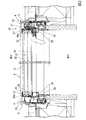
図5及び図6に示す第二実施形態による建具はアルミと樹脂の複合サッシからなるFIX窓(嵌め殺し窓)41である。本第二実施形態によるFIX窓41は、躯体の開口部2に上枠3と下枠4と左右の縦枠5とが四角形枠状に形成された枠体6を取り付けている。枠体6内には例えばトリプルガラスから複層ガラス13が装着されている。
(Second embodiment)
Hereinafter, a
The joinery according to the second embodiment shown in FIGS. 5 and 6 is a FIX window (fitting window) 41 made of a composite sash of aluminum and resin. In the
図5において、FIX窓41の上枠3は屋外側に設けた金属上枠14と屋内側に設けた樹脂上枠15を連結して構成し、下枠4は屋外側に設けた金属下枠20と屋内側に設けた樹脂下枠21を連結して構成している。また、図6において、左右の縦枠5は屋外側に設けた金属縦枠25と屋内側に設けた樹脂縦枠26を連結して構成している。
そして、図5において、上枠3の金属上枠14と樹脂上枠15の間にはパッキン42を介して複層ガラス13の上端を保持する呑み込み部43が形成されている。また、下枠4の金属下枠20と樹脂下枠21の間にはパッキン42を介して複層ガラス13の下端を保持する呑み込み部44が形成されている。
In FIG. 5, the
In FIG. 5, a squeezed
同様に、図6において、左右の縦枠5における金属縦枠25と複数の樹脂ホロー部を形成した樹脂縦枠26との間にはパッキン42を介して複層ガラス13の左右端を保持する呑み込み部45、45がそれぞれ形成されている。また、呑み込み部45内には複層ガラス13の左右両端を囲うように断面略コの字形状の支持金具47がそれぞれ配設され、支持金具47の両端はパッキン42に当接または近接する位置に保持されている。
Similarly, in FIG. 6, the left and right ends of the
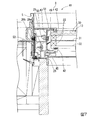
左右の縦枠5の部分は対称形状であるから、図7に示す一方の縦枠5の部分によって代表して以下に説明する。図7に示す支持金具47において、複層ガラス13の中間ガラス31の端部に対向する位置に第一加熱発泡材49が設置されている。第一加熱発泡材49は例えばねじ50で支持金具47と金属縦枠25を貫通して固定されているが、接着剤等で固定されていてもよい。また、支持金具47における屋外側ガラス30の端部に対向する位置には第二加熱発泡材51が設置され、第二加熱発泡材51は例えば接着剤等で支持金具47に固定されている。そして、屋内側ガラス32の両端に対向する位置には加熱発泡材は設置されていない。
また、金属縦枠25と支持金具47の間には樹脂縦枠26に形成した複数の樹脂ホロー部26a、26bが形成されており、樹脂ホロー部26a、26bの境界をなす壁部には別個の加熱発泡材53が固定されている。火災発生時には別個の加熱発泡材53が発泡して熱膨張することで樹脂ホロー部26aの形態を保持して溶解する他の樹脂ホロー部26bを留めて金属縦枠25と支持金具47の間を封止する。
Since the portions of the left and right
Further, a plurality of resin
従って、本第二実施形態によるFIX窓41によれば、火災発生時等には、複層ガラス13の左右両端の屋外側ガラス30に対向する第二加熱発泡材51が熱膨張して支持金具47と網入りの屋外側ガラス30との空間を封止して火炎や熱等が屋内外を流通することを防止できる。
また、これと同時に、中間ガラス31に対向する第一加熱発泡材49は複層ガラス13内の温度が上昇する前に熱膨張して中間ガラス31全体を破損させ、屋外側ガラス30と屋内側ガラスの間の空間内の温度差を小さくできる。これによって、屋内側ガラス32が
温度差によって破損することを防止でき、複層ガラス13の端部がずれたり支持金具47から外れたりすることを防止して、火炎や熱が屋内外を流通することを抑制できる。
しかも、屋内側ガラス32に対向する位置に加熱発泡材を設けないから、火災発生時に加熱発泡材の熱膨張が過大にならず、複層ガラス13が枠体6の支持金具47からずれたり外れたりすることを防止できる。そのため、複層ガラス13と支持金具47との間に隙間が生じて火炎や熱等が屋内外を流通することを防止できる。
Therefore, according to the
At the same time, the
In addition, since the heating foam material is not provided at the position facing the
なお、上述した各実施形態では、複層ガラス13の屋外側ガラス30と中間ガラス31の端部に対向して第一加熱発泡材38a、38b、49と第二加熱発泡材39a、39b、51を個別に設けたが、各加熱発泡材は連続して一体に形成してもよい。また、屋外側ガラス30に対向する第二加熱発泡材39a、39b、51は設けなくてもよい。この場合でも第一加熱発泡材38a、38b、49の熱膨張で複層ガラス13と支持金具との間を封止できる。
また、複層ガラス13はトリプルガラスで構成したが、本発明では三層ガラスに限らず、四層以上のガラスで構成してもよい。この場合、屋外側ガラス30と屋内側ガラス32を除く中間の2枚以上のガラスが中間ガラス31となる。
In each of the above-described embodiments, the first
Moreover, although the
また、上述した各実施形態では第一加熱発泡材38a、38b、49及び第二加熱発泡材39a、39b、51を中間ガラス31と屋外側ガラス30に対向する位置で支持金具47に設けたが、これに限定されるものではなく、これら中間ガラス31と屋外側ガラス30の端部の近傍に配設すればよい。例えば図8に示すように、第一加熱発泡材49(38a、38b)は中間ガラス31の近傍のスペーサ33に設置したり、或いは中間ガラス31に直接設置したりしてもよい。これらの場合でも、火災発生時には確実に中間ガラス31を破損できる。また、屋外側ガラス30についても第二加熱発泡材51(39a、39b)を同様にスペーサ33や屋外側ガラス30等に設置できる。
In each of the above-described embodiments, the first
また、上述した第一実施形態では第一及び第二加熱発泡材38a、38b、39a、39bを複層ガラス13の上下端部付近に設けたが左右端部付近に設けてもよい。同様に、第二実施形態では第一及び第二加熱発泡材49、50は複層ガラス13の左右端部付近に設けたが、上下端部付近に設けてもよい。或いは複層ガラス13の上下左右の端部付近にそれぞれ設けてもよい。
In the first embodiment described above, the first and
なお、上述した実施形態や変形例等による建具では、複層ガラス13のスペーサ33は一般的にはアルミ合金製であるが、これに代えて樹脂で形成してもよい。
即ち、従来の建具においては、複層ガラス13のスペーサ33を樹脂で形成すると、火災時にスペーサ33が熱によって溶融や変形等してしまい、各ガラスが倒れる等して火炎が屋内外に流通する可能性があった。
本発明では、複層ガラス13における屋外側ガラス30、中間ガラス31そして屋内側ガラス32間の各スペーサ33の下部に第一及び第二加熱発泡材39b、38bを配置しているため、火災時にスペーサ33は火炎から保護される。そのため、スペーサ33が樹脂であっても火災の際に溶融や変形等することを防止できる。
このような樹脂製のスペーサ33を備えた複層ガラス13の下部に第二加熱発泡材38bを設置する構造は、三層以上のガラスを備えた複層ガラス13に限られず、ペアガラス等の複層ガラスにおいても採用できる。
In addition, in the joinery by embodiment mentioned above, a modification, etc., although the
That is, in the conventional joinery, when the
In the present invention, since the first and second
The structure in which the second
なお、第一実施形態における框体12の上框9、下框10、縦框11は框部を構成し、支持金具36b、36c、47は支持具を構成する。
また、上述の実施形態では、屋外側に火災が発生した場合について説明したが、本発明は屋内側に火災が発生した場合にも適用できる。この場合、複層ガラス13の屋内側ガラス32が加熱面側ガラスとなり、屋外側ガラス30が非加熱面側ガラスになる。
なお、本発明による建具として、縦辷り出し窓1やFIX窓41を例にとって説明したが、本発明はこれに限定されるものではなく、横辷り出し窓、引き違い窓、連窓や単窓等、或いは各種のドア等にも適用できる。
In the first embodiment, the
Moreover, although the above-mentioned embodiment demonstrated the case where a fire occurred on the outdoor side, this invention is applicable also when a fire occurs on the indoor side. In this case, the
In addition, although the vertical facing
1 縦辷り出し窓
3 上枠
4 下枠
5 縦枠
6 枠体
8 障子
9 上框
10 下框
11 縦框
13 複層ガラス
33 スペーサ
35 グレージングチャンネル
36a,36b,36c、47 支持金具
38a、38b、49 第一加熱発泡材
39a、39b、51 第二加熱発泡材
41 FIX窓
43,44、45 呑み込み部
DESCRIPTION OF
Claims (7)
前記複層ガラスの端部を覆う支持具と、
前記複層ガラスの中間に位置する中間ガラスの端部近傍に設けた加熱発泡材と、
を備えたことを特徴とする複層ガラス体。 Double-layer glass in which three or more layers of glass are arranged through a spacer;
A support covering an end of the multilayer glass;
A heating foam provided in the vicinity of the end of the intermediate glass located in the middle of the multilayer glass;
A multilayer glass body characterized by comprising:
前記枠体内に設けられていてスペーサを介して三層以上のガラスを配列した複層ガラスと、
前記複層ガラスの端部を覆う支持具と、
前記複層ガラスにおける中間ガラスの端部近傍に設けた加熱発泡材と、
を備えたことを特徴とする建具。 A frame,
Double-layer glass provided in the frame and arranged with three or more layers of glass through a spacer;
A support covering an end of the multilayer glass;
A heating foam provided in the vicinity of the end of the intermediate glass in the multilayer glass;
Joinery characterized by comprising.
The joinery according to any one of claims 3 to 6, wherein the intermediate glass in the multi-layer glass has lower strength than the outdoor side glass and the indoor side glass.
Priority Applications (1)
| Application Number | Priority Date | Filing Date | Title |
|---|---|---|---|
| JP2015017632A JP2016142012A (en) | 2015-01-30 | 2015-01-30 | Multi-layered glass body and fitting |
Applications Claiming Priority (1)
| Application Number | Priority Date | Filing Date | Title |
|---|---|---|---|
| JP2015017632A JP2016142012A (en) | 2015-01-30 | 2015-01-30 | Multi-layered glass body and fitting |
Publications (1)
| Publication Number | Publication Date |
|---|---|
| JP2016142012A true JP2016142012A (en) | 2016-08-08 |
Family
ID=56569995
Family Applications (1)
| Application Number | Title | Priority Date | Filing Date |
|---|---|---|---|
| JP2015017632A Pending JP2016142012A (en) | 2015-01-30 | 2015-01-30 | Multi-layered glass body and fitting |
Country Status (1)
| Country | Link |
|---|---|
| JP (1) | JP2016142012A (en) |
Cited By (4)
| Publication number | Priority date | Publication date | Assignee | Title |
|---|---|---|---|---|
| JP2018168585A (en) * | 2017-03-29 | 2018-11-01 | Ykk Ap株式会社 | Door body and fixture |
| JP2019065562A (en) * | 2017-09-29 | 2019-04-25 | 株式会社Lixil | Joiner |
| JP2022182523A (en) * | 2021-05-28 | 2022-12-08 | Ykk Ap株式会社 | Fitting and manufacturing method of fitting |
| JP2024005925A (en) * | 2022-06-30 | 2024-01-17 | 株式会社Lixil | fittings |
Citations (5)
| Publication number | Priority date | Publication date | Assignee | Title |
|---|---|---|---|---|
| JPH0612694U (en) * | 1991-08-01 | 1994-02-18 | 株式会社トーモク | Fireproof device for wooden sash with open / close glass door |
| WO2002084062A1 (en) * | 2001-04-10 | 2002-10-24 | Vkr Holding A/S | Fire retarding window |
| JP2004232294A (en) * | 2003-01-29 | 2004-08-19 | Heilen Haus:Kk | Fireproof window structure |
| JP2013019116A (en) * | 2011-07-07 | 2013-01-31 | Lixil Corp | Multilayered glass panel, sash, and opening device |
| JP2014208568A (en) * | 2013-03-28 | 2014-11-06 | Agc−Lixilウィンドウテクノロジー株式会社 | Multiple glass shoji and frame body for multiple glass shoji |
-
2015
- 2015-01-30 JP JP2015017632A patent/JP2016142012A/en active Pending
Patent Citations (5)
| Publication number | Priority date | Publication date | Assignee | Title |
|---|---|---|---|---|
| JPH0612694U (en) * | 1991-08-01 | 1994-02-18 | 株式会社トーモク | Fireproof device for wooden sash with open / close glass door |
| WO2002084062A1 (en) * | 2001-04-10 | 2002-10-24 | Vkr Holding A/S | Fire retarding window |
| JP2004232294A (en) * | 2003-01-29 | 2004-08-19 | Heilen Haus:Kk | Fireproof window structure |
| JP2013019116A (en) * | 2011-07-07 | 2013-01-31 | Lixil Corp | Multilayered glass panel, sash, and opening device |
| JP2014208568A (en) * | 2013-03-28 | 2014-11-06 | Agc−Lixilウィンドウテクノロジー株式会社 | Multiple glass shoji and frame body for multiple glass shoji |
Cited By (8)
| Publication number | Priority date | Publication date | Assignee | Title |
|---|---|---|---|---|
| JP2018168585A (en) * | 2017-03-29 | 2018-11-01 | Ykk Ap株式会社 | Door body and fixture |
| JP2019065562A (en) * | 2017-09-29 | 2019-04-25 | 株式会社Lixil | Joiner |
| JP2022182523A (en) * | 2021-05-28 | 2022-12-08 | Ykk Ap株式会社 | Fitting and manufacturing method of fitting |
| JP7697821B2 (en) | 2021-05-28 | 2025-06-24 | Ykk Ap株式会社 | Fittings and manufacturing method thereof |
| JP2025120400A (en) * | 2021-05-28 | 2025-08-15 | Ykk Ap株式会社 | Building materials and methods for manufacturing building materials |
| JP2025120402A (en) * | 2021-05-28 | 2025-08-15 | Ykk Ap株式会社 | Building materials and methods for manufacturing building materials |
| JP2024005925A (en) * | 2022-06-30 | 2024-01-17 | 株式会社Lixil | fittings |
| JP7801184B2 (en) | 2022-06-30 | 2026-01-16 | 株式会社Lixil | Building materials |
Similar Documents
| Publication | Publication Date | Title |
|---|---|---|
| JP6353307B2 (en) | Resin fireproof fittings | |
| JP5055321B2 (en) | Resin joinery | |
| JP5148549B2 (en) | Resin joinery | |
| JP6396673B2 (en) | Resin window | |
| JP6675934B2 (en) | Door device | |
| JP2016142012A (en) | Multi-layered glass body and fitting | |
| JP6683445B2 (en) | Joinery | |
| KR20190011380A (en) | The insulation glass frames | |
| JP6700967B2 (en) | Joinery | |
| JP6173782B2 (en) | Glass window | |
| JP2016142014A (en) | Joinery | |
| JP6843684B2 (en) | Joinery | |
| JPH09184373A (en) | Fitting structure of heat insulating fittings | |
| JP6321456B2 (en) | Resin frame and window for joinery | |
| JP2017061832A (en) | Fittings | |
| JP6155154B2 (en) | sash | |
| JP2018145605A (en) | Joinery | |
| JP7204535B2 (en) | fireproof fittings | |
| JP7189032B2 (en) | Fittings | |
| JP6415886B2 (en) | Joinery | |
| JP2016176244A (en) | Fireproof fitting | |
| KR102550053B1 (en) | Aluminum system window for fireproof | |
| JP7123027B2 (en) | Fittings | |
| JP7715603B2 (en) | Fireproof fittings | |
| JP2016142019A (en) | Joinery |
Legal Events
| Date | Code | Title | Description |
|---|---|---|---|
| A621 | Written request for application examination |
Free format text: JAPANESE INTERMEDIATE CODE: A621 Effective date: 20170727 |
|
| A977 | Report on retrieval |
Free format text: JAPANESE INTERMEDIATE CODE: A971007 Effective date: 20180514 |
|
| A131 | Notification of reasons for refusal |
Free format text: JAPANESE INTERMEDIATE CODE: A131 Effective date: 20180522 |
|
| A02 | Decision of refusal |
Free format text: JAPANESE INTERMEDIATE CODE: A02 Effective date: 20181113 |