JP2016181402A - Light source module and lighting apparatus - Google Patents

Light source module and lighting apparatus Download PDF

Info

Publication number
JP2016181402A
JP2016181402A JP2015061159A JP2015061159A JP2016181402A JP 2016181402 A JP2016181402 A JP 2016181402A JP 2015061159 A JP2015061159 A JP 2015061159A JP 2015061159 A JP2015061159 A JP 2015061159A JP 2016181402 A JP2016181402 A JP 2016181402A
Authority
JP
Japan
Prior art keywords
light source
substrate
cover
support
source module
Prior art date
Legal status (The legal status is an assumption and is not a legal conclusion. Google has not performed a legal analysis and makes no representation as to the accuracy of the status listed.)
Pending
Application number
JP2015061159A
Other languages
Japanese (ja)
Inventor
松本 弘樹
Hiroki Matsumoto
弘樹 松本
Current Assignee (The listed assignees may be inaccurate. Google has not performed a legal analysis and makes no representation or warranty as to the accuracy of the list.)
Toshiba Lighting and Technology Corp
Original Assignee
Toshiba Lighting and Technology Corp
Priority date (The priority date is an assumption and is not a legal conclusion. Google has not performed a legal analysis and makes no representation as to the accuracy of the date listed.)
Filing date
Publication date
Application filed by Toshiba Lighting and Technology Corp filed Critical Toshiba Lighting and Technology Corp
Priority to JP2015061159A priority Critical patent/JP2016181402A/en
Publication of JP2016181402A publication Critical patent/JP2016181402A/en
Pending legal-status Critical Current

Links

Images

Landscapes

  • Fastening Of Light Sources Or Lamp Holders (AREA)
  • Non-Portable Lighting Devices Or Systems Thereof (AREA)

Abstract

【課題】組み立て性を向上させた光源モジュール及び照明器具を提供する。【解決手段】支持体21と、基板25と、光源26と、カバー22とを備えた光源モジュールである。基板25は、支持体21に支持される。光源26は、基板25に設けられる。カバー22は、内部に空間を有し、前記空間に向けて光源26の光が出射されるように、支持体21と固定される。カバー22は、前記空間方向に段差状に形成された載置部22aを有する。基板25は、その少なくとも一部が載置部22aの段差部分に収容されているとともに、載置部22aと支持体21との間に挟み込まれている。【選択図】図5A light source module and a lighting fixture with improved assemblability are provided. The light source module includes a support body, a substrate, a light source, and a cover. The substrate 25 is supported by the support 21. The light source 26 is provided on the substrate 25. The cover 22 has a space inside, and is fixed to the support 21 so that light from the light source 26 is emitted toward the space. The cover 22 has a placement portion 22a formed in a step shape in the space direction. At least a part of the substrate 25 is accommodated in a stepped portion of the placement portion 22 a and is sandwiched between the placement portion 22 a and the support 21. [Selection] Figure 5

Description

本発明の実施形態は、光源モジュール及び照明器具に関する。   Embodiments described herein relate generally to a light source module and a lighting fixture.

天井に取り付けられて室内を照明する照明器具がある。照明器具は、光源モジュールと、この光源モジュールを収容する器具本体と、を有する。光源モジュールは、金具等を用いて器具本体に着脱自在に取り付けられる。このような照明器具において、組み立て性の向上が望まれる。   There are lighting fixtures that are attached to the ceiling and illuminate the room. The lighting fixture includes a light source module and a fixture body that accommodates the light source module. The light source module is detachably attached to the instrument body using a metal fitting or the like. In such a luminaire, an improvement in assemblability is desired.

特開2014−78426号公報JP 2014-78426 A

本発明の実施形態は、組み立て性を向上させた光源モジュール及び照明器具を提供する。   Embodiments of the present invention provide a light source module and a lighting fixture with improved assemblability.

本発明の実施形態によれば、支持体と、基板と、光源と、カバーとを備えた光源モジュールが提供される。前記基板は、前記支持体に支持される。前記光源は、前記基板に設けられる。前記カバーは、内部に空間を有し、前記空間に向けて前記光源の光が出射されるように、前記支持体と固定される。前記カバーは、前記空間方向に段差状に形成された載置部を有する。前記基板は、その少なくとも一部が前記載置部の段差部分に収容されているとともに、前記載置部と前記支持体との間に挟み込まれている。   According to the embodiment of the present invention, a light source module including a support, a substrate, a light source, and a cover is provided. The substrate is supported by the support. The light source is provided on the substrate. The cover has a space inside and is fixed to the support so that light from the light source is emitted toward the space. The cover has a placement portion formed in a step shape in the space direction. At least a part of the substrate is accommodated in a step portion of the mounting portion, and is sandwiched between the mounting portion and the support.

本発明の実施形態によれば、組み立て性を向上させた光源モジュール及び照明器具を提供することができる。   According to the embodiment of the present invention, it is possible to provide a light source module and a lighting fixture with improved assemblability.

本実施形態の照明器具の斜視図である。It is a perspective view of the lighting fixture of this embodiment. 本実施形態の照明器具の一部の斜視図である。It is a one part perspective view of the lighting fixture of this embodiment. 図3(a)及び図3(b)は、本実施形態の照明器具の一部の斜視図である。FIG. 3A and FIG. 3B are perspective views of a part of the lighting fixture of the present embodiment. 本実施形態の照明器具の一部の分解斜視図である。It is a partial exploded perspective view of the lighting fixture of this embodiment. 本実施形態の照明器具の一部を示す図である。It is a figure which shows a part of lighting fixture of this embodiment. 本実施形態の照明器具の一部の分解図である。It is a partial exploded view of the lighting fixture of this embodiment. 本実施形態の別の照明器具の一部を示す図である。It is a figure which shows a part of another lighting fixture of this embodiment. 本実施形態の別の照明器具の一部の分解図である。It is a partial exploded view of another lighting fixture of this embodiment. 照明器具の内部を説明する図である。It is a figure explaining the inside of a lighting fixture. 図10(a)〜図10(c)は、光源モジュールと器具本体との取り付けを説明する図である。Fig.10 (a)-FIG.10 (c) are figures explaining attachment of a light source module and an instrument main body.

実施形態に係る発明は、支持体と;前記支持体に支持される基板と;前記基板に設けられた光源と;内部に空間を有し、前記空間に向けて前記光源の光が出射されるように、前記支持体と固定されるカバーと;を備え、前記カバーは、前記空間方向に段差状に形成された載置部を有しており、前記基板は、その少なくとも一部が前記載置部の段差部分に収容されているとともに、前記載置部と前記支持体との間に挟み込まれている光源モジュールである。   The invention according to the embodiment includes a support, a substrate supported by the support, a light source provided on the substrate, a space inside, and light from the light source is emitted toward the space. The cover is fixed to the support body, and the cover has a mounting portion formed in a step shape in the space direction, and at least a part of the substrate is described above. The light source module is housed in a step portion of the placement portion and is sandwiched between the placement portion and the support.

また、前記載置部は前記基板の長手方向に沿って設けられている光源モジュールである。   Further, the mounting portion is a light source module provided along the longitudinal direction of the substrate.

また、前記支持体は、両端に湾曲部を有し、前記カバーは、前記載置部に連結して前記湾曲部に接触する屈曲部を有し、前記屈曲部間の幅は、前記湾曲部間の幅より小さく、前記載置部は、前記基板を押圧固定している光源モジュールである。   In addition, the support body has curved portions at both ends, the cover has a bent portion that is connected to the mounting portion and contacts the curved portion, and the width between the bent portions is the curved portion. The mounting portion is a light source module that presses and fixes the substrate.

また、前記湾曲部は前記屈曲部間の幅を広げるように前記カバーに取り付けられ、前記載置部は前記支持体の方向に向かう力により前記基板と接触している光源モジュールである。   The curved portion is attached to the cover so as to widen the width between the bent portions, and the mounting portion is a light source module that is in contact with the substrate by a force toward the support.

実施形態に係る発明は、請求項1から4のいずれか1つに記載の光源モジュールと;前記光源モジュールを取り付ける器具本体と;を備えた照明器具である。   The invention which concerns on embodiment is a lighting fixture provided with the light source module as described in any one of Claim 1 to 4; and the instrument main body which attaches the said light source module.

以下に、本発明の各実施の形態について図面を参照しつつ説明する。
なお、図面は模式的または概念的なものであり、各部分の厚みと幅との関係、部分間の大きさの比率などは、必ずしも現実のものと同一とは限らない。また、同じ部分を表す場合であっても、図面により互いの寸法や比率が異なって表される場合もある。
なお、本願明細書と各図において、既出の図に関して前述したものと同様の要素には同一の符号を付して詳細な説明は適宜省略する。
Embodiments of the present invention will be described below with reference to the drawings.
The drawings are schematic or conceptual, and the relationship between the thickness and width of each part, the size ratio between the parts, and the like are not necessarily the same as actual ones. Further, even when the same part is represented, the dimensions and ratios may be represented differently depending on the drawings.
Note that, in the present specification and each drawing, the same elements as those described above with reference to the previous drawings are denoted by the same reference numerals, and detailed description thereof is omitted as appropriate.

(本実施形態)
図1は、本実施形態の照明器具の斜視図である。
図2は、本実施形態の照明器具の一部の斜視図である。
図3(a)及び図3(b)は、本実施形態の照明器具の一部の斜視図である。
図4は、本実施形態の照明器具の一部の分解斜視図である。
図5は、本実施形態の照明器具の一部を示す図である。
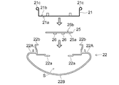
図6は、本実施形態の照明器具の一部の分解図である。
図7は、本実施形態の別の照明器具の一部を示す図である。
図8は、本実施形態の別の照明器具の一部の分解図である。
(This embodiment)
FIG. 1 is a perspective view of the lighting apparatus of the present embodiment.
FIG. 2 is a perspective view of a part of the lighting apparatus of the present embodiment.
FIG. 3A and FIG. 3B are perspective views of a part of the lighting fixture of the present embodiment.
FIG. 4 is an exploded perspective view of a part of the lighting apparatus of the present embodiment.
FIG. 5 is a diagram showing a part of the lighting apparatus of the present embodiment.
FIG. 6 is an exploded view of a part of the lighting apparatus of the present embodiment.
FIG. 7 is a diagram showing a part of another lighting fixture of the present embodiment.
FIG. 8 is an exploded view of a part of another lighting fixture of the present embodiment.

図2は、器具本体10を取り外した状態を示している。図3(a)及び図3(b)は、光源モジュール20を取り外した状態を示している。図4は、図3(a)の光源モジュール20の分解斜視図である。図5及び図7は、光源モジュール20の側面図である。図6及び図8は、光源モジュール20において、支持体21とカバー22との間で基板25を固定することを示している。   FIG. 2 shows a state where the instrument body 10 is removed. 3A and 3B show a state where the light source module 20 is removed. FIG. 4 is an exploded perspective view of the light source module 20 of FIG. 5 and 7 are side views of the light source module 20. 6 and 8 show that the substrate 25 is fixed between the support 21 and the cover 22 in the light source module 20.

図1に表すように、照明器具100は、器具本体10と、光源モジュール20と、を備える。照明器具100は、光源モジュール20を下方に向けた状態で室内の天井面に取り付けられる。器具本体10がネジ等によって天井面に取り付けられる。器具本体10は、光源モジュール20の支持に用いられるとともに、天井などの取付対象への照明器具100の取り付けに用いられる。照明器具100は、室内に光を照射する。なお、照明器具100は、天井面に限ることなく、例えば、壁面などに取り付けても良い。また、複数の照明器具100を連結させても良い。   As illustrated in FIG. 1, the lighting fixture 100 includes a fixture body 10 and a light source module 20. The luminaire 100 is attached to the indoor ceiling surface with the light source module 20 facing downward. The instrument body 10 is attached to the ceiling surface with screws or the like. The fixture body 10 is used for supporting the light source module 20 and for attaching the lighting fixture 100 to an attachment target such as a ceiling. The lighting fixture 100 irradiates light indoors. In addition, you may attach the lighting fixture 100 to a wall surface etc., for example, without restricting to a ceiling surface. Moreover, you may connect the some lighting fixture 100. FIG.

図2に表すように、器具本体10は、筐体11と、取付金具14と、電源回路15と、端子台16と、を備える。また、筐体11は、反射板12と、端板13と、を備える。   As shown in FIG. 2, the instrument main body 10 includes a housing 11, a mounting bracket 14, a power supply circuit 15, and a terminal block 16. The housing 11 includes a reflecting plate 12 and an end plate 13.

筐体11は、光源モジュール20の一部を収容するための凹部11aを有する。また、筐体11には、照明器具100を天井面などに取り付けるための金具(例えば、ネジ)や電源回路15に電力を供給する電源ケーブルなどを通すための複数の開口が設けられる。   The housing 11 has a recess 11 a for accommodating a part of the light source module 20. In addition, the housing 11 is provided with a plurality of openings for passing metal fittings (for example, screws) for attaching the lighting fixture 100 to a ceiling surface or the like, a power supply cable for supplying power to the power supply circuit 15, and the like.

筐体11には、鉄、アルミニウム、または、ステンレスなどの金属材料が用いられる。筐体11に金属材料を用いることにより、器具本体10の耐久性を高めることができる。筐体11には、樹脂材料を用いても良い。   The housing 11 is made of a metal material such as iron, aluminum, or stainless steel. By using a metal material for the housing 11, the durability of the instrument body 10 can be increased. A resin material may be used for the housing 11.

反射板12は、光源モジュール20内の光源26から照射された光を反射する。反射板12によって反射された光は、照明器具100の下方に向かう。
端板13は、反射板12の長手方向の両端に設けられている。筐体11の凹部11aは、反射板12及び端板13に囲まれた部分である。
The reflector 12 reflects the light emitted from the light source 26 in the light source module 20. The light reflected by the reflector 12 travels below the lighting fixture 100.
The end plates 13 are provided at both ends of the reflecting plate 12 in the longitudinal direction. The recess 11 a of the housing 11 is a portion surrounded by the reflection plate 12 and the end plate 13.

取付金具14は、ネジ止めなどにより、筐体11の凹部11a内に取り付けられる。取付金具14は、光源モジュール20の保持部材23に設けられた弾性体30と掛止し、筐体11の凹部11aから抜ける方向への移動を規制する。取付金具14には、筐体11と同様の金属材料が用いられる。器具本体10には、保持部材23に対応して複数の取付金具14が設けられる。この例では、2つの取付金具14が設けられる。取付金具14の数は、任意で良い。取付金具14の数は、1つでも良いし、3つ以上でも良い。   The mounting bracket 14 is mounted in the recess 11a of the housing 11 by screwing or the like. The mounting bracket 14 is hooked with the elastic body 30 provided on the holding member 23 of the light source module 20 and restricts movement in the direction in which the casing 11 comes out of the recess 11a. A metal material similar to that of the housing 11 is used for the mounting bracket 14. The appliance body 10 is provided with a plurality of mounting brackets 14 corresponding to the holding members 23. In this example, two mounting brackets 14 are provided. The number of the mounting brackets 14 may be arbitrary. The number of mounting brackets 14 may be one, or may be three or more.

電源回路15は、外部から供給される電力を光源モジュール20に対応した電圧または電流に変換して、光源モジュール20に供給する。光源モジュール20は、電源回路15からの電力供給に応じて光源26を点灯させ、光を照射する。電源回路15は、照明器具100とは別に設けても良い。   The power supply circuit 15 converts the power supplied from the outside into a voltage or current corresponding to the light source module 20 and supplies it to the light source module 20. The light source module 20 turns on the light source 26 according to the power supply from the power supply circuit 15 and emits light. The power supply circuit 15 may be provided separately from the lighting fixture 100.

端子台16は、外部の電源と電源回路15との間の電気的な接続や、電源回路15と各光源26との間の電気的な接続に用いられる。電源回路15及び端子台16は、ネジ止めなどにより、筐体11の凹部11a内に取り付けられる。   The terminal block 16 is used for electrical connection between an external power supply and the power supply circuit 15 and for electrical connection between the power supply circuit 15 and each light source 26. The power supply circuit 15 and the terminal block 16 are attached in the recess 11a of the housing 11 by screws or the like.

図3及び図4に表すように、光源モジュール20は、支持体21と、カバー22と、保持部材23と、側板24と、基板25と、光源26と、を備える。支持体21は、第1面21aと、第1面21aと反対側の第2面21bと、を有する。基板25は、第1面25aと、第1面25aと反対側の第2面25bと、を有する。   As illustrated in FIGS. 3 and 4, the light source module 20 includes a support 21, a cover 22, a holding member 23, a side plate 24, a substrate 25, and a light source 26. The support 21 has a first surface 21a and a second surface 21b opposite to the first surface 21a. The substrate 25 has a first surface 25a and a second surface 25b opposite to the first surface 25a.

支持体21は、光源26が設けられた基板25を支持する。支持体21は、例えば、シャーシである。支持体21の第1面21aと、基板25の第2面25bと、が対向するように、支持体21は、基板25を支持する。側板24の取り付け方向から見た支持体21の形状は、略U字状である。   The support 21 supports the substrate 25 on which the light source 26 is provided. The support body 21 is, for example, a chassis. The support 21 supports the substrate 25 so that the first surface 21 a of the support 21 and the second surface 25 b of the substrate 25 face each other. The shape of the support body 21 viewed from the direction in which the side plate 24 is attached is substantially U-shaped.

カバー22は、支持体21に固定するように取り付けられ、内部空間に基板25に設けられた光源26の光が出射されるように、支持体21上の光源26を覆う。カバー22は、外力や塵埃などから光源26を保護する。カバー22は、光透過性を有する。カバー22は、光源26の放出する光に対して光透過性である。カバー22は、例えば乳白色で光拡散性を有する。カバー22は、透明であっても良い。カバー22には、光透過性の樹脂材料が用いられる。例えば、ポリカーボネート(PC)樹脂、ポリブチレンテレフタレート(PBT)樹脂、または、ポリアミド(PA)樹脂等を用いて形成される。配光を調整するために、一部を不透過に構成しても良い。   The cover 22 is attached so as to be fixed to the support 21 and covers the light source 26 on the support 21 so that the light of the light source 26 provided on the substrate 25 is emitted to the internal space. The cover 22 protects the light source 26 from external force and dust. The cover 22 is light transmissive. The cover 22 is light transmissive with respect to the light emitted from the light source 26. The cover 22 is, for example, milky white and has light diffusibility. The cover 22 may be transparent. The cover 22 is made of a light transmissive resin material. For example, it is formed using a polycarbonate (PC) resin, a polybutylene terephthalate (PBT) resin, a polyamide (PA) resin, or the like. In order to adjust the light distribution, a part may be configured to be opaque.

保持部材23は、カバー22を支持体21に保持する。つまり、保持部材23は、カバー22を支持体21から外れないようにする。光源モジュール20には、複数の保持部材23が設けられる。複数の保持部材23は、支持体21の第2面21bに設けられる。この例では、2つの保持部材23が設けられる。保持部材23の数は、任意で良い。保持部材23の数は、1つでも良いし、3つ以上でも良い。   The holding member 23 holds the cover 22 on the support body 21. That is, the holding member 23 prevents the cover 22 from being detached from the support body 21. The light source module 20 is provided with a plurality of holding members 23. The plurality of holding members 23 are provided on the second surface 21 b of the support 21. In this example, two holding members 23 are provided. The number of holding members 23 may be arbitrary. The number of holding members 23 may be one, or three or more.

保持部材23には、例えば、鉄、アルミニウム、または、ステンレスなどの金属材料が用いられる。保持部材23には、例えば、樹脂材料などを用いてもよい。但し、保持部材23には、上記のような金属材料を用いることが好ましい。これにより、例えば、保持部材23の耐久性を向上させることができる。また、保持部材23は、例えば、1枚の板材料から形成される。これにより、例えば、部品点数を削減することができる。例えば、光源モジュール20のコストを抑えることができる。例えば、保持部材23に樹脂材料を用いる場合、保持部材23は、射出成形などによって形成された1つの部品であることが好ましい。   For the holding member 23, for example, a metal material such as iron, aluminum, or stainless steel is used. For the holding member 23, for example, a resin material or the like may be used. However, the holding member 23 is preferably made of the metal material as described above. Thereby, for example, the durability of the holding member 23 can be improved. Further, the holding member 23 is made of, for example, a single plate material. Thereby, for example, the number of parts can be reduced. For example, the cost of the light source module 20 can be suppressed. For example, when a resin material is used for the holding member 23, the holding member 23 is preferably a single part formed by injection molding or the like.

側板24は、カバー22の長手方向の両端に設けられている。側板24の形状は、略扇形状である。   The side plates 24 are provided at both ends of the cover 22 in the longitudinal direction. The shape of the side plate 24 is a substantially fan shape.

基板25には、光源26が設けられている。基板25には、例えば、複数の光源26が設けられる。各光源26は、基板25の第1面25aに並べて配置される。光源26の数は、任意で良い。光源26の数は、例えば、1つでも良い。   A light source 26 is provided on the substrate 25. The substrate 25 is provided with a plurality of light sources 26, for example. Each light source 26 is arranged side by side on the first surface 25 a of the substrate 25. The number of the light sources 26 may be arbitrary. For example, the number of the light sources 26 may be one.

光源26には、例えば、発光ダイオード(Light Emitting Diode:LED)が用いられる。光源26は、有機発光ダイオード(Organic Light Emitting Diode:OLED)、無機エレクトロルミネッセンス(Inorganic ElectroLuminescence)発光素子、有機エレクトロルミネッセンス(Organic ElectroLuminescence)発光素子、または、その他の電界発光型の発光素子などでも良い。光源26は、電球などでも良い。   For example, a light emitting diode (LED) is used as the light source 26. The light source 26 may be an organic light emitting diode (OLED), an inorganic electroluminescent light emitting element, an organic electroluminescent light emitting element, or other electroluminescent light emitting element. The light source 26 may be a light bulb or the like.

図5に表すように、カバー22は、平坦状のベース部22Aと、湾曲状の曲部22Bと、を有する。ベース部22A及び曲部22Bの間には空間Sが形成されている。ベース部22Aの中央側は開口しており、その開口側には載置部22aが形成されている。載置部22aは、カバー22の内部の空間Sに向かって屈曲するように段差状に形成されている。ベース部22A上であって、載置部22a及び曲部22Bの間には、空間Sに対して逆の方に向かって屈曲部22bがベース部22Aに対して略垂直に延出している。   As illustrated in FIG. 5, the cover 22 includes a flat base portion 22A and a curved curved portion 22B. A space S is formed between the base portion 22A and the curved portion 22B. The center side of the base portion 22A is open, and a placement portion 22a is formed on the opening side. The mounting portion 22 a is formed in a stepped shape so as to bend toward the space S inside the cover 22. On the base portion 22A, between the placement portion 22a and the curved portion 22B, a bent portion 22b extends in a direction substantially opposite to the base portion 22A in the direction opposite to the space S.

基板25は、支持体21とカバー22との間に設けられる。基板25は、支持体21の第1面21aと、カバー22の載置部22aと、によって挟み込むことで固定される。より望ましくは、基板25が支持体21の第1面21aと、カバー22の載置部22aと、によって挟持された状態である。載置部22aは、基板25の第1面25aの一部と接触するカバー22の一部であって、光源モジュール20の内部(例えば、光源26が設けられた部分)に向かって延在する部分である。また、載置部22aは、例えば、基板25の長手方向に沿って矩形状に設けられている。載置部22aは、基板25の長手方向に連続的に形成されている場合に限らず、長手方向の数カ所に部分的に形成されていても良い。   The substrate 25 is provided between the support 21 and the cover 22. The substrate 25 is fixed by being sandwiched between the first surface 21 a of the support 21 and the placement portion 22 a of the cover 22. More desirably, the substrate 25 is sandwiched between the first surface 21 a of the support 21 and the mounting portion 22 a of the cover 22. The mounting portion 22a is a part of the cover 22 that comes into contact with a part of the first surface 25a of the substrate 25 and extends toward the inside of the light source module 20 (for example, a portion where the light source 26 is provided). Part. Moreover, the mounting part 22a is provided in a rectangular shape along the longitudinal direction of the substrate 25, for example. The placement portion 22a is not limited to being formed continuously in the longitudinal direction of the substrate 25, and may be partially formed at several locations in the longitudinal direction.

載置部22aは、光源モジュール20の内部に向かってカバー22に段差を設けることで形成される。具体的には、載置部22aは、カバー22の内部の空間Sに向かって屈曲するように段差状に形成されている。載置部22aは、その段差部分に基板25の少なくとも一部を収容する。例えば、載置部22aは、基板25の側面に対向するように収容する。この場合、基板25の側面とは、基板25の第1面25a及び第2面25bの間に設けられた面である。このような載置部22aによって、基板25の第1面25aの一部が載置部22aに載置される場合、基板25が横方向(例えば、支持体21からカバー22に向かう方向に垂直な方向)に動くことを抑制できる。これにより、基板25は、支持体21とカバー22との間に安定して固定される。   The mounting portion 22 a is formed by providing a step in the cover 22 toward the inside of the light source module 20. Specifically, the placement portion 22 a is formed in a step shape so as to bend toward the space S inside the cover 22. The mounting portion 22a accommodates at least a part of the substrate 25 in the step portion. For example, the mounting portion 22 a is accommodated so as to face the side surface of the substrate 25. In this case, the side surface of the substrate 25 is a surface provided between the first surface 25 a and the second surface 25 b of the substrate 25. When a part of the first surface 25a of the substrate 25 is placed on the placement portion 22a by the placement portion 22a, the substrate 25 is in the lateral direction (for example, perpendicular to the direction from the support 21 toward the cover 22). Movement). As a result, the substrate 25 is stably fixed between the support 21 and the cover 22.

図6に表すように、矢印の方向のように、基板25を収容するように載置部22aに基板25の第1面25aの一部を載置させ、支持体21の第1面21aと基板25の第2面25bとを接触させる。これにより、基板25は、支持体21及びカバー22によって挟み込まれ、支持体21の湾曲部21cがカバー22の屈曲部22bに固定されることで支持体21とカバー22との間に固定される。   As shown in FIG. 6, a part of the first surface 25 a of the substrate 25 is placed on the placement portion 22 a so as to accommodate the substrate 25 as indicated by the arrow, and the first surface 21 a of the support 21 The second surface 25b of the substrate 25 is brought into contact. As a result, the substrate 25 is sandwiched between the support 21 and the cover 22, and the curved portion 21 c of the support 21 is fixed to the bent portion 22 b of the cover 22, so that the substrate 25 is fixed between the support 21 and the cover 22. .

図5及び図6に示すような載置部22aは、基板25に対して固定するように設けられている。載置部22aは、基板25に対して所定方向に可動するように設けられても良い。   The mounting portion 22 a as shown in FIGS. 5 and 6 is provided so as to be fixed to the substrate 25. The placement portion 22a may be provided so as to be movable in a predetermined direction with respect to the substrate 25.

例えば、図7に表すように、基板25は、支持体21とカバー22との間に設けられている。カバー22は載置部22a1を有している。基板25は、支持体21の第1面21aと、カバー22の載置部22a1と、によって挟み込むことで固定される。載置部22a1は、基板25の第1面25aの一部と接触するカバー22の一部であって、光源モジュール20の内部(例えば、光源26が設けられた部分)に向かって延在する部分である。また、載置部22a1は、例えば、基板25の長手方向に沿って矩形状に設けられている。載置部22a1は、基板25の長手方向の数カ所に部分的に形成されていても良い。   For example, as illustrated in FIG. 7, the substrate 25 is provided between the support 21 and the cover 22. The cover 22 has a placement portion 22a1. The substrate 25 is fixed by being sandwiched between the first surface 21 a of the support 21 and the placement portion 22 a 1 of the cover 22. The mounting portion 22a1 is a part of the cover 22 that comes into contact with a part of the first surface 25a of the substrate 25 and extends toward the inside of the light source module 20 (for example, a portion where the light source 26 is provided). Part. Further, the placement portion 22a1 is provided in a rectangular shape along the longitudinal direction of the substrate 25, for example. The placement portions 22a1 may be partially formed at several locations in the longitudinal direction of the substrate 25.

載置部22a1は、光源モジュール20の内部に向かってカバー22に段差を設けることで形成される。具体的には、載置部22a1は、カバー22の内部の空間Sに向かって屈曲するように段差状に形成されている。載置部22a1は、その段差部分に基板25を収容する。例えば、載置部22a1は、基板25の側面に対向するように収容する。このような載置部22a1によって、基板25の第1面25aの一部が載置部22a1に載置される場合、基板25が横方向(例えば、支持体21からカバー22に向かう方向に垂直な方向)に動くことを抑制できる。これにより、基板25は、支持体21とカバー22との間に安定して固定される。   The mounting portion 22a1 is formed by providing a step on the cover 22 toward the inside of the light source module 20. Specifically, the placement portion 22 a 1 is formed in a stepped shape so as to bend toward the space S inside the cover 22. The mounting portion 22a1 accommodates the substrate 25 in the step portion. For example, the mounting portion 22 a 1 is accommodated so as to face the side surface of the substrate 25. When a part of the first surface 25a of the substrate 25 is placed on the placement portion 22a1 by the placement portion 22a1, the substrate 25 is in the lateral direction (for example, perpendicular to the direction from the support 21 toward the cover 22). Movement). As a result, the substrate 25 is stably fixed between the support 21 and the cover 22.

図8に表すように、載置部22a1は、カバー22の内部の空間Sに向かって下側に傾斜するように設けられている。また、カバー22は、開口22oを有するようにカバー22の両端近傍に屈曲部22bを有する。支持体21は、開口21oを有するようにその両端に湾曲部21cを有する。カバー22の屈曲部22b間の幅W1は、支持体21の湾曲部21c間の幅W2より小さい。つまり、開口22oは開口21oより小さい。   As shown in FIG. 8, the placement portion 22 a 1 is provided to be inclined downward toward the space S inside the cover 22. The cover 22 has bent portions 22b in the vicinity of both ends of the cover 22 so as to have an opening 22o. The support 21 has curved portions 21c at both ends so as to have an opening 21o. A width W1 between the bent portions 22b of the cover 22 is smaller than a width W2 between the curved portions 21c of the support body 21. That is, the opening 22o is smaller than the opening 21o.

図8の矢印の方向のように、基板25を収容するように載置部22a1に基板25の第1面25aの一部を載置させ、支持体21の第1面21aと、載置部22a1と、によって基板25を挟み込むように下向きに力を加える。下向きの力を加えると、図7のように屈曲部22b及び湾曲部21cが当接して屈曲部22bが外側に動いて固定される。カバー22の屈曲部22b間の幅W1は、支持体21の湾曲部21c間の幅W2より小さいので、湾曲部21cが屈曲部22bを外側に押し込む力が屈曲部22bに加わることで屈曲部22bが外側に動いて固定される。湾曲部21cは、屈曲部22b間の幅W1を広げるようにカバー22に取り付けられる。   A part of the first surface 25a of the substrate 25 is placed on the placement portion 22a1 so as to accommodate the substrate 25, and the first surface 21a of the support 21 and the placement portion as shown by the arrow in FIG. A force is applied downward so as to sandwich the substrate 25 by 22a1. When a downward force is applied, the bent portion 22b and the curved portion 21c come into contact with each other as shown in FIG. 7, and the bent portion 22b moves outward and is fixed. Since the width W1 between the bent portions 22b of the cover 22 is smaller than the width W2 between the bent portions 21c of the support body 21, the force that the bent portions 21c push the bent portions 22b outward adds to the bent portions 22b. Moves outward and is fixed. The curved portion 21c is attached to the cover 22 so as to widen the width W1 between the bent portions 22b.

また、屈曲部22b及び湾曲部21cが当接して屈曲部22bが外側に動くと、図7のように、屈曲部22bに連結している載置部22a1は、基板25に対して上向き(基板25から支持体21に向かう方向)に動いて固定される。つまり、載置部22a1は、支持体21の方向に向かう力によって基板25に接触し、基板25を押圧固定する。基板25が、支持体21及びカバー22によって挟み込まれ、支持体21とカバー22との間に固定されると、下側に傾斜していた載置部22a1は、基板25に対して略平行になる。このように、支持体21とカバー22との間に基板25を設けると、カバー22の加工のばらつきによる載置部22a1の垂れ下がりを、支持体21の取付け時にカバー22を押し広げることで相殺することができる。   Further, when the bent portion 22b and the curved portion 21c come into contact with each other and the bent portion 22b moves to the outside, the mounting portion 22a1 connected to the bent portion 22b faces upward with respect to the substrate 25 as shown in FIG. 25 in a direction from 25 toward the support body 21). That is, the mounting portion 22a1 contacts the substrate 25 by a force toward the support body 21, and presses and fixes the substrate 25. When the substrate 25 is sandwiched between the support body 21 and the cover 22 and fixed between the support body 21 and the cover 22, the mounting portion 22 a 1 inclined downward is substantially parallel to the substrate 25. Become. As described above, when the substrate 25 is provided between the support body 21 and the cover 22, the hanging of the mounting portion 22 a 1 due to variations in the processing of the cover 22 is canceled by spreading the cover 22 when the support body 21 is attached. be able to.

本実施形態の照明器具100において、カバー22に、支持体21との間で基板25を挟み込む載置部22aが設けられている。このような載置部22aを設けると、支持体21とカバー22との間に基板25を安定して固定することができる。また、支持体21に基板25を取り付けることなく、支持体21とカバー22との間に基板25を固定することができるので、係止爪等を用いて支持体21に基板25を取り付ける工程を設ける必要がなくなる。これにより、照明器具100の製造工程を減らすことができ、照明器具100の組み立て性を向上させることができる。   In the luminaire 100 of the present embodiment, the cover 22 is provided with a mounting portion 22a that sandwiches the substrate 25 with the support 21. Providing such a mounting portion 22 a makes it possible to stably fix the substrate 25 between the support 21 and the cover 22. Moreover, since the board | substrate 25 can be fixed between the support body 21 and the cover 22 without attaching the board | substrate 25 to the support body 21, the process of attaching the board | substrate 25 to the support body 21 using a latching claw etc. There is no need to provide it. Thereby, the manufacturing process of the lighting fixture 100 can be reduced, and the assembly property of the lighting fixture 100 can be improved.

また、基板25に対して所定方向に可動する載置部22a1を設ける場合、載置部22a1の垂れ下がりを抑制し、支持体21とカバー22との間に基板25を安定して固定することができる。   Further, in the case where the mounting portion 22a1 that is movable in a predetermined direction with respect to the substrate 25 is provided, it is possible to suppress the sagging of the mounting portion 22a1 and to stably fix the substrate 25 between the support body 21 and the cover 22. it can.

なお、図7、図8は極端な例であり、例えば、屈曲部22b間の幅W1が湾曲部21c間の幅W2より小さく形成され、支持体21とカバー22を固定する際に、屈曲部22bによって湾曲部21cの幅が広げられ、その結果、載置部22a1に支持体21の方向に向かう力が発生することにより、基板25を押圧固定可能な形状であれば、支持体21の形状及びカバー22の形状は、任意の形状を有することができる。すなわち、図5及び図6のような、通常の支持体21の形状及びカバー22の形状であっても、支持体21にカバー22を取付けることで、載置部22aに所定方向の力が生じるような構造・寸法であっても構わない。   7 and 8 are extreme examples. For example, the width W1 between the bent portions 22b is smaller than the width W2 between the curved portions 21c, and the bent portions are fixed when the support 21 and the cover 22 are fixed. The width of the curved portion 21c is widened by 22b, and as a result, a force toward the support body 21 is generated in the mounting portion 22a1, so that the shape of the support body 21 can be used as long as the substrate 25 can be pressed and fixed. And the shape of the cover 22 can have arbitrary shapes. That is, even if it is the shape of the normal support body 21 and the shape of the cover 22 like FIG.5 and FIG.6, the force of a predetermined direction arises in the mounting part 22a by attaching the cover 22 to the support body 21. Such a structure and dimensions may be used.

以下、本実施形態の照明器具100における光源モジュール20と器具本体10との取り付けを説明する。   Hereinafter, attachment of the light source module 20 and the fixture main body 10 in the lighting fixture 100 of this embodiment is demonstrated.

図9は、照明器具の内部を説明する図である。
図10(a)〜図10(c)は、光源モジュールと器具本体との取り付けを説明する図である。
FIG. 9 is a diagram illustrating the inside of the lighting fixture.
Fig.10 (a)-FIG.10 (c) are figures explaining attachment of a light source module and an instrument main body.

図9は、端板13側からみた照明器具100の内部であって、器具本体10の取付金具14が光源モジュール20の保持部材23に弾性体30によって取り付けられている状態を示している。なお、図10(a)〜図10(c)において、取付金具14を固定する反射板12を図示していない。   FIG. 9 shows the inside of the lighting fixture 100 as viewed from the end plate 13 side, in which the mounting bracket 14 of the fixture body 10 is attached to the holding member 23 of the light source module 20 by the elastic body 30. 10A to 10C, the reflecting plate 12 that fixes the mounting bracket 14 is not shown.

図9に表すように、反射板12は、例えば、一枚の板金から形成されている。反射板12は、複数の屈曲部12fを有する。凹部11aは、複数の屈曲部12fの一部によって形成される。また、取付金具14は、ネジ等を用いて反射板12に固定される。   As shown in FIG. 9, the reflecting plate 12 is formed from, for example, a single sheet metal. The reflector 12 has a plurality of bent portions 12f. The concave portion 11a is formed by a part of the plurality of bent portions 12f. The mounting bracket 14 is fixed to the reflecting plate 12 using screws or the like.

保持部材23は、その両端において、支持体21と、カバー22と、を挟んで把持する。また、保持部材23の中央には、トーションバネ等の弾性体30が設けられている。弾性体30が取付金具14の一部(掛止部14a)に掛止されることで取付金具14が保持部材23に取り付けられる。これにより、光源モジュール20が器具本体10に取り付けられる。   The holding member 23 is gripped by sandwiching the support 21 and the cover 22 at both ends thereof. An elastic body 30 such as a torsion spring is provided at the center of the holding member 23. The mounting member 14 is attached to the holding member 23 by the elastic body 30 being hooked on a part of the mounting bracket 14 (the hooking portion 14a). Thereby, the light source module 20 is attached to the instrument main body 10.

図10(a)に表すように、弾性体30の先端部分30aが取付金具14の掛止部14aに掛止されて固定される。光源モジュール20が器具本体10に対して仮吊りの状態となる。仮吊りの状態において、器具本体10内の配線作業等が行われる。仮吊りの状態から光源モジュール20に上方向(矢印方向)の力を加えて押し上げる。   As shown in FIG. 10A, the distal end portion 30 a of the elastic body 30 is hooked and fixed to the hooking portion 14 a of the mounting bracket 14. The light source module 20 is temporarily suspended from the instrument body 10. In the temporarily suspended state, wiring work or the like in the instrument body 10 is performed. The light source module 20 is pushed up by applying an upward force (in the direction of the arrow) from the temporarily suspended state.

図10(b)に表すように、仮吊りの状態から光源モジュール20に上方向(矢印方向)の力を加えて押し上げると、弾性体30の挿通部分30bは、取付金具14の孔14oに入り込む。つまり、弾性体30は、取付金具14に挿入される。挿通部分30bは、例えば、湾曲形状を有する。   As shown in FIG. 10B, when the light source module 20 is pushed upward by applying an upward force (in the direction of the arrow) from the temporarily suspended state, the insertion portion 30 b of the elastic body 30 enters the hole 14 o of the mounting bracket 14. . That is, the elastic body 30 is inserted into the mounting bracket 14. The insertion portion 30b has, for example, a curved shape.

図10(c)に表すように、図10(b)の状態から光源モジュール20に上方向の力をさらに加えて押し上げると、挿通部分30bが孔14oに入り込み、弾性体30の当接部分30cが掛止部14aに掛止される。光源モジュール20が器具本体10に向かって吸い上がることで、光源モジュール20は器具本体10に取り付けられて固定される。   As shown in FIG. 10C, when an upward force is further applied to the light source module 20 from the state of FIG. 10B and pushed up, the insertion portion 30b enters the hole 14o, and the contact portion 30c of the elastic body 30 Is hooked on the hooking portion 14a. When the light source module 20 is sucked toward the instrument body 10, the light source module 20 is attached to the instrument body 10 and fixed.

本実施形態によれば、組み立て性を向上させた光源モジュール及び照明器具が提供される。   According to this embodiment, the light source module and lighting fixture which improved the assembly property are provided.

本発明のいくつかの実施形態を説明したが、これらの実施形態は、例として提示したものであり、発明の範囲を限定することは意図していない。これら新規な実施形態は、その他の様々な形態で実施されることが可能であり、発明の要旨を逸脱しない範囲で、種々の省略、置き換え、変更を行うことができる。これら実施形態やその変形は、発明の範囲や要旨に含まれるとともに、特許請求の範囲に記載された発明とその均等の範囲に含まれる。   Although several embodiments of the present invention have been described, these embodiments are presented by way of example and are not intended to limit the scope of the invention. These novel embodiments can be implemented in various other forms, and various omissions, replacements, and changes can be made without departing from the scope of the invention. These embodiments and modifications thereof are included in the scope and gist of the invention, and are included in the invention described in the claims and the equivalents thereof.

10…器具本体、 11…筐体、 11a…凹部、 12…反射板、 12f…屈曲部、 13…端板、 14…取付金具、 14a…掛止部、 14o…孔、 15…電源回路、 16…端子台、 20…光源モジュール、 21…支持体、 21a、25a…第1面、 21b、25b…第2面、 21c…湾曲部、 21o、22o…開口、 22…カバー、 22A…ベース部、 22B…曲部、 22a、22a1…載置部、 22b…屈曲部、 23…保持部材、 24…側板、 25…基板、 26…光源、 30…弾性体、 30a…先端部分、 30b…挿通部分、 30c…当接部分、 100…照明器具、 W1、W2…幅、 S…空間   DESCRIPTION OF SYMBOLS 10 ... Instrument main body 11 ... Housing | casing 11a ... Recessed part 12 ... Reflector plate 12f ... Bending part 13 ... End plate 14 ... Mounting bracket 14a ... Hook part 14o ... Hole, 15 ... Power supply circuit 16 ... Terminal block, 20 ... Light source module, 21 ... Support, 21a, 25a ... First surface, 21b, 25b ... Second surface, 21c ... Curved portion, 21o, 22o ... Opening, 22 ... Cover, 22A ... Base portion, 22B: curved portion, 22a, 22a1: placement portion, 22b: bent portion, 23: holding member, 24 ... side plate, 25 ... substrate, 26: light source, 30 ... elastic body, 30a ... tip portion, 30b ... insertion portion, 30c ... abutting part, 100 ... lighting fixture, W1, W2 ... width, S ... space

Claims (5)

支持体と;
前記支持体に支持される基板と;
前記基板に設けられた光源と;
内部に空間を有し、前記空間に向けて前記光源の光が出射されるように、前記支持体と固定されるカバーと;
を備え、
前記カバーは、前記空間方向に段差状に形成された載置部を有しており、
前記基板は、その少なくとも一部が前記載置部の段差部分に収容されているとともに、前記載置部と前記支持体との間に挟み込まれている光源モジュール。
A support;
A substrate supported by the support;
A light source provided on the substrate;
A cover having a space inside and fixed to the support so that light from the light source is emitted toward the space;
With
The cover has a mounting portion formed in a step shape in the space direction,
The light source module, wherein at least a part of the substrate is housed in a step portion of the mounting portion, and is sandwiched between the mounting portion and the support.
前記載置部は前記基板の長手方向に沿って設けられている請求項1記載の光源モジュール。   The light source module according to claim 1, wherein the placement portion is provided along a longitudinal direction of the substrate. 前記支持体は、両端に湾曲部を有し、
前記カバーは、前記載置部に連結して前記湾曲部に接触する屈曲部を有し、
屈曲部間の幅は、湾曲部間の幅より小さく、
前記載置部は、前記基板を押圧固定している請求項1または2に記載の光源モジュール。
The support has curved portions at both ends,
The cover has a bent portion connected to the placement portion and contacting the curved portion,
The width between the bent portions is smaller than the width between the curved portions,
The light source module according to claim 1, wherein the placement unit presses and fixes the substrate.
前記湾曲部は前記屈曲部間の幅を広げるように前記カバーに取り付けられ、前記載置部は前記支持体の方向に向かう力により前記基板と接触している請求項3記載の光源モジュール。   The light source module according to claim 3, wherein the curved portion is attached to the cover so as to widen the width between the bent portions, and the mounting portion is in contact with the substrate by a force toward the support. 請求項1から4のいずれか1つに記載の光源モジュールと;
前記光源モジュールを取り付ける器具本体と;
を備えた照明器具。
A light source module according to any one of claims 1 to 4;
An instrument body to which the light source module is attached;
Lighting equipment with
JP2015061159A 2015-03-24 2015-03-24 Light source module and lighting apparatus Pending JP2016181402A (en)

Priority Applications (1)

Application Number Priority Date Filing Date Title
JP2015061159A JP2016181402A (en) 2015-03-24 2015-03-24 Light source module and lighting apparatus

Applications Claiming Priority (1)

Application Number Priority Date Filing Date Title
JP2015061159A JP2016181402A (en) 2015-03-24 2015-03-24 Light source module and lighting apparatus

Publications (1)

Publication Number Publication Date
JP2016181402A true JP2016181402A (en) 2016-10-13

Family

ID=57131119

Family Applications (1)

Application Number Title Priority Date Filing Date
JP2015061159A Pending JP2016181402A (en) 2015-03-24 2015-03-24 Light source module and lighting apparatus

Country Status (1)

Country Link
JP (1) JP2016181402A (en)

Similar Documents

Publication Publication Date Title
JP6248368B2 (en) lighting equipment
JP6094945B2 (en) lighting equipment
JP6311987B2 (en) lighting equipment
CN203442630U (en) Lighting appliance
JP2013080592A (en) Lighting device
JP6665912B2 (en) lighting equipment
JP6421976B2 (en) lighting equipment
JP2016015306A (en) Illumination device
JP2016004676A (en) Light source module and lighting device
JP2016081776A (en) Lighting device, and light emitting unit for lighting device
JP2016081782A (en) LIGHTING DEVICE AND LIGHT EMITTING UNIT FOR LIGHTING DEVICE
JP5814447B1 (en) LIGHTING DEVICE AND LIGHT EMITTING UNIT FOR LIGHTING DEVICE
JP2016181404A (en) Light source module and lighting apparatus
JP2016181402A (en) Light source module and lighting apparatus
JP2016181403A (en) Light source module and light fitting
CN204420783U (en) Ligthing paraphernalia
JP2015149120A (en) Light emitting unit, straight tube lamp, and luminaire
JP2015106473A (en) Light-emitting unit, straight-tube lamp, and lighting device
JP2020074349A (en) Spring device and lighting fixture
JP6172621B2 (en) lighting equipment
JP5814448B1 (en) LIGHTING DEVICE AND LIGHT EMITTING UNIT FOR LIGHTING DEVICE
JP6443775B2 (en) Light source module and lighting fixture
JP6268644B2 (en) lighting equipment
JP2017107878A (en) Light source module
JP5927534B2 (en) Light emitting device and lighting apparatus