JP2016190018A - 転倒防止機器 - Google Patents
転倒防止機器 Download PDFInfo
- Publication number
- JP2016190018A JP2016190018A JP2015232545A JP2015232545A JP2016190018A JP 2016190018 A JP2016190018 A JP 2016190018A JP 2015232545 A JP2015232545 A JP 2015232545A JP 2015232545 A JP2015232545 A JP 2015232545A JP 2016190018 A JP2016190018 A JP 2016190018A
- Authority
- JP
- Japan
- Prior art keywords
- leg
- fall prevention
- stand
- floor surface
- combined body
- Prior art date
- Legal status (The legal status is an assumption and is not a legal conclusion. Google has not performed a legal analysis and makes no representation as to the accuracy of the status listed.)
- Granted
Links
- 230000002265 prevention Effects 0.000 title claims abstract description 246
- 238000012423 maintenance Methods 0.000 claims abstract description 25
- 238000003780 insertion Methods 0.000 description 27
- 230000037431 insertion Effects 0.000 description 27
- 210000001503 joint Anatomy 0.000 description 19
- 230000008878 coupling Effects 0.000 description 11
- 238000010168 coupling process Methods 0.000 description 11
- 238000005859 coupling reaction Methods 0.000 description 11
- 238000012986 modification Methods 0.000 description 9
- 230000004048 modification Effects 0.000 description 9
- 125000002066 L-histidyl group Chemical group [H]N1C([H])=NC(C([H])([H])[C@](C(=O)[*])([H])N([H])[H])=C1[H] 0.000 description 7
- 238000010586 diagram Methods 0.000 description 7
- 238000000034 method Methods 0.000 description 4
- 229910000831 Steel Inorganic materials 0.000 description 1
- 230000000694 effects Effects 0.000 description 1
- 239000000463 material Substances 0.000 description 1
- 239000002184 metal Substances 0.000 description 1
- 230000002787 reinforcement Effects 0.000 description 1
- 239000010959 steel Substances 0.000 description 1
Images


Landscapes
- Legs For Furniture In General (AREA)
Abstract
Description
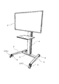
以下、本発明の転倒防止機器の第1実施形態について図面を参照にしながら説明する。ここで、図1は本発明の第1実施形態における転倒防止機器が取り付けられたディスプレイスタンドを示す図である。
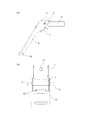
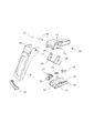
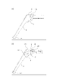
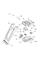
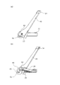
次に、本発明の転倒防止機器の第2実施形態について図面を参照しながら説明する。ここで、本発明の第2実施形態と第1実施形態の異なるところは、第1実施形態の転倒防止機器1では、使用者が足で解除レバー9を操作することにより、転倒防止スタンド8の床面の位置の維持状態を解除するようにしたが、第2実施形態では、使用者が足で解除ボタン42を操作することにより、転倒防止スタンド43の床面の位置の維持状態を解除するようにしたところが異なる。なお、第2実施形態においては、第1実施形態と異なるところを中心に説明する。また、第2実施形態では、第1実施形態と同一構成については、同一符号を用い、同一作用効果を奏するものとし説明は省略する。また、第2実施形態の転倒防止機器41についても、図1で説明したように、ディスプレイ3を支持する脚部2に取り付けられ、ディスプレイ3が転倒しないように支持するために用いられる。ここで、第2実施形態の転倒防止機器41についても、第1実施形態の転倒防止機器1と同様、図1に示すようにディスプレイスタンドの脚部2に取り付けられる。
(変形例1)
上記第2実施形態では、脚部2と脚部結合体7を重ね合わせて接合させたが、変形例1では、脚部2と脚部結合体7の間に脚部接続体33を着脱自在に取り付け、脚部2と脚部結合体7の間に脚部接続体33を挟んで接合させたところが異なる。なお、上述の異なるところ以外については、変形例1と本実施形態は同じであるので、異なるところを中心に説明する。また、変形例1では、説明の便宜上、第2実施形態の図面を用いて説明するが、変形例1は第1実施形態についても適用される。
2 脚部
3 ディスプレイ
4 支柱
5 脚パイプ
6 キャスター
7 脚部結合体
7a 下部脚部結合体
7b 上部脚部結合体
8 転倒防止スタンド
9 解除レバー
10 係止部
11 結合体凸部
12 凸部キャスター螺子挿入孔
13 結合部
14 プラスチック部材
15 長孔
16 移動部材挿入孔
17 移動部材
18 ナット係止具
19 ナット
20 弾性バネ
21 移動部材バネ係止孔
22 脚部結合体バネ係止孔
23 解除レバー支持部
24 スタンド支持孔
25 レバー支持孔
26 回転軸
27 留め具
28 脚部キャスター螺子挿入孔
29 キャスター螺子
30 移動部材支持孔
31 螺子
32 脚部下部取付板
33 脚部接続体
34 接続体キャスター螺子挿入孔
41 転倒防止機器
42 解除ボタン
43 転倒防止スタンド
44 脚部結合体
45 係止部
46 解除ボタン挿入孔
47 解除ボタン中部凸部
48 移動部材上部傾斜部
49 解除ボタン後部凸部
51 移動部材
52 回転軸係止凹部
53 回転軸押圧部
Claims (7)
- 上部媒体を支持する脚部に取り付けられ、該上部媒体が転倒しないように支持する転倒防止機器であって、
前記脚部の端部に設けられた脚部結合体と、
前記脚部結合体の端部近傍と結合し、該結合部を軸として、床面の位置から前記脚部上方の位置まで回動可能で、床面の位置のときには前記脚部結合体の先端から延出する転倒防止スタンドと、
前記転倒防止スタンド上部に設けられ、前記転倒防止スタンドを床面の位置の維持状態にするため前記脚部結合体下部と係止する係止部と、
前記係止部を脚部結合体下部に係止しない状態にし、前記転倒防止スタンドの床面の位置の維持状態を解除する床面状態解除手段と、を有し、
該床面状態解除手段は、使用者の足により操作されることにより、前記転倒防止スタンドの床面の位置の維持状態を解除することを特徴とする転倒防止機器。 - 前記転倒防止スタンドに前記脚部の方向のバネ弾性力を付与する弾性バネと、を有し、
前記脚部結合体は、前記転倒防止スタンドとの結合部に前記脚部方向の長孔が形成され、
前記床面状態解除手段が操作されることにより、前記弾性バネによるバネ弾性力に逆らって、前記転倒防止スタンドが前記脚部結合体の長孔に沿って前記脚部の方向と逆方向に移動し、前記係止部による前記脚部結合体と前記転倒防止スタンドの係止が解かれることにより、前記転倒防止スタンドの床面の位置の維持状態が解除されることを特徴とする請求項1記載の転倒防止機器。 - 前記脚部結合体は、前記脚部の端部に着脱自在に取り付けられることを特徴とする請求項1記載の転倒防止機器。
- 前記転倒防止スタンドは、前記脚部結合体下部を軸として、前記弾性バネによるバネ弾性力に逆らって前記脚部結合体の長孔に沿って移動しながら、前記転倒防止スタンド先端を脚部方向に回動させることができる請求項2記載の転倒防止機器。
- 前記係止部は、前記転倒防止スタンドに一体的に構成されていることを特徴とする請求項1記載の転倒防止機器。
- 前記床面状態解除手段は、前記転倒防止スタンドが床面の位置の状態で前記転倒防止スタンド近傍の前記脚部の方向側で、該転倒防止スタンドの左右側面から延出して設けられている解除レバー、または、前記脚部結合体上部に設けられた解除ボタンであることを特徴とする請求項1記載の転倒防止機器。
- 前記脚部と前記脚部結合体の間に着脱自在に取り付けられる脚部接続体を、さらに有し、
前記脚部端部の形状が異なっていても前記脚部結合体を前記脚部接続体を介して前記脚部に取り付けることができる請求項3記載の転倒防止機器。
Applications Claiming Priority (2)
| Application Number | Priority Date | Filing Date | Title |
|---|---|---|---|
| JP2015069984 | 2015-03-30 | ||
| JP2015069984 | 2015-03-30 |
Publications (2)
| Publication Number | Publication Date |
|---|---|
| JP2016190018A true JP2016190018A (ja) | 2016-11-10 |
| JP6180044B2 JP6180044B2 (ja) | 2017-08-16 |
Family
ID=57245887
Family Applications (1)
| Application Number | Title | Priority Date | Filing Date |
|---|---|---|---|
| JP2015232545A Active JP6180044B2 (ja) | 2015-03-30 | 2015-11-29 | 転倒防止機器 |
Country Status (1)
| Country | Link |
|---|---|
| JP (1) | JP6180044B2 (ja) |
Cited By (1)
| Publication number | Priority date | Publication date | Assignee | Title |
|---|---|---|---|---|
| JP2020003159A (ja) * | 2018-06-29 | 2020-01-09 | ダイキン工業株式会社 | 空気調和装置 |
Families Citing this family (1)
| Publication number | Priority date | Publication date | Assignee | Title |
|---|---|---|---|---|
| CN111297098A (zh) * | 2019-11-25 | 2020-06-19 | 东华大学 | 一种防止柜子倾斜倒塌的装置 |
Citations (5)
| Publication number | Priority date | Publication date | Assignee | Title |
|---|---|---|---|---|
| JPS5028054U (ja) * | 1973-07-10 | 1975-04-01 | ||
| JPH0471504A (ja) * | 1990-07-11 | 1992-03-06 | Matsushita Electric Ind Co Ltd | 電子黒板 |
| JPH08336431A (ja) * | 1995-06-14 | 1996-12-24 | Ebisuya Kogyo Kk | 移動式テーブル等のストッパ装置 |
| JPH10185085A (ja) * | 1996-12-27 | 1998-07-14 | Tec Corp | 黒板用スタンド |
| JP2013043533A (ja) * | 2011-08-24 | 2013-03-04 | Kooei Sangyo Kk | キャスタ付き台車 |
-
2015
- 2015-11-29 JP JP2015232545A patent/JP6180044B2/ja active Active
Patent Citations (5)
| Publication number | Priority date | Publication date | Assignee | Title |
|---|---|---|---|---|
| JPS5028054U (ja) * | 1973-07-10 | 1975-04-01 | ||
| JPH0471504A (ja) * | 1990-07-11 | 1992-03-06 | Matsushita Electric Ind Co Ltd | 電子黒板 |
| JPH08336431A (ja) * | 1995-06-14 | 1996-12-24 | Ebisuya Kogyo Kk | 移動式テーブル等のストッパ装置 |
| JPH10185085A (ja) * | 1996-12-27 | 1998-07-14 | Tec Corp | 黒板用スタンド |
| JP2013043533A (ja) * | 2011-08-24 | 2013-03-04 | Kooei Sangyo Kk | キャスタ付き台車 |
Cited By (1)
| Publication number | Priority date | Publication date | Assignee | Title |
|---|---|---|---|---|
| JP2020003159A (ja) * | 2018-06-29 | 2020-01-09 | ダイキン工業株式会社 | 空気調和装置 |
Also Published As
| Publication number | Publication date |
|---|---|
| JP6180044B2 (ja) | 2017-08-16 |
Similar Documents
| Publication | Publication Date | Title |
|---|---|---|
| US7032922B1 (en) | Stroller with a detachable seat member | |
| JP4757486B2 (ja) | 陳列装置用係合部材 | |
| TWI850798B (zh) | 用於兒童安全座椅之座椅本體之底座結構 | |
| JP6633731B1 (ja) | クランプ装置 | |
| US9254048B2 (en) | Unlocked-state retention device and seat assembly having the same | |
| US7174815B1 (en) | Hand tool with a swinging structure | |
| AU2017245336B2 (en) | Joint assembly for connecting a long extension panel to a patient support panel of a radiation therapy table and a two-piece patient support table formed thereby | |
| JP6180044B2 (ja) | 転倒防止機器 | |
| JP5356678B2 (ja) | 移動机 | |
| JP3155260U (ja) | 折畳み式テーブル | |
| KR20200084474A (ko) | 클램핑 기구 | |
| US11660080B2 (en) | Biopsy gun | |
| JPH11115381A (ja) | 回転黒板 | |
| JP2016070447A (ja) | スタンド | |
| JP5972952B2 (ja) | アームレストのロック解除装置 | |
| JP6732265B1 (ja) | 片脚スタンド型補助輪ユニット及び自転車 | |
| JP7138469B2 (ja) | シャワーフック | |
| JP5460998B2 (ja) | ロッキング装置のロック機構 | |
| JP4136571B2 (ja) | 折り畳み家具のロック装置 | |
| JP2021016546A (ja) | 清掃具 | |
| JP3783441B2 (ja) | 回転黒板 | |
| JPWO2016185588A1 (ja) | 鞄 | |
| JP4153869B2 (ja) | キャスタの旋回規制構造 | |
| JP5356550B2 (ja) | 椅子の肘掛け装置 | |
| JP3118837U (ja) | 学校用机の連結構造及びこれに用いる連結具 |
Legal Events
| Date | Code | Title | Description |
|---|---|---|---|
| A977 | Report on retrieval |
Free format text: JAPANESE INTERMEDIATE CODE: A971007 Effective date: 20170309 |
|
| A131 | Notification of reasons for refusal |
Free format text: JAPANESE INTERMEDIATE CODE: A131 Effective date: 20170511 |
|
| A521 | Request for written amendment filed |
Free format text: JAPANESE INTERMEDIATE CODE: A523 Effective date: 20170626 |
|
| TRDD | Decision of grant or rejection written | ||
| A01 | Written decision to grant a patent or to grant a registration (utility model) |
Free format text: JAPANESE INTERMEDIATE CODE: A01 Effective date: 20170713 |
|
| A61 | First payment of annual fees (during grant procedure) |
Free format text: JAPANESE INTERMEDIATE CODE: A61 Effective date: 20170714 |
|
| R150 | Certificate of patent or registration of utility model |
Ref document number: 6180044 Country of ref document: JP Free format text: JAPANESE INTERMEDIATE CODE: R150 |
|
| R250 | Receipt of annual fees |
Free format text: JAPANESE INTERMEDIATE CODE: R250 |
|
| R250 | Receipt of annual fees |
Free format text: JAPANESE INTERMEDIATE CODE: R250 |
|
| R250 | Receipt of annual fees |
Free format text: JAPANESE INTERMEDIATE CODE: R250 |
|
| R250 | Receipt of annual fees |
Free format text: JAPANESE INTERMEDIATE CODE: R250 |
|
| R250 | Receipt of annual fees |
Free format text: JAPANESE INTERMEDIATE CODE: R250 |
|
| R250 | Receipt of annual fees |
Free format text: JAPANESE INTERMEDIATE CODE: R250 |