JP2016199060A - Vehicular seat - Google Patents

Vehicular seat Download PDF

Info

Publication number
JP2016199060A
JP2016199060A JP2015078196A JP2015078196A JP2016199060A JP 2016199060 A JP2016199060 A JP 2016199060A JP 2015078196 A JP2015078196 A JP 2015078196A JP 2015078196 A JP2015078196 A JP 2015078196A JP 2016199060 A JP2016199060 A JP 2016199060A
Authority
JP
Japan
Prior art keywords
tension
planar member
frame
adjustment
vehicle seat
Prior art date
Legal status (The legal status is an assumption and is not a legal conclusion. Google has not performed a legal analysis and makes no representation as to the accuracy of the status listed.)
Granted
Application number
JP2015078196A
Other languages
Japanese (ja)
Other versions
JP6488837B2 (en
Inventor
秀隆 永安
Hidetaka Nagayasu
秀隆 永安
Current Assignee (The listed assignees may be inaccurate. Google has not performed a legal analysis and makes no representation or warranty as to the accuracy of the list.)
Toyota Boshoku Corp
Original Assignee
Toyota Boshoku Corp
Priority date (The priority date is an assumption and is not a legal conclusion. Google has not performed a legal analysis and makes no representation as to the accuracy of the date listed.)
Filing date
Publication date
Application filed by Toyota Boshoku Corp filed Critical Toyota Boshoku Corp
Priority to JP2015078196A priority Critical patent/JP6488837B2/en
Publication of JP2016199060A publication Critical patent/JP2016199060A/en
Application granted granted Critical
Publication of JP6488837B2 publication Critical patent/JP6488837B2/en
Expired - Fee Related legal-status Critical Current
Anticipated expiration legal-status Critical

Links

Images

Landscapes

  • Chair Legs, Seat Parts, And Backrests (AREA)
  • Seats For Vehicles (AREA)

Abstract

PROBLEM TO BE SOLVED: To enable fine adjustment of tension of a planar member in a vehicular seat for constructing a plane for supporting an occupant by the planar member stretched on a frame.SOLUTION: A vehicular seat 1 includes: a frame 2; a planar member 3 stretched on the frame 2; and tension adjustment means for adjusting tension applied to a prescribed portion of the planar member 3. In the vehicular seat, a plurality of tension adjustment means are arranged side by side in a prescribed direction along the frame 2. It is preferable that the plurality of tension adjustment means are provided symmetrically with respect to at least one of a plane for dividing the frame 2 into two of right and left sides and a symmetry plane for vertically dividing the frame into two.SELECTED DRAWING: Figure 3

Description

本発明は、フレームに張り渡される面状部材によって乗員を支持する面が構築される乗物用シートに関する。   The present invention relates to a vehicle seat in which a surface for supporting an occupant is constructed by a planar member stretched over a frame.

このようなシートが下記特許文献1に開示されている。特許文献1に記載のシート(シートバック)は、フレームに張り渡されるネット部材の張力を、上下方向および左右方向(幅方向)において調整することができるものである。   Such a sheet is disclosed in Patent Document 1 below. The seat (seat back) described in Patent Document 1 can adjust the tension of the net member stretched over the frame in the vertical direction and the horizontal direction (width direction).

特開2012-228899号公報JP 2012-228899 A

上記特許文献1に記載される技術は、左右方向の張力を調整する張力調整手段と、上下方向の張力を調整する張力調整手段がそれぞれ一つずつ設けられたものであるため、乗員の体格等に合わせた細かな調整ができない。例えば、左側を右側に比して張力を高める等、左右または上下非対称の調整ができない。   The technique described in Patent Document 1 includes a tension adjusting unit that adjusts the tension in the left-right direction and a tension adjusting unit that adjusts the tension in the vertical direction. Cannot make fine adjustments to match For example, left-right or up-down asymmetric adjustment cannot be performed, such as increasing the tension from the left side to the right side.

本発明は、フレームに張り渡される面状部材によって乗員を支持する面が構築される乗物用シートにおいて、面状部材の張力の細かな調整を可能とすることを目的とする。   An object of the present invention is to enable fine adjustment of the tension of a planar member in a vehicle seat in which a plane that supports an occupant is constructed by a planar member stretched over a frame.

上記課題を解決するために本発明にかかる乗物用シートは、フレームと、前記フレームに張り渡されている面状部材と、前記面状部材の所定部位に作用する張力を調整する張力調整手段と、を備え、前記張力調整手段は、前記フレームに沿う所定の方向に並んで複数設けられていることを特徴とする。   In order to solve the above problems, a vehicle seat according to the present invention includes a frame, a planar member stretched over the frame, and tension adjusting means for adjusting a tension acting on a predetermined portion of the planar member. The tension adjusting means is provided in a plurality along the predetermined direction along the frame.

前記張力調整手段は、前記フレームを左右に二分する面および上下に二分する対称面の少なくともいずれか一方に関し、対称に設けられているとよい。   The tension adjusting means may be provided symmetrically with respect to at least one of a plane that bisects the frame left and right and a symmetry plane that bisects the frame vertically.

前記張力調整手段は、前記面状部材の所定部位に直接または間接的に接続された部分の位置を変化させることによって、前記面状部材の所定部位に作用する張力を調整するものであるとよい。   The tension adjusting means may adjust the tension acting on the predetermined part of the planar member by changing the position of the part directly or indirectly connected to the predetermined part of the planar member. .

前記張力調整手段は、前記面状部材の所定部位に直接または間接的に接続された部分を、シート後方に設けられた複数の引掛部のうちのいずれに引っ掛けるかによって、前記面状部材の所定部位に作用する張力を調整するものであるとよい。   The tension adjusting means is configured to determine a predetermined portion of the planar member depending on whether a portion directly or indirectly connected to the predetermined portion of the planar member is hooked on any of a plurality of hook portions provided at the rear of the seat. It is good to adjust the tension acting on the part.

本発明にかかる乗物用シートは、フレームに沿う所定の方向に並んで張力調整手段が複数設けられているから、従来に比して面状部材の張力の細かな調整が可能となる。   Since the vehicle seat according to the present invention is provided with a plurality of tension adjusting means arranged in a predetermined direction along the frame, the tension of the planar member can be finely adjusted as compared with the conventional case.

張力調整手段が、フレームを左右に二分する面および上下に二分する面の少なくともいずれか一方に関し対称に設けられていれば、当該対称面に関し、面状部材の張力を均等にすることもできるし、当該対称面の一方側と他方側において張力の差が生じるように設定することもできる。   If the tension adjusting means is provided symmetrically with respect to at least one of the plane bisecting the frame left and right and the plane bisecting up and down, the tension of the planar member can be equalized with respect to the symmetry plane. It is also possible to set so that a difference in tension occurs between one side and the other side of the symmetry plane.

張力調整手段は、面状部材の所定部位に直接または間接的に接続された部分の位置を変化させることによって、面状部材の所定部位に作用する張力を調整するものとすることもできるし、面状部材の所定部位に直接または間接的に接続された部分を複数の引掛部のうちのいずれに引っ掛けるかによって、面状部材の所定部位に作用する張力を調整するものとすることもできる。このような構成とすれば、所定方向に沿って並ぶ複数の張力調整手段を容易に構築することができる。   The tension adjusting means can adjust the tension acting on the predetermined part of the planar member by changing the position of the part directly or indirectly connected to the predetermined part of the planar member, The tension acting on the predetermined portion of the planar member can be adjusted by hooking the portion directly or indirectly connected to the predetermined portion of the planar member to any of the plurality of hooks. With such a configuration, it is possible to easily construct a plurality of tension adjusting means arranged along a predetermined direction.

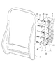
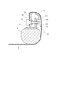
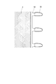
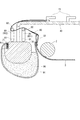
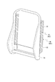
第一実施例にかかる乗物用シートの外観図である。It is an external view of the vehicle seat according to the first embodiment. 図1に示した乗物用シートの(シートバック)を分解して示した図である(フレームの左右方向の一方側に設けられた張力調整手段のみ示し、他方側については左右対称形状であるため省略してある)。FIG. 2 is an exploded view of the (seat back) of the vehicle seat shown in FIG. 1 (only the tension adjusting means provided on one side in the left-right direction of the frame is shown, and the other side is symmetrical) Omitted). 図1に示した乗物用シートの断面を模式的に示した図である。It is the figure which showed typically the cross section of the vehicle seat shown in FIG. (a)は第二実施例にかかる乗物用シートの断面を模式的に示した図である。(b)は引掛部に引掛部材が引っ掛けられた状態を示した図である。(A) is the figure which showed typically the cross section of the vehicle seat concerning a 2nd Example. (B) is the figure which showed the state by which the hook member was hooked by the hook part. 面状部材、中継部材および引掛部材の組体を示した図である。It is the figure which showed the assembly of a planar member, a relay member, and a hook member. 第三実施例にかかる乗物用シートの断面を模式的に示した図である。It is the figure which showed typically the cross section of the vehicle seat concerning a 3rd Example. 第四実施例にかかる乗物用シートの断面を模式的に示した図である。It is the figure which showed typically the cross section of the vehicle seat concerning 4th Example. 第四実施例にかかる乗物用シートのメインフレームと位置規制部材の組体の外観図である。It is an external view of the assembly of the main frame and position control member of the vehicle seat concerning a 4th example.

以下、本発明の実施形態について図面を参照しつつ詳細に説明する。なお、特に明示した場合を除き、以下の説明における前後方向とは乗物用シート1が搭載された乗物の進行・後退方向をいうものとし、上下方向とは当該乗物の上下方向をいうものとし、左右方向(幅方向)とは前後方向および上下方向に直交する方向をいうものとする。なお、特に明示した場合を除き、各方向はシートバック1aが起立した状態にあるときの方向をいうものとする。   Hereinafter, embodiments of the present invention will be described in detail with reference to the drawings. Unless otherwise specified, the front-rear direction in the following description refers to the advancing / retreating direction of the vehicle on which the vehicle seat 1 is mounted, and the up-down direction refers to the up-down direction of the vehicle. The left-right direction (width direction) means a direction orthogonal to the front-rear direction and the up-down direction. Unless otherwise specified, each direction refers to a direction when the seat back 1a is standing.

本実施形態にかかる乗物用シート1は、フレーム2に面状部材3が張り渡されることによって乗員を支持する面が構築されるものである。面状部材3は、フレーム2に張り渡すことができるものであればどのようなものであってもよく、以下の各実施例で示すようなネット(メッシュ)状のものであってもよいし、布状のものであってもよい。以下、乗物用シート1のシートバック1a(背もたれ部)に当該構造が構築されたものとして具体的な構成(第一実施例〜第四実施例)について説明する。   In the vehicle seat 1 according to the present embodiment, a surface that supports an occupant is constructed by the planar member 3 being stretched over the frame 2. The planar member 3 may be any material as long as it can be stretched over the frame 2, and may be a net (mesh) shape as shown in the following embodiments. It may be cloth-like. Hereinafter, a specific configuration (first embodiment to fourth embodiment) will be described on the assumption that the structure is constructed in the seat back 1a (backrest portion) of the vehicle seat 1.

[第一実施例(図1〜図3参照)]
第一実施例にかかる乗物用シートについて説明する。本例にかかる乗物用シートの正面視略方形状のフレーム2には、第一調整部材10が固定されている。第一調整部材10は、硬質の板材が屈曲加工された上下方向に長い部材であって、固定部11、ボルト係止部12、摺動部13を有する。固定部11は、断面で見て左右方向に沿う部分であって、フレーム2に固定する部分である。当該固定部11とフレーム2の接合方法はどのようなものであってもよい。フレーム2と第一調整部材10(固定部11)の両方が金属である場合には、溶接によって両者を接合することができる。
[First embodiment (see FIGS. 1 to 3)]
The vehicle seat according to the first embodiment will be described. The first adjustment member 10 is fixed to the frame 2 having a substantially square shape in front view of the vehicle seat according to this example. The first adjustment member 10 is a member that is long in the up-down direction in which a hard plate material is bent, and includes a fixing portion 11, a bolt locking portion 12, and a sliding portion 13. The fixing portion 11 is a portion that extends in the left-right direction when viewed in cross section, and is a portion that is fixed to the frame 2. Any method may be used for joining the fixing portion 11 and the frame 2. When both the frame 2 and the first adjustment member 10 (fixed portion 11) are metal, they can be joined by welding.

ボルト係止部12は、断面で見て前後方向に沿う部分であって、後述する調整ボルト21が留められる部分である。本例では、上下方向に並ぶ複数の貫通孔121に連通する調整ナット122が固定されており、当該調整ナット122がボルト係止部12となる。摺動部13は、断面で見て、ボルト係止部12から幅方向外側に延び、そこから湾曲して幅方向内側に向かう部分である。   The bolt locking portion 12 is a portion along the front-rear direction as seen in a cross section, and is a portion to which an adjustment bolt 21 described later is fastened. In this example, an adjustment nut 122 communicating with a plurality of through holes 121 arranged in the vertical direction is fixed, and the adjustment nut 122 serves as the bolt locking portion 12. The sliding portion 13 is a portion extending in the width direction outside from the bolt locking portion 12 when viewed in cross section, and curved from there and directed inward in the width direction.

本例にかかる乗物用シートは、第一調整部材10とは別の第二調整部材20を備える。第二調整部材20は、詳細を後述する中継部材30に対し、上下方向に並んで複数設けられ、第一調整部材10のボルト係止部12と対向するように位置する。当該第二調整部材20の数は、上記調整ナット122の数と一致する。上下方向に並ぶ各第二調整部材20間の間隔は、対応する調整ナット122間の間隔と一致する。当該複数の第二調整部材20それぞれには、調整ボルト21が固定されている。各調整ボルト21は、その頭部と固定ナット22との間に第二調整部材20を挟み込むことによって各調整部材に固定されている。各調整ボルト21は、調整ナット122に螺合している。   The vehicle seat according to this example includes a second adjustment member 20 different from the first adjustment member 10. A plurality of second adjustment members 20 are provided side by side in the vertical direction with respect to the relay member 30 described in detail later, and are positioned so as to face the bolt locking portions 12 of the first adjustment member 10. The number of the second adjusting members 20 matches the number of the adjusting nuts 122. The interval between the second adjustment members 20 arranged in the vertical direction coincides with the interval between the corresponding adjustment nuts 122. An adjustment bolt 21 is fixed to each of the plurality of second adjustment members 20. Each adjustment bolt 21 is fixed to each adjustment member by sandwiching the second adjustment member 20 between its head and the fixing nut 22. Each adjustment bolt 21 is screwed to the adjustment nut 122.

中継部材30は布材(例えば綿布)である。各第二調整部材20は、中継部材30の一方側の側縁に沿うように固定されている。中継部材30の他方側の側縁には面状部材3が接続されている。つまり、中継部材30は、各第二調整部材20と面状部材3とを繋ぐ部材である。後述するように、中継部材30が面状部材3に力を伝達することになるが、当該力が中継部材30の伸縮によって吸収されてしまうのを抑制するため、中継部材30を構成する材料はできるだけ伸縮性が低いものであることが望ましい。   The relay member 30 is a cloth material (for example, cotton cloth). Each second adjustment member 20 is fixed along the side edge of one side of the relay member 30. The planar member 3 is connected to the other side edge of the relay member 30. That is, the relay member 30 is a member that connects each second adjustment member 20 and the planar member 3. As will be described later, the relay member 30 transmits a force to the planar member 3, but in order to prevent the force from being absorbed by the expansion and contraction of the relay member 30, the material constituting the relay member 30 is It is desirable that the elasticity is as low as possible.

本例では、このような第一調整部材10や第二調整部材20、中継部材30等が左右両側に設けられている。各部材は、フレーム2を左右に二分する面に関し、対称(左右対称)である。   In this example, the first adjustment member 10, the second adjustment member 20, the relay member 30, and the like are provided on both the left and right sides. Each member is symmetric (left-right symmetric) with respect to a plane that bisects the frame 2 to the left and right.

このように構成される本例にかかる乗物用シートの作用(面状部材3の張力調整作用)は以下の通りである。調整ボルト21を対応する調整ナット122に螺合させることにより、第二調整部材20および中継部材30を介して面状部材3が引っ張られ、当該面状部材3がフレーム2に張り渡された状態となる。面状部材3の張力を調整する際には、いずれかの調整ボルト21の位置を変化させる。つまり、調整ナット122に螺合している調整ボルト21を回転させることにより、調整ボルト21と調整ナット122の距離を変化させる。調整ボルト21を調整ナット122に対して締め込む方向に回転させれば、調整ボルト21が幅方向外側に移動する。そうすると、当該移動させた調整ボルト21に接続された第二調整部材20が幅方向外側に移動するため、当該第二調整部材20に接続された中継部材30を介して面状部材3が緩む。つまり、面状部材3の所定部位(移動させた調整ボルト21が位置する高さの部位)の張力が低下する。一方、調整ボルト21を調整ナット122に対して緩める方向に回転させれば、調整ボルト21が幅方向内側に移動する。そうすると、当該移動させた調整ボルト21に接続された第二調整部材20が幅方向内側に移動するため、当該第二調整部材20に接続された中継部材30を介して面状部材3が引っ張られる。つまり、面状部材3の所定部位(移動させた調整ボルト21が位置する高さの部位)の張力が上昇する。なお、中継部材30は、滑らかな湾曲面を形成する第一調整部材10の摺動部13に接触した状態にあるため、動きはスムーズである。   The action (the tension adjusting action of the planar member 3) of the vehicle seat according to this example configured as described above is as follows. When the adjustment bolt 21 is screwed to the corresponding adjustment nut 122, the planar member 3 is pulled via the second adjustment member 20 and the relay member 30, and the planar member 3 is stretched over the frame 2. It becomes. When adjusting the tension of the planar member 3, the position of any of the adjustment bolts 21 is changed. That is, the distance between the adjustment bolt 21 and the adjustment nut 122 is changed by rotating the adjustment bolt 21 screwed into the adjustment nut 122. If the adjustment bolt 21 is rotated in the direction to be tightened with respect to the adjustment nut 122, the adjustment bolt 21 is moved outward in the width direction. Then, since the second adjustment member 20 connected to the moved adjustment bolt 21 moves outward in the width direction, the planar member 3 is loosened via the relay member 30 connected to the second adjustment member 20. That is, the tension at a predetermined part of the planar member 3 (a part at a height where the moved adjustment bolt 21 is located) is lowered. On the other hand, if the adjustment bolt 21 is rotated in the direction of loosening with respect to the adjustment nut 122, the adjustment bolt 21 moves inward in the width direction. Then, since the second adjustment member 20 connected to the moved adjustment bolt 21 moves inward in the width direction, the planar member 3 is pulled via the relay member 30 connected to the second adjustment member 20. . That is, the tension at a predetermined part of the planar member 3 (a part at a height where the moved adjustment bolt 21 is located) increases. In addition, since the relay member 30 is in the state which contacted the sliding part 13 of the 1st adjustment member 10 which forms a smooth curved surface, a motion is smooth.

このように、本例では、調整ボルト21の位置を変化させることにより、当該調整ボルト21に間接的に(第二調整部材20や中継部材30を介して)接続された面状部材3の所定部位の張力を増減させることができる。そして、このような張力調整手段は、フレーム2の上下方向に延びる部分に沿って複数設けられているため、面状部材3の上下方向における細やかな張力の調整が可能となる。また、張力調整手段が、フレーム2を左右に二分する面に関し対称に設けられているため、左右の面状部材3の張力を均等にすることもできるし、左側と右側において張力の差が生じるように設定することもできる。   Thus, in this example, by changing the position of the adjustment bolt 21, the planar member 3 connected to the adjustment bolt 21 indirectly (via the second adjustment member 20 or the relay member 30) is predetermined. The tension of the part can be increased or decreased. And since such a tension adjusting means is provided with two or more along the part extended in the up-down direction of the flame | frame 2, the tension | tensile_strength adjustment in the up-down direction of the planar member 3 is attained. Further, since the tension adjusting means is provided symmetrically with respect to the plane that bisects the frame 2 left and right, the tension of the left and right planar members 3 can be equalized, and a difference in tension occurs between the left side and the right side. It can also be set as follows.

[第二実施例(図4、図5参照)]
第二実施例にかかる乗物用シートについて、上記第一実施例と異なる点を中心に説明する。本例にかかる乗物用シートは、バックボード40、中継部材50および引掛部材60を備える。バックボード40は、フレーム2の後方に橋渡しするように固定された板状の部材であって、シートバックの後面を構築する。フレーム2とバックボード40の固定方法はどのようなものであってもよい。バックボード40には、引掛部41が形成されている。
[Second embodiment (see FIGS. 4 and 5)]
The vehicle seat according to the second embodiment will be described focusing on differences from the first embodiment. The vehicle seat according to this example includes a backboard 40, a relay member 50, and a hooking member 60. The back board 40 is a plate-like member fixed so as to be bridged behind the frame 2 and constructs the rear surface of the seat back. Any method may be used for fixing the frame 2 and the backboard 40. A hook 41 is formed on the backboard 40.

引掛部41は、引掛部材60が引っ掛けられることができるものであればどのような構造、形状であってもよい。本例では、基端側から幅方向内側に向かう鉤状の部分である。当該引掛部41は、幅方向かつ上下方向に複数並ぶように設けられている。当該引掛部41は、フレーム2を左右に二分する面に関し対称に設けられている。幅方向に並ぶ引掛部41の数、上下方向に並ぶ引掛部41の数は適宜変更可能である。また、幅方向に並ぶ引掛部41同士の間隔や、上下方向に並ぶ引掛部41同士の間隔は同じ(等間隔)であってもよいし、異なっていてもよい。また、本例では、上下方向に引掛部41が直線状に並んでいるが、直線状にならんでいなくてもよい。例えば、ある高さに位置する引掛部41のうち最も幅方向外側に位置するものと、それとは別の高さに位置する引掛部41のうち最も幅方向外側に位置するものの、幅方向における位置が異なっていてもよい。   The hook portion 41 may have any structure and shape as long as the hook member 60 can be hooked. In this example, it is a bowl-shaped part which goes inward in the width direction from the base end side. A plurality of the hooking portions 41 are arranged in the width direction and the vertical direction. The hook 41 is provided symmetrically with respect to a plane that bisects the frame 2 to the left and right. The number of hooks 41 arranged in the width direction and the number of hooks 41 arranged in the vertical direction can be changed as appropriate. Further, the interval between the hooking portions 41 arranged in the width direction and the interval between the hooking portions 41 arranged in the vertical direction may be the same (equal intervals) or may be different. Further, in this example, the hooks 41 are arranged in a straight line in the vertical direction, but may not be in a straight line. For example, the position in the width direction of the hook portion 41 located at the outermost position in the width direction among the hook portions 41 located at a certain height and the position of the hook portion 41 located at the outermost position in the width direction different from that. May be different.

中継部材50は布材(例えば綿布)である。後述するように、中継部材50が面状部材3に力を伝達することになるが、当該力が中継部材50の伸縮によって吸収されてしまうのを抑制するため、中継部材50を構成する材料はできるだけ伸縮性が低いものであることが望ましい。かかる中継部材50の一方側に面状部材3が接続されている。中継部材50の他方側には、複数の引掛部材60が接続されている。本実施形態では、布材を折り返した部分が中継部材50の他方側に位置し、当該折り返した部分に上下方向に並ぶ複数の切れ込みを形成することによって生じた複数の断面略U字状の部分のそれぞれに紐状の引掛部材60が引っ掛けられている。   The relay member 50 is a cloth material (for example, cotton cloth). As will be described later, the relay member 50 transmits a force to the planar member 3, but in order to prevent the force from being absorbed by the expansion and contraction of the relay member 50, the material constituting the relay member 50 is It is desirable that the elasticity is as low as possible. The planar member 3 is connected to one side of the relay member 50. A plurality of hook members 60 are connected to the other side of the relay member 50. In the present embodiment, the portion where the cloth material is folded is located on the other side of the relay member 50, and a plurality of substantially U-shaped cross-section portions are generated by forming a plurality of cuts arranged in the vertical direction in the folded portion. A string-like hooking member 60 is hooked on each of these.

紐状の引掛部材60は、全体として環状を呈する。かかる引掛部材60を構成する材料についても、中継部材50と同様の理由から、伸縮性が低いものであることが望ましい。上下方向に並ぶ引掛部材60の数は、上下方向に並ぶ引掛部41の数(幅方向に並ぶ引掛部41を一つと考えた場合の引掛部41の数)と同じである。   The string-like hooking member 60 has an annular shape as a whole. The material constituting the hook member 60 is also preferably low in elasticity for the same reason as the relay member 50. The number of hook members 60 arranged in the vertical direction is the same as the number of hook parts 41 arranged in the vertical direction (the number of hook parts 41 when the number of hook parts 41 arranged in the width direction is considered as one).

このように構成される本例にかかる乗物用シートの作用(面状部材3の張力調整作用)は以下の通りである。各引掛部材60を、対応する高さに位置し、幅方向に並ぶ複数の引掛部41のうちのいずれかに引っ掛けることにより、フレーム2に対し面状部材3が張り渡された状態となる。面状部材3の張力を調整する際には、引掛部材60が引っ掛けられる引掛部41を変化させる。引掛部材60を当該時点で引っ掛けられている引掛部41よりも幅方向外側に位置する引掛部41に引っ掛ければ、中継部材50を介して面状部材3を引っ張る力が弱くなるため、面状部材3が緩む。つまり、面状部材3の所定部位(引っ掛ける引掛部41の位置を変化させた引掛部材60が位置する高さの部位)の張力が低下する。一方、引掛部材60を当該時点で引っ掛けられている引掛部41よりも幅方向内側に位置する引掛部41に引っ掛ければ、中継部材50を介して面状部材3を引っ張る力が強くなるため、面状部材3が引っ張られる。つまり、面状部材3の所定部位(引っ掛ける引掛部41の位置を変化させた引掛部材60が位置する高さの部位)の張力が上昇する。   The action (the tension adjusting action of the planar member 3) of the vehicle seat according to this example configured as described above is as follows. Each of the hook members 60 is located at a corresponding height and hooked on any one of the plurality of hook portions 41 arranged in the width direction, whereby the planar member 3 is stretched over the frame 2. When the tension of the planar member 3 is adjusted, the hooking portion 41 to which the hooking member 60 is hooked is changed. If the hooking member 60 is hooked on the hooking portion 41 located on the outer side in the width direction than the hooking portion 41 hooked at that time, the force for pulling the planar member 3 via the relay member 50 is weakened. The member 3 is loosened. That is, the tension at a predetermined part of the planar member 3 (a part at a height where the hooking member 60 where the position of the hooking part 41 to be hooked is changed) is lowered. On the other hand, if the hook member 60 is hooked on the hook portion 41 located on the inner side in the width direction than the hook portion 41 hooked at that time, the force for pulling the planar member 3 via the relay member 50 is increased. The planar member 3 is pulled. That is, the tension of a predetermined portion of the planar member 3 (a portion at a height where the hooking member 60 where the position of the hooking portion 41 to be hooked is changed) is increased.

このように、本例では、引掛部材60が引っ掛けられる引掛部41の位置を幅方向に変化させることにより、当該引掛部材60に間接的に(中継部材50を介して)接続された面状部材3の所定部位の張力を増減させることができる。そして、このような張力調整手段は、フレーム2の上下方向に延びる部分に沿って複数設けられているため、面状部材3の上下方向における細やかな張力の調整が可能となる。また、張力調整手段が、フレーム2を左右に二分する面に関し対称に設けられているため、左右の面状部材3の張力を均等にすることもできるし、左側と右側において張力の差が生じるように設定することもできる。   Thus, in this example, the planar member connected indirectly to the hooking member 60 (via the relay member 50) by changing the position of the hooking portion 41 to which the hooking member 60 is hooked in the width direction. It is possible to increase or decrease the tension at the predetermined portion 3. And since such a tension adjusting means is provided with two or more along the part extended in the up-down direction of the flame | frame 2, the tension | tensile_strength adjustment in the up-down direction of the planar member 3 is attained. Further, since the tension adjusting means is provided symmetrically with respect to the plane that bisects the frame 2 left and right, the tension of the left and right planar members 3 can be equalized, and a difference in tension occurs between the left side and the right side. It can also be set as follows.

[第三実施例(図6参照)・第四実施例(図7、図8参照)]
第三実施例・第四実施例にかかる乗物用シートについて、上記第一実施例・第二実施例と異なる点を中心に説明する。第三実施例・第四実施例にかかる乗物用シートは、面状部材3が張り渡されるフレーム2とは別のフレーム(メインフレーム70と称する)を備えているものである。
[Third embodiment (see FIG. 6) / Fourth embodiment (see FIGS. 7 and 8)]
The vehicle seat according to the third embodiment and the fourth embodiment will be described focusing on differences from the first embodiment and the second embodiment. The vehicle seat according to the third and fourth embodiments includes a frame (referred to as a main frame 70) different from the frame 2 on which the planar member 3 is stretched.

第三実施例は、張力調整手段による面状部材3の張力調整機構の基本的な部分は第一実施例と同じである(いわば、第三実施例は第一実施例の変形例である)。第一調整部材10は、メインフレーム70に固定されている。第一調整部材10および第二調整部材20(調整ボルト21や調整ナット122を含む)、中継部材30の構成は同じである。   In the third embodiment, the basic part of the tension adjusting mechanism of the planar member 3 by the tension adjusting means is the same as that of the first embodiment (in other words, the third embodiment is a modification of the first embodiment). . The first adjustment member 10 is fixed to the main frame 70. The configurations of the first adjustment member 10, the second adjustment member 20 (including the adjustment bolt 21 and the adjustment nut 122), and the relay member 30 are the same.

中継部材30に接続された面状部材3は、メインフレーム70より内側に位置するフレーム2に張り渡されている。つまり、本例では、第一調整部材10が支持される部材(メインフレーム70)と、面状部材3が張り渡される部材が異なる。調整ボルト21を幅方向内側に移動させると、面状部材3の所定部位(移動させた調整ボルト21が位置する高さの部位)の張力が低下する。調整ボルト21を幅方向外側に移動させると、面状部材3の所定部位(移動させた調整ボルト21が位置する高さの部位)の張力が上昇する。つまり、本例と第一実施例と比較すると、調整ボルト21の移動によって面状部材3の張力を増減するということでは共通するが、調整ボルト21の移動方向(幅方向内側または外側)と、面状部材3の張力の増減の関係は逆である。   The planar member 3 connected to the relay member 30 is stretched over the frame 2 located inside the main frame 70. That is, in this example, the member (main frame 70) on which the first adjustment member 10 is supported is different from the member on which the planar member 3 is stretched. When the adjustment bolt 21 is moved inward in the width direction, the tension at a predetermined portion of the planar member 3 (a portion at a height where the moved adjustment bolt 21 is located) is lowered. When the adjustment bolt 21 is moved outward in the width direction, the tension at a predetermined portion of the planar member 3 (a portion at a height where the moved adjustment bolt 21 is located) increases. That is, compared with this example and the first embodiment, it is common to increase or decrease the tension of the planar member 3 by the movement of the adjustment bolt 21, but the movement direction of the adjustment bolt 21 (in the width direction inside or outside), The relation of increase / decrease in the tension of the planar member 3 is opposite.

なお、本例では、メインフレーム70を覆うクッション材であるパッド90が設けられている。パッド90は、パッドカバー91に覆われており当該パッドカバー91が中継部材30に接続されている。本例では、パッドカバー91の中継部材30に接続された反対側の端部は、固定部材911を介してメインフレーム70に固定されている。具体的には、メインフレーム70には嵌合溝71が形成されており、当該嵌合溝71内に固定部材911が嵌合されている。このように、中継部材30には、面状部材3とパッドカバー91が接続されている。したがって、調整ボルト21の位置が変化したとき、中継部材30を介して、面状部材3だけでなくパッドカバー91に対する張力も変化することとなるが、中継部材30を介した力の少なくとも一部は面状部材3に伝達されるため、調整ボルト21の位置の変化によって面状部材3の張力が増減することに変わりはない。   In this example, a pad 90 which is a cushion material covering the main frame 70 is provided. The pad 90 is covered with a pad cover 91, and the pad cover 91 is connected to the relay member 30. In this example, the opposite end of the pad cover 91 connected to the relay member 30 is fixed to the main frame 70 via a fixing member 911. Specifically, a fitting groove 71 is formed in the main frame 70, and a fixing member 911 is fitted in the fitting groove 71. Thus, the planar member 3 and the pad cover 91 are connected to the relay member 30. Therefore, when the position of the adjustment bolt 21 changes, the tension on the pad cover 91 as well as the planar member 3 changes via the relay member 30, but at least a part of the force via the relay member 30 is changed. Is transmitted to the planar member 3, the tension of the planar member 3 is increased or decreased by the change in the position of the adjusting bolt 21.

第四実施例は、張力調整手段による面状部材3の張力調整機構の基本的な部分は第二実施例と同じである(いわば、第四実施例は第二実施例の変形例である)。メインフレーム70には、二つの位置規制部材80(第一位置規制部材801および第二位置規制部材802)が固定されている。位置規制部材80は、例えば金属製の棒状が図示されるように曲げ加工されてなる。位置規制部材80は、その上側および下側に位置するメインフレーム70に接続される接続部81と、接続部81の間の部分である規制部82とを有する。接続部81がメインフレーム70に接続された状態において、規制部82はメインフレームの後方に位置する。具体的には、第一位置規制部材801の規制部82と、第二位置規制部材802の規制部82がメインフレーム70の後方で幅方向に並んで位置する。   In the fourth embodiment, the basic part of the tension adjusting mechanism of the planar member 3 by the tension adjusting means is the same as that of the second embodiment (in other words, the fourth embodiment is a modification of the second embodiment). . Two position restricting members 80 (a first position restricting member 801 and a second position restricting member 802) are fixed to the main frame 70. The position restricting member 80 is formed by bending, for example, a metal bar shape as shown in the figure. The position restricting member 80 includes a connecting portion 81 connected to the main frame 70 positioned on the upper side and the lower side thereof, and a restricting portion 82 that is a portion between the connecting portions 81. In a state where the connecting portion 81 is connected to the main frame 70, the restricting portion 82 is located behind the main frame. Specifically, the restricting portion 82 of the first position restricting member 801 and the restricting portion 82 of the second position restricting member 802 are positioned side by side in the width direction behind the main frame 70.

バックボード40は、メインフレーム70に固定されている。本例では、バックボード40の周縁部分が前方に向かって突出しており、当該部分が第一位置規制部材801の規制部82と、第二位置規制部材802の規制部82の間に位置する。バックボード40の当該部分には、引掛部材60を通すための溝が形成されている。バックボード40には上記第一実施例と同様の引掛部41が形成されている。   The backboard 40 is fixed to the main frame 70. In this example, the peripheral portion of the backboard 40 protrudes forward, and the portion is located between the restriction portion 82 of the first position restriction member 801 and the restriction portion 82 of the second position restriction member 802. A groove for passing the hooking member 60 is formed in the portion of the backboard 40. The backboard 40 is formed with a hooking portion 41 similar to that in the first embodiment.

引掛部材60は、中継部材50側から見て、幅方向内側に位置する第一規制部材の規制部82の後方を通り、そこから幅方向外側に位置する第二規制部材の規制部82の前方を通ってUターンするようにしてバックボード40の後方に至り、いずれかの引掛部41に引っ掛けられる。   When viewed from the relay member 50 side, the hooking member 60 passes behind the restricting portion 82 of the first restricting member located on the inner side in the width direction and forward of the restricting portion 82 of the second restricting member located on the outer side in the width direction therefrom. The U-turn is passed through to the rear of the backboard 40 and is hooked on one of the catch portions 41.

引掛部材60を当該時点で引っ掛けられている引掛部41よりも幅方向外側に位置する引掛部41に引っ掛ければ、面状部材3の所定部位(引っ掛ける引掛部41の位置を変化させた引掛部材60が位置する高さの部位)の張力が低下する。一方、引掛部材60を当該時点で引っ掛けられている引掛部41よりも幅方向内側に位置する引掛部41に引っ掛ければ、面状部材3の所定部位(引っ掛ける引掛部41の位置を変化させた引掛部材60が位置する高さの部位)の張力が上昇する。   If the hooking member 60 is hooked on the hooking portion 41 located on the outer side in the width direction than the hooking portion 41 hooked at that time, a predetermined portion of the planar member 3 (the hooking member in which the position of the hooking portion 41 to be hooked is changed) The tension at the height of 60 is reduced. On the other hand, if the hooking member 60 is hooked on the hooking portion 41 located on the inner side in the width direction than the hooking portion 41 hooked at that time, the predetermined portion of the planar member 3 (the position of the hooking portion 41 to be hooked is changed). The tension at the height of the hook member 60 is increased.

なお、本例においても、第三実施例と同様、メインフレーム70を覆うクッション材であるパッド90が設けられている。パッド90は、パッドカバー91に覆われており当該パッドカバー91が中継部材50に接続されている。パッドカバー91の中継部材30に接続された反対側の端部は、固定部材911を介してメインフレーム70に固定されている。具体的には、メインフレーム70には嵌合溝71が形成されており、当該嵌合溝71内に固定部材911が嵌合されている。このように、中継部材50には、面状部材3とパッドカバー91が接続されている。したがって、引掛部材60が引っ掛けられる引掛部41を変えたとき、中継部材50を介して、面状部材3だけでなくパッドカバー91に対する張力も変化することとなるが、中継部材50を介した力の少なくとも一部は面状部材3に伝達されるため、引っ掛けられる引掛部41が変わったことによって面状部材3の張力が増減することに変わりはない。   In this example as well, as in the third example, a pad 90, which is a cushion material covering the main frame 70, is provided. The pad 90 is covered with a pad cover 91, and the pad cover 91 is connected to the relay member 50. The opposite end of the pad cover 91 connected to the relay member 30 is fixed to the main frame 70 via a fixing member 911. Specifically, a fitting groove 71 is formed in the main frame 70, and a fixing member 911 is fitted in the fitting groove 71. Thus, the planar member 3 and the pad cover 91 are connected to the relay member 50. Therefore, when the hooking portion 41 to which the hooking member 60 is hooked is changed, not only the planar member 3 but also the tension on the pad cover 91 is changed via the relay member 50, but the force via the relay member 50 is changed. Since at least a part of is transmitted to the planar member 3, the tension of the planar member 3 increases or decreases when the hooking portion 41 to be hooked is changed.

以上、本発明の実施形態について詳細に説明したが、本発明は上記実施形態に何ら限定されるものではなく、本発明の要旨を逸脱しない範囲で種々の改変が可能である。   As mentioned above, although embodiment of this invention was described in detail, this invention is not limited to the said embodiment at all, A various change is possible in the range which does not deviate from the summary of this invention.

上記実施形態(各実施例)にかかる乗物用シート1は、左右方向(幅方向)における面状部材3の張力を調整するため、上下方向に沿って複数の張力調整手段が設けられたものであることを説明したが、上下方向における面状部材3の張力を調整するための構成として、上記と同様の構成を設けてもよい。つまり、左右方向に沿って複数の張力調整手段を設けた構成としてもよい。この場合、フレーム2の上側にのみ左右方向に並ぶ複数の張力調整手段を設けた構成としてもよい。また、フレーム2の上側および下側に沿って並ぶ複数の張力調整手段を設ける構成とする場合、面状部材3の張力のバランスを均等にすることができるよう、上下に二分する対称面方に関し、対称に設けられているとよい。   The vehicle seat 1 according to the embodiment (each example) is provided with a plurality of tension adjusting means along the vertical direction in order to adjust the tension of the planar member 3 in the horizontal direction (width direction). As described above, a configuration similar to the above may be provided as a configuration for adjusting the tension of the planar member 3 in the vertical direction. That is, it is good also as a structure which provided the several tension adjustment means along the left-right direction. In this case, a plurality of tension adjusting means arranged in the left-right direction only on the upper side of the frame 2 may be provided. Further, when a plurality of tension adjusting means arranged along the upper side and the lower side of the frame 2 are provided, a symmetrical plane that bisects up and down so that the balance of the tension of the planar member 3 can be made uniform. It is good to be provided symmetrically.

そして、上記実施形態(各実施例)で説明した上下方向に並ぶ複数の張力調整手段が設けられた構成と、左右方向に沿って複数の張力調整手段が並べられた構成の両方が適用された一の乗物用シートとしてもよい。   And both the structure provided with the several tension adjustment means arranged in the up-down direction demonstrated in the said embodiment (each Example) and the structure where the several tension adjustment means were arranged along the left-right direction were applied. It may be a single vehicle seat.

上記実施形態(各実施例)にかかる乗物用シート1は、フレーム2に張り渡される面状部材3が中継部材30、50等を介して複数の張力調整手段に接続されたものであるが、このような中継部材30、50等を用いず、面状部材3が直接張力調整手段に接続された構造としてもよい。   In the vehicle seat 1 according to the above-described embodiment (each example), the planar member 3 stretched over the frame 2 is connected to a plurality of tension adjusting means via the relay members 30, 50, etc. A structure in which the planar member 3 is directly connected to the tension adjusting means without using the relay members 30 and 50 and the like may be used.

上記実施形態(各実施例)は、面状部材3の張力調整手段が設けられたシートバック1aについて説明したが、同様の構成を乗物用シート1のシートクッション(座部)や、ヘッドレスト、アームレスト等に適用することも可能である。つまり、乗員を支持するものについて、同様の技術思想が適用可能である。   Although the said embodiment (each Example) demonstrated the seat back 1a provided with the tension | tensile_strength adjustment means of the planar member 3, the seat cushion (seat part) of the vehicle seat 1, a headrest, an armrest is the same structure. It is also possible to apply to the above. That is, the same technical idea can be applied to those that support the passenger.

1 乗物用シート
1a シートバック
2 フレーム
3 面状部材
10 第一調整部材
20 第二調整部材
30 中継部材
40 バックボード
41 引掛部
50 中継部材
60 引掛部材
DESCRIPTION OF SYMBOLS 1 Vehicle seat 1a Seat back 2 Frame 3 Planar member 10 1st adjustment member 20 2nd adjustment member 30 Relay member 40 Backboard 41 Hook part 50 Relay member 60 Hook member

Claims (4)

フレームと、
前記フレームに張り渡されている面状部材と、
前記面状部材の所定部位に作用する張力を調整する張力調整手段と、
を備え、
前記張力調整手段は、前記フレームに沿う所定の方向に並んで複数設けられていることを特徴とする乗物用シート。
Frame,
A planar member stretched over the frame;
Tension adjusting means for adjusting tension acting on a predetermined portion of the planar member;
With
The vehicle seat according to claim 1, wherein a plurality of the tension adjusting means are provided side by side in a predetermined direction along the frame.
前記張力調整手段は、前記フレームを左右に二分する面および上下に二分する対称面の少なくともいずれか一方に関し、対称に設けられていることを特徴とする請求項1に記載の乗物用シート。   2. The vehicle seat according to claim 1, wherein the tension adjusting means is provided symmetrically with respect to at least one of a plane that bisects the frame left and right and a symmetry plane that bisects the frame vertically. 前記張力調整手段は、前記面状部材の所定部位に直接または間接的に接続された部分の位置を変化させることによって、前記面状部材の所定部位に作用する張力を調整するものであることを特徴とする請求項1または請求項2に記載の乗物用シート。   The tension adjusting means adjusts the tension acting on the predetermined part of the planar member by changing the position of the part directly or indirectly connected to the predetermined part of the planar member. The vehicle seat according to claim 1, wherein the vehicle seat is a vehicle seat. 前記張力調整手段は、前記面状部材の所定部位に直接または間接的に接続された部分を、シート後方に設けられた複数の引掛部のうちのいずれに引っ掛けるかによって、前記面状部材の所定部位に作用する張力を調整するものであることを特徴とする請求項1または請求項2に記載の乗物用シート。
The tension adjusting means is configured to determine a predetermined portion of the planar member depending on whether a portion directly or indirectly connected to the predetermined portion of the planar member is hooked on any of a plurality of hook portions provided at the rear of the seat. The vehicle seat according to claim 1 or 2, wherein a tension acting on the part is adjusted.
JP2015078196A 2015-04-07 2015-04-07 Vehicle seat Expired - Fee Related JP6488837B2 (en)

Priority Applications (1)

Application Number Priority Date Filing Date Title
JP2015078196A JP6488837B2 (en) 2015-04-07 2015-04-07 Vehicle seat

Applications Claiming Priority (1)

Application Number Priority Date Filing Date Title
JP2015078196A JP6488837B2 (en) 2015-04-07 2015-04-07 Vehicle seat

Publications (2)

Publication Number Publication Date
JP2016199060A true JP2016199060A (en) 2016-12-01
JP6488837B2 JP6488837B2 (en) 2019-03-27

Family

ID=57422139

Family Applications (1)

Application Number Title Priority Date Filing Date
JP2015078196A Expired - Fee Related JP6488837B2 (en) 2015-04-07 2015-04-07 Vehicle seat

Country Status (1)

Country Link
JP (1) JP6488837B2 (en)

Cited By (1)

* Cited by examiner, † Cited by third party
Publication number Priority date Publication date Assignee Title
JP2020059303A (en) * 2018-10-05 2020-04-16 トヨタ自動車株式会社 Vehicle seat

Citations (5)

* Cited by examiner, † Cited by third party
Publication number Priority date Publication date Assignee Title
JPS5934658U (en) * 1982-08-27 1984-03-03 立川スプリング株式会社 Seat with variable support
JPH10502836A (en) * 1994-07-20 1998-03-17 ヘンダーソンズ・インダストリーズ・ピーテイワイ・リミテツド Waist support adjustment device
US20020190562A1 (en) * 2001-06-14 2002-12-19 Tornero Marta V. Furniture structure and method
JP2012183755A (en) * 2011-03-07 2012-09-27 Toyota Boshoku Corp Apparatus and method for manufacturing supporting member
JP2014097226A (en) * 2012-11-15 2014-05-29 Quali:Kk Backrest structure for chair

Patent Citations (5)

* Cited by examiner, † Cited by third party
Publication number Priority date Publication date Assignee Title
JPS5934658U (en) * 1982-08-27 1984-03-03 立川スプリング株式会社 Seat with variable support
JPH10502836A (en) * 1994-07-20 1998-03-17 ヘンダーソンズ・インダストリーズ・ピーテイワイ・リミテツド Waist support adjustment device
US20020190562A1 (en) * 2001-06-14 2002-12-19 Tornero Marta V. Furniture structure and method
JP2012183755A (en) * 2011-03-07 2012-09-27 Toyota Boshoku Corp Apparatus and method for manufacturing supporting member
JP2014097226A (en) * 2012-11-15 2014-05-29 Quali:Kk Backrest structure for chair

Cited By (2)

* Cited by examiner, † Cited by third party
Publication number Priority date Publication date Assignee Title
JP2020059303A (en) * 2018-10-05 2020-04-16 トヨタ自動車株式会社 Vehicle seat
JP7294786B2 (en) 2018-10-05 2023-06-20 トヨタ自動車株式会社 vehicle seat

Also Published As

Publication number Publication date
JP6488837B2 (en) 2019-03-27

Similar Documents

Publication Publication Date Title
JP7269519B2 (en) seat frame
JP5989706B2 (en) Vehicle seat
US11299119B2 (en) Vehicle seat
JP6284583B2 (en) Vehicle seat
US10239561B2 (en) Side collision load transmission structure
US11046222B2 (en) Fatigue reducing seat
JP5988578B2 (en) Sheet
US10604043B2 (en) Seat frame
JP6488837B2 (en) Vehicle seat
JP6863234B2 (en) Vehicle seat
JP6364309B2 (en) Sheet
WO2018029896A1 (en) Vehicle seat
CN103847538A (en) Vehicle Seats
JP2014100941A (en) Vehicle seat
JP5733936B2 (en) Vehicle seat
JP6593291B2 (en) Vehicle seat
JP2015020597A (en) Vehicle seat structure
JP7707058B2 (en) Seat back frame and vehicle seat
JP6513724B2 (en) Vehicle seat
JP6931178B2 (en) Seat frame
JP2021094997A5 (en)
JP2014212976A (en) Vehicular seat
JP2019112011A (en) Vehicle seat
WO2019026957A1 (en) Reinforcement structure for seat frame
JP7091631B2 (en) Vehicle seat

Legal Events

Date Code Title Description
A621 Written request for application examination

Free format text: JAPANESE INTERMEDIATE CODE: A621

Effective date: 20171124

A977 Report on retrieval

Free format text: JAPANESE INTERMEDIATE CODE: A971007

Effective date: 20180820

A131 Notification of reasons for refusal

Free format text: JAPANESE INTERMEDIATE CODE: A131

Effective date: 20180828

A521 Request for written amendment filed

Free format text: JAPANESE INTERMEDIATE CODE: A523

Effective date: 20180926

TRDD Decision of grant or rejection written
A01 Written decision to grant a patent or to grant a registration (utility model)

Free format text: JAPANESE INTERMEDIATE CODE: A01

Effective date: 20190129

A61 First payment of annual fees (during grant procedure)

Free format text: JAPANESE INTERMEDIATE CODE: A61

Effective date: 20190211

R151 Written notification of patent or utility model registration

Ref document number: 6488837

Country of ref document: JP

Free format text: JAPANESE INTERMEDIATE CODE: R151

LAPS Cancellation because of no payment of annual fees