JP2016199193A - Visor device for vehicle - Google Patents
Visor device for vehicle Download PDFInfo
- Publication number
- JP2016199193A JP2016199193A JP2015082160A JP2015082160A JP2016199193A JP 2016199193 A JP2016199193 A JP 2016199193A JP 2015082160 A JP2015082160 A JP 2015082160A JP 2015082160 A JP2015082160 A JP 2015082160A JP 2016199193 A JP2016199193 A JP 2016199193A
- Authority
- JP
- Japan
- Prior art keywords
- visor
- frame elements
- support member
- frame
- vehicle
- Prior art date
- Legal status (The legal status is an assumption and is not a legal conclusion. Google has not performed a legal analysis and makes no representation as to the accuracy of the status listed.)
- Pending
Links
Images




Landscapes
- Fittings On The Vehicle Exterior For Carrying Loads, And Devices For Holding Or Mounting Articles (AREA)
Abstract
【課題】バイザに力を加えてバイザを回動させる場合であっても、バイザが捩れることを抑制できる、車両用バイザ装置の提供。【解決手段】装置10は、支持部材20と、バイザ30と、フレーム40と、を有する。バイザ30は、本体部31と、本体部31から支持部材20側に突出する突出部32と、突出部32に形成される回動軸部33と、を備えており、回動軸部33にて支持部材20に回動軸芯AXまわりに回動可能に支持されている。フレーム40は、バイザ30より高剛性の第1、第2のフレーム要素41,42を備えており、第1、第2のフレーム要素41,42にてバイザ30の突出部32を挟み込んでいる。第1、第2のフレーム要素41,42にてバイザ30の突出部32を挟み込むため、バイザ30に力を加えてバイザ30を回動させる場合であっても、バイザ30が捩れることを抑制できる。【選択図】 図3An object of the present invention is to provide a vehicle visor device capable of suppressing twisting of the visor even when the visor is rotated by applying a force to the visor. An apparatus includes a support member, a visor, and a frame. The visor 30 includes a main body portion 31, a protruding portion 32 protruding from the main body portion 31 toward the support member 20, and a rotating shaft portion 33 formed on the protruding portion 32. The support member 20 is supported so as to be rotatable about the rotation axis AX. The frame 40 includes first and second frame elements 41 and 42 having higher rigidity than the visor 30, and the protruding portion 32 of the visor 30 is sandwiched between the first and second frame elements 41 and 42. Since the protruding portion 32 of the visor 30 is sandwiched between the first and second frame elements 41 and 42, the visor 30 is prevented from being twisted even when the visor 30 is rotated by applying a force to the visor 30. it can. [Selection] Figure 3
Description
本発明は、車両用のバイザ(サンバイザ)装置に関する。 The present invention relates to a visor (sun visor) device for a vehicle.
特開平11−342738号公報は、バイザと、バイザの回動軸を構成するシャフトと、バイザの片側のみに配置されるモータと、を有し、モータからの力をシャフトの一端部に加えることでバイザを上下方向に回動させる技術を開示している。 Japanese Patent Application Laid-Open No. 11-342738 has a visor, a shaft constituting a rotating shaft of the visor, and a motor arranged only on one side of the visor, and applies a force from the motor to one end of the shaft. Discloses a technique for rotating the visor vertically.
一般的に、バイザは比較的低剛性である。そのため、シャフトではなくバイザに力を加えてバイザを上下方向に回動させる場合、バイザに捩れが発生することがある。そのため、(a)バイザを円滑に回動させることが難しい、(b)バイザの回動時に異音が発生する、(c)バイザ(の回動軸部)が破損する、等のおそれがある。 In general, the visor is relatively low in rigidity. Therefore, when a force is applied to the visor instead of the shaft to rotate the visor in the vertical direction, the visor may be twisted. Therefore, there is a possibility that (a) it is difficult to rotate the visor smoothly, (b) abnormal noise is generated when the visor is rotated, (c) the visor (its rotation shaft portion) is damaged, etc. .
本発明の目的は、バイザに力を加えてバイザを回動させる場合であっても、バイザが捩れることを抑制できる、車両用バイザ装置を提供することにある。 An object of the present invention is to provide a vehicle visor device that can suppress twisting of the visor even when the visor is rotated by applying a force to the visor.
上記目的を達成する本発明はつぎの通りである。
(1)支持部材と、バイザと、フレームと、を有し、
前記バイザは、本体部と、該本体部から前記支持部材側に突出する突出部と、該突出部の突出方向先端部に形成される回動軸部と、を備えており、該回動軸部にて前記支持部材に回動軸芯まわりに上下方向に回動可能に支持されており、
前記フレームは、前記バイザより高剛性の第1、第2のフレーム要素を備えており、該第1、第2のフレーム要素にて前記バイザの突出部を前記バイザの厚み方向の両側から挟み込んでいる、
車両用バイザ装置。
(2) 電動駆動機構を、さらに有しており、
前記電動駆動機構は、前記第1、第2のフレーム要素の少なくとも一方に力を加えることで、前記バイザを、前記支持部材に対して前記回動軸芯まわりに上下方向に回動させており、
前記第1、第2のフレーム要素は、前記バイザの前記回動軸芯の延びる方向に前記バイザの全体にわたって延びて設けられており、
前記電動駆動機構は、前記第1、第2のフレーム要素の前記少なくとも一方の延び方向一端部に力を加える、(1)記載の車両用バイザ装置。
The present invention for achieving the above object is as follows.
(1) having a support member, a visor, and a frame;
The visor includes a main body portion, a protruding portion that protrudes from the main body portion toward the support member, and a rotating shaft portion that is formed at a leading end portion in the protruding direction of the protruding portion. Is supported by the support member so as to be pivotable in the vertical direction around the pivot axis,
The frame includes first and second frame elements having higher rigidity than the visor, and the protruding portions of the visor are sandwiched from both sides in the thickness direction of the visor by the first and second frame elements. Yes,
Vehicle visor device.
(2) It further has an electric drive mechanism,
The electric drive mechanism applies a force to at least one of the first and second frame elements to rotate the visor up and down around the rotation axis with respect to the support member. ,
The first and second frame elements are provided to extend over the entire visor in a direction in which the pivot axis of the visor extends.
The vehicle visor device according to (1), wherein the electric drive mechanism applies a force to one end portion in the extending direction of the at least one of the first and second frame elements.
上記(1)の車両用バイザ装置によれば、バイザより高剛性の第1、第2のフレーム要素にてバイザの突出部をバイザの厚み方向の両側から挟み込むため、バイザに力を加えてバイザを回動させる場合であっても、バイザが捩れることを抑制できる。 According to the visor device for a vehicle of the above (1), the visor protrudes from both sides in the thickness direction of the visor with the first and second frame elements having rigidity higher than that of the visor. Even when rotating the visor, it is possible to suppress the visor from being twisted.
上記(2)の車両用バイザ装置によれば、第1、第2のフレーム要素が、バイザの回動軸芯の延びる方向にバイザの全体にわたって延びて設けられているため、バイザの回動軸芯の延びる方向の全体にわたってバイザの捩れを抑制できる。
また、電動駆動機構が、第1、第2のフレーム要素の少なくとも一方の延び方向一端部に力を加えるため、電動駆動機構をバイザの回動軸芯の延びる方向でバイザの片側に配置でき、車両用バイザ装置のコンパクト化を図る点において有利である。
According to the vehicle visor device of the above (2), the first and second frame elements are provided so as to extend over the entire visor in the direction in which the rotation axis of the visor extends. The twist of the visor can be suppressed over the entire extending direction of the core.
In addition, since the electric drive mechanism applies a force to at least one extending direction one end portion of the first and second frame elements, the electric drive mechanism can be arranged on one side of the visor in the direction in which the rotation axis of the visor extends, This is advantageous in reducing the size of the vehicle visor device.
以下に、本発明実施例の車両用バイザ装置(以下、単にバイザ装置または装置ともいう)を、図面を参照して、説明する。なお、図において、FRは車両前方を示し、UPは上方を示す。 Hereinafter, a visor device for a vehicle according to an embodiment of the present invention (hereinafter also simply referred to as a visor device or a device) will be described with reference to the drawings. In the figure, FR indicates the front of the vehicle and UP indicates the upper side.
本発明実施例の車両用バイザ装置10は、図1に示すように、車室天井1の車両前側端部またはその近傍で、運転席および/または助手席の車両前方に設けられる。バイザ装置10は、主として車両の前席(運転席、助手席)に着座している乗員Pの遮光のために設けられる。バイザ装置10は、図2、図3に示すように、支持部材20と、バイザ30と、フレーム40と、電動駆動機構50と、を有する。
As shown in FIG. 1, a
支持部材20は、車両に固定されるケース21と、ケース21に車両前後方向にスライド可能に支持されるスライダ22と、を備える。スライダ22は、ケース21に対して、図示略の電動機構を用いてまたは手動で往復直線動可能とされている。
The
支持部材20は、図1に示すように、たとえば、ルーフパネル2とルーフヘッドライニング3との間の収納スペースSに配設される。なお、図1において符号4は、フロントガラスである。ルーフヘッドライニング3の前端部には、バイザ30が挿通する開口3aが形成されている。スライダ22にバイザ30が回動可能に取付けられている。支持部材20は、バイザ30を、少なくともバイザ30が鉛直方向に延びる姿勢となる鉛直位置30a(図1の(a))と該鉛直位置30aから車両前方かつ上方に回動してフロントガラス4に略沿う姿勢となる上方位置30b(図1の(b))とに、回動可能に支持する。
As shown in FIG. 1, the
バイザ30は、板状(略板状を含む)である。バイザ30は、部品点数削減のため一部品構成であることが望ましい。バイザ30は、光不透過性樹脂製であってもよく、光透過率が1パーセント以上で99パーセント以下の半透明樹脂製であってもよい。バイザ30は、半透明樹脂製である場合、例えばアクリル樹脂、ポリカーボネート樹脂製である。
The
バイザ30は、図3に示すように、本体部31と、本体部31から支持部材20側に突出する突出部32と、突出部32の突出方向先端部に形成される回動軸部33と、を備える。バイザ30は、回動軸部33にて、支持部材20に、上下方向に回動可能に支持される。バイザ30は、支持部材20に、たとえば図示略のトルクヒンジを用いて、車両左右方向(装置10の幅方向、バイザ30の幅方向)に延びる回動軸芯AXまわりに上下方向に回動可能に支持される。
As shown in FIG. 3, the
本体部31は、1つのみ設けられている。本体部31によって乗員Pの遮光効果を得ることができる。突出部32は、回動軸芯AXの延びる方向に、1つのみ設けられていてもよく、図示例のように複数(図示例では5つ)設けられていてもよい。突出部32が複数設けられる場合、各突出部32の大きさは同じであってもよく、異なっていてもよい。回動軸部33は、突出部32の突出方向先端部とその近傍から支持部材20側に突出している。回動軸部33は、回動軸芯AXの延びる方向に複数設けられている。
Only one
フレーム40は、バイザ30の剛性を高めるために設けられる。フレーム40は、第1、第2のフレーム要素41,42を備える。第1、第2のフレーム要素41,42は、それぞれ、一部品構成である。第1、第2のフレーム要素41は、バイザ30より高剛性の材料で作製されており、たとえば金属製である。ただし、第1、第2のフレーム要素41,42は、金属製に限定されるものではなく、ガラス繊維強化樹脂製等であってもよい。第1、第2のフレーム要素41,42は、回動軸芯AXの延びる方向にバイザ30の全体にわたって連続して延びて設けられている。第1、第2のフレーム要素41,42は、図7に示すように、スクリュ60を用いて互いに固定されている。
The
図8に示すように、第1、第2のフレーム要素41,42にて、バイザ30の突出部32がバイザ30の厚み方向の両側から挟み込まれている。このため、第1、第2のフレーム要素41,42とバイザ30は、一体化され(組付固定され)、一体的に支持部20に対して回動軸芯AXまわりに回動する。
As shown in FIG. 8, the
バイザ30の突出部32のみが第1、第2のフレーム要素41,42によって挟み込まれており、バイザ30の本体部31と回動軸部33は第1、第2のフレーム要素41,42によって挟み込まれていない。バイザ30の本体部31が挟み込まれていないため、フレーム40が設けられている場合であっても、バイザ30の意匠性を確保できる。また、バイザ30の回動軸部33が挟み込まれていないため、バイザ30を支持部材20に対して容易に回動させることができる。
Only the protruding
電動駆動機構50は、図5、図6に示すように、バイザ30を、支持部材20に対して回動軸芯AXまわりに上下方向に回動させる機構である。電動駆動機構50により、バイザ30の角度は調節可能である。
As shown in FIGS. 5 and 6, the
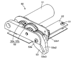
電動駆動機構50は、第1、第2のフレーム要素41,42の少なくとも一方に力を加えることで、バイザ30を回動軸芯AXまわりに回動させる(バイザ30の角度調整をする)機構である。なお、以下、本発明実施例および図示例では、電動駆動機構50が第2のフレーム要素42のみに力を加える場合を説明する。電動駆動機構50は、図3に示すように、モータ51と、モータ51によって回転する少なくとも1つのギア52と、ギア52の動きを第2のフレーム要素42の延び方向一端部のみに伝える伝達部53と、を備える。
The
モータ51とギア52は、図4に示すように、ともに、支持部材20にスクリュ61を用いて固定して取付けられるブラケット62に取付けられている。モータ51は、ブラケット62に固定して取付けられており、ギア52は、ブラケット62に回動可能に取付けられている。ギア52は、たとえば、モータ51によって回転される出力ギア52a、出力ギア52aと噛み合う段付きギア(減速ギア)52bと、からなる。
As shown in FIG. 4, the
伝達部53は、段付きギア52bと噛み合うギア部53a1を備えブラケット62に回動可能に取付けられる伝達ギア53aと、図3に示すように、第2のフレーム要素42の延び方向一端部から第2のフレーム要素42の延び方向と直交する方向に延びる伝達アーム53bと、を備える。
The
伝達ギア53aは、図4に示すように、伝達ギア53aの径方向外側に膨出する膨出部53a2と、膨出部53a2に形成されており伝達ギア53aの径方向を長手方向とする長溝53a3と、を備える。伝達アーム53bは、図3に示すように、伝達アーム53bの延び方向先端部またはその近傍に形成されており伝達ギア53aの長溝53a3に挿入される挿入突起53b1を備える。
As shown in FIG. 4, the
モータ51が駆動したとき、ギア52がモータ51の駆動力によって回転し伝達部53の伝達ギア53aが回転する。伝達ギア53aが回転すると、伝達アーム53bが伝達ギア53aの長溝53a3に挿入される挿入突起53b1を備えるため、挿入突起53b1が長溝53a3の縁によって押される。この結果、モータ51からの力が第2のフレーム要素42の延び方向一端部のみに伝わり、第2のフレーム要素42、第1のフレーム要素41およびバイザ30が一体となって回動軸芯AXまわりに回動する。
When the
つぎに、本発明実施例の作用、効果を説明する。
本発明実施例では、バイザ30より高剛性の第1、第2のフレーム要素41,42にてバイザ30の突出部32をバイザ30の厚み方向の両側から挟み込むため、バイザ30に力を加えてバイザ30を回動させる場合であっても、バイザ30が捩れることを抑制できる。
Next, the operation and effect of the embodiment of the present invention will be described.
In the embodiment of the present invention, the first and
第1、第2のフレーム要素41,42が、バイザ30の回動軸芯AXの延びる方向にバイザ30の全体にわたって延びて設けられているため、バイザ30の回動軸芯AXの延びる方向の全体にわたってバイザ30の捩れを抑制できる。
Since the first and
電動駆動機構50が、第1、第2のフレーム要素41,42の少なくとも一方の延び方向一端部に力を加えるため、電動駆動機構50をバイザ30の回動軸芯AXの延びる方向でバイザ30の片側に配置でき、車両用バイザ装置10の上下方向及び前後方向のコンパクト化を図る点において有利である。
Since the
本発明実施例では、電動駆動機構50を用いて電動でバイザ30を回動させる場合を説明したが、コスト低減のために電動駆動機構50を設けずに手動でバイザ30を回動させてもよい。
In the embodiment of the present invention, the case where the
1 車室天井
2 ルーフパネル
3 ルーフヘッドライニング
3a 開口
4 フロントガラス
10 車両用バイザ装置
20 支持部材
21 ケース
22 スライダ
30 バイザ
31 本体部
32 突出部
33 回動軸部
40 フレーム
41 第1のフレーム要素
42 第2のフレーム要素
50 電動駆動機構
51 モータ
52 ギア
52a 出力ギア
52b 段付きギア
53 伝達部
53a 伝達ギア
53b 伝達アーム
AX バイザの回動軸芯
P 乗員
S スペース
DESCRIPTION OF SYMBOLS 1
Claims (2)
前記バイザは、本体部と、該本体部から前記支持部材側に突出する突出部と、該突出部の突出方向先端部に形成される回動軸部と、を備えており、該回動軸部にて前記支持部材に回動軸芯まわりに上下方向に回動可能に支持されており、
前記フレームは、前記バイザより高剛性の第1、第2のフレーム要素を備えており、該第1、第2のフレーム要素にて前記バイザの突出部を前記バイザの厚み方向の両側から挟み込んでいる、
車両用バイザ装置。 A support member, a visor, and a frame;
The visor includes a main body portion, a protruding portion that protrudes from the main body portion toward the support member, and a rotating shaft portion that is formed at a leading end portion in the protruding direction of the protruding portion. Is supported by the support member so as to be pivotable in the vertical direction around the pivot axis,
The frame includes first and second frame elements having higher rigidity than the visor, and the protruding portions of the visor are sandwiched from both sides in the thickness direction of the visor by the first and second frame elements. Yes,
Vehicle visor device.
前記電動駆動機構は、前記第1、第2のフレーム要素の少なくとも一方に力を加えることで、前記バイザを、前記支持部材に対して前記回動軸芯まわりに上下方向に回動させており、
前記第1、第2のフレーム要素は、前記バイザの前記回動軸芯の延びる方向に前記バイザの全体にわたって延びて設けられており、
前記電動駆動機構は、前記第1、第2のフレーム要素の前記少なくとも一方の延び方向一端部に力を加える、請求項1記載の車両用バイザ装置。
An electric drive mechanism,
The electric drive mechanism applies a force to at least one of the first and second frame elements to rotate the visor up and down around the rotation axis with respect to the support member. ,
The first and second frame elements are provided to extend over the entire visor in a direction in which the pivot axis of the visor extends.
The vehicle visor device according to claim 1, wherein the electric drive mechanism applies a force to one end portion in the extending direction of the at least one of the first and second frame elements.
Priority Applications (1)
| Application Number | Priority Date | Filing Date | Title |
|---|---|---|---|
| JP2015082160A JP2016199193A (en) | 2015-04-14 | 2015-04-14 | Visor device for vehicle |
Applications Claiming Priority (1)
| Application Number | Priority Date | Filing Date | Title |
|---|---|---|---|
| JP2015082160A JP2016199193A (en) | 2015-04-14 | 2015-04-14 | Visor device for vehicle |
Publications (1)
| Publication Number | Publication Date |
|---|---|
| JP2016199193A true JP2016199193A (en) | 2016-12-01 |
Family
ID=57422252
Family Applications (1)
| Application Number | Title | Priority Date | Filing Date |
|---|---|---|---|
| JP2015082160A Pending JP2016199193A (en) | 2015-04-14 | 2015-04-14 | Visor device for vehicle |
Country Status (1)
| Country | Link |
|---|---|
| JP (1) | JP2016199193A (en) |
Citations (4)
| Publication number | Priority date | Publication date | Assignee | Title |
|---|---|---|---|---|
| DE2737215A1 (en) * | 1976-09-23 | 1978-04-06 | Iao Industrie Riunite Spa | SUN VISOR, IN PARTICULAR FOR VEHICLES |
| JPS53105225U (en) * | 1977-01-31 | 1978-08-24 | ||
| JPH0565021A (en) * | 1991-03-09 | 1993-03-19 | Gebr Happich Gmbh | Sunvisor for automobile |
| JP2002144868A (en) * | 2000-11-07 | 2002-05-22 | Neoex Lab Inc | Sun visor for vehicle |
-
2015
- 2015-04-14 JP JP2015082160A patent/JP2016199193A/en active Pending
Patent Citations (4)
| Publication number | Priority date | Publication date | Assignee | Title |
|---|---|---|---|---|
| DE2737215A1 (en) * | 1976-09-23 | 1978-04-06 | Iao Industrie Riunite Spa | SUN VISOR, IN PARTICULAR FOR VEHICLES |
| JPS53105225U (en) * | 1977-01-31 | 1978-08-24 | ||
| JPH0565021A (en) * | 1991-03-09 | 1993-03-19 | Gebr Happich Gmbh | Sunvisor for automobile |
| JP2002144868A (en) * | 2000-11-07 | 2002-05-22 | Neoex Lab Inc | Sun visor for vehicle |
Similar Documents
| Publication | Publication Date | Title |
|---|---|---|
| JP5233283B2 (en) | Vehicle seat with monitor | |
| JP6253937B2 (en) | Vehicle seat | |
| JP5050793B2 (en) | Sun visor device for vehicle | |
| US8511735B2 (en) | Panoramic roof apparatus for vehicle | |
| EP2327576A1 (en) | Automobile roof structure | |
| JP6282384B2 (en) | Opening / closing unit for vehicle inner trim | |
| JP5950779B2 (en) | Automotive electronics | |
| JP2018020731A (en) | Vehicular seat | |
| US20160288631A1 (en) | Dual drive sunroof transmission assembly | |
| JP7024484B2 (en) | In-vehicle transparent display device | |
| JP5109674B2 (en) | Lifter lever arrangement structure for vehicle seat | |
| JP5076685B2 (en) | Vehicle seat | |
| JP2016199193A (en) | Visor device for vehicle | |
| WO2016147372A1 (en) | Display device | |
| US20060066129A1 (en) | JR dashboard shader | |
| JP2011057121A (en) | Sun visor and method for manufacturing the same | |
| KR101261159B1 (en) | multi-plate lumbar support of seat back for automobile | |
| JP7131404B2 (en) | vehicle display | |
| JP6543513B2 (en) | Vehicle visor device | |
| KR101490771B1 (en) | Tilting apparatus of electric mirror for a vehicle | |
| JP6433352B2 (en) | Vehicle visor device | |
| JP2007210553A (en) | Vehicle panel members | |
| JP4380621B2 (en) | In-vehicle display device | |
| JP6671890B2 (en) | Window regulator | |
| JP4900034B2 (en) | Tilt and shade panel device |
Legal Events
| Date | Code | Title | Description |
|---|---|---|---|
| A621 | Written request for application examination |
Free format text: JAPANESE INTERMEDIATE CODE: A621 Effective date: 20180329 |
|
| A977 | Report on retrieval |
Free format text: JAPANESE INTERMEDIATE CODE: A971007 Effective date: 20190124 |
|
| A131 | Notification of reasons for refusal |
Free format text: JAPANESE INTERMEDIATE CODE: A131 Effective date: 20190129 |
|
| A521 | Request for written amendment filed |
Free format text: JAPANESE INTERMEDIATE CODE: A523 Effective date: 20190328 |
|
| A711 | Notification of change in applicant |
Free format text: JAPANESE INTERMEDIATE CODE: A711 Effective date: 20190401 |
|
| A521 | Request for written amendment filed |
Free format text: JAPANESE INTERMEDIATE CODE: A821 Effective date: 20190401 |
|
| A131 | Notification of reasons for refusal |
Free format text: JAPANESE INTERMEDIATE CODE: A131 Effective date: 20190423 |
|
| A02 | Decision of refusal |
Free format text: JAPANESE INTERMEDIATE CODE: A02 Effective date: 20191105 |