JP2016524930A - Self-injection actuator - Google Patents
Self-injection actuator Download PDFInfo
- Publication number
- JP2016524930A JP2016524930A JP2016520183A JP2016520183A JP2016524930A JP 2016524930 A JP2016524930 A JP 2016524930A JP 2016520183 A JP2016520183 A JP 2016520183A JP 2016520183 A JP2016520183 A JP 2016520183A JP 2016524930 A JP2016524930 A JP 2016524930A
- Authority
- JP
- Japan
- Prior art keywords
- coil spring
- actuator unit
- spring
- actuator
- pressure pin
- Prior art date
- Legal status (The legal status is an assumption and is not a legal conclusion. Google has not performed a legal analysis and makes no representation as to the accuracy of the status listed.)
- Granted
Links
Images



Classifications
-
- A—HUMAN NECESSITIES
- A61—MEDICAL OR VETERINARY SCIENCE; HYGIENE
- A61M—DEVICES FOR INTRODUCING MEDIA INTO, OR ONTO, THE BODY; DEVICES FOR TRANSDUCING BODY MEDIA OR FOR TAKING MEDIA FROM THE BODY; DEVICES FOR PRODUCING OR ENDING SLEEP OR STUPOR
- A61M5/00—Devices for bringing media into the body in a subcutaneous, intra-vascular or intramuscular way; Accessories therefor, e.g. filling or cleaning devices, arm-rests
- A61M5/178—Syringes
- A61M5/31—Details
- A61M5/32—Needles; Details of needles pertaining to their connection with syringe or hub; Accessories for bringing the needle into, or holding the needle on, the body; Devices for protection of needles
- A61M5/3202—Devices for protection of the needle before use, e.g. caps
- A61M5/3204—Needle cap remover, i.e. devices to dislodge protection cover from needle or needle hub, e.g. deshielding devices
-
- A—HUMAN NECESSITIES
- A61—MEDICAL OR VETERINARY SCIENCE; HYGIENE
- A61M—DEVICES FOR INTRODUCING MEDIA INTO, OR ONTO, THE BODY; DEVICES FOR TRANSDUCING BODY MEDIA OR FOR TAKING MEDIA FROM THE BODY; DEVICES FOR PRODUCING OR ENDING SLEEP OR STUPOR
- A61M5/00—Devices for bringing media into the body in a subcutaneous, intra-vascular or intramuscular way; Accessories therefor, e.g. filling or cleaning devices, arm-rests
- A61M5/178—Syringes
- A61M5/20—Automatic syringes, e.g. with automatically actuated piston rod, with automatic needle injection, filling automatically
- A61M5/2033—Spring-loaded one-shot injectors with or without automatic needle insertion
-
- A—HUMAN NECESSITIES
- A61—MEDICAL OR VETERINARY SCIENCE; HYGIENE
- A61M—DEVICES FOR INTRODUCING MEDIA INTO, OR ONTO, THE BODY; DEVICES FOR TRANSDUCING BODY MEDIA OR FOR TAKING MEDIA FROM THE BODY; DEVICES FOR PRODUCING OR ENDING SLEEP OR STUPOR
- A61M5/00—Devices for bringing media into the body in a subcutaneous, intra-vascular or intramuscular way; Accessories therefor, e.g. filling or cleaning devices, arm-rests
- A61M5/178—Syringes
- A61M5/20—Automatic syringes, e.g. with automatically actuated piston rod, with automatic needle injection, filling automatically
- A61M2005/2006—Having specific accessories
- A61M2005/202—Having specific accessories cocking means, e.g. to bias the main drive spring of an injector
-
- A—HUMAN NECESSITIES
- A61—MEDICAL OR VETERINARY SCIENCE; HYGIENE
- A61M—DEVICES FOR INTRODUCING MEDIA INTO, OR ONTO, THE BODY; DEVICES FOR TRANSDUCING BODY MEDIA OR FOR TAKING MEDIA FROM THE BODY; DEVICES FOR PRODUCING OR ENDING SLEEP OR STUPOR
- A61M5/00—Devices for bringing media into the body in a subcutaneous, intra-vascular or intramuscular way; Accessories therefor, e.g. filling or cleaning devices, arm-rests
- A61M5/178—Syringes
- A61M5/20—Automatic syringes, e.g. with automatically actuated piston rod, with automatic needle injection, filling automatically
- A61M2005/206—With automatic needle insertion
-
- A—HUMAN NECESSITIES
- A61—MEDICAL OR VETERINARY SCIENCE; HYGIENE
- A61M—DEVICES FOR INTRODUCING MEDIA INTO, OR ONTO, THE BODY; DEVICES FOR TRANSDUCING BODY MEDIA OR FOR TAKING MEDIA FROM THE BODY; DEVICES FOR PRODUCING OR ENDING SLEEP OR STUPOR
- A61M5/00—Devices for bringing media into the body in a subcutaneous, intra-vascular or intramuscular way; Accessories therefor, e.g. filling or cleaning devices, arm-rests
- A61M5/178—Syringes
- A61M5/20—Automatic syringes, e.g. with automatically actuated piston rod, with automatic needle injection, filling automatically
- A61M2005/2073—Automatic syringes, e.g. with automatically actuated piston rod, with automatic needle injection, filling automatically preventing premature release, e.g. by making use of a safety lock
Landscapes
- Health & Medical Sciences (AREA)
- Vascular Medicine (AREA)
- Engineering & Computer Science (AREA)
- Anesthesiology (AREA)
- Biomedical Technology (AREA)
- Heart & Thoracic Surgery (AREA)
- Hematology (AREA)
- Life Sciences & Earth Sciences (AREA)
- Animal Behavior & Ethology (AREA)
- General Health & Medical Sciences (AREA)
- Public Health (AREA)
- Veterinary Medicine (AREA)
- Infusion, Injection, And Reservoir Apparatuses (AREA)
- Fuel-Injection Apparatus (AREA)
Abstract
本発明は、自己注射器のための作動装置ユニットであって、軸方向に移動可能な圧力ピン(4)が案内されている実質的に円筒形のハウジング(3)を備え、前記圧力ピンがばねユニットに逆行して挿入可能とされ、かつ挿入時に、圧力ピンに接続される保持部(5)の戻り止め突起(6)によってロック可能とされている、作動装置ユニットに関する。ばねユニットが、第1のコイルばね(1)と、第1のコイルばねよりも大きい直径を有する少なくとも1つの第2のコイルばね(2)とを備え、第2のコイルばねが第1のコイルばねに対して同軸である。【選択図】図1The present invention comprises an actuator unit for a self-injector comprising a substantially cylindrical housing (3) in which an axially movable pressure pin (4) is guided, said pressure pin being a spring The present invention relates to an actuator unit that can be inserted backward to the unit and that can be locked by a detent protrusion (6) of a holding part (5) connected to a pressure pin at the time of insertion. The spring unit comprises a first coil spring (1) and at least one second coil spring (2) having a larger diameter than the first coil spring, wherein the second coil spring is the first coil. It is coaxial to the spring. [Selection] Figure 1
Description
本発明は、自己注射器のための作動装置ユニットであって、軸方向に移動可能な圧力ピンが案内されている実質的に円筒形のハウジングを備え、前記圧力ピンがばねユニットに抗して挿入可能とされ、かつ挿入時に、圧力ピンに接続される保持部の戻り止め突起によってロック可能とされている、作動装置ユニットに関する。本発明はまた、作動装置ユニットを備える自己注射器に関する。 The invention is an actuator unit for a self-injector comprising a substantially cylindrical housing in which an axially movable pressure pin is guided, said pressure pin being inserted against a spring unit The present invention relates to an actuator unit which can be locked by a detent protrusion of a holding part connected to a pressure pin when inserted. The invention also relates to a self-injector comprising an actuator unit.
冒頭に言及したタイプの作動装置は、簡単かつ自動的に操作され、また主に単回使用向けあり得る医療用皮下注射器の構成要素として使用される。自己注射器と呼ばれるこのようなシリンジは、自己注射器の遠位端が人体の関心領域上にくるように配置され、次いで、多くの場合、自己注射器の近位領域において、簡単な手動操作で始動される。「近位」及び「遠位」の語は、自己注射器の使用者の視点を指す。 Actuators of the type mentioned at the beginning are easily and automatically operated and are mainly used as components of medical hypodermic syringes that may be intended for a single use. Such a syringe, called an auto-injector, is placed so that the distal end of the auto-injector is on the region of interest of the human body, and then often started with a simple manual operation in the proximal region of the auto-injector. The The terms “proximal” and “distal” refer to the viewpoint of the user of the auto-injector.
国際公開第2005/021070(A1)号には、注射液を自動注射するための装置が示されている。前記装置はまた、内部でピストンロッドがばねで押され得る、円筒形のハウジング内にある作動装置を備える。ばねを始動し、続いて、作動装置の遠位端に向けてピストンロッドを押し出すと、カートリッジが注射針に接続され、自動注射のために針が装置から押し出され、ピストンロッドをカートリッジ内に押し込んで、液状の薬剤が針から注射されるようにする。任意で、カートリッジに針を予め接続していてもよい。この教示の不利な点は、作動装置のエネルギー蓄圧器がコイルばねで作られていることである。その結果、液体を注射するのに要する力をかけることができるのは、自動注射プロセスの終わり、すなわち、コイルばねがほぼ弛緩状態にある場合だけとなる。得られる力は、カニューレを通して液状の薬剤を押すのに十分である。しかしながら、カニューレを通して粘性のある薬剤を押す、及び/または直径のより小さいカニューレ通して薬剤を押すにはもはや十分ではない。 WO 2005/021070 (A1) shows a device for automatically injecting an injection solution. The device also comprises an actuating device in a cylindrical housing in which the piston rod can be spring-loaded. Triggering the spring and subsequently pushing the piston rod towards the distal end of the actuator will connect the cartridge to the injection needle, push the needle out of the device for automatic injection, and push the piston rod into the cartridge The liquid drug is injected from the needle. Optionally, a needle may be pre-connected to the cartridge. A disadvantage of this teaching is that the energy accumulator of the actuator is made of a coil spring. As a result, the force required to inject the liquid can only be applied at the end of the automatic injection process, i.e. when the coil spring is in a substantially relaxed state. The resulting force is sufficient to push the liquid drug through the cannula. However, it is no longer sufficient to push a viscous drug through a cannula and / or push a drug through a smaller diameter cannula.
本発明の目的は、薬剤を注射する際により大きい力をかける、冒頭に言及した作動装置を提供することである。加えて、作動装置は、従来技術の作動装置よりも製造するのに複雑さや費用を大幅に増すものであるべきではなく、従来技術の作動装置よりも操作が容易かつ安全でもあるべきであり、外寸が大きくなるべきではない。さらなる目的は、自己注射器の操作を、患者にとって一層快適なものにすることである。 The object of the present invention is to provide an actuator as mentioned at the outset, which applies a greater force when injecting a medicament. In addition, the actuator should not be significantly more complex and expensive to manufacture than prior art actuators, and should be easier and safer to operate than prior art actuators, The outside dimensions should not be large. A further object is to make the operation of the self-injector more comfortable for the patient.
本発明による作動装置は、ばねユニットが、第1のコイルばねと、第1のコイルばねよりも大きい直径を有する少なくとも1つの第2のコイルばねとを備え、第2のコイルばねが第1のコイルばねに対して同軸であるという点で、この目的を達成する。ピストンから作動装置の近位端まで延びるピストンロッドは、もはや設けていない。 In the actuating device according to the present invention, the spring unit includes a first coil spring and at least one second coil spring having a larger diameter than the first coil spring, and the second coil spring is the first coil spring. This objective is achieved in that it is coaxial with the coil spring. There is no longer a piston rod extending from the piston to the proximal end of the actuator.
作動装置ユニットの好適な実施形態は、第1のコイルばね及び第2のコイルばねが実質的に同じ長さを有することを特徴とする。 A preferred embodiment of the actuator unit is characterized in that the first coil spring and the second coil spring have substantially the same length.
本発明の一実施形態では、第1のコイルばね及び第2のコイルばねは、一体の二重ばねの部品として設計される。 In one embodiment of the invention, the first coil spring and the second coil spring are designed as an integral double spring part.
本発明のさらなる実施形態では、第2のコイルばねは、第1のコイルばねによって動かすことができる部品により保持かつロックされ、第1のコイルばねが外側解除点にある場合に、第2のコイルばねのロックを解除できる。 In a further embodiment of the invention, the second coil spring is held and locked by a part that can be moved by the first coil spring, and the second coil spring is when the first coil spring is at the outer release point. The spring can be unlocked.
本発明の別の実施形態では、第1のコイルばねは、第2のコイルばねによって動かすことができる部品により保持かつロックされ、第2のコイルばねが外側解除点にある場合に、第1のコイルばねのロックを解除できる。 In another embodiment of the invention, the first coil spring is held and locked by a part that can be moved by the second coil spring, and the first coil spring is in the outer release point when the first coil spring is at the outer release point. The coil spring can be unlocked.
本発明の一実施形態では、作動装置ユニットは、好適には、軸方向に動かすことができる作動装置スリーブを備え、作動装置スリーブによって、ロックが解除されるように戻り止め突起を変位させることができ、ばねユニットによって圧力ピンを動かすことができる。 In one embodiment of the invention, the actuator unit preferably comprises an actuator sleeve that can be moved axially, by which the detent protrusion can be displaced so that the lock is released. The pressure pin can be moved by the spring unit.
本発明による装置の実施形態では、さらに、作動装置ユニットが、戻り止め突起を所定の場所に固定する部品を含む取り外し可能な安全キャップを備えることが好ましい。 In an embodiment of the device according to the invention, it is further preferred that the actuator unit comprises a removable safety cap that includes parts that secure the detent protrusion in place.
本発明の一実施形態では、作動装置ユニットは、注射器ユニットに接続することができるねじ山またはバヨネットロックをその遠位端に備える。 In one embodiment of the invention, the actuator unit comprises a thread or bayonet lock at its distal end that can be connected to the syringe unit.
本発明の一実施形態では、圧力ピンは、好適には、封を切るための機械的手段をその遠位端面に有する。 In one embodiment of the present invention, the pressure pin preferably has mechanical means on its distal end face for breaking the seal.
本発明はまた、本発明による作動装置ユニットを含む自己注射器に関する。 The invention also relates to a self-injector comprising an actuator unit according to the invention.
以下、図示の実施形態を参照しながら本発明をより詳細に説明する。 Hereinafter, the present invention will be described in more detail with reference to the illustrated embodiments.
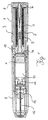
図1によれば、自己注射器は、その遠位端に注射ユニット9を備える。前記注射ユニットの内部には、薬剤を収容するカートリッジ11と、針12とが配置されている。カートリッジ11は、その遠位端において、カートリッジシール16によって密閉されている。カートリッジ11は、その近位端において、カートリッジ内へと動かすことができる圧力ピン4を備える。針12は、針ホルダ13によって保持される。作動装置ユニットは、自己注射器の近位端に配置される。作動装置ユニットは、注射ユニット9に螺合、またはその他の方法で接続され、図1では、固定された状態、すなわち、遠位端にあるピストン15と近位端にあるロッキング機構との間において、第1のコイルばね1及び第2のコイルばね2に張力がかかった状態で示されている。ロック状態を維持するために、保持部5は、戻り止め突起6によってピストン15を所定の位置に保持する。作動装置ユニットの長手方向の軸に沿う、それぞれの戻り止め突起6の動きは、戻り止め突起6の動きの自由度を制限する中心ピンを備える安全キャップ8によって阻止される。加えて、作動装置スリーブ7は、作動装置ユニットのハウジング3の周縁の周囲に配置され、作動装置ユニットの遠位端に向けて、また全体として自己注射器に向けて動かすことができる。従来技術では、第1のコイルばね1及び第2のコイルばね2の両方を作動装置ユニット内に収容することができなかった。その理由は、全体としての自己注射器、及び作動装置ユニットは、管理可能な器具を形成しなければならず、したがって、作動装置ユニットの内部の空間が極めて限られたものであったからである。自己注射器は、これまで従来型の皮下注射シリンジに基づくものであったため、コイルばねは、中空のピストンロッドの内部、またはコイルばね内の中空の空間に配置されていた。ピストンロッド自体が場所を取るため、1つのばねのための余地しかなく、したがって、ピストンに作用するのに利用可能な圧力の上限が自ずと決まっていた。ピストンロッドを省くことはこれまで考慮されなかったが、これは、そうすると、特に、一連の動きにおける機械的部品の自由度が制御不能になるためである。しかしながら、本発明によれば、長いピストンロッドが取り除かれると同時に、このことにより空いた空間を第2のコイルばねが利用する。結果として得られる驚くべき効果は、張力がかかっているロック状態及び注射プロセスの間の両方において、ばねが互いに案内し合い、移動可能であるのは、解放方向のみ、すなわち、作動装置ユニットの遠位端に向けてのみであることである。このようにして、作動装置ユニットの外部寸法を実質的に変化させることなく、圧力ピン4及びピストン15に作用するばね力を実質的に増やすことができる。
According to FIG. 1, the self-injector comprises an injection unit 9 at its distal end. Inside the injection unit, a
図2は、遠位ピストン端及びピストンロッドからなる従来技術のピストンを、図2に示す単純なピストン15だけで置き換える方法を示している。保持部5は、第1のコイルばね1及び第2のコイルばね2を通して挿入され、ハウジング3の近位開口部内にラッチ係合される。ばねは両方とも、ばねアダプタ17を介してピストン15の上に載っている。後は、作動装置スリーブ7及び安全キャップ8を、次いで、ハウジング3上に配置するだけである。注射ユニット9とは別個に製造及び補完され得る作動装置ユニットは、滅菌されていなくてもよい。ピストン15は、注射の瞬間まで注射ユニット9の圧力ピン4に圧力をかけず、それまでは、ピストン15は、作動装置ユニットの所定の位置にロックされており、圧力ピン5は、無菌の注射ユニット9内のカートリッジ11の内側に収まっている。その無菌要件への準拠を改善するために、注射ユニット9は、その近位端で好適な材料の薄いフィルムによって密閉される。密閉箇所は、作動装置ユニットが注射ユニット9に接続されてもそのままに保たれ、これは、圧力ピン4及びピストン15が互いに間隔を空けて離れているためである。しかしながら、円滑な操作のためには、ピストン15に封を切るための機械的手段を設けると都合が良い。この手段は、例えば、ピストン15に存在し得、その遠位端面上に環状またはなんらかの他の幾何学的な配置の歯を備え、この歯が、注射プロセスの最初にフィルムタイプの密閉箇所を切り開く。
FIG. 2 shows how a prior art piston consisting of a distal piston end and a piston rod can be replaced by the
図3に、初期位置にある、本発明による作動装置ユニットと、そこに接続される注射ユニット9とを有する自己注射器を示す。カートリッジ11は、密閉されており、まだ針12には接続されていない。第1のコイルばね1及び第2のコイルばね2は、張力をかけられ、安全キャップ8によって固定されている保持部5によってロックされている。
FIG. 3 shows a self-injector with an actuator unit according to the invention and an injection unit 9 connected thereto in an initial position. The
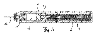
図4、図5及び図6では、自己注射器の3つの状態を示すことにより注射シーケンスを説明している。図4では、安全キャップ8は既に取り外されており、作動装置スリーブ7は遠位方向に動かされている。この時、自己注射器の遠位端は、例えば患者の体の一部(図示せず)上に配置される。作動装置スリーブ7を動かすことにより、保持部5の戻り止め突起6が互いに向けて押され、その結果、ロックが解除される。第1のコイルばね1及び第2のコイルばね2は、弛緩し始める。これにより、ピストン15に圧力がかかり、その結果、遠位方向に動き始める。まず、ピストン15は、圧力ピン4と接触し、同様にこれを動かし始める。ここで、全体として注射ユニット9は、圧力ピン4は、カートリッジ11内で動かないが、圧力ピン4に沿ってカートリッジ11を運び、これを針12に押し当てるように構成される。針は、カートリッジシール16を穿刺し、このようにして、カートリッジ11に接続する。
4, 5 and 6 illustrate the injection sequence by showing three states of the self-injector. In FIG. 4, the safety cap 8 has already been removed and the actuator sleeve 7 has been moved in the distal direction. At this time, the distal end of the auto-injector is placed, for example, on a part of the patient's body (not shown). By moving the actuator sleeve 7, the detent protrusions 6 of the holding
針12及びカートリッジ11が完全に接続されると、圧力ピン4、薬剤入りのカートリッジ11、及び針12は、第1のコイルばね1及び第2のコイルばね2両方がかけるばねの圧力によって、遠位方向にさらに動かされる。針12は、注射ユニット9の遠位端上にあるあらゆるシールをも穿刺し、次いで、針12は、患者の体の一部内に刺し込まれる。次いで、針ホルダ13及びカートリッジ11がそれらの遠位端点となり、注射ユニット9の内部にある止め具に到達するため、ピストン15を介して第1のコイルばね1及び第2のコイルばね2が圧力ピン4に依然としてかけている圧力によって、薬剤が針12を通して放出される。この最後ステップでは、並列に働く、2つのばねの高い圧縮力が解き放たれる。
When the
図6は、注射ユニット9及び本発明による作動装置ユニットを備える自己注射器の最終位置を示している。第1のコイルばね1及び第2のコイルばね2の両方が、圧力ピン4をカートリッジ11の遠位端に動かしている。ここで、薬剤は完全に放出される。
FIG. 6 shows the final position of the self-injector comprising the injection unit 9 and the actuator unit according to the invention. Both the first coil spring 1 and the
図示の本発明による作動装置ユニットを備える自己注射器の実施形態では、2つのばねは同時に働く。従来技術で知られる伸縮自在のスリーブを使用して、第1のコイルばね1及び第2のコイルばね2の一連の動きのシーケンスを達成することも同様に可能である。そのような実施形態では、第1のコイルばね1と第2のコイルばね2とが、カートリッジ11及び針12を遠位方向に押す。このプロセスの間、第2のコイルばね2は、部品にロックされ、そこに保持される。この部品が、それぞれの伸縮自在のスリーブであり得る。第2のコイルばね2は、カートリッジ11と針12とがそれらの最大遠位点に一緒に到達する直前またはちょうどその時に解除される。その瞬間に、第2のコイルばね2は、薬剤を放出するために力をかける。この実施形態の利点は、同様に、薬剤を放出するための力をより大きくして利用できることである。逆に、第2のコイルばね2を最初に解放し、かつロック状態にある第1のコイルばね1を遠位端に動かし、第1のコイルばね1を、カートリッジ11及び針12が自己注射器の遠位端に到達した時のみ、または到達までわずかな距離である時のみ解放することも可能である。
In the embodiment of the self-injector comprising the actuator unit according to the invention shown, the two springs work simultaneously. It is likewise possible to achieve a sequence of movements of the first coil spring 1 and the
時間差解除は、特に粘性の高い有効成分の場合に必要であり、これは、ばね力を大きくすることは、カートリッジ11が針12に接続されるだけでよく、針12が患者の体の一部を刺す自己注射器の動作シーケンスの最初ではそれほど必要とされないが、後は圧力ピン4をカートリッジ11を通して押すだけとなった動作シーケンスの最後では必要となることを意味する。
The time difference cancellation is necessary particularly in the case of active ingredients with high viscosity, and increasing the spring force requires only that the
別の利点は、作動装置が解放された時に生じ、装置を使用する患者が不快と感じる反動力が、本発明による作動装置では従来技術の作動装置よりもかなり低いことである。 Another advantage is that the reaction force, which occurs when the actuator is released and feels uncomfortable for the patient using the device, is considerably lower with the actuator according to the invention than with prior art actuators.
言及した実施形態の様々な修正が考えられる。例えば、第1のコイルばね1を第2のコイルばね2に接続して、一体の二重ばねを形成することができる。これは、コイルばね自体の製造プロセスにおいて、また作動装置ユニットの組立ての際に有利となり得る。ピストン15に対する2つのコイルばねの動作から結果として得られる増加した力の利点は、この実施形態において維持される。作動装置ユニット及び注射ユニット9を、別個及び/または螺合接続により互いに接続可能なものとしてではなく、なんらかの他の手段で互いに接続可能なものまたは最初から単一の部品として製造されるものとして構成することもまた考えられる。
Various modifications of the mentioned embodiments are conceivable. For example, the first coil spring 1 can be connected to the
Claims (10)
軸方向に移動可能な圧力ピン(4)が案内されている実質的に円筒形のハウジング(3)であって、前記圧力ピンがばねユニットに逆行して挿入可能とされ、かつ挿入時に、前記圧力ピンに接続される保持部(5)の戻り止め突起(6)によってロック可能とされる、ハウジング(3)を備え、
前記ばねユニットが、第1のコイルばね(1)と、前記第1のコイルばね(1)よりも大きい直径を有する少なくとも1つの第2のコイルばね(2)とを備え、前記第2のコイルばね(2)が、前記第1のコイルばね(1)に対して同軸であることを特徴とする、作動装置ユニット。 An actuator unit for a self-injector,
A substantially cylindrical housing (3) in which an axially movable pressure pin (4) is guided, said pressure pin being insertable against the spring unit, and when inserted, A housing (3), which can be locked by a detent protrusion (6) of the holding part (5) connected to the pressure pin;
The spring unit comprises a first coil spring (1) and at least one second coil spring (2) having a larger diameter than the first coil spring (1), the second coil Actuator unit, characterized in that the spring (2) is coaxial with the first coil spring (1).
Applications Claiming Priority (3)
| Application Number | Priority Date | Filing Date | Title |
|---|---|---|---|
| ATA514/2013A AT514484B1 (en) | 2013-06-24 | 2013-06-24 | Activator for an auto-injector |
| ATA514/2013 | 2013-06-24 | ||
| PCT/AT2014/000117 WO2014205463A1 (en) | 2013-06-24 | 2014-06-05 | Activator for an autoinjector |
Publications (2)
| Publication Number | Publication Date |
|---|---|
| JP2016524930A true JP2016524930A (en) | 2016-08-22 |
| JP6525972B2 JP6525972B2 (en) | 2019-06-05 |
Family
ID=51059209
Family Applications (1)
| Application Number | Title | Priority Date | Filing Date |
|---|---|---|---|
| JP2016520183A Expired - Fee Related JP6525972B2 (en) | 2013-06-24 | 2014-06-05 | Actuator for self-injector |
Country Status (17)
| Country | Link |
|---|---|
| US (2) | US10105499B2 (en) |
| EP (1) | EP3013392B1 (en) |
| JP (1) | JP6525972B2 (en) |
| KR (3) | KR102414247B1 (en) |
| CN (1) | CN105324141B (en) |
| AT (1) | AT514484B1 (en) |
| AU (1) | AU2014302002B2 (en) |
| BR (1) | BR112015032296B1 (en) |
| CA (1) | CA2916317C (en) |
| HK (1) | HK1224235A1 (en) |
| IL (1) | IL243241B (en) |
| NZ (1) | NZ715705A (en) |
| PL (1) | PL3013392T3 (en) |
| RU (1) | RU2678410C2 (en) |
| SA (1) | SA515370306B1 (en) |
| WO (1) | WO2014205463A1 (en) |
| ZA (1) | ZA201600441B (en) |
Cited By (1)
| Publication number | Priority date | Publication date | Assignee | Title |
|---|---|---|---|---|
| US11364345B2 (en) | 2016-07-19 | 2022-06-21 | Sanofi | Medicament injector device |
Families Citing this family (23)
| Publication number | Priority date | Publication date | Assignee | Title |
|---|---|---|---|---|
| US9173999B2 (en) | 2011-01-26 | 2015-11-03 | Kaleo, Inc. | Devices and methods for delivering medicaments from a multi-chamber container |
| JP6560187B2 (en) | 2013-03-15 | 2019-08-14 | ウインドギャップ メディカル インコーポレイテッド | Portable drug mixing and delivery system and method |
| US10569017B2 (en) | 2013-03-15 | 2020-02-25 | Windgap Medical, Inc. | Portable drug mixing and delivery device and associated methods |
| US9907910B2 (en) | 2013-03-15 | 2018-03-06 | Windgap Medical, Inc. | Portable drug mixing and delivery device and associated methods |
| US20150367073A1 (en) | 2013-03-15 | 2015-12-24 | Windgap Medical, Llc | Portable Drug Mixing and Delivery Device and Associated Methods |
| EP3082419A4 (en) | 2013-12-18 | 2017-09-20 | Windgap Medical, Inc. | Drug mixing and delivery system and method |
| US11116903B2 (en) | 2014-08-18 | 2021-09-14 | Windgap Medical, Inc | Compression seal for use with a liquid component storage vial of an auto-injector |
| CA2971440C (en) | 2014-12-18 | 2024-02-13 | Windgap Medical, Inc. | Method and compositions for dissolving or solubilizing therapeutic agents |
| EP3274021B1 (en) | 2015-03-24 | 2024-02-14 | Kaleo, Inc. | Devices and methods for delivering a lyophilized medicament |
| AU2016287571C1 (en) | 2015-06-30 | 2021-12-23 | Kaleo, Inc. | Auto-injectors for administration of a medicament within a prefilled syringe |
| FR3039069B1 (en) * | 2015-07-24 | 2021-07-23 | Nemera La Verpilliere | AUTOMATIC LIQUID PRODUCT INJECTION DEVICE INCLUDING AN INJECTION SPRING. |
| US10220147B2 (en) | 2015-08-13 | 2019-03-05 | Windgap Medical, Inc. | Mixing and injection device with sterility features |
| CA3009688C (en) | 2016-01-12 | 2024-02-06 | Pharma Consult Ges.M.B.H. | Injection device |
| CN105688314A (en) * | 2016-03-29 | 2016-06-22 | 中国人民解放军军事医学科学院实验仪器厂 | Automatic injection device |
| WO2018119218A1 (en) | 2016-12-23 | 2018-06-28 | Kaleo, Inc. | Medicament delivery device and methods for delivering drugs to infants and children |
| AU2019208338B2 (en) | 2018-01-19 | 2024-11-07 | Birya Biotech, Inc. | Tool for servicing an auto-injector |
| JP7464535B2 (en) | 2018-05-24 | 2024-04-09 | ノバルティス アーゲー | Automated Drug Delivery Device |
| EP3902584A4 (en) | 2018-12-29 | 2022-09-07 | Kaleo, Inc. | DEVICES AND METHODS FOR DELIVERING SUBSTANCES IN A PRE-FILLED SYRINGE |
| US11167087B2 (en) | 2019-08-09 | 2021-11-09 | Kaleo, Inc. | Devices and methods for delivery of substances within a prefilled syringe |
| US12440373B2 (en) * | 2020-06-11 | 2025-10-14 | AesculaTech, Inc. | Device for controlled injection across a variety of material properties |
| US12268847B1 (en) | 2021-02-10 | 2025-04-08 | Kaleo, Inc. | Devices and methods for delivery of substances within a medicament container |
| GB202215446D0 (en) * | 2022-10-19 | 2022-11-30 | Oval Medical Tech Limited | Drug delivery device and method of mixing |
| KR102694739B1 (en) * | 2023-04-05 | 2024-08-14 | 주식회사 비에스엘 | Auto-injector |
Citations (5)
| Publication number | Priority date | Publication date | Assignee | Title |
|---|---|---|---|---|
| FR1538565A (en) * | 1967-07-26 | 1968-09-06 | Automatic hypodermic syringe | |
| JPH07503162A (en) * | 1992-01-24 | 1995-04-06 | アイ−フロー コーポレイション | platen pump |
| US5599309A (en) * | 1993-03-24 | 1997-02-04 | Owen Mumford Limited | Injection devices |
| WO2012049484A2 (en) * | 2010-10-14 | 2012-04-19 | Owen Mumford Limited | Injection devices |
| WO2012073035A1 (en) * | 2010-12-02 | 2012-06-07 | Oval Medical Technologies Limited | Delivery mechanism for an autoinjector |
Family Cites Families (14)
| Publication number | Priority date | Publication date | Assignee | Title |
|---|---|---|---|---|
| US4031893A (en) * | 1976-05-14 | 1977-06-28 | Survival Technology, Inc. | Hypodermic injection device having means for varying the medicament capacity thereof |
| FR2733155B1 (en) * | 1995-04-18 | 1997-09-19 | Tebro | RECHARGEABLE SELF-INJECTOR |
| PT1198263E (en) * | 1999-07-27 | 2003-09-30 | Pharma Consult Gmbh | DEVICE FOR THE AUTOMATIC INJECTION OF INJECTABLE LIQUIDS |
| AT7347U1 (en) | 2003-08-29 | 2005-02-25 | Pharma Consult Ges M B H & Co | DEVICE FOR THE AUTOMATIC INJECTION OF INJECTION LIQUIDS |
| CH696421A5 (en) * | 2003-12-18 | 2007-06-15 | Tecpharma Licensing Ag | Autoinjector with arresting the drug container. |
| BRPI0717260A2 (en) * | 2006-09-29 | 2013-10-15 | Novo Nordisk As | INJECTION DEVICES WITH ELECTRONIC DETECTION |
| EP2162170B1 (en) * | 2007-07-06 | 2011-03-16 | SHL Group AB | One shot injector with dual springs |
| GB2452030A (en) * | 2007-08-10 | 2009-02-25 | Owen Mumford Ltd | Injection devices |
| EP2237817B1 (en) * | 2007-11-14 | 2019-02-13 | SHL Group AB | Automatic injection device with actively triggered syringe withdrawal |
| WO2009147026A1 (en) | 2008-06-02 | 2009-12-10 | Shl Group Ab | Medicament delivery device |
| AT506690B1 (en) * | 2008-06-16 | 2009-11-15 | Pharma Consult Ges M B H & Co | INJECTION DEVICE |
| EP2451511B1 (en) * | 2009-07-08 | 2019-01-23 | Novo Nordisk A/S | Auto-priming injection device |
| KR101746881B1 (en) * | 2009-10-21 | 2017-06-14 | 오웬 멈포드 리미티드 | Autoinjector |
| EP2489380A1 (en) * | 2011-02-18 | 2012-08-22 | Sanofi-Aventis Deutschland GmbH | Injection device |
-
2013
- 2013-06-24 AT ATA514/2013A patent/AT514484B1/en not_active IP Right Cessation
-
2014
- 2014-06-05 EP EP14734374.3A patent/EP3013392B1/en active Active
- 2014-06-05 JP JP2016520183A patent/JP6525972B2/en not_active Expired - Fee Related
- 2014-06-05 KR KR1020217013119A patent/KR102414247B1/en not_active Expired - Fee Related
- 2014-06-05 KR KR1020227021468A patent/KR102512175B1/en active Active
- 2014-06-05 RU RU2015152859A patent/RU2678410C2/en active
- 2014-06-05 KR KR1020167002044A patent/KR20160025569A/en not_active Ceased
- 2014-06-05 PL PL14734374T patent/PL3013392T3/en unknown
- 2014-06-05 US US14/900,923 patent/US10105499B2/en active Active
- 2014-06-05 AU AU2014302002A patent/AU2014302002B2/en not_active Ceased
- 2014-06-05 CA CA2916317A patent/CA2916317C/en active Active
- 2014-06-05 NZ NZ71570514A patent/NZ715705A/en not_active IP Right Cessation
- 2014-06-05 HK HK16112423.4A patent/HK1224235A1/en unknown
- 2014-06-05 WO PCT/AT2014/000117 patent/WO2014205463A1/en not_active Ceased
- 2014-06-05 BR BR112015032296-4A patent/BR112015032296B1/en not_active IP Right Cessation
- 2014-06-05 CN CN201480035765.7A patent/CN105324141B/en not_active Expired - Fee Related
-
2015
- 2015-12-20 IL IL243241A patent/IL243241B/en unknown
- 2015-12-23 SA SA515370306A patent/SA515370306B1/en unknown
-
2016
- 2016-01-20 ZA ZA2016/00441A patent/ZA201600441B/en unknown
-
2018
- 2018-10-10 US US16/156,389 patent/US10780233B2/en active Active
Patent Citations (5)
| Publication number | Priority date | Publication date | Assignee | Title |
|---|---|---|---|---|
| FR1538565A (en) * | 1967-07-26 | 1968-09-06 | Automatic hypodermic syringe | |
| JPH07503162A (en) * | 1992-01-24 | 1995-04-06 | アイ−フロー コーポレイション | platen pump |
| US5599309A (en) * | 1993-03-24 | 1997-02-04 | Owen Mumford Limited | Injection devices |
| WO2012049484A2 (en) * | 2010-10-14 | 2012-04-19 | Owen Mumford Limited | Injection devices |
| WO2012073035A1 (en) * | 2010-12-02 | 2012-06-07 | Oval Medical Technologies Limited | Delivery mechanism for an autoinjector |
Cited By (1)
| Publication number | Priority date | Publication date | Assignee | Title |
|---|---|---|---|---|
| US11364345B2 (en) | 2016-07-19 | 2022-06-21 | Sanofi | Medicament injector device |
Also Published As
| Publication number | Publication date |
|---|---|
| CA2916317A1 (en) | 2014-12-31 |
| CN105324141A (en) | 2016-02-10 |
| KR20220100066A (en) | 2022-07-14 |
| EP3013392A1 (en) | 2016-05-04 |
| AT514484A1 (en) | 2015-01-15 |
| IL243241A0 (en) | 2016-02-29 |
| PL3013392T3 (en) | 2021-02-08 |
| WO2014205463A1 (en) | 2014-12-31 |
| KR102414247B1 (en) | 2022-06-28 |
| US20160144131A1 (en) | 2016-05-26 |
| JP6525972B2 (en) | 2019-06-05 |
| RU2015152859A (en) | 2017-07-26 |
| SA515370306B1 (en) | 2019-04-24 |
| AU2014302002B2 (en) | 2019-05-16 |
| CA2916317C (en) | 2021-10-19 |
| BR112015032296A2 (en) | 2017-07-25 |
| AU2014302002A1 (en) | 2016-01-28 |
| NZ715705A (en) | 2019-11-29 |
| EP3013392B1 (en) | 2020-06-10 |
| BR112015032296B1 (en) | 2022-04-26 |
| KR20210050600A (en) | 2021-05-07 |
| CN105324141B (en) | 2020-11-06 |
| ZA201600441B (en) | 2021-08-25 |
| US20190038845A1 (en) | 2019-02-07 |
| RU2678410C2 (en) | 2019-01-28 |
| US10105499B2 (en) | 2018-10-23 |
| AT514484B1 (en) | 2015-05-15 |
| KR20160025569A (en) | 2016-03-08 |
| HK1224235A1 (en) | 2017-08-18 |
| KR102512175B1 (en) | 2023-03-20 |
| US10780233B2 (en) | 2020-09-22 |
| IL243241B (en) | 2022-04-01 |
Similar Documents
| Publication | Publication Date | Title |
|---|---|---|
| US10780233B2 (en) | Activator for an autoinjector | |
| CN103167887B (en) | Medical injection device | |
| EP3125975B1 (en) | Autoinjector having needle shield triggering | |
| JP2008522754A (en) | Retrofit type fixed needle syringe and automatic injection apparatus having the same | |
| US11395881B2 (en) | Auto-injector apparatus | |
| WO2009103513A4 (en) | Devices for the administration of drugs and vaccines in the form of injectable needles | |
| JP2024535570A (en) | Self-injection device | |
| JP2011510719A (en) | A system that injects fluid through or into the human skin | |
| CA3130827A1 (en) | Cartridge based auto-injector | |
| JP4790846B2 (en) | Injection device | |
| US20210138154A1 (en) | Medical Injection System | |
| RU2440151C1 (en) | Disposable syringe-cartridge with mobile needle (versions) | |
| US10376656B2 (en) | Side-angle decapping of pre-filled syringe |
Legal Events
| Date | Code | Title | Description |
|---|---|---|---|
| A621 | Written request for application examination |
Free format text: JAPANESE INTERMEDIATE CODE: A621 Effective date: 20170602 |
|
| A977 | Report on retrieval |
Free format text: JAPANESE INTERMEDIATE CODE: A971007 Effective date: 20180423 |
|
| A131 | Notification of reasons for refusal |
Free format text: JAPANESE INTERMEDIATE CODE: A131 Effective date: 20180501 |
|
| A601 | Written request for extension of time |
Free format text: JAPANESE INTERMEDIATE CODE: A601 Effective date: 20180718 |
|
| A601 | Written request for extension of time |
Free format text: JAPANESE INTERMEDIATE CODE: A601 Effective date: 20180926 |
|
| A521 | Request for written amendment filed |
Free format text: JAPANESE INTERMEDIATE CODE: A523 Effective date: 20181026 |
|
| A131 | Notification of reasons for refusal |
Free format text: JAPANESE INTERMEDIATE CODE: A131 Effective date: 20181218 |
|
| A521 | Request for written amendment filed |
Free format text: JAPANESE INTERMEDIATE CODE: A523 Effective date: 20190313 |
|
| TRDD | Decision of grant or rejection written | ||
| A01 | Written decision to grant a patent or to grant a registration (utility model) |
Free format text: JAPANESE INTERMEDIATE CODE: A01 Effective date: 20190402 |
|
| A601 | Written request for extension of time |
Free format text: JAPANESE INTERMEDIATE CODE: A601 Effective date: 20190426 |
|
| A61 | First payment of annual fees (during grant procedure) |
Free format text: JAPANESE INTERMEDIATE CODE: A61 Effective date: 20190507 |
|
| R150 | Certificate of patent or registration of utility model |
Ref document number: 6525972 Country of ref document: JP Free format text: JAPANESE INTERMEDIATE CODE: R150 |
|
| R250 | Receipt of annual fees |
Free format text: JAPANESE INTERMEDIATE CODE: R250 |
|
| R250 | Receipt of annual fees |
Free format text: JAPANESE INTERMEDIATE CODE: R250 |
|
| LAPS | Cancellation because of no payment of annual fees |