JP2016524932A - Stent graft - Google Patents
Stent graft Download PDFInfo
- Publication number
- JP2016524932A JP2016524932A JP2016520455A JP2016520455A JP2016524932A JP 2016524932 A JP2016524932 A JP 2016524932A JP 2016520455 A JP2016520455 A JP 2016520455A JP 2016520455 A JP2016520455 A JP 2016520455A JP 2016524932 A JP2016524932 A JP 2016524932A
- Authority
- JP
- Japan
- Prior art keywords
- stent graft
- flap
- compression element
- longitudinal edge
- stent
- Prior art date
- Legal status (The legal status is an assumption and is not a legal conclusion. Google has not performed a legal analysis and makes no representation as to the accuracy of the status listed.)
- Granted
Links
Images


Classifications
-
- A—HUMAN NECESSITIES
- A61—MEDICAL OR VETERINARY SCIENCE; HYGIENE
- A61F—FILTERS IMPLANTABLE INTO BLOOD VESSELS; PROSTHESES; DEVICES PROVIDING PATENCY TO, OR PREVENTING COLLAPSING OF, TUBULAR STRUCTURES OF THE BODY, e.g. STENTS; ORTHOPAEDIC, NURSING OR CONTRACEPTIVE DEVICES; FOMENTATION; TREATMENT OR PROTECTION OF EYES OR EARS; BANDAGES, DRESSINGS OR ABSORBENT PADS; FIRST-AID KITS
- A61F2/00—Filters implantable into blood vessels; Prostheses, i.e. artificial substitutes or replacements for parts of the body; Appliances for connecting them with the body; Devices providing patency to, or preventing collapsing of, tubular structures of the body, e.g. stents
- A61F2/95—Instruments specially adapted for placement or removal of stents or stent-grafts
- A61F2/962—Instruments specially adapted for placement or removal of stents or stent-grafts having an outer sleeve
- A61F2/97—Instruments specially adapted for placement or removal of stents or stent-grafts having an outer sleeve the outer sleeve being splittable
-
- A—HUMAN NECESSITIES
- A61—MEDICAL OR VETERINARY SCIENCE; HYGIENE
- A61F—FILTERS IMPLANTABLE INTO BLOOD VESSELS; PROSTHESES; DEVICES PROVIDING PATENCY TO, OR PREVENTING COLLAPSING OF, TUBULAR STRUCTURES OF THE BODY, e.g. STENTS; ORTHOPAEDIC, NURSING OR CONTRACEPTIVE DEVICES; FOMENTATION; TREATMENT OR PROTECTION OF EYES OR EARS; BANDAGES, DRESSINGS OR ABSORBENT PADS; FIRST-AID KITS
- A61F2/00—Filters implantable into blood vessels; Prostheses, i.e. artificial substitutes or replacements for parts of the body; Appliances for connecting them with the body; Devices providing patency to, or preventing collapsing of, tubular structures of the body, e.g. stents
- A61F2/02—Prostheses implantable into the body
- A61F2/04—Hollow or tubular parts of organs, e.g. bladders, tracheae, bronchi or bile ducts
- A61F2/06—Blood vessels
- A61F2/07—Stent-grafts
-
- A—HUMAN NECESSITIES
- A61—MEDICAL OR VETERINARY SCIENCE; HYGIENE
- A61F—FILTERS IMPLANTABLE INTO BLOOD VESSELS; PROSTHESES; DEVICES PROVIDING PATENCY TO, OR PREVENTING COLLAPSING OF, TUBULAR STRUCTURES OF THE BODY, e.g. STENTS; ORTHOPAEDIC, NURSING OR CONTRACEPTIVE DEVICES; FOMENTATION; TREATMENT OR PROTECTION OF EYES OR EARS; BANDAGES, DRESSINGS OR ABSORBENT PADS; FIRST-AID KITS
- A61F2/00—Filters implantable into blood vessels; Prostheses, i.e. artificial substitutes or replacements for parts of the body; Appliances for connecting them with the body; Devices providing patency to, or preventing collapsing of, tubular structures of the body, e.g. stents
- A61F2/82—Devices providing patency to, or preventing collapsing of, tubular structures of the body, e.g. stents
- A61F2/844—Devices providing patency to, or preventing collapsing of, tubular structures of the body, e.g. stents folded prior to deployment
-
- A—HUMAN NECESSITIES
- A61—MEDICAL OR VETERINARY SCIENCE; HYGIENE
- A61F—FILTERS IMPLANTABLE INTO BLOOD VESSELS; PROSTHESES; DEVICES PROVIDING PATENCY TO, OR PREVENTING COLLAPSING OF, TUBULAR STRUCTURES OF THE BODY, e.g. STENTS; ORTHOPAEDIC, NURSING OR CONTRACEPTIVE DEVICES; FOMENTATION; TREATMENT OR PROTECTION OF EYES OR EARS; BANDAGES, DRESSINGS OR ABSORBENT PADS; FIRST-AID KITS
- A61F2/00—Filters implantable into blood vessels; Prostheses, i.e. artificial substitutes or replacements for parts of the body; Appliances for connecting them with the body; Devices providing patency to, or preventing collapsing of, tubular structures of the body, e.g. stents
- A61F2/82—Devices providing patency to, or preventing collapsing of, tubular structures of the body, e.g. stents
- A61F2/86—Stents in a form characterised by the wire-like elements; Stents in the form characterised by a net-like or mesh-like structure
- A61F2/89—Stents in a form characterised by the wire-like elements; Stents in the form characterised by a net-like or mesh-like structure the wire-like elements comprising two or more adjacent rings flexibly connected by separate members
-
- A—HUMAN NECESSITIES
- A61—MEDICAL OR VETERINARY SCIENCE; HYGIENE
- A61F—FILTERS IMPLANTABLE INTO BLOOD VESSELS; PROSTHESES; DEVICES PROVIDING PATENCY TO, OR PREVENTING COLLAPSING OF, TUBULAR STRUCTURES OF THE BODY, e.g. STENTS; ORTHOPAEDIC, NURSING OR CONTRACEPTIVE DEVICES; FOMENTATION; TREATMENT OR PROTECTION OF EYES OR EARS; BANDAGES, DRESSINGS OR ABSORBENT PADS; FIRST-AID KITS
- A61F2/00—Filters implantable into blood vessels; Prostheses, i.e. artificial substitutes or replacements for parts of the body; Appliances for connecting them with the body; Devices providing patency to, or preventing collapsing of, tubular structures of the body, e.g. stents
- A61F2/95—Instruments specially adapted for placement or removal of stents or stent-grafts
- A61F2002/9505—Instruments specially adapted for placement or removal of stents or stent-grafts having retaining means other than an outer sleeve, e.g. male-female connector between stent and instrument
- A61F2002/9511—Instruments specially adapted for placement or removal of stents or stent-grafts having retaining means other than an outer sleeve, e.g. male-female connector between stent and instrument the retaining means being filaments or wires
Landscapes
- Health & Medical Sciences (AREA)
- Engineering & Computer Science (AREA)
- Biomedical Technology (AREA)
- Heart & Thoracic Surgery (AREA)
- Public Health (AREA)
- Transplantation (AREA)
- Cardiology (AREA)
- Veterinary Medicine (AREA)
- Oral & Maxillofacial Surgery (AREA)
- Vascular Medicine (AREA)
- Life Sciences & Earth Sciences (AREA)
- Animal Behavior & Ethology (AREA)
- General Health & Medical Sciences (AREA)
- Gastroenterology & Hepatology (AREA)
- Pulmonology (AREA)
- Prostheses (AREA)
- Media Introduction/Drainage Providing Device (AREA)
Abstract
ステントグラフト10は、中空円筒状の本体12とスリーブカテーテルとを備える。本体12は、少なくとも自己拡張型ステント14と補綴材16とを備え、本体12の円周は、圧縮状態において、拡張状態における本体12の円周よりも小さい。スリーブカテーテルは、2つの長手方向縁22、24を有するフラップ状の圧縮要素13として具現され、第1の長手方向縁22が本体12に取り付けられている。第1の長手方向縁22に対して垂直方向のフラップ状の圧縮要素13の長さは、拡張状態における本体12の円周よりも小さい。本体12を圧縮するために、フラップ状の圧縮要素13を本体12周囲に配置することができ、自由縁である第2の長手方向縁22は、本体12及び/又はフラップ状の圧縮要素13に設けられた固定点28に取外し可能に固定可能である。The stent graft 10 includes a hollow cylindrical main body 12 and a sleeve catheter. The main body 12 includes at least a self-expanding stent 14 and a prosthetic material 16, and the circumference of the main body 12 is smaller than the circumference of the main body 12 in the expanded state in the compressed state. The sleeve catheter is embodied as a flap-like compression element 13 having two longitudinal edges 22, 24, with the first longitudinal edge 22 being attached to the body 12. The length of the flap-like compression element 13 perpendicular to the first longitudinal edge 22 is smaller than the circumference of the body 12 in the expanded state. In order to compress the body 12, a flap-like compression element 13 can be arranged around the body 12, the second longitudinal edge 22, which is a free edge, on the body 12 and / or the flap-like compression element 13. It can be removably fixed to a fixed point 28 provided.
Description
本発明は、中空円筒状の本体とスリーブカテーテルとを備えるステントグラフトに関する。ここでは、本体は、少なくとも1つの自己拡張型ステントと補綴材(prosthetic material)とを備え、本体の円周は、圧縮状態において、拡張状態における本体の円周よりも小さい。 The present invention relates to a stent graft comprising a hollow cylindrical body and a sleeve catheter. Here, the body comprises at least one self-expanding stent and a prosthetic material, the circumference of the body being smaller in the compressed state than the circumference of the body in the expanded state.
この種のステントグラフトは、従来技術において十分既知である。ステントグラフトは、患者の中空器官、例えば血管内に挿入され、疾患により生じた狭窄部を開放状態に保ち、それにより血流を維持する医療用インプラントの形態をしている。また、ステントグラフトは、動脈瘤、動脈解離(dissections)、及び他の特定の病変の血管内治療に用いられる。通常、ステントグラフトは、長手方向に延びた中空円筒形状を有し、血液は埋め込まれた状態のステントグラフトの中空空間を通って流れることが可能になっている。 This type of stent graft is well known in the prior art. Stent grafts are in the form of medical implants that are inserted into a patient's hollow organ, such as a blood vessel, to keep the stenosis caused by the disease open and thereby maintain blood flow. Stent grafts are also used for endovascular treatment of aneurysms, arterial dissections, and other specific lesions. Usually, the stent graft has a hollow cylindrical shape extending in the longitudinal direction so that blood can flow through the hollow space of the implanted stent graft.
しかし、そのようなステントグラフトが患者の血管内治療の期間にわたって有効であり続けることを確実にするためには、ステントグラフトは治療される部位において適所に固定される必要がある。このことは、ステントグラフトの被覆面(jacket surface)と血管壁との間の十分に広い接触面積によって可能になる。ここでは、ステントグラフトは、被覆面を血管壁に密着して(snugly)配置する必要がある。 However, to ensure that such stent grafts remain effective over the duration of the patient's endovascular treatment, the stent graft needs to be secured in place at the site to be treated. This is made possible by a sufficiently large contact area between the stent graft jacket surface and the vessel wall. Here, the stent graft needs to be placed snugly with the covering surface in contact with the vessel wall.
したがって、従来技術では、自己拡張型ステントを備え、そのため圧縮可能かつ再び拡張可能であるステントグラフトが既知である。したがって、ステントグラフトは、少なくとも2つの状態、すなわち圧縮状態及び拡張状態をとることができる。埋め込むためには、ステントグラフトをまず径方向に圧縮し、それにより、少なくとも本体が患者の血管内に挿入可能になるまで中空円筒状の本体の直径を低減する。圧縮状態を作り出すためには、スリーブカテーテルとして示されているシースにステントグラフトを挿入する。このために、スリーブカテーテルの円周は、拡張状態におけるステントグラフトの円周よりも小さい。ステントグラフトは圧縮状態において、ステントグラフトを包囲するスリーブカテーテルとともに血管内に挿入され、次いで病的部位に位置決めされる。ステントグラフトの位置はX線マーカーを用いて監視することが可能である。ステントグラフトが所望の位置又は向きに達すると、スリーブカテーテルが引き抜かれ、その結果、ステントグラフトは解放されて拡張が可能になる。ステントの自己拡張性に起因して、ステントグラフトは血管内で広がって開放する。ステントグラフトと血管壁との間の圧力の結果、ステントグラフトは所望の位置において適所に固定されたままになる。こうして血管を開放状態に保ち、血流を維持することができる。 Therefore, in the prior art, stent grafts are known that comprise self-expanding stents and are therefore compressible and expandable again. Thus, the stent graft can assume at least two states: a compressed state and an expanded state. For implantation, the stent-graft is first radially compressed, thereby reducing the diameter of the hollow cylindrical body until at least the body can be inserted into a patient's blood vessel. To create the compressed state, a stent graft is inserted into a sheath, shown as a sleeve catheter. For this reason, the circumference of the sleeve catheter is smaller than the circumference of the stent graft in the expanded state. The stent graft is inserted into the blood vessel in a compressed state with a sleeve catheter surrounding the stent graft and then positioned at the diseased site. The position of the stent graft can be monitored using X-ray markers. When the stent graft reaches the desired position or orientation, the sleeve catheter is withdrawn so that the stent graft is released and allowed to expand. Due to the self-expanding nature of the stent, the stent graft expands and opens within the blood vessel. As a result of the pressure between the stent graft and the vessel wall, the stent graft remains fixed in place at the desired location. Thus, the blood vessel can be kept open and blood flow can be maintained.
従来技術では、例えば、ステントが、ステントの自己拡張性を担うワイヤ構造体として形成されるステントグラフトが既知である。通常、ワイヤ構造体は金属又はプラスチックから作製され、さらに、ワイヤ構造体に固定される補綴材によって包囲される。補綴材は布地材料、例えば、血液不透過性のポリエステル織布から構成することができる。そのような材料の生体適合性により、血管壁と拡張したステントグラフトとの間の接触によって合併症を起こさないことが意図される。 In the prior art, for example, stent grafts are known in which the stent is formed as a wire structure responsible for the self-expandability of the stent. Usually, the wire structure is made of metal or plastic and is further surrounded by a prosthetic material fixed to the wire structure. The prosthesis can be composed of a fabric material, for example a blood-impermeable polyester woven fabric. The biocompatibility of such materials is intended to prevent complications from contact between the vessel wall and the expanded stent graft.
特許文献1は、上述のステントを備えるステントグラフトを開示しており、ここでは、拡張状態のステントは、ステントグラフトを患者の血管内に挿入した後に糸を用いて再び圧縮することが可能である。したがって、これにより、既に血管内に挿入されているステントグラフトの抜去が可能になる。 Patent Document 1 discloses a stent graft including the above-described stent, in which an expanded stent can be compressed again using a thread after the stent graft is inserted into a patient's blood vessel. This therefore enables the removal of a stent graft that has already been inserted into the blood vessel.
特許文献2及び特許文献3は、ステントグラフトを挿入した後に、1つ又は複数の糸を用いてステントグラフトの直径を変化させることができる同様のステントグラフトを開示している。特許文献4は、スリーブカテーテルを段階的に引き戻すことができる更なるステントグラフトを開示している。 U.S. Patent Nos. 5,099,086 and 5,037,086 disclose similar stent grafts in which the diameter of the stent graft can be changed using one or more threads after insertion of the stent graft. U.S. Patent No. 6,053,077 discloses a further stent graft that can be pulled back in stages.
上述の文献の全てにおいて、スリーブカテーテルは、ステントグラフトの本体を押し込むことにより圧縮する別個のスリーブ管として示されている。しかしながら、これには、処置を行う人員が、ステントグラフトの本体を部分ごとに折り畳むと同時に、スリーブカテーテルがステントグラフトの本体を完全に包囲するまでステントグラフトの本体をスリーブカテーテルに挿入する必要があることから、圧縮が困難であるという不都合点がある。さらに、ステントグラフトの中空円筒状の本体を拡張するためにスリーブカテーテルを引き抜くのには、一方ではスリーブカテーテルと血管壁との間、他方ではスリーブカテーテルとステントグラフトの本体との間に摩擦力が伴う。これにより、一方では血管壁を損傷させ、他方では、ステントグラフトを、事前にとっていた最適な位置から移動又は捻回させるおそれがある。後者の場合、ステントグラフトの血管内での厄介な再位置決めが必要となる。 In all of the above documents, the sleeve catheter is shown as a separate sleeve tube that compresses by pushing the body of the stent graft. However, this requires that the person performing the procedure folds the stent-graft body piece by piece and simultaneously inserts the stent-graft body into the sleeve catheter until the sleeve catheter completely surrounds the stent-graft body. There is a disadvantage that compression is difficult. Furthermore, withdrawing the sleeve catheter to expand the hollow cylindrical body of the stent graft involves frictional forces on the one hand between the sleeve catheter and the vessel wall and on the other hand between the sleeve catheter and the stent graft body. This can damage the vessel wall on the one hand and move or twist the stent graft from the optimal position it had previously. In the latter case, a troublesome repositioning of the stent graft within the blood vessel is required.
こうした背景に対し、本発明の目的は、冒頭に述べたタイプのステントグラフトを、本体を簡単に圧縮することができ、同様に、より低い摩擦で血管内において容易に解放及び拡張することができるように発展させることである。 Against this background, the object of the present invention is to make it possible for a stent graft of the type mentioned at the outset to easily compress the body, as well as to be easily released and expanded in blood vessels with lower friction. It is to develop into.
本発明によれば、上述の目的は、スリーブカテーテルが、2つの長手方向縁を有するフラップ状の圧縮要素として設計されることによって達成される。この場合、第1の長手方向縁は本体に固定されており、第1の長手方向縁に対して垂直方向のフラップ状の圧縮要素の長さ(extent)は、拡張状態における本体の円周よりも小さく、本体を圧縮する目的で、フラップ状の圧縮要素を本体周囲に配置することができ、自由縁である第2の長手方向縁は、本体及び/又はフラップ状の圧縮要素に設けられた固定点に解放可能に取付け可能である。 According to the invention, the above object is achieved by the sleeve catheter being designed as a flap-like compression element having two longitudinal edges. In this case, the first longitudinal edge is fixed to the body, and the length of the flap-like compression element perpendicular to the first longitudinal edge is greater than the circumference of the body in the expanded state. For the purpose of compressing the body, a flap-like compression element can be arranged around the body, the second longitudinal edge being a free edge provided on the body and / or the flap-like compression element Can be releasably attached to a fixed point.
本発明によれば、スリーブカテーテルは、フラップ状の圧縮要素として設計されるとともに2つの長手方向縁を有する。この場合、第1の長手方向縁は本体に固定されている。したがって、従来技術とは対照的に、スリーブカテーテルはステントグラフトに固定されている。さらに、フラップ状の圧縮要素は、第1の長手方向縁に対して垂直方向に、拡張状態におけるステントグラフトの本体の円周よりも小さい長さを有する。これにより、ステントグラフトの本体は、血管内への挿入前にフラップ状の圧縮要素によって圧縮することができる。フラップ状の圧縮要素の長手方向自由縁を固定する固定点は、ステントグラフトの本体及び/又はフラップ状の圧縮要素に設けられる。 According to the invention, the sleeve catheter is designed as a flap-like compression element and has two longitudinal edges. In this case, the first longitudinal edge is fixed to the body. Thus, in contrast to the prior art, the sleeve catheter is secured to the stent graft. Further, the flap-like compression element has a length perpendicular to the first longitudinal edge that is less than the circumference of the stent-graft body in the expanded state. This allows the main body of the stent graft to be compressed by a flap-like compression element prior to insertion into the blood vessel. A fixation point for fixing the longitudinal free edge of the flap-like compression element is provided on the stent-graft body and / or the flap-like compression element.
ステントグラフトの本体を圧縮するためには、フラップ状の圧縮要素が本体を部分的又は完全に包囲するように、フラップ状の圧縮要素を本体周囲に配置する。したがって、ステントは径方向内方に圧縮され、ステントグラフトの本体の断面サイズが減少する。次いで、第2の長手方向縁は、本体及び/又はフラップ状の圧縮要素に設けられた固定点に解放可能に取り付けられる。このように、本体を包み込むことによって本体の圧縮が可能であり、それにより、ステントグラフトをスリーブ管に挿入するよりも取扱いが簡単になることが有利である。更なる利点は、フラップ状の圧縮要素により、圧縮された後のステントグラフトは滑らかな表面を有し、それによりステントグラフトを血管内に挿入することが容易になることである。 To compress the stent-graft body, the flap-like compression elements are placed around the body such that the flap-like compression elements partially or completely surround the body. Thus, the stent is compressed radially inward, reducing the cross-sectional size of the stent graft body. The second longitudinal edge is then releasably attached to a fixation point provided on the body and / or the flap-like compression element. In this way, the body can be compressed by wrapping the body, which is advantageously easier to handle than inserting the stent graft into the sleeve tube. A further advantage is that the flap-like compression element allows the stent graft after compression to have a smooth surface, thereby facilitating insertion of the stent graft into the blood vessel.
ステントグラフトを血管内に挿入し、ステントグラフトを所望の部位に位置決めした後、ステントグラフトの本体を拡張するために、第2の長手方向縁を固定点から取り外すことができる。しかし、フラップ状の圧縮要素は血管から引き抜かれず、代わりに血管内のステントグラフトの本体に残る。このことは、圧縮要素が第1の長手方向縁によって本体に固定されていることによって可能であり、そのため、血管内で圧縮要素が移動する危険がない。圧縮要素によって形成されるスリーブカテーテルは血管から引き抜かれないことから、スリーブカテーテルと血管壁との間、またスリーブカテーテルとステントグラフトの本体との間の摩擦力が回避され、その結果、血管壁に対する損傷を回避することと、ステントグラフトが位置を変える場合に必要な再位置決めを回避することとが可能になる。本発明に係るステントグラフトの更なる利点は、手術時間を低減することができることである。 After inserting the stent graft into the blood vessel and positioning the stent graft at the desired site, the second longitudinal edge can be removed from the fixation point to expand the body of the stent graft. However, the flap-like compression element is not withdrawn from the vessel and instead remains in the body of the stent graft within the vessel. This is possible because the compression element is secured to the body by the first longitudinal edge, so that there is no risk of the compression element moving within the blood vessel. Since the sleeve catheter formed by the compression element is not withdrawn from the vessel, frictional forces between the sleeve catheter and the vessel wall and between the sleeve catheter and the stent graft body are avoided, resulting in damage to the vessel wall. And avoiding the repositioning required when the stent graft changes position. A further advantage of the stent graft according to the present invention is that the operation time can be reduced.
好ましい一実施形態において、フラップ状の圧縮要素は、本体の圧縮状態では、第1の長手方向縁に対して垂直方向に、少なくともステントグラフトの本体の回りの全周に延在する。 In a preferred embodiment, the flap-like compression element extends in the compressed state of the body, perpendicular to the first longitudinal edge, at least around the circumference of the stent-graft body.
この手法では、本体を、外径が最小限になるまで圧縮することができることが有利である。それによりまた、本体の圧縮状態がステントグラフトの全周の回りに均一に達成され、血管内へのステントグラフトの挿入と、血管内におけるステントグラフトの位置決めとがより容易になる。 This approach advantageously allows the body to be compressed until the outer diameter is minimized. Thereby, the compression state of the body is also achieved uniformly around the entire circumference of the stent graft, making it easier to insert the stent graft into the vessel and position the stent graft within the vessel.
別の好ましい実施形態において、フラップ状の圧縮要素は本体と略同じ長さである。 In another preferred embodiment, the flap-like compression element is approximately the same length as the body.
この手法では、本体を全長にわたって均一に圧縮することが可能である。これにより、ステントグラフトの血管内への挿入と、血管内におけるステントグラフトの位置決めとが更に容易になる。 In this method, the main body can be uniformly compressed over the entire length. This further facilitates insertion of the stent graft into the blood vessel and positioning of the stent graft within the blood vessel.
別の好ましい実施形態において、フラップ状の圧縮要素の第1の長手方向縁は補綴材に固定されている。 In another preferred embodiment, the first longitudinal edge of the flap-like compression element is fixed to the prosthesis.
この手法は、フラップ状の圧縮要素を、ステントグラフトの本体に特に容易に固定することができるという利点を有する。フラップ状の圧縮要素は、補綴材と同様に布地構造体とすることができ、それにより、フラップ状の圧縮要素は、例えば縫合部によって補綴材に容易に固定することができる。縫合部による固定には、ステントグラフトの表面の滑らかさを損なうことがなく、フラップ状の圧縮要素が本体から分離しないという利点がある。 This approach has the advantage that the flap-like compression element can be fixed particularly easily to the body of the stent-graft. The flap-like compression element can be a fabric structure similar to the prosthetic material, whereby the flap-like compression element can be easily fixed to the prosthetic material, for example, by a suture. The fixation with the suture has the advantages that the smoothness of the surface of the stent-graft is not impaired and the flap-like compression element does not separate from the body.
別の好ましい実施形態において、本体及び/又はフラップ状の圧縮要素に設けられた固定点は、フラップ状の圧縮要素の第2の長手方向縁を固定するためにロッドを突き通すことができるループを有する。 In another preferred embodiment, the fixing point provided on the body and / or the flap-like compression element has a loop through which the rod can be penetrated in order to fix the second longitudinal edge of the flap-like compression element. .
この手法では、本体を拡張する簡単な方法を利用可能であることが有利であり、この方法では、摩擦力はステントグラフトとスリーブカテーテルとの間には生じず、ループとロッドとの間にのみ生じ、この生じる摩擦力は、スリーブカテーテルをステントグラフトから引き離す場合及びスリーブカテーテルを血管から引き抜く場合よりも実質的に小さい。ロッドは、特に滑らかで、したがって低摩擦性の表面を有し、例えばステンレス鋼から作製することができ、そのため引き抜く際に血管壁を損傷しない。したがって、本体の拡張中に生じる摩擦力を大幅に低減することができ、拡張に必要な時間を短縮することができる。さらに、ロッドを引き抜く際、本体はロッドとともに引っ張られない。さらに、ループは本体及び/又はフラップ状の圧縮要素に、例えば結ぶことにより容易に固定することができる。各固定点は1つ又は複数のループを有することができることが理解される。 In this approach, it is advantageous to be able to use a simple method of expanding the body, in which friction does not occur between the stent graft and the sleeve catheter, but only between the loop and the rod. This resulting frictional force is substantially less than when the sleeve catheter is pulled away from the stent graft and when the sleeve catheter is pulled out of the blood vessel. The rod has a particularly smooth and therefore low friction surface and can be made, for example, from stainless steel so that it does not damage the vessel wall when it is withdrawn. Therefore, the frictional force generated during expansion of the main body can be greatly reduced, and the time required for expansion can be shortened. Furthermore, when pulling out the rod, the body is not pulled with the rod. Furthermore, the loop can be easily fixed to the body and / or the flap-like compression element, for example by tying. It will be appreciated that each fixed point may have one or more loops.
別の好ましい実施形態において、フラップ状の圧縮要素の第2の長手方向縁は、ロッドを挿入可能なヘムステッチ(hemstitch:縁縫い)を有する。 In another preferred embodiment, the second longitudinal edge of the flap-like compression element has a hemstitch into which the rod can be inserted.
この手法は、自由縁である第2の長手方向縁全体を、好ましくは第1の長手方向縁の長さを超える長さのロッドの挿入により、本体に均一に固定することができることから有利である。したがって、ステントグラフトの本体に生じる圧縮状態の均一性は、ロッドをヘムステッチに挿入し、ロッドをループに突き通した後、更に向上する。圧縮要素の第1の長手方向縁の領域上又はこの領域内にループが設けられる場合、この手法の更なる利点は、フラップ状の圧縮要素の2つの長手方向縁を互いに直接接続することができることである。それにより、フラップ状の圧縮要素の略全面を用いて、直径が最小限になるまで本体が圧縮される。 This approach is advantageous because the entire second longitudinal edge, which is a free edge, can be uniformly fixed to the body, preferably by insertion of a rod with a length that exceeds the length of the first longitudinal edge. is there. Thus, the compressive uniformity that occurs in the body of the stent graft is further improved after the rod is inserted into the hemstitch and pierced through the loop. If a loop is provided on or in the region of the first longitudinal edge of the compression element, a further advantage of this approach is that the two longitudinal edges of the flap-like compression element can be directly connected to each other. It is. Thereby, the main body is compressed using the substantially entire surface of the flap-like compression element until the diameter is minimized.
別の好ましい実施形態において、ヘムステッチは複数の切れ目(interruptions)を有し、この場合、ループは、本体の長手方向において、ループが切れ目の高さのところに位置するように設けられる。 In another preferred embodiment, the hem stitch has a plurality of interruptions, in which case the loop is provided so that the loop is located at the height of the cut in the longitudinal direction of the body.
この実施形態では、ヘムステッチは個々のヘムステッチ部を有し、個々のヘムステッチ部の間には、ロッドがヘムステッチ部及びループに突き通されるごとに1つ又は複数のループが配置される。この手法の利点は、ロッドがループ及びヘムステッチ部から引き抜かれる場合、ステントグラフトの本体がジッパーのように長手方向に連続して解放され拡張されることである。このようにして、ステントグラフトの血管内での位置決めは、ステントグラフトを徐々に解放する間でも段階的に最適化することができる。さらに、ロッドはヘムステッチの切れ目の領域において視認可能であり、その結果、拡張手順の誤りが容易に検出される。すなわち、ステントグラフトの本体の一部が、本体のこの部分に配置されたループからロッドが引き抜かれているにもかかわらず拡張しない場合、それにより即座に対抗手段をとることができる。 In this embodiment, the hem stitch has individual hem stitch portions, and one or more loops are arranged between the individual hem stitch portions each time the rod is pierced by the hem stitch portion and the loop. The The advantage of this approach is that when the rod is withdrawn from the loop and hemstitch, the body of the stent graft is released and expanded continuously in the longitudinal direction like a zipper. In this way, the positioning of the stent graft in the blood vessel can be optimized in stages even during the gradual release of the stent graft. Furthermore, the rod is visible in the area of the hem stitch break, so that errors in the expansion procedure are easily detected. That is, if a portion of the stent-graft body does not expand despite the rod being pulled out of the loop located in this portion of the body, it can immediately take counter measures.
別の好ましい実施形態において、切れ目は互いに均一な距離を置いている。 In another preferred embodiment, the cuts are at a uniform distance from each other.
この手法により、フラップ状の圧縮要素の第2の長手方向縁の均一な固定が可能になる。 This approach allows for a uniform fixation of the second longitudinal edge of the flap-like compression element.
別の好ましい実施形態において、フラップ状の圧縮要素は吸収性材料から作製される。 In another preferred embodiment, the flap-like compression element is made from an absorbent material.
この手法の利点は、ステントグラフトを挿入して拡張した後、圧縮要素がその機能を果たした後に分解することが可能であることである。圧縮要素の材料は生体適合性であることが理解される。圧縮要素は織布から作製することもでき、この織布は吸収性であっても吸収性でなくてもよい。 The advantage of this approach is that after the stent graft is inserted and expanded, it can be disassembled after the compression element performs its function. It will be appreciated that the material of the compression element is biocompatible. The compression element can also be made from a woven fabric, which may or may not be absorbent.
別の好ましい実施形態において、フラップ状の圧縮要素は径方向折畳み構造を有する。 In another preferred embodiment, the flap-like compression element has a radially folded structure.
本体の拡張状態において、拡張をもたらすステントグラフトの伸長力は、フラップ状の圧縮要素にわたる表面に実質的に作用し、血管内のステントグラフトは、径方向折畳み構造によってよりしっかりと適所に固定される。この手法により、拡張状態における本発明に係るステントグラフトの位置安定性が向上することが有利である。 In the expanded state of the body, the expansion force of the stent graft that causes expansion substantially acts on the surface across the flap-like compression element, and the stent graft within the vessel is more firmly secured in place by the radially folded structure. This approach advantageously improves the positional stability of the stent graft according to the invention in the expanded state.
別の好ましい実施形態において、フラップ状の圧縮要素は、低摩擦性の、好ましくは変形可能な(formable)、より好ましくは非侵襲性の表面を有する。 In another preferred embodiment, the flap-like compression element has a low friction, preferably formable, more preferably a non-invasive surface.
この手法の利点は、圧縮要素を血管壁に対する最小限の摩擦で挿入することができ、患者の血管壁を損傷しないことである。さらに、スリーブカテーテルは、変形可能であることにより、血管の内側形状又は経路に容易に適合することができ、血管壁に密着して支持される。 The advantage of this approach is that the compression element can be inserted with minimal friction against the vessel wall and does not damage the patient's vessel wall. In addition, the sleeve catheter is deformable so that it can easily conform to the inner shape or path of the blood vessel and is supported in close contact with the vessel wall.
別の好ましい実施形態において、フラップ状の圧縮要素は布地材料から作製される。 In another preferred embodiment, the flap-like compression element is made from a fabric material.
この手法の利点は、圧縮要素(フラップ)が、スリーブカテーテルと比較して大幅に柔軟であることである。したがって、かなり迂曲した血管の解剖学的構造(anatomies)においても、ステントグラフトシステムを展開位置に進めることが可能である。ここでは、「布地材料」とは、任意のシート状の布地構造体、特に繊維から構成される布地構造体、例えば、組紐、織物、メッシュ、及びニットとして理解される。繊維は、紡績可能であり、上述したように、組む、織る、メッシュ編みする、又はニット編みすることができる無端繊維である。 The advantage of this approach is that the compression element (flap) is significantly more flexible than the sleeve catheter. Thus, it is possible to advance the stent-graft system to the deployed position even in highly diverted blood vessel anatomies. Here, “fabric material” is understood as any sheet-like fabric structure, in particular a fabric structure composed of fibers, such as braids, fabrics, meshes and knits. The fibers are endless fibers that can be spun and that can be knitted, woven, mesh knitted, or knitted as described above.
更なる利点及び特徴は、以下の記載及び添付図面から明らかとなる。 Further advantages and features will become apparent from the following description and the accompanying drawings.
上述の特徴及び下記にこれから説明する特徴は、それぞれ述べられている組合せだけでなく、本発明の範囲から逸脱することなく、他の組合せ又は単独でも用いることができることが理解される。 It will be understood that the features described above and those which will be described below can be used not only in the respective combinations mentioned, but also in other combinations or alone, without departing from the scope of the invention.
本発明の例示的な一実施形態を図面において示し、図面を参照して下記により詳細に記載する。 An exemplary embodiment of the present invention is shown in the drawings and is described in more detail below with reference to the drawings.
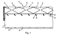
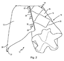
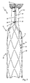
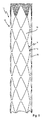
図1及び図2は、全体として参照符号10で示されているステントグラフトの例示的な一実施形態を示している。このステントグラフトは、中空円筒状の本体12と、フラップ状の圧縮要素13として示されているスリーブカテーテルとを備える。本体12は、自己拡張型ステント14と補綴材16とを備える。ステント14は、中空円筒状の本体12の長手方向に連続して配置され、蛇行する支持材20から構成されるリングセグメント18を備える。補綴材、例えば布地構造体は、縫合部15によってリングセグメント18に固定されている。これらの縫合部は後続の図のいずれにも示していない。
FIGS. 1 and 2 illustrate an exemplary embodiment of a stent graft, indicated generally by the
図2の斜視図から見て取ることができるように、本体12は中空円筒体である。フラップ状の圧縮要素13は、本体12に固定された第1の長手方向縁22と、自由縁である第2の長手方向縁24とを有し、第1の長手方向縁22は縫合部26によって補綴材16に固定されている。フラップ状の圧縮要素13は、双方の長手方向縁22、24に対して垂直方向に、圧縮状態における本体12の円周に実質的に相当する長さを有する。フラップ状の圧縮要素13は、長手方向において、すなわち長手方向縁に対して平行に、本体12と略同じ長さを有する。
As can be seen from the perspective view of FIG. 2, the
本体12及び/又はフラップ状の圧縮要素13において、この例ではフラップ状の圧縮要素13において、フラップ状の圧縮要素13の第1の長手方向縁22の領域に固定されたループ30を有する固定点28が設けられる。さらに、第2の長手方向縁24には、切れ目34を有するヘムステッチ32が形成される。ヘムステッチ32の切れ目34は、本体12の長手方向において、ヘムステッチ32の切れ目34がループ30の高さのところに位置するように設けられる。さらに、切れ目34は互いに均一な距離だけ離間している。
In the
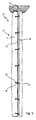
ステントグラフト10を患者(図示せず)の血管(図示せず)内に挿入する前に、ステントグラフト10はまず最初に圧縮される。圧縮の開始状態が図1及び図2に示されている。圧縮の際、フラップ状の圧縮要素13は、フラップ状の圧縮要素13の双方の長手方向縁22、24が互いに実質的に重なるように本体12周囲に配置される。こうして、本体12は、拡張状態における本体12の円周よりも小さい円周まで径方向に圧縮される。これは図3及び図4に見て取ることができる。
Prior to inserting the
ステントグラフトを血管内に挿入する前及び挿入する間、ステントグラフト10の圧縮状態を維持するために、ロッド36を、圧縮要素13の長手方向端部にあるヘムステッチ32に挿入し、ヘムステッチ32を通して導く。このプロセスにおいて、ここでは切れ目34の領域に配置されているループ30に、ロッド36が同様に突き通される。図3に示されているように、ループ30の全てにロッド36が突き通される場合、長手方向縁24は固定され、また本体12は圧縮状態を保持する。
Before and during insertion of the stent graft into the blood vessel, the
この均一な圧縮状態では、ステントグラフト10を患者の血管内に挿入することができ、血管における治療される部位に位置決めすることができる。次に、ロッド36をヘムステッチ32及びループ30から引き戻すことによって本体12を解放し、拡張状態にする。次に、本体12の拡張が、ステント14の自己拡張性に起因して自動的に起こる。
In this uniform compression state, the
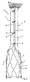
図5〜図8において、本発明に係るステントグラフト10が、連続する解放及び拡張中の複数の異なる段階において示されている。ステントグラフト10を拡張するために、ロッド36は、ヘムステッチ32及びループ30から長手方向に徐々に引き抜かれる。ループ30のうちの最初のループがロッド36から取り外されるとすぐに、フラップ状の圧縮要素13の長手方向縁24が、この時点において、ループ30のうちのこの最初のループとループ30のうちの次のループとの間に位置する、本体12の第1の部分38に沿って緩む。ステント14の自己拡張性に起因して、本体12の第1の部分38は拡張状態に広がる。本体の更なる部分40は、初めは均一に圧縮されたままである。ロッド36を更に引き抜くことにより、本体12の残りの部分は徐々に解放され、拡張する。
5-8, a
さらに、本体12の拡張中、ステントグラフト10の位置を最適化することが可能である。詳細には、ステントグラフト10の位置決めは、ロッド32を段階的にヘムステッチ32から引き抜くことによって、段階的に最適化することができる。
Furthermore, the position of the
ステントグラフト10が未だ部分的に圧縮されているが既に部分的に拡張している、図5〜図7に示されているステントグラフト10の状態のうちの1つにおいて、特に図5及び図6に従った状態において、ステントグラフト10の位置は摺動及び/又は回動によって最適化することが可能である。
In one of the states of the
ステントグラフト10の位置決めが適切な場合に最適化され、更なる補正を行わない場合、本発明に係るステントグラフト10を完全に拡張させるために、ロッド36をヘムステッチ32から完全に引き抜くことができる。ステントグラフト10の完全拡張状態は図8に示されている。圧縮要素13(図8には図示せず)は本体12に留まる。すなわち、圧縮要素13の第1の長手方向縁22が本体12に固定されたままである。
If the positioning of the
フラップ状の圧縮要素13は織布から製造することができ、フラップ状の圧縮要素13の形状、成形性、及び表面性質を、血管の形状及び経路によって課される要件に最適に適合させることが可能である。特に、フラップ状の圧縮要素13は、本発明に係るステントグラフト10の血管内での位置安定性を更に向上させる径方向折畳み構造を有することができる。吸収性材料を使用することにより、フラップ状の圧縮要素13は、血管内において或る特定の期間の後、生分解されるように製造することができる。それとは別に、本発明に係るステントグラフト10を用いる処置によって合併症を可能な限り起こさないことを保証するように、圧縮要素は生体適合性材料から製造されることが好ましい。
The flap-
Claims (11)
前記本体(12)は、少なくとも1つの自己拡張型ステント(14)と補綴材(16)とを備え、
前記本体(12)の円周は、圧縮状態において、拡張状態における前記本体(12)の円周よりも小さく、
前記スリーブカテーテルは、2つの長手方向縁(22、24)を有するフラップ状の圧縮要素(13)として設計され、
第1の長手方向縁(22)が前記本体(12)に固定され、
前記第1の長手方向縁(22)に対して垂直方向の前記フラップ状の圧縮要素(13)の長さは、前記拡張状態における前記本体(12)の前記円周よりも小さく、
前記本体(12)を圧縮する目的で、前記フラップ状の圧縮要素(13)を前記本体(12)周囲に配置することができ、
自由縁である第2の長手方向縁(22)が、前記本体(12)及び/又は前記フラップ状の圧縮要素(13)に設けられた固定点(28)に解放可能に取付け可能であることを特徴とする、ステントグラフト。 A stent graft (10) comprising a hollow cylindrical body (12) and a sleeve catheter,
The body (12) comprises at least one self-expanding stent (14) and a prosthesis (16),
The circumference of the body (12) is smaller in the compressed state than the circumference of the body (12) in the expanded state,
The sleeve catheter is designed as a flap-like compression element (13) having two longitudinal edges (22, 24);
A first longitudinal edge (22) is secured to the body (12);
The length of the flap-like compression element (13) perpendicular to the first longitudinal edge (22) is smaller than the circumference of the body (12) in the expanded state,
For the purpose of compressing the body (12), the flap-like compression element (13) can be arranged around the body (12),
A second longitudinal edge (22), which is a free edge, can be releasably attached to a fixing point (28) provided on the body (12) and / or the flap-like compression element (13). A stent graft.
Applications Claiming Priority (3)
| Application Number | Priority Date | Filing Date | Title |
|---|---|---|---|
| DE102013106463.9 | 2013-06-20 | ||
| DE102013106463.9A DE102013106463A1 (en) | 2013-06-20 | 2013-06-20 | stent graft |
| PCT/EP2014/062784 WO2014202645A1 (en) | 2013-06-20 | 2014-06-18 | Stent graft |
Publications (2)
| Publication Number | Publication Date |
|---|---|
| JP2016524932A true JP2016524932A (en) | 2016-08-22 |
| JP6472792B2 JP6472792B2 (en) | 2019-02-20 |
Family
ID=50976646
Family Applications (1)
| Application Number | Title | Priority Date | Filing Date |
|---|---|---|---|
| JP2016520455A Active JP6472792B2 (en) | 2013-06-20 | 2014-06-18 | Stent graft |
Country Status (8)
| Country | Link |
|---|---|
| US (1) | US10363155B2 (en) |
| EP (1) | EP3010443B1 (en) |
| JP (1) | JP6472792B2 (en) |
| CN (1) | CN105377187B (en) |
| DE (1) | DE102013106463A1 (en) |
| ES (1) | ES2932768T3 (en) |
| PL (1) | PL3010443T3 (en) |
| WO (1) | WO2014202645A1 (en) |
Families Citing this family (16)
| Publication number | Priority date | Publication date | Assignee | Title |
|---|---|---|---|---|
| US9687371B2 (en) * | 2012-02-14 | 2017-06-27 | W. L. Gore & Associates, Inc. | Endoprosthesis having aligned legs for ease of cannulation |
| US11839698B2 (en) | 2014-03-13 | 2023-12-12 | W. L. Gore & Associates, Inc. | Drug composition and coating |
| JP7112393B2 (en) * | 2017-02-24 | 2022-08-03 | ボルトン メディカル インコーポレイテッド | Stent graft delivery system with retracted sheath and method of use |
| ES2993582T3 (en) | 2017-02-24 | 2025-01-02 | Bolton Medical Inc | System to radially constrict a stent graft |
| JP7042259B2 (en) | 2017-02-24 | 2022-03-25 | ボルトン メディカル インコーポレイテッド | Delivery system for radial contraction of stent graft |
| WO2018156851A1 (en) | 2017-02-24 | 2018-08-30 | Bolton Medical, Inc. | Vascular prosthesis with moveable fenestration |
| WO2018156848A1 (en) | 2017-02-24 | 2018-08-30 | Bolton Medical, Inc. | Vascular prosthesis with crimped adapter and methods of use |
| WO2018156850A1 (en) | 2017-02-24 | 2018-08-30 | Bolton Medical, Inc. | Stent graft with fenestration lock |
| WO2018156854A1 (en) | 2017-02-24 | 2018-08-30 | Bolton Medical, Inc. | Radially adjustable stent graft delivery system |
| DE102017115898A1 (en) * | 2017-07-14 | 2019-01-17 | Jotec Gmbh | Intraluminal vascular prosthesis |
| CN112773583B (en) * | 2017-08-11 | 2024-01-09 | 万能医药公司 | Open the bracket |
| ES2910187T3 (en) | 2017-10-31 | 2022-05-11 | Bolton Medical Inc | Distal torque component, delivery system and method of use thereof |
| KR20210027450A (en) * | 2018-07-03 | 2021-03-10 | 아퀴데온 메디컬, 인코포레이티드 | Vascular and aortic grafts and deployment tools |
| JP7463499B2 (en) | 2019-09-25 | 2024-04-08 | アキューデオン・メディカル・インコーポレイテッド | Vascular and aortic grafts and deployment tools |
| DK4096588T3 (en) | 2020-03-04 | 2024-10-21 | Aquedeon Medical Inc | Instrument for the construction of a vascular and aortic graft connector with telescopic sheath |
| AU2021356662A1 (en) | 2020-10-07 | 2023-06-15 | Canary Medical Switzerland Ag | Providing medical devices with sensing functionality |
Citations (3)
| Publication number | Priority date | Publication date | Assignee | Title |
|---|---|---|---|---|
| US20120130475A1 (en) * | 2010-11-16 | 2012-05-24 | Shaw Edward E | Sleeves for expandable medical devices |
| JP2012512671A (en) * | 2008-12-15 | 2012-06-07 | ボストン サイエンティフィック サイムド,インコーポレイテッド | Unbalanced connection area |
| US20130018450A1 (en) * | 2011-07-13 | 2013-01-17 | Hunt James B | Prosthesis delivery system with retention sleeve |
Family Cites Families (25)
| Publication number | Priority date | Publication date | Assignee | Title |
|---|---|---|---|---|
| US6015429A (en) * | 1994-09-08 | 2000-01-18 | Gore Enterprise Holdings, Inc. | Procedures for introducing stents and stent-grafts |
| US6352561B1 (en) * | 1996-12-23 | 2002-03-05 | W. L. Gore & Associates | Implant deployment apparatus |
| US6899727B2 (en) * | 2001-01-22 | 2005-05-31 | Gore Enterprise Holdings, Inc. | Deployment system for intraluminal devices |
| DE10335948B3 (en) | 2003-08-04 | 2005-02-03 | Qualimed Innovative Medizinprodukte Gmbh | Stent for medical applications comprises a tubular support structure made from joined ring segments and twisted by a thread with ends guided into the support structure via a deviating unit and coupled by a connector |
| DE10346200A1 (en) * | 2003-09-30 | 2005-05-04 | Jotec Gmbh | Delivery system with a self-expanding stent |
| US8308789B2 (en) * | 2004-07-16 | 2012-11-13 | W. L. Gore & Associates, Inc. | Deployment system for intraluminal devices |
| FR2894131B1 (en) | 2005-12-02 | 2008-12-05 | Perouse Soc Par Actions Simpli | DEVICE FOR TREATING A BLOOD VESSEL, AND ASSOCIATED TREATMENT NECESSARY. |
| US9375215B2 (en) * | 2006-01-20 | 2016-06-28 | W. L. Gore & Associates, Inc. | Device for rapid repair of body conduits |
| DE102007010305A1 (en) * | 2007-02-22 | 2008-08-28 | Jotec Gmbh | Device for releasing a self-expanding stent into a body vessel |
| US8226701B2 (en) * | 2007-09-26 | 2012-07-24 | Trivascular, Inc. | Stent and delivery system for deployment thereof |
| GB0822110D0 (en) * | 2008-12-03 | 2009-01-07 | Angiomed Ag | Catheter sheath for implant delivery |
| US20100274276A1 (en) * | 2009-04-22 | 2010-10-28 | Ricky Chow | Aneurysm treatment system, device and method |
| JP5744028B2 (en) * | 2009-08-27 | 2015-07-01 | メドトロニック,インコーポレイテッド | Transcatheter valve delivery system and method |
| JP5685256B2 (en) * | 2009-09-21 | 2015-03-18 | メドトロニック,インコーポレイテッド | Stented transcatheter prosthetic heart valve delivery system and method |
| DE102009055969A1 (en) | 2009-11-27 | 2011-06-01 | Transcatheter Technologies Gmbh | Device and set for folding or unfolding a medical implant and method |
| US9326872B2 (en) * | 2010-08-17 | 2016-05-03 | W. L. Gore & Associates, Inc. | Forced deployment sequence handle assembly with independent actuating mechanism |
| US9468547B2 (en) * | 2010-11-11 | 2016-10-18 | W. L. Gore & Associates, Inc. | Deployment of endoluminal devices |
| US9095466B2 (en) * | 2010-11-16 | 2015-08-04 | W. L. Gore & Associates, Inc. | Apposition fiber for use in endoluminal deployment of expandable devices in tortuous anatomies |
| US10117765B2 (en) * | 2011-06-14 | 2018-11-06 | W.L. Gore Associates, Inc | Apposition fiber for use in endoluminal deployment of expandable implants |
| US9782282B2 (en) * | 2011-11-14 | 2017-10-10 | W. L. Gore & Associates, Inc. | External steerable fiber for use in endoluminal deployment of expandable devices |
| US9364359B2 (en) * | 2011-12-08 | 2016-06-14 | W. L. Gore & Associates, Inc. | Systems and methods for delivery of a medical device |
| DE102012101103B3 (en) * | 2012-02-10 | 2013-07-04 | Jotec Gmbh | Stentgraft with fixation elements and insertion system |
| US9107770B2 (en) * | 2012-02-14 | 2015-08-18 | W. L. Gore & Associates, Inc. | Endoprosthesis with varying compressibility and methods of use |
| US9375308B2 (en) * | 2012-03-13 | 2016-06-28 | W. L. Gore & Associates, Inc. | External steerable fiber for use in endoluminal deployment of expandable devices |
| US9226839B1 (en) * | 2013-03-14 | 2016-01-05 | W. L. Gore & Associates, Inc. | Torque sleeve |
-
2013
- 2013-06-20 DE DE102013106463.9A patent/DE102013106463A1/en not_active Withdrawn
-
2014
- 2014-06-18 EP EP14731260.7A patent/EP3010443B1/en active Active
- 2014-06-18 ES ES14731260T patent/ES2932768T3/en active Active
- 2014-06-18 WO PCT/EP2014/062784 patent/WO2014202645A1/en not_active Ceased
- 2014-06-18 CN CN201480035353.3A patent/CN105377187B/en active Active
- 2014-06-18 PL PL14731260.7T patent/PL3010443T3/en unknown
- 2014-06-18 JP JP2016520455A patent/JP6472792B2/en active Active
-
2015
- 2015-12-18 US US14/975,541 patent/US10363155B2/en active Active
Patent Citations (3)
| Publication number | Priority date | Publication date | Assignee | Title |
|---|---|---|---|---|
| JP2012512671A (en) * | 2008-12-15 | 2012-06-07 | ボストン サイエンティフィック サイムド,インコーポレイテッド | Unbalanced connection area |
| US20120130475A1 (en) * | 2010-11-16 | 2012-05-24 | Shaw Edward E | Sleeves for expandable medical devices |
| US20130018450A1 (en) * | 2011-07-13 | 2013-01-17 | Hunt James B | Prosthesis delivery system with retention sleeve |
Also Published As
| Publication number | Publication date |
|---|---|
| US10363155B2 (en) | 2019-07-30 |
| EP3010443A1 (en) | 2016-04-27 |
| PL3010443T3 (en) | 2023-01-09 |
| US20160100969A1 (en) | 2016-04-14 |
| JP6472792B2 (en) | 2019-02-20 |
| EP3010443B1 (en) | 2022-09-14 |
| DE102013106463A1 (en) | 2014-12-24 |
| CN105377187B (en) | 2018-01-16 |
| CN105377187A (en) | 2016-03-02 |
| WO2014202645A1 (en) | 2014-12-24 |
| ES2932768T3 (en) | 2023-01-26 |
Similar Documents
| Publication | Publication Date | Title |
|---|---|---|
| JP6472792B2 (en) | Stent graft | |
| US10350096B2 (en) | Expandable stent-graft system having diameter reducing connectors | |
| JP4945589B2 (en) | Low form placement system for stent and graft placement | |
| JP6387307B2 (en) | Stent graft and insertion system with anchoring elements | |
| US9549830B2 (en) | Eversible branch stent-graft and deployment method | |
| JP3410468B2 (en) | Device having a prosthesis implantable in a patient's body | |
| US10335265B2 (en) | Ring on a closed web stent-graft for use in tip capture | |
| JP6248308B2 (en) | Circumferentially constrained suture for stent graft | |
| JP4076235B2 (en) | Modular body cavity prosthesis | |
| DK3007657T3 (en) | Stent DELIVERY SYSTEM | |
| US6939369B2 (en) | Intraluminal graft assembly and vessel repair system | |
| JP2020508085A (en) | Delivery system and method for radially contracting a stent graft | |
| CN101588769B (en) | Braided Bracket Cover | |
| KR20140139505A (en) | Sleeve retraction system | |
| US9763819B1 (en) | Tapered sleeve | |
| EP4635455A2 (en) | Stent graft | |
| CN110547896B (en) | Vascular covered stent | |
| CN102106767A (en) | Intraoperative stand false body and conveying device | |
| GB2513673A (en) | Vascular plug | |
| US12544214B2 (en) | Vascular prosthesis | |
| GB2378137A (en) | A stent comprising a framework of shape memory metal | |
| EP2781204A1 (en) | Intravascular system for introducing and fastening an autogenous vascular prosthesis | |
| CN116710030A (en) | Sleeve pull back mechanism | |
| Morgan et al. | 24 Current Endografts for Endovascular Repair of the Thoracic Aorta |
Legal Events
| Date | Code | Title | Description |
|---|---|---|---|
| A621 | Written request for application examination |
Free format text: JAPANESE INTERMEDIATE CODE: A621 Effective date: 20170414 |
|
| A131 | Notification of reasons for refusal |
Free format text: JAPANESE INTERMEDIATE CODE: A131 Effective date: 20180130 |
|
| A601 | Written request for extension of time |
Free format text: JAPANESE INTERMEDIATE CODE: A601 Effective date: 20180424 |
|
| A521 | Request for written amendment filed |
Free format text: JAPANESE INTERMEDIATE CODE: A523 Effective date: 20180702 |
|
| TRDD | Decision of grant or rejection written | ||
| A01 | Written decision to grant a patent or to grant a registration (utility model) |
Free format text: JAPANESE INTERMEDIATE CODE: A01 Effective date: 20181225 |
|
| A61 | First payment of annual fees (during grant procedure) |
Free format text: JAPANESE INTERMEDIATE CODE: A61 Effective date: 20190123 |
|
| R150 | Certificate of patent or registration of utility model |
Ref document number: 6472792 Country of ref document: JP Free format text: JAPANESE INTERMEDIATE CODE: R150 |
|
| R250 | Receipt of annual fees |
Free format text: JAPANESE INTERMEDIATE CODE: R250 |
|
| R250 | Receipt of annual fees |
Free format text: JAPANESE INTERMEDIATE CODE: R250 |
|
| R250 | Receipt of annual fees |
Free format text: JAPANESE INTERMEDIATE CODE: R250 |
|
| R250 | Receipt of annual fees |
Free format text: JAPANESE INTERMEDIATE CODE: R250 |
|
| R250 | Receipt of annual fees |
Free format text: JAPANESE INTERMEDIATE CODE: R250 |