JP2017005123A - Electromagnetic actuator - Google Patents
Electromagnetic actuator Download PDFInfo
- Publication number
- JP2017005123A JP2017005123A JP2015117938A JP2015117938A JP2017005123A JP 2017005123 A JP2017005123 A JP 2017005123A JP 2015117938 A JP2015117938 A JP 2015117938A JP 2015117938 A JP2015117938 A JP 2015117938A JP 2017005123 A JP2017005123 A JP 2017005123A
- Authority
- JP
- Japan
- Prior art keywords
- cam
- iron core
- coil
- intake
- switching
- Prior art date
- Legal status (The legal status is an assumption and is not a legal conclusion. Google has not performed a legal analysis and makes no representation as to the accuracy of the status listed.)
- Pending
Links
Images




Classifications
-
- F—MECHANICAL ENGINEERING; LIGHTING; HEATING; WEAPONS; BLASTING
- F01—MACHINES OR ENGINES IN GENERAL; ENGINE PLANTS IN GENERAL; STEAM ENGINES
- F01L—CYCLICALLY OPERATING VALVES FOR MACHINES OR ENGINES
- F01L13/00—Modifications of valve-gear to facilitate reversing, braking, starting, changing compression ratio, or other specific operations
- F01L13/0015—Modifications of valve-gear to facilitate reversing, braking, starting, changing compression ratio, or other specific operations for optimising engine performances by modifying valve lift according to various working parameters, e.g. rotational speed, load, torque
- F01L13/0036—Modifications of valve-gear to facilitate reversing, braking, starting, changing compression ratio, or other specific operations for optimising engine performances by modifying valve lift according to various working parameters, e.g. rotational speed, load, torque the valves being driven by two or more cams with different shape, size or timing or a single cam profiled in axial and radial direction
- F01L2013/0052—Modifications of valve-gear to facilitate reversing, braking, starting, changing compression ratio, or other specific operations for optimising engine performances by modifying valve lift according to various working parameters, e.g. rotational speed, load, torque the valves being driven by two or more cams with different shape, size or timing or a single cam profiled in axial and radial direction with cams provided on an axially slidable sleeve
-
- F—MECHANICAL ENGINEERING; LIGHTING; HEATING; WEAPONS; BLASTING
- F01—MACHINES OR ENGINES IN GENERAL; ENGINE PLANTS IN GENERAL; STEAM ENGINES
- F01L—CYCLICALLY OPERATING VALVES FOR MACHINES OR ENGINES
- F01L13/00—Modifications of valve-gear to facilitate reversing, braking, starting, changing compression ratio, or other specific operations
- F01L2013/10—Auxiliary actuators for variable valve timing
- F01L2013/101—Electromagnets
Landscapes
- Valve Device For Special Equipments (AREA)
- Electromagnets (AREA)
Abstract
【課題】少ない電流量で動作でき、短時間の切り替えに適し、小型化が可能な電磁アクチュエータを提供する。【解決手段】吸気側電磁ソレノイド(電磁アクチュエータ)14は、上下方向に移動可能な一対の切替ピン41A,41Bを備える。第1切替ピン41Aは、上端面にS極を励起する第1永久磁石43Aを備えており、下方に移動した突出状態で第1スライド溝13Aに下端部が嵌合される。第2切替ピン41Bは、上端面にN極を励起する第2永久磁石43Bを備え、下方に移動した突出状態で第2スライド溝13Bに下端部が嵌合される。第1電磁ソレノイド42Aが備える第1鉄心47Aは、第1切替ピン41Aの上方に配置され、第1コイル48Aへの通電によって下端にS極が励起される。第2電磁ソレノイド42Bが備える第2鉄心47Bは、第2切替ピン41Bの上方に配置され、第2コイル48Bへの通電によって下端にN極が励起される。【選択図】図4An electromagnetic actuator that can be operated with a small amount of current, is suitable for short-time switching, and can be miniaturized. An intake-side electromagnetic solenoid (electromagnetic actuator) 14 includes a pair of switching pins 41A and 41B that are movable in the vertical direction. The first switching pin 41A includes a first permanent magnet 43A that excites the S pole on the upper end surface, and the lower end portion is fitted into the first slide groove 13A in a protruding state that has moved downward. The second switching pin 41B includes a second permanent magnet 43B that excites the N pole on the upper end surface, and the lower end portion is fitted into the second slide groove 13B in a protruding state that has moved downward. The first iron core 47A provided in the first electromagnetic solenoid 42A is disposed above the first switching pin 41A, and the south pole is excited at the lower end by energizing the first coil 48A. The second iron core 47B provided in the second electromagnetic solenoid 42B is disposed above the second switching pin 41B, and the N pole is excited at the lower end by energizing the second coil 48B. [Selection] Figure 4
Description
本発明は、電磁アクチュエータに関し、特に、エンジンの吸排気バルブに対応して設けられたカムプロフィールの異なる一対のカムを選択的に切り替えるカム切替装置に対し、好適に用いられる電磁アクチュエータに関する。 The present invention relates to an electromagnetic actuator, and more particularly to an electromagnetic actuator suitably used for a cam switching device that selectively switches a pair of cams having different cam profiles provided corresponding to an intake / exhaust valve of an engine.
従来、カムシャフトにカムプロフィールの異なる2種類のカムを設け、カムシャフトを油圧アクチェータで軸方向にスライド移動させてカムを選択的に切り替えることで、吸排気バルブのバルブ特性を可変とするカム切替装置がある。そして、このカム切替装置に用いられる電磁アクチュエータとして、極性の異なる2つの永久磁石を用いて2つの規制ピンを選択的に落下させるものが知られている(特許文献1を参照)。 Conventionally, two types of cams with different cam profiles are provided on the camshaft, and the camshaft is made to change the valve characteristics of the intake and exhaust valves by selectively switching the cam by sliding the camshaft in the axial direction with a hydraulic actuator. There is a device. As an electromagnetic actuator used in this cam switching device, one that selectively drops two restriction pins using two permanent magnets having different polarities is known (see Patent Document 1).
この電磁アクチュエータでは、並んで配置された2本の規制ピンが電磁石における鉄心として機能しており、両規制ピンの上側部分をまとめて囲むコイルによって両規制ピンが励磁される。一方の規制ピンの上方には下面がN極に励磁された永久磁石が配置され、他方の規制ピンの上方には下面がS極に励磁された永久磁石が配置されており、コイルに正方向の電流を流すと一方の規制ピンが一方の永久磁石と反発して落下され、コイルに逆方向の電流を流すと他方の規制ピンが他方の永久磁石と反発して落下される。 In this electromagnetic actuator, two restriction pins arranged side by side function as an iron core in an electromagnet, and both restriction pins are excited by a coil that collectively surrounds the upper portions of both restriction pins. A permanent magnet whose bottom surface is excited to the N pole is disposed above one of the regulation pins, and a permanent magnet whose bottom surface is excited to the S pole is disposed above the other regulation pin. When one current is applied, one restriction pin is repelled and dropped with one permanent magnet, and when a current in the reverse direction is applied to the coil, the other restriction pin is repelled and dropped with the other permanent magnet.
従来の電磁アクチュエータでは、2本の規制ピンをまとめて囲む大口径のコイルが必要となり、電流量の増加とアクチュエータの大型化を招いてしまう。また、コイルに流す電流の方向を切り替えることで落下対象の規制ピンを選択しているため、短時間の切り替えは困難である。 In the conventional electromagnetic actuator, a large-diameter coil that surrounds the two restriction pins is required, resulting in an increase in the amount of current and an increase in the size of the actuator. In addition, since the restriction pin to be dropped is selected by switching the direction of the current flowing through the coil, switching for a short time is difficult.
本発明はこのような事情に鑑みてなされたものであり、その目的は、少ない電流量で動作でき、短時間の切り替えに適し、小型化が可能な電磁アクチュエータを提供することにある。 The present invention has been made in view of such circumstances, and an object of the present invention is to provide an electromagnetic actuator that can operate with a small amount of current, is suitable for short-time switching, and can be downsized.
前述の目的を達成するため、本発明は、上下方向に移動可能な案内ピンを備え、前記案内ピンの下端部を案内溝に嵌合させることで、前記案内溝が形成された対象物を当該案内溝に応じて移動させる電磁アクチュエータであって、上端面にN極とS極の一方を励起する第1永久磁石を備え、下方に移動した突出状態で第1案内溝に下端部が嵌合される第1案内ピンと、上端面にN極とS極の他方を励起する第2永久磁石を備え、下方に移動した突出状態で第2案内溝に下端部が嵌合される第2案内ピンと、前記第1案内ピンの上方に配置され、第1コイルへの通電によって下端にN極とS極の一方が励起される第1鉄心と、前記第2案内ピンの上方に配置され、第2コイルへの通電によって下端にN極とS極の他方が励起される第2鉄心と、前記第1コイルと前記第2コイルに対して選択的に通電する制御部とを備える。 In order to achieve the above-described object, the present invention includes a guide pin that is movable in the vertical direction, and a lower end portion of the guide pin is fitted into the guide groove, whereby the object on which the guide groove is formed An electromagnetic actuator that moves in accordance with the guide groove, having a first permanent magnet that excites one of the N-pole and S-pole on the upper end surface, and the lower end portion is fitted into the first guide groove in a protruding state that has moved downward A first guide pin, and a second guide pin having a second permanent magnet for exciting the other of the N and S poles on the upper end surface and having a lower end fitted in the second guide groove in a protruding state moved downward. A first iron core disposed above the first guide pin, wherein one of the N pole and the S pole is excited at the lower end by energizing the first coil, and the second guide pin is disposed above the second guide pin. A second iron core in which the other of the N and S poles is excited at the lower end by energizing the coil; And a control unit for selectively energizing the serial first coil to the second coil.
本発明の電磁アクチュエータによれば、少ない電流量で動作でき、短時間の切り替えに適し、小型化が可能となる。 According to the electromagnetic actuator of the present invention, it can be operated with a small amount of current, is suitable for short-time switching, and can be downsized.
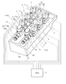
以下、添付図面に基づいて本発明の実施形態を説明する。図1に示すエンジン100は、例えば直列3気筒であって、エンジン100の運転状態に応じて一対のカム(後述)を選択的に切り替えるカム切替機構1を備えている。また、エンジン100の各気筒には、吸排気バルブの開閉動作を停止させることで、気筒を休止させる気筒休止機構2がそれぞれ設けられている。これらのカム切替機構1と気筒休止機構2は電子制御ユニット3(ECU)によって動作が制御される。
Hereinafter, embodiments of the present invention will be described with reference to the accompanying drawings. An
カム切替機構1は、吸気側カム切替機構10と、排気側カム切替機構20を備えている。吸気側カム切替機構10は、吸気カム11が設けられた吸気側二重カム軸12と、吸気側二重カム軸12をスライド移動させる吸気側スライド溝13(図3参照)及び吸気側電磁ソレノイド14とを備えている。排気側カム切替機構20は、排気カム21が設けられた排気側二重カム軸22と、排気側二重カム軸22をスライド移動させる排気側スライド溝23及び排気側電磁ソレノイド24とを備えている。これらの中で、吸気側スライド溝13及び排気側スライド溝23は、本発明に係る案内溝の一例であり、吸気側電磁ソレノイド14及び排気側電磁ソレノイド24は、本発明に係る電磁アクチュエータの一例である。
The
吸気側二重カム軸12に設けられた吸気カム11は、カムプロフィールの異なる二種類のカム(標準吸気カム15,低速カム16)を備え、排気側二重カム軸22に設けられた排気カム21は、カムプロフィールの異なる二種類のカム(早開カム25,標準排気カム26)を備えている。そして、標準吸気カム15及び早開カム25は本発明に係る第1カムの一例であり、低速カム16及び標準排気カム26は本発明に係る第2カムの一例である。
The
気筒休止機構2は、吸排気バルブを閉弁状態にすることで気筒を休止させる機構である。図2に示すように、気筒休止機構2は、ロッカーアーム51と、ブラケット52と、油圧タペット53と、ニードル54と、休止用電磁ソレノイド55とを備えている。
The
ロッカーアーム51は、吸気カム11(標準吸気カム15,低速カム16)や排気カム21(標準排気カム26,早開カム25)によって揺動されて吸気バルブV1や排気バルブV2を開弁方向に動作させる部材である。ロッカーアーム51の一端部は、ロッカーシャフト軸51Bを中心にして、ブラケット52に回動可能な状態で取り付けられている。ロッカーアーム51の他端部は、吸気バルブV1や排気バルブV2の上端に上方から当接されている。ロッカーアーム51における長手方向の途中には、吸気カム11或いは排気カム21と当接するロッカーローラ51Aが設けられている。
The
ブラケット52は、ロッカーアーム51にロッカーシャフト軸51Bでピン連結された部材であり、気筒の休止状態においてロッカーアーム51の揺動に応じて上下動される。ブラケット52の内部には、ニードル54が収納されると共にエンジンオイルで満たされるニードル収納空部52Aが形成されている。ブラケット52の下側部分は、油圧タペット53に対して進退される有底円筒状のピストン部52Bになっている。ピストン部52Bの底面中心部には、エンジンオイルの通路になると共にニードル54の先端部が挿入される油孔52Cが、板厚方向を貫通した状態で形成されている。また、ピストン部52Bの側面には、エンジンオイルで満たされた油路OLとニードル収納空部52Aとを連通する連通孔52Dが形成されている。
The
油圧タペット53は、ブラケット52のピストン部52Bが進退可能に挿入されると共に、ブラケット52(ピストン部52B)を下側から支える部材であり、円筒形のボディ53Aと、チェックボールスプリング(不図示)によって上方に付勢されるチェックボール53Bと、ピストン部52Bの下端面に下側から当接すると共に、チェックボール53B及びチェックボールスプリングを収納する有底筒状の収納部53Cと、収納部53Cを下側から支えるピストンスプリング53D等を備えている。
The
気筒の動作状態において油圧タペット53は、チェックボール53Bが上方に付勢され、チェックボール53Bによってピストン部52Bの油孔52Cが塞がれている。油孔52Cが塞がれた状態において、ピストン部52Bよりも下側を満たすエンジンオイルは流れることができない。このため、ブラケット52(ピストン部52B)は下方へ移動できず、高さ方向の位置が固定される。
In the operation state of the cylinder, in the
一方、気筒の休止状態において油圧タペット53は、ニードル54によってチェックボール53Bが下方に移動されており、ピストン部52Bの油孔52Cが開放されている。油孔52Cの開放状態において、ピストン部52Bよりも下側を満たすエンジンオイルは油孔52Cを通じてニードル収納空部52A内に流れ込むことができる。そして、ニードル収納空部52A内のエンジンオイルは、ピストン部52Bの側面に形成された連通孔52Dから油路OLへ流れ込むことができる。このため、油孔52Cが開放されると、ブラケット52(ピストン部52B)は下方への移動が可能になる。すなわち、カム11,21による押圧力がピストンスプリング53Dの復元力よりも高ければ、ピストンスプリング53Dが収縮してブラケット52が下方に移動する。そして、カム11,21による押圧力がピストンスプリング53Dの復元力よりも低くなれば、ピストンスプリング53Dの復元力によってブラケット52は上方へ移動する。
On the other hand, in the cylinder tap state, in the
ニードル54は、チェックボール53Bを下方に移動させるための棒状部材であり、ブラケット52のニードル収納空部52Aに軸方向へ移動可能な状態で収納されると共に、下端がチェックボール53Bに当接されている。ニードル54の上端部は、休止用電磁ソレノイド55の内部に収納されており、休止用電磁ソレノイド55が備えるプランジャ55Cによって上下方向に移動される。
The
休止用電磁ソレノイド55は、ガイド軸55Aと、休止用コイル55Bと、プランジャ55Cとを備えている。
The resting
ガイド軸55Aは、上端が塞がれた筒状部材であり、上端部の内側にはプランジャ55Cをニードル54の軸方向に移動可能な状態で収納するプランジャ収納空間55Dが設けられ、収納空間55Dの下方にはニードル54が軸方向に移動可能な状態で収納されるニードル収納空部55Eが設けられている。さらに、ガイド軸55Aの下端部には、ブラケット52の上端部がニードル54の軸方向へスライド移動可能な状態で嵌合されるガイド空部55Fが設けられている。
The
休止用コイル55Bは、ガイド軸55Aの上端部に配置されており、通電によって磁界を発生させてプランジャ55Cを下方に付勢する。プランジャ55Cは、ニードル54の上端に上方から当接されており、休止用コイル55Bから発生された磁界によってニードル54を下方に押し下げる。そして、休止用コイル55Bへの通電が停止されると、磁界の発生が停止されるので、チェックボールスプリングの復元力によってチェックボール53Bが上方に移動され、これに伴ってニードル54とプランジャ55Cも上方に移動される。
The resting
以上のように構成された気筒休止機構2では、気筒の動作状態において休止用電磁ソレノイド55(休止用コイル55B)は非通電状態とされ、気筒の休止状態において休止用電磁ソレノイド55は通電状態とされる。
In the
休止用電磁ソレノイド55の非通電状態では、チェックボール53Bが上方に移動されてピストン部52Bの油孔52Cが塞がれる。これにより、ブラケット52の高さ位置が固定される。そして、吸気カム11や排気カム21のカムプロフィールに沿ってロッカーローラ51Aが押圧されると、ロッカーアーム51の一端部はロッカーシャフト軸51Bを支点に回動し、他端部がバルブスプリングSPの復元力に抗して揺動し、吸気バルブV1や排気バルブV2を開閉動作させる。
When the
休止用電磁ソレノイド55の通電状態では、チェックボール53Bが下方に移動されてピストン部52Bの油孔52Cが開放される。これにより、ブラケット52が上下方向(ニードル54の軸方向)へ移動可能な状態になる。そして、吸気カム11や排気カム21のカムプロフィールに沿ってロッカーローラ51Aが押圧されると、バルブスプリングSPの復元力が強力であることから、ロッカーアーム51の他端部は吸気バルブV1の上端や排気バルブV2の上端を支点に回動し、一端部はロッカーシャフト軸51Bを介してブラケット52と共に上下方向へ揺動する。このため、ロッカーアーム51が揺動しても排気バルブV2は閉弁状態で維持される。
In the energized state of the
次に、吸気側カム切替機構10、及び、排気側カム切替機構20について説明する。ここで、排気側カム切替機構20が備える各部、排気側二重カム軸22、排気側スライド溝23,及び、排気側電磁ソレノイド24については、切り替え対象である排気カム21が、早開カム25と標準排気カム26を備えている以外は、吸気側カム切替機構10の各部と同様に構成されている。このため、以下では、吸気側カム切替機構10について説明し、排気側カム切替機構20については説明を省略する。
Next, the intake side
図3に示すように、吸気側二重カム軸12は、エンジン100の図示しないクランク軸と連動して回転する内側カム軸12Aと、内側カム軸12Aの外周とスプライン嵌合し、内側カム軸12Aに対して軸方向にスライド移動可能な外側カム軸12Bとを備えている。
As shown in FIG. 3, the intake-side
外側カム軸12Bには複数の吸気カム11が圧入され、外側カム軸12Bと一体的に回転可能な状態で取り付けられている。図1に示すように、本実施形態のエンジン100では、1つの気筒が2つの吸気バルブV1を備えているため、合計6個の吸気バルブV1及び6個の吸気カム11が設けられている。図3に示すように、各吸気カム11は、標準吸気カム15と低速カム16を備えており、外側カム軸32を内側カム軸31の軸方向にスライド移動させることで、標準吸気カム15と低速カム16の何れかが選択される。同じ気筒に対応する2つの吸気カム11は、カムプロフィールが同じ位相となるように取り付けられている。そして、3気筒であることから3組の吸気カム11は、気筒毎に位相が120°ずれた状態で取り付けられている。
A plurality of
外側カム軸12Bの端部には2条の吸気側スライド溝13(第1スライド溝13A,第2スライド溝13B)が設けられている。これらのスライド溝13A,13Bには、外側カム軸12Bを内側カム軸12Aの軸方向にスライド移動させる際に、吸気側電磁ソレノイド14が備える切替ピン41A,41Bの下端部が嵌合される(図5(B),図6(B)参照)。
Two strips of intake side slide grooves 13 (
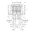
次に吸気側電磁ソレノイド14について説明する。前述したように、この吸気側電磁ソレノイド14は、本発明に係る電磁アクチュエータの一例である。図4に示すように、吸気側電磁ソレノイド14は、ケース31と、ピンガイド32と、第1切替ピン41Aと、第2切替ピン41Bと、第1電磁ソレノイド42Aと、第2電磁ソレノイド42Bとを備えている。
Next, the intake side
ケース31は、下端が開放され天井が塞がれた筒状部材であり、内部空間が第1電磁ソレノイド42Aや第2電磁ソレノイド42Bなどを収納する収納空間とされ、下端部にはフランジが形成されている。
The
ピンガイド32は、第1切替ピン41Aの軸部45Aが挿入されて案内される第1ガイド孔32Aと、第2切替ピン41Bの軸部45Bが挿入されて案内される第2ガイド孔32Bが形成された直方体ブロック状の部材である。本実施形態では、このピンガイド32をステンレス鋼によって作製している。これは、ピンガイド32が磁性を帯びることを防止し、第1切替ピン41Aや第2切替ピン41Bの各軸部45A,45Bを円滑に案内するためである。また、ピンガイド32の高さは、各軸部45A,45Bの長さよりも低く設定してあり、第1切替ピン41Aや第2切替ピン41Bが移動範囲の下端まで移動した際に、各軸部45A,45Bの一部がピンガイド32の下面よりも下方に突出されるように構成している。
The
ケース31とピンガイド32の間には下部ヨーク33が設けられている。この下部ヨーク33は、本発明に係る係止部材の一例であり、軟磁性材料で作製されている。本実施形態において、下部ヨーク33は軟鉄によって作製されている。下部ヨーク33には、第1挿入開口33Aと第2挿入開口33Bが、板厚方向を貫通した状態に形成されている。これらの挿入開口33A,33Bは、第1切替ピン41Aの軸部45Aや第2切替ピン41Bの軸部45Bの直径よりも僅かに大きく、第1切替ピン41Aの頭部44Aや第2切替ピン41Bの頭部44Bの直径よりも十分に小さい円形状に形成されている。
A
これらの第1挿入開口33A及び第2挿入開口33Bに第1切替ピン41Aや第2切替ピン41Bの各軸部45A,45Bを挿入することで、第1切替ピン41Aが移動範囲の下端に位置した際に、第1切替ピン41Aの頭部44Aは第1挿入開口33Aを通り抜けられないことから下部ヨーク33に当接する。同様に、第2切替ピン41Bが移動範囲の下端に位置した際に、第2切替ピン41Bの頭部44Bは第2挿入開口33Bを通り抜けられないことから下部ヨーク33に当接する。そして、各頭部44A,44Bのそれぞれには永久磁石43A,43Bが設けられているため、各頭部44A,44Bは、永久磁石43A,43Bからの磁力によって下部ヨーク33に吸着され、がたつきが抑制される。
By inserting the
ケース31が形成する収納空間の上部には上部ヨーク34が配置されている。この上部ヨーク34は、第1電磁ソレノイド42Aが備える第1鉄心47Aと第2電磁ソレノイド42Bが備える第2鉄心47Bとを、各鉄心47A,47Bの上端部分で連結する部材であり、軟磁性材料によって作製されている。本実施形態では、上部ヨーク34を板状の軟鉄によって作製している。この上部ヨーク34が介在することで、第1鉄心47Aと第2鉄心47Bとが一連の軟磁性体になる。
An
第1切替ピン41Aは、本発明に係る第1案内ピンの一例であり、上面にS極を励起する第1永久磁石43Aが取り付けられた第1頭部44Aと、第1頭部44Aの下面から下方に設けられた第1軸部45Aを備えている。
The
第1頭部44Aは、第1電磁ソレノイド42Aの非通電状態において第1鉄心47Aに吸着し、第1電磁ソレノイド42Aの通電状態において第1鉄心47Aから離隔される。この第1頭部44Aは肉厚の円盤状とされ、円筒状の第1ピンガイド35Aの内周面に沿って上下方向に移動する。本実施形態において第1ピンガイド35Aはステンレス鋼によって作製されている。
The first head 44A is attracted to the
第1頭部44Aにおける第1永久磁石43Aよりも上方には、第1蓋部材46Aが取り付けられている。この第1蓋部材46Aは、軟磁性体(本実施形態では板状の軟鉄)によって作製されており、第1蓋部材46Aの厚みによって第1永久磁石43Aと第1鉄心47Aとの間隔(両者間に作用する磁力の強さ)を調整している。
A
第1軸部45Aは、第1頭部44Aが第1鉄心47Aに吸着されている状態で、下側部分がピンガイド32(第1ガイド孔32A)に収納されている。また、第1切替ピン41Aが移動範囲の下端まで移動すると、下端部が第1スライド溝13A(第1案内溝の一例)に嵌合される。この嵌合状態では、第1スライド溝13Aに沿って、外側カム軸12Bが内側カム軸12Aに対してスライド移動される。
The first shaft portion 45A is housed in the pin guide 32 (
第2切替ピン41Bは、本発明に係る第2案内ピンの一例であり、上面にN極を励起する第2永久磁石43Bが取り付けられた第2頭部44Bと、第2頭部44Bの下面から下方に設けられた第2軸部45Bを備えている。
The
第2頭部44Bは、第2電磁ソレノイド42Bの非通電状態において第2鉄心47Bに吸着し、第2電磁ソレノイド42Bの通電状態において第2鉄心47Bから離隔される。この第2頭部44Bは肉厚の円盤状とされ、円筒状の第2ピンガイド35Bの内周面に沿って上下方向に移動する。本実施形態において第2ピンガイド35Bはステンレス鋼によって作製されている。
The
第2頭部44Bにおける第2永久磁石43Bよりも上方には、第2蓋部材46Bが取り付けられている。この第2蓋部材46Bは、軟磁性体(本実施形態では板状の軟鉄)によって作製されており、第2蓋部材46Bの厚みによって第2永久磁石43Bと第2鉄心47Bとの間隔(両者間に作用する磁力の強さ)を調整している。
A
第2軸部45Bは、第2頭部44Bが第2鉄心47Bに吸着されている状態で、下側部分がピンガイド32(第2ガイド孔32B)に収納されている。また、第2切替ピン41Bが移動範囲の下端まで移動すると、下端部が第2スライド溝13B(第2案内溝の一例)に嵌合される。この嵌合状態では、第2スライド溝13Bに沿って、外側カム軸12Bが内側カム軸12Aに対してスライド移動される。
The
第1電磁ソレノイド42Aは、第1鉄心47Aと、第1コイル48Aを備えている。第1鉄心47Aは第1切替ピン41Aの上方に配置され、第1コイル48Aは第1鉄心47Aの周囲に巻き付けられている。第1鉄心47Aは、軟磁性材料で作製されていることから、第1コイル48Aの非通電状態では消磁されている。そして、第1永久磁石43Aが吸着されると下端にN極が励起される。また、第1コイル48Aに通電されると、第1コイル48Aが生成する磁界によって下端にS極が励起される。
The first
第2電磁ソレノイド42Bは、第2鉄心47Bと、第2コイル48Bを備えている。第2鉄心47Bは第2切替ピン41Bの上方に配置され、第2コイル48Bは第2鉄心47Bの周囲に巻き付けられている。第2鉄心47Bは、軟磁性材料で作製されていることから、第2コイル48Bの非通電状態では消磁されている。そして、第2永久磁石43Bが吸着されると下端にS極が励起される。また、第2コイル48Bに通電されると、第2コイル48Bが生成する磁界によって下端にN極が励起される。
The second
次に、吸気側電磁ソレノイド14の動作、すなわち第1切替ピン41Aと第2切替ピン41Bを選択的に突出させる動作について説明する。この動作は、制御部の一例であるECU3によって制御される。
Next, the operation of the intake-side
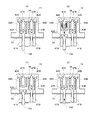
まず、第1切替ピン41Aの突出動作について説明する。図5(A)に示すように、第1コイル48Aと第2コイル48Bの非通電状態では、第1鉄心47Aの下端に第1切替ピン41Aが備える第1永久磁石43Aが吸着されていることから、第1鉄心47Aの下端にはN極が励起される。同様に、第2鉄心47Bの下端に第2切替ピン41Bが備える第2永久磁石43Bが吸着されていることから、第2鉄心47Bの下端にはS極が励起されている。加えて、第1鉄心47Aの上端部と第2鉄心47Aの上端部とが軟磁性材料で作製された上部ヨーク34で連結されていることから、第1鉄心47Aと第2鉄心47Aと上部ヨーク34が、あたかも全体で1つの磁石を構成した状態になっている。
First, the protruding operation of the
図5(B)に示すように、ECU3によって第1コイル48Aに通電がなされると、第1コイル48Aが生成する磁界によって第1鉄心47Aの下端にはS極が励起される。これにより、第1永久磁石43Aとの間で反発が生じ、第1切替ピン41Aが落下し、第1切替ピン41A(第1軸部45A)の下端部が第1スライド溝13Aに嵌合される。また、この通電状態において、第1コイル48Aが生成する磁界により、第2鉄心47Bの下端にもS極が励起される。このため、第2鉄心47Bと第2切替ピン41Bの吸着状態は維持される。
As shown in FIG. 5B, when the ECU 3 energizes the
図5(C)に示すように、第1コイル48Aへの通電が停止されると、第2永久磁石43Bの磁力によって第1鉄心47Aの下端にはN極が励起される。また、第1スライド溝13Aが浅くなることで、第1切替ピン41Aが上昇される。第1スライド溝13Aがさらに浅くなって、第1切替ピン41Aの上面が第1鉄心47Aの下端近傍まで近づくと、図5(D)に示すように、第1切替ピン41Aが第1鉄心47Aに吸着される。
As shown in FIG. 5C, when energization to the
次に、第2切替ピン41Bの突出動作について説明する。図6(A)に示すように、第1コイル48Aと第2コイル48Bの非通電状態では、図5(A)でも説明したように、第1鉄心47Aと第2鉄心47Aと上部ヨーク34が、あたかも全体で1つの磁石を構成した状態になり、第1鉄心47Aの下端に第1切替ピン41Aが吸着され、第2鉄心47Bの下端に第2切替ピン41Bが吸着される。
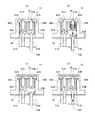
Next, the protruding operation of the
図6(B)に示すように、ECU3によって第2コイル48Bに通電がなされると、第2コイル48Bが生成する磁界によって第2鉄心47Bの下端にはN極が励起される。これにより、第2永久磁石43Bとの間で反発が生じ、第2切替ピン41Bが落下し、第2切替ピン41B(第2軸部45B)の下端部が第2スライド溝13Bに嵌合される。また、この通電状態において、第2コイル48Bが生成する磁界により、第1鉄心47Aの下端にもN極が励起される。このため、第1鉄心47Aと第1切替ピン41Aの吸着状態は維持される。
As shown in FIG. 6B, when the ECU 3 energizes the
図6(C)に示すように、第2コイル48Bへの通電が停止されると、第1永久磁石43Aの磁力によって第2鉄心47Bの下端にはS極が励起される。また、第2スライド溝13Bが浅くなることで、第2切替ピン41Bが上昇される。第2スライド溝13Bがさらに浅くなって、第2切替ピン41Bの上面が第2鉄心47Bの下端近傍まで近づくと、図6(D)に示すように、第2切替ピン41Bが第2鉄心47Bに吸着される。
As shown in FIG. 6C, when energization to the
次に、ECU3によるカムの切替制御について説明する。ここで、吸気カム11が備える標準吸気カム15と低速カム16の間の切替制御と、排気カム21が備える標準排気カム26と早開カム25の間の切替制御は同等の内容である。このため、吸気カム11での切替制御について説明することとし、排気カム21での切替制御については説明を省略する。
Next, cam switching control by the ECU 3 will be described. Here, the switching control between the
図7(A)に示すように、標準吸気カム15の選択時には、同図において左側に位置する第1切替ピン41Aが下方に移動し、第1切替ピン41Aの下端部が第1スライド溝13Aに嵌合する。吸気側二重カム軸12が回転していることから、図7(B)に示すように、外側カム軸12Bは、内側カム軸12Aに対して図における右方向へスライド移動し、吸気カム11が備える標準吸気カム15がロッカーローラ51Aに当接する。これにより、標準吸気カム15のカムプロフィールに沿ってロッカーアーム51が揺動され、吸気バルブV1が開閉動作される。
As shown in FIG. 7A, when the
図8(A)に示すように、低速カム16の選択時には、同図において右側に位置する第2切替ピン41Bが下方に移動し、第2切替ピン41Bの下端部が第2スライド溝13Bに嵌合する。吸気側二重カム軸12が回転していることから、図8(B)に示すように、外側カム軸12Bは、内側カム軸12Aに対して図における左方向へスライド移動し、吸気カム11が備える低速カム16がロッカーローラ51Aに当接する。これにより、低速カム16のカムプロフィールに沿ってロッカーアーム51が揺動され、吸気バルブV1が開閉動作される。
As shown in FIG. 8A, when the low-
以上説明したように、本実施形態の吸気側電磁ソレノイド14は、上下方向に移動可能な一対の切替ピン41A,41Bを備えており、各切替ピン41A,41Bの下端部をスライド溝13A,13Bに嵌合させることで、スライド溝13A,13Bが形成された外側カム軸12Bを、スライド溝13A,13Bに応じて移動させている。そして、第1切替ピン41Aは、上端面にS極を励起する第1永久磁石43Aを備えており、下方に移動した突出状態で第1スライド溝13Aに下端部が嵌合される。第2切替ピン41Bは、上端面にN極を励起する第2永久磁石43Bを備えており、下方に移動した突出状態で第2スライド溝13Bに下端部が嵌合される。第1電磁ソレノイド42Aが備える第1鉄心47Aは、第1切替ピン41Aの上方に配置されており、第1コイル48Aへの通電によって下端にS極が励起される。第2電磁ソレノイド42Bが備える第2鉄心47Bは、第2切替ピン41Bの上方に配置されており、第2コイル48Bへの通電によって下端にN極が励起される。
As described above, the intake-side
ECU3は、第1コイル48Aと第2コイル48Bに対して選択的に通電を行っている。そして、第1コイル48Aが通電されると、第1鉄心47Aの下端と第1永久磁石43Aが反発し、第1切替ピン41Aを選択的に第1スライド溝13Aへ嵌合させることができる。同様に、第2コイル48Bが通電されると、第2鉄心47Bの下端と第2永久磁石43Bが反発し、第2切替ピン41Bを選択的に第2スライド溝13Bへ嵌合させることができる。
The ECU 3 selectively energizes the
このように、本実施形態の吸気側電磁ソレノイド14では、切替ピン41A,41Bを落下させる期間についてコイル48A,48Bの一方に電流を流せばよいので、少ない電流量で動作させることができる。また、制御期間が短時間で済む。さらに、電磁ソレノイド42A,42Bを切替ピン41A,41Bの上方に配置すればよいので小型化にも適する。
As described above, the intake-side
以上の実施形態の説明は、本発明の理解を容易にするためのものであり、本発明を限定するものではない。本発明はその趣旨を逸脱することなく、変更、改良され得ると共に本発明にはその等価物が含まれる。 The above description of the embodiment is for facilitating the understanding of the present invention, and does not limit the present invention. The present invention can be changed and improved without departing from the gist thereof, and the present invention includes equivalents thereof.
例えば、前述の実施形態では、移動の対象物を二重カム軸が備える外側カム軸としたが、他の種類の対象物であってもよい。また、切替ピン41A,41Bの形状も前述の実施形態の形状に限られない。例えば、各軸部45A,45Bの上端に永久磁石43A,43Bを接合したものであってもよい。
For example, in the above-described embodiment, the object to be moved is the outer cam shaft included in the double cam shaft, but other types of objects may be used. Further, the shape of the switching pins 41A and 41B is not limited to the shape of the above-described embodiment. For example,
1…カム切替機構,2…気筒休止機構,3…EUC,10…吸気側カム切替機構,11…吸気カム,12…吸気側二重カム軸,12A…内側カム軸,12B…外側カム軸,13…吸気側スライド溝,13A…第1スライド溝,13B…第2スライド溝,14…吸気側電磁ソレノイド,15…標準吸気カム,16…低速カム,20…排気側カム切替機構,21…排気カム,22…排気側二重カム軸,23…排気側スライド溝,24…排気側電磁ソレノイド,25…早開カム,26…標準排気カム,31…ケース,32…ピンガイド,32A…第1ガイド孔,32B…第2ガイド孔,33…下部ヨーク,33A…第1挿入開口,33B…第2挿入開口,34…上部ヨーク,35A…第1ピンガイド,35B…第2ピンガイド,41A…第1切替ピン,41B…第2切替ピン,42A…第1電磁ソレノイド,42B…第2電磁ソレノイド,43A…第1永久磁石,43B…第2永久磁石,44A…第1頭部,44B…第2頭部,45A…第1軸部,45B…第2軸部,46A…第1蓋部材,46B…第2蓋部材,47A…第1鉄心,47B…第2鉄心,48A…第1コイル,48B…第2コイル,51…ロッカーアーム,51A…ロッカーローラ,51B…ロッカーシャフト軸,52…ブラケット,52A…ニードル収納空部,52B…ピストン部,52C…油孔,52D…連通孔,53…油圧タペット,53A…ボディ,53B…チェックボール,53C…収納部,53D…ピストンスプリング,54…ニードル,55…休止用電磁ソレノイド,55A…ガイド軸,55B…休止用コイル,55C…プランジャ,55D…プランジャ収納空間,55E…ニードル収納空部,55F…ガイド空部,100…エンジン,OL…油路,V1…吸気バルブ,V2…排気バルブ,SP…バルブスプリング
DESCRIPTION OF
Claims (5)
上端面にN極とS極の一方を励起する第1永久磁石を備え、下方に移動した突出状態で第1案内溝に下端部が嵌合される第1案内ピンと、
上端面にN極とS極の他方を励起する第2永久磁石を備え、下方に移動した突出状態で第2案内溝に下端部が嵌合される第2案内ピンと、
前記第1案内ピンの上方に配置され、第1コイルへの通電によって下端にN極とS極の一方が励起される第1鉄心と、
前記第2案内ピンの上方に配置され、第2コイルへの通電によって下端にN極とS極の他方が励起される第2鉄心と、
前記第1コイルと前記第2コイルに対して選択的に通電する制御部とを備える
電磁アクチュエータ。 An electromagnetic actuator comprising a guide pin movable in the vertical direction, and moving an object on which the guide groove is formed according to the guide groove by fitting a lower end portion of the guide pin into the guide groove. ,
A first guide pin provided with a first permanent magnet for exciting one of the N pole and the S pole on the upper end surface, the lower end portion being fitted into the first guide groove in a protruding state moved downward;
A second guide pin provided with a second permanent magnet for exciting the other of the N pole and the S pole on the upper end surface, the lower end portion being fitted in the second guide groove in a protruding state moved downward;
A first iron core disposed above the first guide pin, wherein one of the north and south poles is excited at the lower end by energizing the first coil;
A second iron core that is disposed above the second guide pin and in which the other of the N and S poles is excited at the lower end by energizing the second coil;
An electromagnetic actuator comprising: a controller that selectively energizes the first coil and the second coil.
請求項1に記載の電磁アクチュエータ。 The electromagnetic actuator according to claim 1, wherein an upper end portion of the first iron core and an upper end portion of the second iron core are connected by a soft magnetic member.
前記第2案内ピンは、前記第2永久磁石が設けられた第2頭部と、前記第2頭部の下面から下方に設けられた第2軸部とを備える
請求項1又は2に記載の電磁アクチュエータ。 The first guide pin includes a first head portion provided with the first permanent magnet, and a first shaft portion provided downward from the lower surface of the first head portion,
The said 2nd guide pin is provided with the 2nd head part in which the said 2nd permanent magnet was provided, and the 2nd axial part provided below from the lower surface of the said 2nd head part. Electromagnetic actuator.
請求項3に記載の電磁アクチュエータ。 A first insertion opening having a shape in which the first shaft portion is inserted and the first head portion is not inserted; and a second insertion opening having a shape in which the second shaft portion is inserted and the second head portion is not inserted. The electromagnetic actuator according to claim 3, further comprising a locking member formed and made of a soft magnetic material.
請求項1から4の何れか1項に記載の電磁アクチュエータ。
The object in which the guide groove is formed is splined to the outer periphery of the inner camshaft that rotates in conjunction with the crankshaft of the engine, and the first cam and the second cam having different cam profiles are provided so as to be integrally rotatable. The electromagnetic actuator according to any one of claims 1 to 4, wherein the electromagnetic actuator is an outer camshaft.
Priority Applications (1)
| Application Number | Priority Date | Filing Date | Title |
|---|---|---|---|
| JP2015117938A JP2017005123A (en) | 2015-06-11 | 2015-06-11 | Electromagnetic actuator |
Applications Claiming Priority (1)
| Application Number | Priority Date | Filing Date | Title |
|---|---|---|---|
| JP2015117938A JP2017005123A (en) | 2015-06-11 | 2015-06-11 | Electromagnetic actuator |
Publications (1)
| Publication Number | Publication Date |
|---|---|
| JP2017005123A true JP2017005123A (en) | 2017-01-05 |
Family
ID=57752276
Family Applications (1)
| Application Number | Title | Priority Date | Filing Date |
|---|---|---|---|
| JP2015117938A Pending JP2017005123A (en) | 2015-06-11 | 2015-06-11 | Electromagnetic actuator |
Country Status (1)
| Country | Link |
|---|---|
| JP (1) | JP2017005123A (en) |
Cited By (4)
| Publication number | Priority date | Publication date | Assignee | Title |
|---|---|---|---|---|
| JP2018159343A (en) * | 2017-03-23 | 2018-10-11 | トヨタ自動車株式会社 | Internal Combustion Engine System |
| WO2019057401A1 (en) * | 2017-09-21 | 2019-03-28 | Kendrion (Villingen) Gmbh | POSITIONING DEVICE WITH A SEALED GUIDE CYLINDER |
| WO2020179820A1 (en) * | 2019-03-07 | 2020-09-10 | いすゞ自動車株式会社 | Variable valve device for internal combustion engine |
| CN114255958A (en) * | 2021-11-08 | 2022-03-29 | 绵阳富临精工股份有限公司 | Electromagnetic actuator |
Citations (10)
| Publication number | Priority date | Publication date | Assignee | Title |
|---|---|---|---|---|
| DE102009006061A1 (en) * | 2009-01-24 | 2010-07-29 | Daimler Ag | Actuating device i.e. valve train actuating device, for use in internal combustion engine, has permanent magnets partially arranged between actuating components, where magnetic force of permanent magnets connects actuating components |
| JP2010530621A (en) * | 2007-06-19 | 2010-09-09 | エト・マグネティック・ゲー・エム・ベー・ハー | Electromagnetic drive device |
| US20100237264A1 (en) * | 2007-11-02 | 2010-09-23 | Markus Lengfeld | Valve operating mechanism |
| JP2011524493A (en) * | 2008-06-20 | 2011-09-01 | ダイムラー・アクチェンゲゼルシャフト | Valve drive device |
| JP2011524494A (en) * | 2008-06-20 | 2011-09-01 | ダイムラー・アクチェンゲゼルシャフト | Valve drive device |
| US20130098318A1 (en) * | 2010-06-16 | 2013-04-25 | Schaeffler Technologies AG & Co. KG | Actuator device for adjusting a sliding cam system |
| JP2013224588A (en) * | 2012-04-19 | 2013-10-31 | Toyota Motor Corp | Variable valve device |
| JP2013239538A (en) * | 2012-05-14 | 2013-11-28 | Denso Corp | Electromagnetic actuator |
| DE102012222370A1 (en) * | 2012-12-06 | 2014-06-12 | Schaeffler Technologies Gmbh & Co. Kg | Sliding cam system and sliding cam actuator with a running pin connected to a permanent magnet unit |
| JP2015102078A (en) * | 2013-11-28 | 2015-06-04 | 株式会社デンソー | Electromagnetic actuator |
-
2015
- 2015-06-11 JP JP2015117938A patent/JP2017005123A/en active Pending
Patent Citations (10)
| Publication number | Priority date | Publication date | Assignee | Title |
|---|---|---|---|---|
| JP2010530621A (en) * | 2007-06-19 | 2010-09-09 | エト・マグネティック・ゲー・エム・ベー・ハー | Electromagnetic drive device |
| US20100237264A1 (en) * | 2007-11-02 | 2010-09-23 | Markus Lengfeld | Valve operating mechanism |
| JP2011524493A (en) * | 2008-06-20 | 2011-09-01 | ダイムラー・アクチェンゲゼルシャフト | Valve drive device |
| JP2011524494A (en) * | 2008-06-20 | 2011-09-01 | ダイムラー・アクチェンゲゼルシャフト | Valve drive device |
| DE102009006061A1 (en) * | 2009-01-24 | 2010-07-29 | Daimler Ag | Actuating device i.e. valve train actuating device, for use in internal combustion engine, has permanent magnets partially arranged between actuating components, where magnetic force of permanent magnets connects actuating components |
| US20130098318A1 (en) * | 2010-06-16 | 2013-04-25 | Schaeffler Technologies AG & Co. KG | Actuator device for adjusting a sliding cam system |
| JP2013224588A (en) * | 2012-04-19 | 2013-10-31 | Toyota Motor Corp | Variable valve device |
| JP2013239538A (en) * | 2012-05-14 | 2013-11-28 | Denso Corp | Electromagnetic actuator |
| DE102012222370A1 (en) * | 2012-12-06 | 2014-06-12 | Schaeffler Technologies Gmbh & Co. Kg | Sliding cam system and sliding cam actuator with a running pin connected to a permanent magnet unit |
| JP2015102078A (en) * | 2013-11-28 | 2015-06-04 | 株式会社デンソー | Electromagnetic actuator |
Cited By (7)
| Publication number | Priority date | Publication date | Assignee | Title |
|---|---|---|---|---|
| JP2018159343A (en) * | 2017-03-23 | 2018-10-11 | トヨタ自動車株式会社 | Internal Combustion Engine System |
| WO2019057401A1 (en) * | 2017-09-21 | 2019-03-28 | Kendrion (Villingen) Gmbh | POSITIONING DEVICE WITH A SEALED GUIDE CYLINDER |
| CN111094707A (en) * | 2017-09-21 | 2020-05-01 | 肯德隆(菲林根)有限公司 | Adjustment unit with sealed guide cylinder |
| US10941678B2 (en) | 2017-09-21 | 2021-03-09 | Kendrion (Villingen) Gmbh | Adjusting device with sealed guide cylinder |
| WO2020179820A1 (en) * | 2019-03-07 | 2020-09-10 | いすゞ自動車株式会社 | Variable valve device for internal combustion engine |
| CN114255958A (en) * | 2021-11-08 | 2022-03-29 | 绵阳富临精工股份有限公司 | Electromagnetic actuator |
| CN114255958B (en) * | 2021-11-08 | 2023-07-25 | 绵阳富临精工股份有限公司 | Electromagnetic actuator |
Similar Documents
| Publication | Publication Date | Title |
|---|---|---|
| CN101689419B (en) | Electromagnetic actuating device | |
| JP5746204B2 (en) | Electromagnetic actuator | |
| US6047672A (en) | Engine valve-driving electromagnetic valve | |
| KR101512871B1 (en) | Electromagnetic actuating unit of a solenoid valve, and method for the prodution of such an actuating unit | |
| US4715330A (en) | Electromagnetically-actuated positioning mechanism | |
| CN102597435B (en) | Device for adjusting a camshaft of an internal combustion engine | |
| JP2017005123A (en) | Electromagnetic actuator | |
| JP6686454B2 (en) | Cam switching device | |
| EP1464796B1 (en) | Electromagnetic valve actuator with permanent magnet for an internal combustion engine | |
| EP3016117B1 (en) | Push pin actuator apparatus | |
| JP2018186230A (en) | Electromagnetic actuator | |
| US8517334B2 (en) | Electromagnetic valve mechanism | |
| US9551246B2 (en) | Electromagnetic actuating apparatus | |
| CN103206571A (en) | Electromagnetic valve | |
| US20070267922A1 (en) | Actuator | |
| CN109595382B (en) | Multi-actuator electromagnetic valve for controlling displacement of sliding cam | |
| US9343217B2 (en) | Electromagnetic positioning device | |
| US20200332915A1 (en) | Dual coil solenoid valve for a fuel gas control valve and the control method thereof | |
| JP6432435B2 (en) | Cam switching device | |
| JP2006057521A (en) | Solenoid valve | |
| JP2007019295A (en) | Electromagnetic actuator | |
| WO2018217536A2 (en) | Magnetic actuator for switching roller finger followers | |
| WO2012066540A3 (en) | Linear proportional valve | |
| CN110131007B (en) | Switchable cam follower for a valve train of an internal combustion engine | |
| EP1561915A3 (en) | Electromagnetic valve actuator in an internal combustion engine |
Legal Events
| Date | Code | Title | Description |
|---|---|---|---|
| A621 | Written request for application examination |
Free format text: JAPANESE INTERMEDIATE CODE: A621 Effective date: 20180605 |
|
| A977 | Report on retrieval |
Free format text: JAPANESE INTERMEDIATE CODE: A971007 Effective date: 20190125 |
|
| A131 | Notification of reasons for refusal |
Free format text: JAPANESE INTERMEDIATE CODE: A131 Effective date: 20190226 |
|
| A521 | Request for written amendment filed |
Free format text: JAPANESE INTERMEDIATE CODE: A523 Effective date: 20190425 |
|
| A02 | Decision of refusal |
Free format text: JAPANESE INTERMEDIATE CODE: A02 Effective date: 20190903 |