JP2017005128A - Temperature control method and plasma processing apparatus - Google Patents
Temperature control method and plasma processing apparatus Download PDFInfo
- Publication number
- JP2017005128A JP2017005128A JP2015118072A JP2015118072A JP2017005128A JP 2017005128 A JP2017005128 A JP 2017005128A JP 2015118072 A JP2015118072 A JP 2015118072A JP 2015118072 A JP2015118072 A JP 2015118072A JP 2017005128 A JP2017005128 A JP 2017005128A
- Authority
- JP
- Japan
- Prior art keywords
- temperature
- mounting table
- heat input
- heating mechanism
- frequency power
- Prior art date
- Legal status (The legal status is an assumption and is not a legal conclusion. Google has not performed a legal analysis and makes no representation as to the accuracy of the status listed.)
- Granted
Links
Images




Classifications
-
- H—ELECTRICITY
- H01—ELECTRIC ELEMENTS
- H01J—ELECTRIC DISCHARGE TUBES OR DISCHARGE LAMPS
- H01J37/00—Discharge tubes with provision for introducing objects or material to be exposed to the discharge, e.g. for the purpose of examination or processing thereof
- H01J37/32—Gas-filled discharge tubes
- H01J37/32431—Constructional details of the reactor
- H01J37/32458—Vessel
- H01J37/32522—Temperature
-
- H—ELECTRICITY
- H01—ELECTRIC ELEMENTS
- H01J—ELECTRIC DISCHARGE TUBES OR DISCHARGE LAMPS
- H01J37/00—Discharge tubes with provision for introducing objects or material to be exposed to the discharge, e.g. for the purpose of examination or processing thereof
- H01J37/32—Gas-filled discharge tubes
- H01J37/32431—Constructional details of the reactor
- H01J37/32715—Workpiece holder
- H01J37/32724—Temperature
-
- H—ELECTRICITY
- H10—SEMICONDUCTOR DEVICES; ELECTRIC SOLID-STATE DEVICES NOT OTHERWISE PROVIDED FOR
- H10P—GENERIC PROCESSES OR APPARATUS FOR THE MANUFACTURE OR TREATMENT OF DEVICES COVERED BY CLASS H10
- H10P50/00—Etching of wafers, substrates or parts of devices
- H10P50/20—Dry etching; Plasma etching; Reactive-ion etching
- H10P50/24—Dry etching; Plasma etching; Reactive-ion etching of semiconductor materials
- H10P50/242—Dry etching; Plasma etching; Reactive-ion etching of semiconductor materials of Group IV materials
-
- G—PHYSICS
- G05—CONTROLLING; REGULATING
- G05D—SYSTEMS FOR CONTROLLING OR REGULATING NON-ELECTRIC VARIABLES
- G05D23/00—Control of temperature
- G05D23/19—Control of temperature characterised by the use of electric means
- G05D23/20—Control of temperature characterised by the use of electric means with sensing elements having variation of electric or magnetic properties with change of temperature
-
- H—ELECTRICITY
- H01—ELECTRIC ELEMENTS
- H01J—ELECTRIC DISCHARGE TUBES OR DISCHARGE LAMPS
- H01J37/00—Discharge tubes with provision for introducing objects or material to be exposed to the discharge, e.g. for the purpose of examination or processing thereof
- H01J37/32—Gas-filled discharge tubes
- H01J37/32009—Arrangements for generation of plasma specially adapted for examination or treatment of objects, e.g. plasma sources
-
- H—ELECTRICITY
- H01—ELECTRIC ELEMENTS
- H01J—ELECTRIC DISCHARGE TUBES OR DISCHARGE LAMPS
- H01J37/00—Discharge tubes with provision for introducing objects or material to be exposed to the discharge, e.g. for the purpose of examination or processing thereof
- H01J37/32—Gas-filled discharge tubes
- H01J37/32431—Constructional details of the reactor
- H01J37/3244—Gas supply means
-
- H—ELECTRICITY
- H01—ELECTRIC ELEMENTS
- H01J—ELECTRIC DISCHARGE TUBES OR DISCHARGE LAMPS
- H01J37/00—Discharge tubes with provision for introducing objects or material to be exposed to the discharge, e.g. for the purpose of examination or processing thereof
- H01J37/32—Gas-filled discharge tubes
- H01J37/32917—Plasma diagnostics
- H01J37/32935—Monitoring and controlling tubes by information coming from the object and/or discharge
-
- H—ELECTRICITY
- H01—ELECTRIC ELEMENTS
- H01J—ELECTRIC DISCHARGE TUBES OR DISCHARGE LAMPS
- H01J37/00—Discharge tubes with provision for introducing objects or material to be exposed to the discharge, e.g. for the purpose of examination or processing thereof
- H01J37/32—Gas-filled discharge tubes
- H01J37/32917—Plasma diagnostics
- H01J37/32935—Monitoring and controlling tubes by information coming from the object and/or discharge
- H01J37/32954—Electron temperature measurement
-
- H—ELECTRICITY
- H10—SEMICONDUCTOR DEVICES; ELECTRIC SOLID-STATE DEVICES NOT OTHERWISE PROVIDED FOR
- H10P—GENERIC PROCESSES OR APPARATUS FOR THE MANUFACTURE OR TREATMENT OF DEVICES COVERED BY CLASS H10
- H10P14/00—Formation of materials, e.g. in the shape of layers or pillars
- H10P14/60—Formation of materials, e.g. in the shape of layers or pillars of insulating materials
- H10P14/65—Formation of materials, e.g. in the shape of layers or pillars of insulating materials characterised by treatments performed before or after the formation of the materials
- H10P14/6502—Formation of materials, e.g. in the shape of layers or pillars of insulating materials characterised by treatments performed before or after the formation of the materials of treatments performed before formation of the materials
- H10P14/6512—Formation of materials, e.g. in the shape of layers or pillars of insulating materials characterised by treatments performed before or after the formation of the materials of treatments performed before formation of the materials by exposure to a gas or vapour
- H10P14/6514—Formation of materials, e.g. in the shape of layers or pillars of insulating materials characterised by treatments performed before or after the formation of the materials of treatments performed before formation of the materials by exposure to a gas or vapour by exposure to a plasma
-
- H—ELECTRICITY
- H10—SEMICONDUCTOR DEVICES; ELECTRIC SOLID-STATE DEVICES NOT OTHERWISE PROVIDED FOR
- H10P—GENERIC PROCESSES OR APPARATUS FOR THE MANUFACTURE OR TREATMENT OF DEVICES COVERED BY CLASS H10
- H10P72/00—Handling or holding of wafers, substrates or devices during manufacture or treatment thereof
- H10P72/04—Apparatus for manufacture or treatment
- H10P72/0402—Apparatus for fluid treatment
- H10P72/0418—Apparatus for fluid treatment for etching
- H10P72/0421—Apparatus for fluid treatment for etching for drying etching
-
- H—ELECTRICITY
- H10—SEMICONDUCTOR DEVICES; ELECTRIC SOLID-STATE DEVICES NOT OTHERWISE PROVIDED FOR
- H10P—GENERIC PROCESSES OR APPARATUS FOR THE MANUFACTURE OR TREATMENT OF DEVICES COVERED BY CLASS H10
- H10P72/00—Handling or holding of wafers, substrates or devices during manufacture or treatment thereof
- H10P72/04—Apparatus for manufacture or treatment
- H10P72/0431—Apparatus for thermal treatment
-
- H—ELECTRICITY
- H10—SEMICONDUCTOR DEVICES; ELECTRIC SOLID-STATE DEVICES NOT OTHERWISE PROVIDED FOR
- H10P—GENERIC PROCESSES OR APPARATUS FOR THE MANUFACTURE OR TREATMENT OF DEVICES COVERED BY CLASS H10
- H10P72/00—Handling or holding of wafers, substrates or devices during manufacture or treatment thereof
- H10P72/06—Apparatus for monitoring, sorting, marking, testing or measuring
- H10P72/0602—Temperature monitoring
-
- H—ELECTRICITY
- H10—SEMICONDUCTOR DEVICES; ELECTRIC SOLID-STATE DEVICES NOT OTHERWISE PROVIDED FOR
- H10P—GENERIC PROCESSES OR APPARATUS FOR THE MANUFACTURE OR TREATMENT OF DEVICES COVERED BY CLASS H10
- H10P95/00—Generic processes or apparatus for manufacture or treatments not covered by the other groups of this subclass
- H10P95/90—Thermal treatments, e.g. annealing or sintering
-
- G—PHYSICS
- G05—CONTROLLING; REGULATING
- G05B—CONTROL OR REGULATING SYSTEMS IN GENERAL; FUNCTIONAL ELEMENTS OF SUCH SYSTEMS; MONITORING OR TESTING ARRANGEMENTS FOR SUCH SYSTEMS OR ELEMENTS
- G05B2219/00—Program-control systems
- G05B2219/30—Nc systems
- G05B2219/45—Nc applications
- G05B2219/45212—Etching, engraving, sculpturing, carving
-
- H—ELECTRICITY
- H01—ELECTRIC ELEMENTS
- H01J—ELECTRIC DISCHARGE TUBES OR DISCHARGE LAMPS
- H01J2237/00—Discharge tubes exposing object to beam, e.g. for analysis treatment, etching, imaging
- H01J2237/32—Processing objects by plasma generation
- H01J2237/33—Processing objects by plasma generation characterised by the type of processing
- H01J2237/334—Etching
Landscapes
- Physics & Mathematics (AREA)
- Engineering & Computer Science (AREA)
- Plasma & Fusion (AREA)
- Chemical & Material Sciences (AREA)
- Analytical Chemistry (AREA)
- General Physics & Mathematics (AREA)
- Automation & Control Theory (AREA)
- Drying Of Semiconductors (AREA)
- Plasma Technology (AREA)
- Control Of Temperature (AREA)
Abstract
【課題】プラズマ処理装置内にて載置台の温度制御性を高めることを目的とする。【解決手段】プラズマ処理装置内にて基板を載置する載置台の温度制御方法であって、前記プラズマ処理装置内には前記載置台を冷却する冷却機構及び該載置台を加熱する第1の加熱機構を含む温度調整機構が設けられ、前記プラズマ処理装置内に印加される高周波電力と前記載置台への入熱量との関係を示す第1の関係情報を測定により求め、予め記録部に記録したデータテーブルに基づき、所定のプロセスにて印加される高周波電力に対する第1の入熱量を算出し、前記冷却機構と前記第1の加熱機構との設定温度の差分の制御許容範囲を入熱量に応じて段階的に設定し、予め前記記録部に記憶したオペレーションマップに基づき、前記冷却機構と前記第1の加熱機構との設定温度の差分が前記第1の入熱量に応じた制御許容範囲内の温度になるように前記第1の加熱機構及び前記冷却機構の少なくともいずれかの温度を制御する、載置台の温度制御方法が提供される。【選択図】図5An object of the present invention is to improve the temperature controllability of a mounting table in a plasma processing apparatus. A temperature control method for a mounting table on which a substrate is mounted in a plasma processing apparatus, wherein the plasma processing apparatus includes a cooling mechanism for cooling the mounting table and a first heating mechanism for heating the mounting table. A temperature adjustment mechanism including a heating mechanism is provided, and first relationship information indicating a relationship between the high-frequency power applied in the plasma processing apparatus and the amount of heat input to the mounting table is obtained by measurement and recorded in the recording unit in advance. Based on the data table, the first heat input amount for the high frequency power applied in a predetermined process is calculated, and the control allowable range of the difference in the set temperature between the cooling mechanism and the first heating mechanism is set as the heat input amount. In accordance with the operation map that is set stepwise according to the operation map stored in the recording unit in advance, the difference in the set temperature between the cooling mechanism and the first heating mechanism is within the control allowable range corresponding to the first heat input amount. Temperature Controlling at least one of the temperature of the first heating mechanism and the cooling mechanism, temperature control method of the mounting table is provided so as to. [Selection] Figure 5
Description
本発明は、温度制御方法及びプラズマ処理装置に関する。 The present invention relates to a temperature control method and a plasma processing apparatus.
エッチング装置等のプラズマ処理装置において、エッチングレート等、良好なプラズマ特性を得るために基板の温度制御は重要である。そこで、基板を載置する載置台の面内の温度分布を載置台内のヒータ等により制御することで、基板の温度を制御することが行われている(例えば、特許文献1を参照)。 In a plasma processing apparatus such as an etching apparatus, it is important to control the temperature of the substrate in order to obtain good plasma characteristics such as an etching rate. Therefore, the temperature of the substrate is controlled by controlling the temperature distribution in the surface of the mounting table on which the substrate is mounted using a heater or the like in the mounting table (see, for example, Patent Document 1).
しかしながら、高周波電力を印加したとき、プラズマ処理装置内で生成されるプラズマからの入熱が不定であるためにヒータの出力が低下し、ヒータの出力値が「0」になることがある。ヒータの出力値が「0」になるとヒータの制御が不能になる。これにより、載置台の温度は、例えば高周波電力の上昇とともに上昇し、基板の温度を制御することが困難になる。 However, when high frequency power is applied, since the heat input from the plasma generated in the plasma processing apparatus is indefinite, the output of the heater may decrease and the output value of the heater may be “0”. When the output value of the heater becomes “0”, the heater cannot be controlled. As a result, the temperature of the mounting table rises, for example, with an increase in high-frequency power, making it difficult to control the temperature of the substrate.
上記課題に対して、一側面では、本発明は、プラズマ処理装置内にて載置台の温度制御性を高めることを目的とする。 In one aspect of the present invention, the object of the present invention is to improve the temperature controllability of the mounting table in the plasma processing apparatus.
上記課題を解決するために、一の態様によれば、プラズマ処理装置内にて基板を載置する載置台の温度制御方法であって、前記プラズマ処理装置内には前記載置台を冷却する冷却機構及び該載置台を加熱する第1の加熱機構を含む温度調整機構が設けられ、前記プラズマ処理装置内に印加される高周波電力と前記載置台への入熱量との関係を示す第1の関係情報を測定により求め、予め記録部に記録したデータテーブルに基づき、所定のプロセスにて印加される高周波電力に対する第1の入熱量を算出し、前記冷却機構と前記第1の加熱機構との設定温度の差分の制御許容範囲を入熱量に応じて段階的に設定し、予め前記記録部に記憶したオペレーションマップに基づき、前記冷却機構と前記第1の加熱機構との設定温度の差分が前記第1の入熱量に応じた制御許容範囲内の温度になるように前記第1の加熱機構及び前記冷却機構の少なくともいずれかの温度を制御する、載置台の温度制御方法が提供される。 In order to solve the above-described problem, according to one aspect, there is provided a temperature control method for a mounting table on which a substrate is mounted in a plasma processing apparatus, wherein cooling is performed to cool the mounting table in the plasma processing apparatus. A temperature adjustment mechanism including a mechanism and a first heating mechanism for heating the mounting table is provided, and a first relationship showing a relationship between the high frequency power applied in the plasma processing apparatus and the amount of heat input to the mounting table. Information is obtained by measurement, and based on a data table previously recorded in the recording unit, a first heat input amount for high-frequency power applied in a predetermined process is calculated, and the cooling mechanism and the first heating mechanism are set. A control allowable range of temperature difference is set stepwise according to the amount of heat input, and based on an operation map stored in advance in the recording unit, a difference in set temperature between the cooling mechanism and the first heating mechanism is 1's Controlling at least one of the temperature of the first heating mechanism and the cooling mechanism such that the temperature in the control tolerance corresponding to the amount of heat, the temperature control method of the mounting table is provided.
一の側面によれば、プラズマ処理装置内にて載置台の温度制御性を高めることができる。 According to one aspect, the temperature controllability of the mounting table can be enhanced in the plasma processing apparatus.
以下、本発明を実施するための形態について図面を参照して説明する。なお、本明細書及び図面において、実質的に同一の構成については、同一の符号を付することにより重複した説明を省く。 Hereinafter, embodiments for carrying out the present invention will be described with reference to the drawings. In addition, in this specification and drawing, about the substantially same structure, the duplicate description is abbreviate | omitted by attaching | subjecting the same code | symbol.
[プラズマ処理装置の構成例]
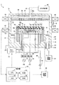
まず、本発明の一実施形態に係るプラズマ処理装置1の構成の一例について、図1を参照しながら説明する。図1に示すように、本実施形態では、プラズマ処理装置1の一例として容量結合型プラズマエッチング装置を挙げて説明する。
[Configuration example of plasma processing apparatus]
First, an example of the configuration of a plasma processing apparatus 1 according to an embodiment of the present invention will be described with reference to FIG. As shown in FIG. 1, in the present embodiment, a capacitively coupled plasma etching apparatus will be described as an example of the plasma processing apparatus 1.
プラズマ処理装置1は、例えば表面がアルマイト処理(陽極酸化処理)されたアルミニウムからなる円筒形のチャンバ10を有している。チャンバ10は、接地されている。
The plasma processing apparatus 1 has a
チャンバ10の内部には載置台12が設けられている。載置台12は、たとえばアルミニウム(Al)やチタン(Ti)、炭化ケイ素(SiC)等の材質からなり、絶縁性の保持部14を介して支持部16に支持されている。これにより、載置台12は、チャンバ10の底部に設置される。
A mounting table 12 is provided inside the
チャンバ10の底部には、排気管26が設けられ、排気管26は排気装置28に接続されている。排気装置28は、ターボ分子ポンプやドライポンプ等の真空ポンプから構成され、チャンバ10内の処理空間を所定の真空度まで減圧するとともに、チャンバ10内のガスを排気路20及び排気口24に導き、排気する。排気路20にはガスの流れを制御するためのバッフル板22が取り付けられている。
An
載置台12には、プラズマを励起するための第1高周波電源31が整合器33を介して接続され、ウェハWにプラズマ中のイオンを引き込むための第2高周波電源32が整合器34を介して接続されている。例えば、第1高周波電源31は、チャンバ10内にてプラズマを生成するために適した周波数、例えば60MHzの高周波電力HF(プラズマ励起用の高周波電力)を載置台12に印加する。第2高周波電源32は、載置台12上のウェハWにプラズマ中のイオンを引き込むのに適した低めの周波数、例えば13.56MHzの高周波電力LF(イオン引き込み用の高周波電力)を載置台12に印加する。このようにして載置台12は、ウェハWを載置するとともに、下部電極としての機能を有する。
A first high-
載置台12の上面にはウェハWを静電吸着力で保持するための静電チャック40が設けられている。静電チャック40は導電膜からなる電極40aを一対の絶縁層40b(又は絶縁シート)の間に挟み込んだものであり、電極40aには直流電圧源42がスイッチ43を介して接続されている。静電チャック40は、直流電圧源42からの電圧により、クーロン力によってウェハWを静電チャック上に吸着して保持する。静電チャック40には温度センサ77が設けられ、静電チャック40の温度を測定するようになっている。これにより、静電チャック40上のウェハWの温度が測定される。
An
静電チャック40の周縁部には、載置台12の周囲を囲むようにフォーカスリング18が配置されている。フォーカスリング18は、例えばシリコンや石英から形成されている。フォーカスリング18は、エッチングの面内均一性を高めるように機能する。
A
チャンバ10の天井部には、ガスシャワーヘッド38が接地電位の上部電極として設けられている。これにより、第1高周波電源31から出力される高周波電力が載置台12とガスシャワーヘッド38との間に容量的に印加される。
A
ガスシャワーヘッド38は、多数のガス通気孔56aを有する電極板56と、電極板56を着脱可能に支持する電極支持体58とを有する。ガス供給源62は、ガス供給配管64を介してガス導入口60aからガスシャワーヘッド38内にガスを供給する。ガスは、ガス拡散室57にて拡散され、多数のガス通気孔56aからチャンバ10内に導入される。チャンバ10の周囲には、環状または同心円状に延在する磁石66が配置され、磁力により上部電極及び下部電極間のプラズマ生成空間に生成されるプラズマを制御する。
The
静電チャック40には、ヒータ75a、75b、75c、75d、75e(以下、総称して「ヒータ75」ともいう。)が埋め込まれている。ヒータ75は、静電チャック40内に埋め込む替わりに静電チャック40の裏面に貼り付けるようにしてもよい。ヒータ75a、75b、75c、75d、75eには、給電線47を介して交流電源44から出力された電流が供給される。
In the
これにより、ヒータ75aは、載置台12のセンター部を加熱する。ヒータ75bは、載置台12のミドル部を加熱する。ヒータ75cは、載置台12のエッジ部を加熱する。ヒータ75dは、載置台12のベリーエッジ部を加熱する。ヒータ75eは、フォーカスリング18を加熱する。ヒータ75a、75b、75c、75dは、載置台12の面内を中央から順に外周側に向けて円状のゾーン(センター部(C))及び三つの環状のゾーン(ミドル部(M)、エッジ部(E)、ベリーエッジ部(VE))に分割したときのゾーン毎の加熱を可能にする。なお、ヒータ75a、75b、75c、75dは、載置台12の面内を複数のゾーンに分けてゾーン毎に加熱する第1の加熱機構の一例である。また、ヒータ75eは、フォーカスリングを加熱する第2の加熱機構の一例である。本実施形態では、載置台12の面内を4つのゾーンに分けて温度制御するが、ゾーン数は4つに限らず、1つでもよいし、2つ以上でもよい。ヒータ75の分割数は、ゾーン数及びフォーカスリング18の有無に対応させて決定することができる。また、各ゾーンの形状は、円状や環状以外であってもよい。
Thereby, the
載置台12の内部には冷媒管70が形成されている。チラーユニット71から供給された冷媒(以下、「ブライン(Brine)」ともいう。)は冷媒管70及び冷媒循環管73を循環し、載置台12を冷却する。ブラインを冷媒管70に供給する機構は、載置台12を冷却する冷却機構の一例である。
A
かかる構成により、載置台12は、ヒータ75a、75b、75c、75d、75eがそれぞれ埋め込まれたゾーン毎に独立して加熱されるとともに、所定温度のブラインが載置台12内の冷媒管70を流れることにより冷却される。これにより、ウェハWが所望の温度に調整される。また、静電チャック40の上面とウェハWの裏面との間には、伝熱ガス供給ライン72を介してヘリウム(He)ガス等の伝熱ガスが供給される。
With this configuration, the mounting table 12 is heated independently for each zone in which the
制御部50は、CPU51、ROM(Read Only Memory)52、RAM(Random Access Memory)53及びHDD(Hard Disk Drive)54を有する。CPU51は、ROM52、RAM53又はHDD54の記録部に記録されたレシピに設定された手順に従い、エッチング等のプラズマ処理を行う。また、記録部には、後述されるデータテーブル等の各種データが記録される。制御部50は、ヒータ75による加熱機構やブラインによる冷却機構の温度を制御する。
The
かかる構成のプラズマ処理装置1においてエッチング等のプラズマ処理を行う際には、まず、ウェハWが、ゲートバルブ30からチャンバ10内に搬入される。ウェハWは、静電チャック40上に載置される。ゲートバルブ30は、ウェハWを搬入後に閉じられる。チャンバ10内の圧力は、排気装置28により設定値に減圧される。静電チャック40の電極40aに直流電圧源42からの電圧を印加することで、ウェハWは、静電チャック40上に静電吸着される。
When performing plasma processing such as etching in the plasma processing apparatus 1 having such a configuration, first, the wafer W is carried into the
所定のガスがガスシャワーヘッド38からシャワー状にチャンバ10内に導入され、所定パワーのプラズマ励起用の高周波電力HFが載置台12に印加される。導入されたガスが高周波電力HFにより電離及び解離することによりプラズマが生成され、プラズマの作用によりウェハWにエッチング等のプラズマ処理が施される。載置台12には、イオン引き込み用の高周波電力LFが印加されてもよい。プラズマエッチング終了後、ウェハWはチャンバ10外に搬出される。
A predetermined gas is introduced into the
[高周波電力と入熱量との関係を示すグラフの作成例]
次に、本実施形態に係る温度制御を行うための高周波電力と入熱量との関係を示す関係式について、図2のグラフを参照しながら説明する。図2は、高周波電力と入熱量との関係を示す関係式を図示したグラフの一例を示す。高周波電力と入熱量との関係を示す関係式を図示したグラフの作成は以下の手順で行われる。
[Example of creating a graph showing the relationship between high-frequency power and heat input]
Next, a relational expression showing the relationship between the high-frequency power and the heat input for performing temperature control according to the present embodiment will be described with reference to the graph of FIG. FIG. 2 shows an example of a graph illustrating a relational expression showing the relationship between high-frequency power and heat input. Creation of a graph illustrating a relational expression showing the relationship between the high-frequency power and the heat input amount is performed according to the following procedure.
まず、プラズマ励起用の高周波電力HF及びイオン引き込み用の高周波電力LFが載置台12に印加されたときの静電チャック40の温度が温度センサ77により測定される。測定された温度は、制御部50に送信される。プラズマ励起用の高周波電力HF及びイオン引き込み用の高周波電力LFの上昇に対応して、測定された温度に応じたプラズマからの入熱量をプロットすることで、高周波電力と入熱量との関係を示すグラフが作成される。
First, the temperature of the
図2の例では、プラズマ励起用の高周波電力HF及びイオン引き込み用の高周波電力LFの合計電力値xを横軸に示し、測定された温度に応じた入熱量yを縦軸に示す。これにより、高周波電力に対する入熱量が定量化できる。図2の関係式y2=0.0097x2は、載置台12のセンター部(C),ミドル部(M),エッジ部(E),ベリーエッジ部(VE)における高周波電力x2に対する入熱量y2を示す。関係式y1=0.0112x1は、フォーカスリング18における高周波電力x1に対する入熱量y1を示す。
In the example of FIG. 2, the total power value x of the high frequency power HF for plasma excitation and the high frequency power LF for ion attraction is shown on the horizontal axis, and the amount of heat input y corresponding to the measured temperature is shown on the vertical axis. Thereby, the heat input with respect to high frequency electric power can be quantified. The relational expression y 2 = 0.0097x 2 in FIG. 2 is the amount of heat input with respect to the high-frequency power x 2 at the center (C), middle (M), edge (E), and belly edge (VE) of the mounting table 12. It shows the y 2. The relational expression y 1 = 0.0112x 1 indicates the amount of heat input y 1 with respect to the high frequency power x 1 in the
図2のR2は、関係式y1=0.0112x1、関係式y2=0.0112x2の信頼性を示す値であり、各プロットに基づき最小二乗法を用いて導いた直線y1、y2の信頼性を算出した結果を表す。R2が1に近づく程関係式y1、y2の信頼性が高いことを示す。これによれば、関係式y1、y2の信頼性が高いことがわかる。 R 2 in FIG. 2 is a value indicating the reliability of the relational expression y 1 = 0.0112x 1 and the relational expression y 2 = 0.0112x 2 , and a straight line y 1 derived using the least square method based on each plot. , Y 2 represents the result of calculating the reliability. The closer R 2 is to 1, the higher the reliability of relational expressions y 1 and y 2 . According to this, it can be seen that the relational expressions y 1 and y 2 have high reliability.
なお、図2に示す高周波電力と入熱量との関係を示す関係式y1、y2は、所定のプロセスにおけるエッチングにおいて得られた結果の一例である。そのエッチングでは、プラズマ処理装置1内の圧力が40mT(5.33Pa)に制御され、プラズマ処理装置1内に四フッ化炭素(CF4)ガス及びアルゴン(Ar)ガスが供給され、高周波電力HF,LFが印加される。このようなプロセス条件において生成されるプラズマによってエッチングが実行されたときの温度センサ77の測定値に基づき関係式y1、y2が導かれる。このように、図2の高周波電力と入熱量との関係を示す関係式は一のプロセス条件に基づき作成された高周波電力と入熱量との関係を示すにすぎない。
The relational expressions y 1 and y 2 showing the relationship between the high-frequency power and the heat input shown in FIG. 2 are examples of results obtained in etching in a predetermined process. In the etching, the pressure in the plasma processing apparatus 1 is controlled to 40 mT (5.33 Pa), carbon tetrafluoride (CF 4 ) gas and argon (Ar) gas are supplied into the plasma processing apparatus 1, and high-frequency power HF , LF are applied. Relational expressions y 1 and y 2 are derived based on the measured value of the
したがって、他のプロセス条件において、プラズマ処理装置1にてエッチングが実行されたときの温度センサ77の測定値を使用して高周波電力と入熱量との関係を示す他の関係式を導くことができる。
Therefore, another relational expression showing the relation between the high frequency power and the heat input can be derived using the measured value of the
また、高周波電力と入熱量との関係を示す関係式は、ガス種、圧力、ガス流量等のプロセス条件が異なると異なってくる。例えば、プラズマからの入熱量は、プラズマの電子密度、プラズマのイオン密度、イオンを引き込む高周波電力LF及びプラズマを生成する高周波電力HF等の値によって決まる。例えばガス種が異なると生成されるイオンの大きさが異なるため、プラズマからの入熱量が変化する。つまり、ガス種はプラズマからの入熱量を変化させる要因となる。同様に圧力もプラズマからの入熱量を変化させる要因となる。さらに、ガスシャワーヘッド38から供給するガスがホットガスである場合、ホットガスがプラズマ以外からの入熱量となる。
Further, the relational expression showing the relation between the high frequency power and the heat input amount is different when the process conditions such as the gas type, pressure, and gas flow rate are different. For example, the amount of heat input from plasma is determined by values such as plasma electron density, plasma ion density, high-frequency power LF for drawing ions, and high-frequency power HF for generating plasma. For example, the amount of heat input from the plasma changes because the size of the generated ions differs depending on the gas type. That is, the gas type becomes a factor that changes the amount of heat input from the plasma. Similarly, the pressure is a factor that changes the amount of heat input from the plasma. Furthermore, when the gas supplied from the
このため、高周波電力HF,LFと入熱量との関係を示す関係式を測定によりプロセス毎に求め、生成したデータテーブルを予め記録部に記録する。また、ホットガスの流量と入熱量との関係を示す関係式を測定により求め、生成したデータテーブルを予め記録部に記録してもよい。 Therefore, a relational expression indicating the relationship between the high frequency power HF, LF and the heat input is obtained for each process by measurement, and the generated data table is recorded in the recording unit in advance. Alternatively, a relational expression indicating the relationship between the hot gas flow rate and the heat input may be obtained by measurement, and the generated data table may be recorded in the recording unit in advance.
図2の高周波電力と入熱量との関係式y1、y2は、プラズマ励起用の高周波電力HF及びイオン引き込み用の高周波電力LFの合計電力値と入熱量との関係を示す。しかしながら、これに限らず、プラズマ励起用の高周波電力HFと入熱量との関係を示す関係式を導出してもよい。また、イオン引き込み用の高周波電力LFと入熱量との関係を示す関係式を導出してもよい。なお、本実施形態では、プラズマ励起用の高周波電力HFは載置台12に印加されるが、これに限らず、プラズマ励起用の高周波電力HFは、ガスシャワーヘッド38に印加されてもよい。
The relational expressions y 1 and y 2 between the high frequency power and the heat input in FIG. 2 indicate the relationship between the total power value of the high frequency power HF for plasma excitation and the high frequency power LF for ion attraction and the heat input. However, the present invention is not limited to this, and a relational expression indicating the relationship between the high frequency power HF for plasma excitation and the amount of heat input may be derived. Further, a relational expression indicating the relationship between the high frequency power LF for ion attraction and the amount of heat input may be derived. In the present embodiment, the high frequency power HF for plasma excitation is applied to the mounting table 12, but the present invention is not limited to this, and the high frequency power HF for plasma excitation may be applied to the
このようにして作成された高周波電力と入熱量との関係を示す関係式のデータテーブルは、本実施形態に係る温度制御方法が実行される前に収集され、記録部がRAM53又はHDD54等に保存し、管理する。データテーブルに記録される関係式y2は、プラズマ処理装置1に印加される高周波電力と載置台12への入熱量との関係を示す第1の関係情報の一例である。記録部に記録される関係式y1は、プラズマ処理装置1に印加される高周波電力とフォーカスリングへの入熱量との関係を示す第2の関係情報の一例である。
The relational data table showing the relationship between the high-frequency power and the heat input thus created is collected before the temperature control method according to the present embodiment is executed, and the recording unit is stored in the
制御部50は、記録部に記録されている多数の関係式から、次に実行するプラズマ処理のプロセス条件に合致した関係式を選択し、載置台12の温度制御に使用する。
The
実際のエッチング等のプラズマ処理において、高周波電力HF,LFがオンされた場合、関係式y1、y2にて算出される入熱量分だけヒータ75とブラインとの温度差が少なくなる。ヒータ75の出力値はブラインとヒータ75との温度差に応じて決定される。つまり、ヒータ75とブラインとの温度差が少なくなるとヒータ75の出力が低下する。ヒータ75の出力値が「0」になるとヒータ75の制御が不能になり、ウェハWの温度制御が困難になる。よって、ウェハWの温度制御が困難になることを回避するために、ヒータ75の出力値を「0」よりも大きくする必要がある。よって、本実施形態にかかる温度制御方法では、高周波電力HF,LFが印加されてヒータ75とブラインとの温度差が減少した分、ヒータ75の出力値を変更させてブラインとヒータ75との温度差を確保する。これにより、ヒータ75の出力値が「0」になることによるヒータ75の制御不能を回避できる。以下の温度制御では、前提としてブラインの温度はヒータ75の温度よりも低く制御するようになっている。
In the actual plasma processing such as etching, when the high frequency power HF and LF are turned on, the temperature difference between the
[載置台の温度制御処理例]
本実施形態にかかる温度制御方法では、ブラインとヒータ75との温度差を確保するために、ヒータ75の出力値を変更させる。本実施形態にかかる温度制御処理の一例について、図3のフローチャートを参照しながら説明する。
[Example of temperature control processing of mounting table]
In the temperature control method according to the present embodiment, the output value of the
図3の処理が開始されると、制御部50は、高周波電力と入熱量との関係式(関係情報)を記録したデータテーブルを取得する(ステップS10)。記録部に複数のデータテーブルが記録されている場合、制御部50は、次に実行するプラズマ処理のプロセス条件に合致したデータテーブルを選択する。これにより、例えば図2に示すデータテーブルが選択されたとする。
When the process of FIG. 3 is started, the
次に、制御部50は、図2に示す関係式y2=0.0112x2に基づきプロセスレシピに設定されている高周波電力HF,LFの合計電力値に対する第1の入熱量を算出する(ステップS12)。例えば、高周波電力HF,LFの合計電力値が2000Wの場合、第1の入熱量は20℃と算出される。
Next, the
図3に戻り、次に、制御部50は、ブラインとセンター部、ミドル部、エッジ部、ベリーエッジ部のヒータ75a、75b、75c、75dとの設定温度の差分が第1の入熱量に応じた温度差になるように各部のヒータ75の温度を制御する(ステップS14)。
Returning to FIG. 3, next, the
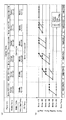
例えば、図4(a)及び(b)は、高周波電力HF,LFがオフの場合のブライン(Brine)に対するセンター部(C)、ミドル部(M)、エッジ部(E)、ベリーエッジ部(VE)及びフォーカスリングの温度制御用のオペレーションマップの一例を示す。図4(b)は、図4(a)に示したブラインとヒータ75との温度差に応じたセンター部(C)、ミドル部(M)、エッジ部(E)、ベリーエッジ部(VE)のそれぞれに取り付けられたヒータ75の温度制御範囲を示すオペレーションマップの一例である。
For example, FIGS. 4A and 4B show a center part (C), a middle part (M), an edge part (E), and a belly edge part (brine) when the high frequency powers HF and LF are off. VE) and an example of an operation map for controlling the temperature of the focus ring. 4B shows a center portion (C), a middle portion (M), an edge portion (E), and a belly edge portion (VE) corresponding to the temperature difference between the brine and the
高周波電力HF,LFがオフされている場合、プラズマからの入熱量は「0」である。この場合、図4(a)に一例を示すように、制御部50が設定する載置台12の面内のミドル部、エッジ部、ベリーエッジ部の温度は、温度センサ77により測定したセンター部とブラインとの温度差に基づき以下のように制御される。
・ミドル部の温度制御
(1)センター部の温度(C)が、ブラインの温度よりも20℃〜30℃高い場合
ミドル部の温度(M:Middle Temp.)は、センター部の温度(C:Center Temp.)よりも0℃〜20℃高い温度に制御
(2)センター部の温度(C)が、ブラインの温度よりも30℃〜40℃高い場合
ミドル部の温度(M)は、センター部の温度(C)よりも0℃〜20℃高い温度に制御(3)センター部の温度(C)が、ブラインの温度よりも40℃〜50℃高い場合
ミドル部の温度(M)は、センター部の温度(C)よりも0℃〜20℃高い温度に制御(4)センター部の温度(C)が、ブラインの温度よりも50℃〜60℃高い場合
ミドル部の温度(M)は、センター部の温度(C)よりも0℃〜20℃高い温度に制御(6)センター部の温度(C)が、ブラインの温度よりも60℃〜70℃高い場合
ミドル部の温度(M)は、センター部の温度(C)よりも0℃〜10℃高い温度に制御(7)センター部の温度(C)が、ブラインの温度よりも70℃高い場合
ミドル部の温度(M)は、センター部の温度(C)と同じ温度に制御
・エッジ部の温度制御(Edge Temp.)
上記(1)〜(7)のいずれの場合においても、以下の式に基づきエッジ部の温度(E)が制御される。
When the high frequency powers HF and LF are turned off, the amount of heat input from the plasma is “0”. In this case, as shown in an example in FIG. 4A, the temperatures of the middle part, the edge part, and the belly edge part in the surface of the mounting table 12 set by the
-Temperature control of the middle part (1) When the temperature (C) of the center part is 20 ° C to 30 ° C higher than the temperature of the brine The temperature of the middle part (M: Middle Temp.) Is the temperature of the center part (C: (2) When the temperature (C) of the center portion is 30 ° C. to 40 ° C. higher than the temperature of the brine, the temperature (M) of the middle portion is the center portion. (3) When the temperature (C) of the center portion is 40 ° C to 50 ° C higher than the temperature of the brine, the temperature (M) of the middle portion is (4) When the temperature (C) of the center part is 50 ° C. to 60 ° C. higher than the temperature of the brine, the temperature (M) of the middle part is Controlled to a
In any of the cases (1) to (7), the temperature (E) of the edge portion is controlled based on the following formula.
(3×ミドル部の温度(M)+ベリーエッジ部の温度(VE))/4
・ベリーエッジ部の温度制御
(1)センター部の温度(C)が、ブラインの温度よりも20℃〜30℃高い場合
ベリーエッジ部の温度(VE: Very Edge Temp.)は、ミドル部の温度(M)と同じ温度に制御
(2)センター部の温度(C)が、ブラインの温度よりも30℃〜40℃高い場合
ベリーエッジ部の温度(VE)は、ミドル部の温度(M)よりも0℃〜10℃高い温度に制御
(3)センター部の温度(C)が、ブラインの温度よりも40℃〜50℃高い場合
ベリーエッジ部の温度(VE)は、ミドル部の温度(M)よりも0℃〜20℃高い温度に制御
(4)センター部の温度(C)が、ブラインの温度よりも50℃〜60℃高い場合
ベリーエッジ部の温度(VE)は、ミドル部の温度(M)よりも0℃〜20℃高い温度に制御
(6)センター部の温度(C)が、ブラインの温度よりも60℃〜70℃高い場合
ベリーエッジ部の温度(VE)は、ミドル部の温度(M)よりも0℃〜10℃高い温度に制御
(7)センター部の温度(C)が、ブラインの温度よりも70℃高い場合
ベリーエッジ部の温度(VE)は、ミドル部の温度(M)と同じ温度に制御
・フォーカスリングの温度制御(Focus Ring Temp.)
ブラインの温度よりも20℃以上高い温度であって最大値が120℃になるように制御
制御部50は、センター部〜ベリーエッジ部のヒータ75a〜75dとブラインとの温度差を70℃以下に制御する。
(3 × middle part temperature (M) + berry edge part temperature (VE)) / 4
-Temperature control of the belly edge part (1) When the temperature (C) of the center part is 20 ° C to 30 ° C higher than the temperature of the brine The temperature of the belly edge part (VE: Very Edge Temp.) Is the temperature of the middle part (2) When the temperature (C) of the center part is 30 ° C. to 40 ° C. higher than the temperature of the brine The temperature (VE) of the belly edge part is higher than the temperature (M) of the middle part (3) When the temperature (C) of the center portion is 40 ° C. to 50 ° C. higher than the temperature of the brine, the temperature (VE) of the belly edge portion is the temperature of the middle portion (M (4) When the temperature (C) of the center portion is 50 ° C. to 60 ° C. higher than the temperature of the brine The temperature (VE) of the belly edge portion is the temperature of the middle portion Control to a temperature 0 to 20 ° C higher than (M) (6) When the temperature (C) of the head part is 60 ° C. to 70 ° C. higher than the temperature of the brine, the temperature (VE) of the belly edge part is controlled to a temperature 0 ° C. to 10 ° C. higher than the temperature (M) of the middle part ( 7) When the center temperature (C) is 70 ° C. higher than the brine temperature, the belly edge temperature (VE) is controlled to the same temperature as the middle temperature (M). Focus ring temperature control (Focus Ring Temp.)
Control is performed so that the maximum value is 120 ° C., which is 20 ° C. higher than the temperature of the brine. The
また、制御部50は、センター部のヒータ75aとベリーエッジ部のヒータ75dとの温度差を30℃以下に制御する。
Further, the
以上から、図4(b)のオペレーションマップに示すように、センター部(C)の基準温度に対して、ミドル部(M)、エッジ部(E)、ベリーエッジ部(VE)の温度の下限値は白丸のうちの最小値、上限値は黒丸のうちの最大値に示す範囲で各部の温度制御が行われる。 From the above, as shown in the operation map of FIG. 4B, the lower limits of the temperatures of the middle part (M), the edge part (E), and the belly edge part (VE) with respect to the reference temperature of the center part (C). The temperature control of each part is performed within the range indicated by the minimum value among the white circles and the maximum value among the black circles.
例えば、センター部の温度(C)が、ブラインの温度よりも20℃〜30℃高い場合、センター部(C)に取り付けられたヒータ75aの設定温度は、ブラインの温度よりも20℃高くなるように制御される。また、ミドル部(M)、エッジ部(E)、ベリーエッジ部(VE)のそれぞれに取り付けられたヒータ75b、75c、75dの設定温度は、ブラインの温度よりも20℃〜40℃高くなるように制御される。
For example, when the temperature (C) of the center portion is 20 ° C. to 30 ° C. higher than the temperature of the brine, the set temperature of the
また、センター部の温度(C)が、ブラインの温度よりも30℃〜40℃高い場合、センター部(C)に取り付けられたヒータ75aの設定温度は、ブラインの温度よりも30℃高くなるように制御される。また、ミドル部(M)に取り付けられたヒータ75bの設定温度は、ブラインの温度よりも30℃〜50℃高くなるように制御される。また、エッジ部(E)に取り付けられたヒータ75cの設定温度は、ブラインの温度よりも30℃〜55℃高くなるように制御される。また、ベリーエッジ部(VE)に取り付けられたヒータ75dの設定温度は、ブラインの温度よりも30℃〜60℃高くなるように制御される。
Further, when the temperature (C) of the center part is 30 ° C. to 40 ° C. higher than the temperature of the brine, the set temperature of the
しかしながら、高周波電力HF,LFがオン(印加)された場合、プラズマから載置台12への入熱量が発生するため、ヒータ75の出力が低下し、ブラインとヒータ75との温度差が小さくなり、ヒータ75の温度制御が不安定となることがある。これに対して、本実施形態では、プラズマからの入熱量に基づきヒータ75の温度を制御することでヒータ75及びブラインの温度制御の安定性を確保する。
However, when the high-frequency power HF, LF is turned on (applied), the amount of heat input from the plasma to the mounting table 12 is generated, so the output of the
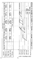
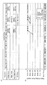
その一例として高周波電力HF,LFの合計電力値が1000Wの場合のヒータ75の温度制御方法について、図5を参照しながら説明する。図5(a)及び(b)は、高周波電力HF,LFの合計電力値が1000Wの場合のブラインに対するセンター部(C)、ミドル部(M)、エッジ部(E)、ベリーエッジ部(VE)及びフォーカスリング18の温度制御用のオペレーションマップの一例を示す。図5(b)は、図5(a)に示したブラインとヒータ75との温度差に応じたセンター部(C)、ミドル部(M)、エッジ部(E)、ベリーエッジ部(VE)のそれぞれに取り付けられたヒータ75の温度制御範囲を示すオペレーションマップの一例である。
As an example, a temperature control method for the
制御部50は、図2に示す関係式y2=0.0097x2に基づき高周波電力HF,LFの合計電力値が1000Wの場合、プラズマからの入熱量により載置台12内のヒータ75a、75b、75c、75dに入力される温度を10℃と算出する。
When the total power value of the high-frequency power HF and LF is 1000 W based on the relational expression y 2 = 0.0097x 2 shown in FIG. 2, the
この結果、制御部50は、図5(a)及び(b)に示すように、センター部(C)〜ベリーエッジ部(VE)の各部のヒータ75とブラインとの温度差を図4(a)及び(b)の高周波電力HF,LFがオフされている場合の温度差+10℃の温度差で制御する。つまり、図4に示すセンター部のヒータ75aとブラインとの温度差が10℃刻みに設定されたオペレーションマップの10℃刻みの温度制御帯を一つ右側にシフトさせた図5のオペレーションマップを生成する。これにより、制御部50は、図5のオペレーションマップを用いて、高周波電力HF,LFがオフされている場合の温度差+10℃の温度差で各部のヒータ75の温度を制御することができる。これにより、プラズマからの入熱量を考慮したヒータ75とブラインとの温度差が得られるようにヒータ75の温度が制御され、ヒータ75及びブラインの温度制御が不安定になることを回避できる。
As a result, as shown in FIGS. 5A and 5B, the
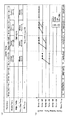
同様にして、高周波電力HF,LFの合計電力値が2000Wの場合のブラインに対するセンター部(C)〜ベリーエッジ部(VE)の温度制御用のオペレーションマップの一例を図6(a)及び(b)に示す。制御部50は、各部のヒータ75とブラインとの温度差が図4(a)及び(b)に示す高周波電力HF,LFがオフされている場合の温度差に、図2のグラフに基づき20℃を加算した値になるように各部のヒータ75の温度を制御する。その際、制御部50は、図4のオペレーションマップの10℃刻みの温度制御帯を二つ右側にシフトさせた図6のオペレーションマップを生成する。そして、制御部50は、図6のオペレーションマップに基づく設定温度に各部のヒータ75の温度を制御する。
Similarly, FIGS. 6A and 6B show an example of an operation map for temperature control of the center part (C) to the belly edge part (VE) for the brine when the total power value of the high-frequency powers HF and LF is 2000 W. ). Based on the graph of FIG. 2, the
同様にして、高周波電力HF,LFの合計電力値が3000Wの場合のブラインに対するセンター部(C)〜ベリーエッジ部(VE)の温度制御用のオペレーションマップの一例を図7(a)及び(b)に示す。制御部50は、各部のヒータ75とブラインとの温度差が図4(a)及び(b)に示す高周波電力HF,LFがオフされている場合の温度差に、図2のグラフに基づき30℃を加算した値になるように各部のヒータ75の温度を制御する。その際、制御部50は、図4のオペレーションマップの10℃刻みの温度制御帯を三つ右側にシフトさせた図7のオペレーションマップを生成する。そして、制御部50は、図7のオペレーションマップに基づく設定温度に各部のヒータ75の温度を制御する。
Similarly, FIGS. 7A and 7B show an example of an operation map for temperature control of the center part (C) to the belly edge part (VE) for the brine when the total power value of the high-frequency powers HF and LF is 3000 W. ). Based on the temperature difference when the high-frequency power HF and LF shown in FIGS. 4A and 4B are turned off, the
同様にして、高周波電力HF,LFの合計電力値が4000Wの場合のブラインに対するセンター部(C)〜ベリーエッジ部(VE)の温度制御用のオペレーションマップの一例を図8(a)及び(b)に示す。制御部50は、各部のヒータ75とブラインとの温度差が図4(a)及び(b)に示す高周波電力HF,LFがオフされている場合の温度差に、図2のグラフに基づき40℃を加算した値になるように各部のヒータ75の温度を制御する。その際、制御部50は、図4のオペレーションマップの10℃刻みの温度制御帯を四つ右側にシフトさせた図8のオペレーションマップを生成する。そして、制御部50は、図8のオペレーションマップに基づく設定温度に各部のヒータ75の温度を制御する。
Similarly, FIGS. 8A and 8B show an example of an operation map for temperature control of the center part (C) to the belly edge part (VE) for the brine when the total power value of the high-frequency powers HF and LF is 4000 W. ). Based on the temperature difference when the high-frequency power HF and LF shown in FIGS. 4A and 4B are turned off, the
これにより、ブラインとヒータ75との温度差が、高周波電力HF,LFがオフされている場合のブラインとヒータ75との温度差にプラズマからの入熱量に対応する温度を加算した値になるように各部のヒータ75の温度を制御することができる。この結果、ヒータ75とブラインとの温度差が小さくなることにより生じる制御の不安定を回避できる。
Thereby, the temperature difference between the brine and the
なお、図5〜図8に示すオペレーションマップによる温度制御の場合、図4に示す温度制御と同様に、制御部50は、センター部〜ベリーエッジ部のヒータ75a〜75dとブラインとの温度差を70℃以下に制御する。また、制御部50は、センター部のヒータ75aとベリーエッジ部のヒータ75dとの温度差を30℃以下に制御する。
In the case of the temperature control based on the operation map shown in FIGS. 5 to 8, similarly to the temperature control shown in FIG. 4, the
さらに、本実施形態では、制御部50は、図2のグラフの関係式y1=0.0112x1に基づき、高周波電力HF、LFの合計電力値に対するフォーカスリング18への入熱量を算出する。制御部50は、ブラインの温度に、算出結果に基づく温度を加算した値以上であって最大値が120℃を超えないようにフォーカスリング18の温度を制御してもよい。
Furthermore, in the present embodiment, the
図3では、ステップS16において、制御部50は、図2のグラフの関係式y1=0.0112x1に基づき、高周波電力HF、LFの合計電力値に対するフォーカスリング18への第2の入熱量を算出する。
In FIG. 3, in step S <b> 16, the
なお、図5〜図8に示すオペレーションマップによれば、高周波電力HF,LFの合計電力値が1000Wの場合、制御部50は、フォーカスリング18の温度を、ブラインの温度よりも35℃以上高い温度であって最大値が120℃になるように制御する(図5)。高周波電力HF,LFの合計電力値が2000Wの場合、制御部50は、フォーカスリング18の温度を、ブラインの温度よりも45℃以上高い温度であって最大値が120℃になるように制御する(図6)。高周波電力HF,LFの合計電力値が3000Wの場合、制御部50は、フォーカスリング18の温度を、ブラインの温度よりも55℃以上高い温度であって最大値が120℃になるように制御する(図7)。高周波電力HF,LFの合計電力値が4000Wの場合、制御部50は、フォーカスリング18の温度を、ブラインの温度よりも65℃以上高い温度であって最大値が120℃になるように制御する(図8)。
According to the operation maps shown in FIGS. 5 to 8, when the total power value of the high-frequency power HF and LF is 1000 W, the
次に、制御部50は、ブラインとフォーカスリング18のヒータ75dとの温度差が第2の入熱量に応じた温度差になるようにヒータ75dの温度を制御する(ステップS18)。そして、本処理を終了する。
Next, the
高周波電力HF,LFがオンされた場合、プラズマからの入熱量が発生するため、ヒータ75の出力が低下し、ブラインとヒータ75との温度差が小さい領域においてヒータ75の温度制御が不安定になることがある。これらの温度制御を安定させるには、従来、ヒータ75の温度とブラインの温度とを別々に制御する必要があり、煩雑であった。これに対して、本実施形態では、高周波電力と入熱量との関係を示すデータテーブルを予め作成し、高周波電力と入熱量との関係を示すデータテーブルに基づき、プラズマからの入熱量に応じたヒータ75の温度制御範囲を予想することができる。これにより、ヒータ75及びブラインの温度制御の安定性を確保できる。
When the high-frequency power HF, LF is turned on, heat input from the plasma is generated, so that the output of the
上記の実施形態では、ヒータ75とブラインとの所定以上の温度差を確保するために、ヒータ75の温度が制御された。しかしながら、制御部50は、ヒータ75の温度制御に替えてブラインの温度を制御してもよいし、ヒータ75とブラインとの温度を両方制御してもよい。つまり、ヒータ75の温度及びブラインの温度の少なくともいずれかを制御することで、ヒータ75とブラインとの温度差が小さくなりすぎないようにすることができ、プラズマからの入熱量を考慮してヒータ75及びブラインの温度制御の安定性を確保できる。
In the above embodiment, the temperature of the
ブラインの温度を制御する場合の一例としては、チラーユニット71に高温ブライン層と低温ブライン層とを設け、これらの層を切り替えることで高速にブラインの温度制御を行う方法が挙げられる。
As an example of controlling the temperature of the brine, there is a method in which the
上記の実施形態では、センター部(C)とブラインとの温度差を基準にしてオペレーションマップが生成された。しかしながら、オペレーションマップの生成は、これに限らずミドル部(M)、エッジ部(E)、ベリーエッジ部(VE)のいずれかとブラインとの温度差を基準にしてオペレーションマップを生成してもよい。オペレーションマップは、高周波電力と入熱量との関係を示す関係式から自動で生成可能である。
(入熱量との関係を示すグラフの他の例)
最後に、入熱量との関係を示す関係式を図示したグラフの他の例について説明する。図9は、高周波電力HF,LFの合計電力値とプラズマからの入熱量との関係式を図示したグラフの他の例を示す。図2は、載置台12のセンター部〜ベリーエッジ部に対する入熱量を同じとして、関係式y2により高周波電力HF,LFの合計電力値と入熱量との関係を示す。これに対して、図9は、載置台12のセンター部からエッジ部に対する入熱量を同じとして、関係式y2により高周波電力HF,LFの合計電力値と入熱量との関係を示す。ベリーエッジ部に対しては、関係式y3により高周波電力HF,LFの合計電力値と入熱量の関係が示される。これにより、ブラインの冷媒管70の位置によりセンター部〜エッジ部へのプラズマからの入熱量よりもベリーエッジ部への入熱量が高くなる場合を考慮してヒータ75の温度制御をより精度よく行うことができる。
In the above embodiment, the operation map is generated based on the temperature difference between the center portion (C) and the brine. However, the generation of the operation map is not limited to this, and the operation map may be generated based on the temperature difference between any of the middle part (M), the edge part (E), and the belly edge part (VE) and the brine. . The operation map can be automatically generated from a relational expression showing the relationship between the high frequency power and the heat input.
(Other examples of graphs showing the relationship with heat input)
Finally, another example of a graph illustrating a relational expression showing the relationship with the heat input will be described. FIG. 9 shows another example of a graph illustrating a relational expression between the total power value of the high-frequency powers HF and LF and the amount of heat input from the plasma. 2, as the same amount of heat input for the center portion-berry edge portion of the mounting table 12, shown high-frequency power HF, the relationship between the total power value and the heat input of the LF by equation y 2. In contrast, FIG. 9, as the same amount of heat input for the edge portion from the center portion of the mounting table 12, shown high-frequency power HF, the relationship between the total power value and the heat input of the LF by equation y 2. For Berry edge portion, a high frequency power HF, the relationship total power value and the amount of heat input LF represented by equation y 3. Thereby, the temperature control of the
上記の実施形態では、高周波電力HF,LFの印加によるプラズマからの入熱量の変化に基づきヒータ75の温度を制御し、他の要因による入熱量の変化は考慮しなかった。しかしながら、本実施形態の温度制御方法は、高周波電力のみならず、ホットガス等のプラズマ以外の入熱量を考慮してヒータやブラインを温度制御してもよい。この場合、ホットガス等と入熱量との関係を示すデータテーブルを予め作成し、ホットガス等と入熱量との関係を示す関係式に基づき、プラズマ以外からの入熱量に応じたヒータ75の温度制御範囲を予想することができる。上記プラズマからの入熱量に応じたヒータ75の温度制御範囲と組み合わせることで、ヒータ75及びブラインの温度制御の安定性をより確保できる。なお、ブラインとヒータ75とは、プラズマ処理装置に設けられた温度調整機構の一例である。
In the above embodiment, the temperature of the
以上、載置台の温度制御方法及びプラズマ処理装置を上記実施形態により説明したが、本発明にかかる載置台の温度制御方法及びプラズマ処理装置は上記実施形態に限定されるものではなく、本発明の範囲内で種々の変形及び改良が可能である。上記複数の実施形態に記載された事項は、矛盾しない範囲で組み合わせることができる。 The mounting table temperature control method and the plasma processing apparatus have been described in the above embodiment, but the mounting table temperature control method and the plasma processing apparatus according to the present invention are not limited to the above-described embodiment. Various modifications and improvements are possible within the scope. The matters described in the above embodiments can be combined within a consistent range.
例えば、本発明の温度制御方法は、予め導出された高周波電力やホットガスの量と入熱量との関係を示す関係式に基づき、ヒータやブラインの温度に加え、ガスシャワーヘッド38の温度、チャンバ10の内壁やデポシールドの温度制御をすることが可能である。
For example, the temperature control method of the present invention is based on a relational expression showing the relationship between the amount of high-frequency power and hot gas derived in advance and the amount of heat input, in addition to the temperature of the heater and brine, the temperature of the
本発明に係る載置台の温度制御方法は、容量結合型プラズマ(CCP:Capacitively Coupled Plasma)装置だけでなく、その他のプラズマ処理装置に適用可能である。その他のプラズマ処理装置としては、誘導結合型プラズマ(ICP:Inductively Coupled Plasma)、ラジアルラインスロットアンテナを用いたプラズマ処理装置、ヘリコン波励起型プラズマ(HWP:Helicon Wave Plasma)装置、電子サイクロトロン共鳴プラズマ(ECR:Electron Cyclotron Resonance Plasma)装置等であってもよい。 The mounting table temperature control method according to the present invention is applicable not only to a capacitively coupled plasma (CCP) apparatus but also to other plasma processing apparatuses. Other plasma processing apparatuses include inductively coupled plasma (ICP), a plasma processing apparatus using a radial line slot antenna, a helicon wave excited plasma (HWP) apparatus, an electron cyclotron resonance plasma ( An ECR (Electron Cyclotron Resonance Plasma) apparatus or the like may be used.
本明細書では、エッチング対象として半導体ウェハWについて説明したが、LCD(Liquid Crystal Display)、FPD(Flat Panel Display)等に用いられる各種基板や、フォトマスク、CD基板、プリント基板等であっても良い。 In this specification, the semiconductor wafer W has been described as an object to be etched, but various substrates used for LCD (Liquid Crystal Display), FPD (Flat Panel Display), etc., photomasks, CD substrates, printed boards, etc. good.
1:プラズマ処理装置
10:チャンバ
12:載置台(下部電極)
18:フォーカスリング
28:排気装置
31:第1高周波電力
32:第2高周波電力
38:ガスシャワーヘッド(上部電極)
40:静電チャック
44:交流電源
47:給電線
50:制御部
62:ガス供給源
70:冷媒管
71:チラーユニット
75:ヒータ
77:温度センサ
1: Plasma processing apparatus 10: Chamber 12: Mounting table (lower electrode)
18: Focus ring 28: Exhaust device 31: First high frequency power 32: Second high frequency power 38: Gas shower head (upper electrode)
40: Electrostatic chuck 44: AC power supply 47: Power supply line 50: Control unit 62: Gas supply source 70: Refrigerant pipe 71: Chiller unit 75: Heater 77: Temperature sensor
Claims (8)
前記プラズマ処理装置内には前記載置台を冷却する冷却機構及び該載置台を加熱する第1の加熱機構を含む温度調整機構が設けられ、
前記プラズマ処理装置内に印加される高周波電力と前記載置台への入熱量との関係を示す第1の関係情報を測定により求め、予め記録部に記録したデータテーブルに基づき、所定のプロセスにて印加される高周波電力に対する第1の入熱量を算出し、
前記冷却機構と前記第1の加熱機構との設定温度の差分の制御許容範囲を入熱量に応じて段階的に設定し、予め前記記録部に記憶したオペレーションマップに基づき、前記冷却機構と前記第1の加熱機構との設定温度の差分が前記第1の入熱量に応じた制御許容範囲内の温度になるように前記第1の加熱機構及び前記冷却機構の少なくともいずれかの温度を制御する、
載置台の温度制御方法。 A temperature control method of a mounting table for mounting a substrate in a plasma processing apparatus,
A temperature adjusting mechanism including a cooling mechanism for cooling the mounting table and a first heating mechanism for heating the mounting table is provided in the plasma processing apparatus,
First relationship information indicating the relationship between the high-frequency power applied to the plasma processing apparatus and the amount of heat input to the mounting table is obtained by measurement, and a predetermined process is performed based on a data table previously recorded in the recording unit. Calculating a first heat input with respect to the applied high frequency power;
A control allowable range of a difference in set temperature between the cooling mechanism and the first heating mechanism is set stepwise according to the amount of heat input, and based on an operation map stored in the recording unit in advance, the cooling mechanism and the first heating mechanism are set. Controlling the temperature of at least one of the first heating mechanism and the cooling mechanism so that a difference in set temperature with the one heating mechanism is a temperature within a control allowable range according to the first heat input amount,
Temperature control method for the mounting table.
前記記録部には、前記冷却機構と前記第1の加熱機構との設定温度の差分の制御許容範囲を入熱量に応じてゾーン毎に段階的に設定したオペレーションマップが記録され、
前記オペレーションマップに基づき、前記複数のゾーンのそれぞれに対して、前記第1の入熱量に応じた制御許容範囲内の温度になるように前記第1の加熱機構の各ゾーンの温度及び前記冷却機構の少なくともいずれかの温度を制御する、
請求項1に記載の載置台の温度制御方法。 The first heating mechanism can divide the surface of the mounting table into a plurality of zones and heat each zone.
The recording unit records an operation map in which a control allowable range of a difference in set temperature between the cooling mechanism and the first heating mechanism is set stepwise for each zone according to the amount of heat input,
Based on the operation map, for each of the plurality of zones, the temperature of each zone of the first heating mechanism and the cooling mechanism so that the temperature is within a control allowable range corresponding to the first heat input amount. Control the temperature of at least one of the
The temperature control method for the mounting table according to claim 1.
前記記録部には、前記プラズマ処理装置内に印加される高周波電力と前記フォーカスリングへの入熱量との関係を示す第2の関係情報を測定により求めたデータテーブルが記録され、
前記データテーブルに基づき、所定のプロセスにて印加される高周波電力に対する第2の入熱量を算出し、
前記オペレーションマップに基づき、前記冷却機構と前記第2の加熱機構との設定温度の差分が前記第2の入熱量に応じた制御許容範囲内の温度になるように前記第2の加熱機構及び前記冷却機構の少なくともいずれかの温度を制御する、
請求項1又は2に記載の載置台の温度制御方法。 The temperature adjustment mechanism includes a second heating mechanism that heats a focus ring that surrounds the periphery of the mounting table,
In the recording unit, a data table obtained by measuring second relationship information indicating a relationship between the high-frequency power applied in the plasma processing apparatus and the amount of heat input to the focus ring is recorded,
Based on the data table, a second heat input amount for the high frequency power applied in a predetermined process is calculated,
Based on the operation map, the second heating mechanism and the second heating mechanism and the second heating mechanism and the second heating mechanism so that a difference in set temperature between the cooling mechanism and the second heating mechanism becomes a temperature within a control allowable range according to the second heat input amount. Controlling the temperature of at least one of the cooling mechanisms,
The temperature control method of the mounting table according to claim 1 or 2.
請求項1〜3のいずれか一項に記載の載置台の温度制御方法。 Controlling the temperature of at least one of the first heating mechanism and the cooling mechanism such that the temperature difference between the first heating mechanism and the cooling mechanism is 70 ° C. or less;
The temperature control method of the mounting table as described in any one of Claims 1-3.
請求項2〜4のいずれか一項に記載の載置台の温度制御方法。 Controlling the temperature of each zone of the first heating mechanism such that the difference in temperature between the outermost zone and the innermost zone of the first heating mechanism is 30 ° C. or less.
The temperature control method of the mounting table as described in any one of Claims 2-4.
前記第1の加熱機構のエッジ部の温度が、(3×ミドル部の温度+ベリーエッジ部の温度)/4で示される温度になるように、前記第1の加熱機構のエッジ部の温度を制御する、
請求項2〜5のいずれか一項に記載の載置台の温度制御方法。 The first heating mechanism divides the surface of the mounting table from the inside to the outside of the mounting table into four zones of a center part, a middle part, an edge part, and a belly edge part, and heats each zone,
The temperature of the edge portion of the first heating mechanism is set so that the temperature of the edge portion of the first heating mechanism becomes a temperature represented by (3 × temperature of the middle portion + temperature of the belly edge portion) / 4. Control,
The temperature control method of the mounting table as described in any one of Claims 2-5.
請求項3〜6のいずれか一項に記載の載置台の温度制御方法。 Based on the operation map, the lower limit value of the difference between the set temperatures of the cooling mechanism and the second heating mechanism is a temperature within a control allowable range according to the second heat input amount, and the maximum of the difference Controlling the temperature of at least one of the second heating mechanism and the cooling mechanism so that the value does not exceed 120 ° C .;
The temperature control method of the mounting table as described in any one of Claims 3-6.
前記プラズマ処理装置内には前記載置台を冷却する冷却機構及び該載置台を加熱する第1の加熱機構を含む温度調整機構が設けられ、
前記制御部は、
前記プラズマ処理装置内に印加される高周波電力と前記載置台への入熱量との関係を示す第1の関係情報を測定により求め、予め記録部に記録したデータテーブルに基づき、所定のプロセスにて印加される高周波電力に対する第1の入熱量を算出し、
前記冷却機構と前記第1の加熱機構との設定温度の差分の制御許容範囲を入熱量に応じて段階的に設定し、予め前記記録部に記憶したオペレーションマップに基づき、前記冷却機構と前記第1の加熱機構との設定温度の差分が前記第1の入熱量に応じた制御許容範囲内の温度になるように前記第1の加熱機構及び前記冷却機構の少なくともいずれかの温度を制御する、
プラズマ処理装置。 A plasma processing apparatus having a control unit for controlling the temperature of a mounting table on which a substrate is mounted,
A temperature adjusting mechanism including a cooling mechanism for cooling the mounting table and a first heating mechanism for heating the mounting table is provided in the plasma processing apparatus,
The controller is
First relationship information indicating the relationship between the high-frequency power applied to the plasma processing apparatus and the amount of heat input to the mounting table is obtained by measurement, and a predetermined process is performed based on a data table previously recorded in the recording unit. Calculating a first heat input with respect to the applied high frequency power;
A control allowable range of a difference in set temperature between the cooling mechanism and the first heating mechanism is set stepwise according to the amount of heat input, and based on an operation map stored in the recording unit in advance, the cooling mechanism and the first heating mechanism are set. Controlling the temperature of at least one of the first heating mechanism and the cooling mechanism so that a difference in set temperature with the one heating mechanism is a temperature within a control allowable range according to the first heat input amount,
Plasma processing equipment.
Priority Applications (6)
| Application Number | Priority Date | Filing Date | Title |
|---|---|---|---|
| JP2015118072A JP6525751B2 (en) | 2015-06-11 | 2015-06-11 | Temperature control method and plasma processing apparatus |
| KR1020160068241A KR102363782B1 (en) | 2015-06-11 | 2016-06-01 | Temperature control method and plasma processing apparatus |
| US15/175,229 US10163607B2 (en) | 2015-06-11 | 2016-06-07 | Temperature control method and plasma processing apparatus |
| TW105117912A TWI707379B (en) | 2015-06-11 | 2016-06-07 | Temperature control method and plasma processing device |
| CN201610403890.XA CN106252189B (en) | 2015-06-11 | 2016-06-08 | Temprature control method and plasma processing apparatus |
| EP16173485.0A EP3104393B1 (en) | 2015-06-11 | 2016-06-08 | Temperature control method and plasma processing apparatus |
Applications Claiming Priority (1)
| Application Number | Priority Date | Filing Date | Title |
|---|---|---|---|
| JP2015118072A JP6525751B2 (en) | 2015-06-11 | 2015-06-11 | Temperature control method and plasma processing apparatus |
Publications (2)
| Publication Number | Publication Date |
|---|---|
| JP2017005128A true JP2017005128A (en) | 2017-01-05 |
| JP6525751B2 JP6525751B2 (en) | 2019-06-05 |
Family
ID=56137109
Family Applications (1)
| Application Number | Title | Priority Date | Filing Date |
|---|---|---|---|
| JP2015118072A Active JP6525751B2 (en) | 2015-06-11 | 2015-06-11 | Temperature control method and plasma processing apparatus |
Country Status (6)
| Country | Link |
|---|---|
| US (1) | US10163607B2 (en) |
| EP (1) | EP3104393B1 (en) |
| JP (1) | JP6525751B2 (en) |
| KR (1) | KR102363782B1 (en) |
| CN (1) | CN106252189B (en) |
| TW (1) | TWI707379B (en) |
Cited By (7)
| Publication number | Priority date | Publication date | Assignee | Title |
|---|---|---|---|---|
| KR20190038414A (en) | 2017-09-29 | 2019-04-08 | 도쿄엘렉트론가부시키가이샤 | Temperature control method |
| JP2019207951A (en) * | 2018-05-29 | 2019-12-05 | 東京エレクトロン株式会社 | Model generation device, model generation program and model generation method |
| WO2020004091A1 (en) * | 2018-06-29 | 2020-01-02 | 東京エレクトロン株式会社 | Plasma processing device, plasma state detection method, and plasma state detection program |
| KR20200039579A (en) * | 2018-10-05 | 2020-04-16 | 도쿄엘렉트론가부시키가이샤 | Plasma processing apparatus, monitoring method, and monitoring program |
| JP2020141116A (en) * | 2018-06-29 | 2020-09-03 | 東京エレクトロン株式会社 | Plasma processing equipment, plasma state detection method and plasma state detection program |
| KR20220059422A (en) * | 2020-11-02 | 2022-05-10 | 도쿄엘렉트론가부시키가이샤 | Recipe updating method |
| JP2023522349A (en) * | 2020-04-20 | 2023-05-30 | ラム リサーチ コーポレーション | Enhanced closed-loop gas-based heat exchange |
Families Citing this family (6)
| Publication number | Priority date | Publication date | Assignee | Title |
|---|---|---|---|---|
| TWI829367B (en) * | 2017-11-16 | 2024-01-11 | 日商東京威力科創股份有限公司 | Plasma processing apparatus, temperature control method, and temperature control program |
| CN111009454B (en) * | 2018-10-05 | 2024-05-17 | 东京毅力科创株式会社 | Plasma processing apparatus, monitoring method, and recording medium |
| KR102135110B1 (en) * | 2018-11-30 | 2020-07-17 | 세메스 주식회사 | Apparatus for treating substrate and method for controlling temperature of gas distribution plate |
| CN111856891A (en) * | 2020-08-17 | 2020-10-30 | 上海集成电路研发中心有限公司 | Temperature Compensation Device for Optimizing the Thermal Effect of Workpiece Stage in Lithography Equipment |
| JP7575830B1 (en) * | 2024-07-31 | 2024-10-30 | 株式会社大橋製作所 | Mounting Equipment |
| CN120406617A (en) * | 2025-04-27 | 2025-08-01 | 西安微电子技术研究所 | A constant temperature control system for a circuit module |
Citations (4)
| Publication number | Priority date | Publication date | Assignee | Title |
|---|---|---|---|---|
| JP2006269944A (en) * | 2005-03-25 | 2006-10-05 | Tokyo Electron Ltd | Temperature adjusting method, temperature adjusting device, plasma processing device |
| JP2008177285A (en) * | 2007-01-17 | 2008-07-31 | Hitachi High-Technologies Corp | Plasma processing equipment |
| JP2011187758A (en) * | 2010-03-10 | 2011-09-22 | Tokyo Electron Ltd | Temperature control system, temperature control method, plasma treatment device, and computer storage medium |
| JP2013172013A (en) * | 2012-02-21 | 2013-09-02 | Tokyo Electron Ltd | Substrate processing apparatus, substrate processing method, and method of changing substrate temperature settable band |
Family Cites Families (9)
| Publication number | Priority date | Publication date | Assignee | Title |
|---|---|---|---|---|
| JPH04196528A (en) * | 1990-11-28 | 1992-07-16 | Toshiba Corp | Magnetron etching system |
| JP4256031B2 (en) | 1999-07-27 | 2009-04-22 | 東京エレクトロン株式会社 | Processing apparatus and temperature control method thereof |
| JP4838197B2 (en) * | 2007-06-05 | 2011-12-14 | 東京エレクトロン株式会社 | Plasma processing apparatus, electrode temperature adjusting apparatus, electrode temperature adjusting method |
| JP5358956B2 (en) * | 2008-01-19 | 2013-12-04 | 東京エレクトロン株式会社 | Mounting table device, processing device, temperature control method, and storage medium |
| JP5762704B2 (en) * | 2010-08-20 | 2015-08-12 | 東京エレクトロン株式会社 | Substrate processing apparatus and temperature control method |
| JP5732941B2 (en) * | 2011-03-16 | 2015-06-10 | 東京エレクトロン株式会社 | Plasma etching apparatus and plasma etching method |
| JP5897275B2 (en) * | 2011-07-25 | 2016-03-30 | 東京エレクトロン株式会社 | Temperature control unit, substrate mounting table, substrate processing apparatus, temperature control system, and substrate processing method |
| JP5973731B2 (en) * | 2012-01-13 | 2016-08-23 | 東京エレクトロン株式会社 | Plasma processing apparatus and heater temperature control method |
| JP2015099824A (en) * | 2013-11-18 | 2015-05-28 | 株式会社東芝 | Substrate processing apparatus and control method |
-
2015
- 2015-06-11 JP JP2015118072A patent/JP6525751B2/en active Active
-
2016
- 2016-06-01 KR KR1020160068241A patent/KR102363782B1/en active Active
- 2016-06-07 US US15/175,229 patent/US10163607B2/en active Active
- 2016-06-07 TW TW105117912A patent/TWI707379B/en active
- 2016-06-08 CN CN201610403890.XA patent/CN106252189B/en active Active
- 2016-06-08 EP EP16173485.0A patent/EP3104393B1/en active Active
Patent Citations (4)
| Publication number | Priority date | Publication date | Assignee | Title |
|---|---|---|---|---|
| JP2006269944A (en) * | 2005-03-25 | 2006-10-05 | Tokyo Electron Ltd | Temperature adjusting method, temperature adjusting device, plasma processing device |
| JP2008177285A (en) * | 2007-01-17 | 2008-07-31 | Hitachi High-Technologies Corp | Plasma processing equipment |
| JP2011187758A (en) * | 2010-03-10 | 2011-09-22 | Tokyo Electron Ltd | Temperature control system, temperature control method, plasma treatment device, and computer storage medium |
| JP2013172013A (en) * | 2012-02-21 | 2013-09-02 | Tokyo Electron Ltd | Substrate processing apparatus, substrate processing method, and method of changing substrate temperature settable band |
Cited By (23)
| Publication number | Priority date | Publication date | Assignee | Title |
|---|---|---|---|---|
| US10615008B2 (en) | 2017-09-29 | 2020-04-07 | Tokyo Electron Limited | Temperature control method |
| KR20190038414A (en) | 2017-09-29 | 2019-04-08 | 도쿄엘렉트론가부시키가이샤 | Temperature control method |
| JP7018823B2 (en) | 2018-05-29 | 2022-02-14 | 東京エレクトロン株式会社 | Model generator, model generator and model generation method |
| JP2019207951A (en) * | 2018-05-29 | 2019-12-05 | 東京エレクトロン株式会社 | Model generation device, model generation program and model generation method |
| KR20190135938A (en) | 2018-05-29 | 2019-12-09 | 도쿄엘렉트론가부시키가이샤 | Model generation apparatus, model generation program, and model generation method |
| US11424102B2 (en) | 2018-05-29 | 2022-08-23 | Tokyo Electron Limited | Model generation apparatus, model generation program, and model generation method |
| TWI811366B (en) * | 2018-05-29 | 2023-08-11 | 日商東京威力科創股份有限公司 | Model generation apparatus, model generation program, and model generation method |
| TWI882440B (en) * | 2018-06-29 | 2025-05-01 | 日商東京威力科創股份有限公司 | Plasma processing device, plasma state detection method and plasma state detection program |
| JP2020141116A (en) * | 2018-06-29 | 2020-09-03 | 東京エレクトロン株式会社 | Plasma processing equipment, plasma state detection method and plasma state detection program |
| JP7527342B2 (en) | 2018-06-29 | 2024-08-02 | 東京エレクトロン株式会社 | Plasma processing apparatus, plasma state detection method, and plasma state detection program |
| WO2020004091A1 (en) * | 2018-06-29 | 2020-01-02 | 東京エレクトロン株式会社 | Plasma processing device, plasma state detection method, and plasma state detection program |
| JP7202972B2 (en) | 2018-06-29 | 2023-01-12 | 東京エレクトロン株式会社 | PLASMA PROCESSING APPARATUS, PLASMA STATE DETECTION METHOD AND PLASMA STATE DETECTION PROGRAM |
| JP2023033331A (en) * | 2018-06-29 | 2023-03-10 | 東京エレクトロン株式会社 | PLASMA PROCESSING APPARATUS, PLASMA STATE DETECTION METHOD AND PLASMA STATE DETECTION PROGRAM |
| KR20200039579A (en) * | 2018-10-05 | 2020-04-16 | 도쿄엘렉트론가부시키가이샤 | Plasma processing apparatus, monitoring method, and monitoring program |
| JP2023099617A (en) * | 2018-10-05 | 2023-07-13 | 東京エレクトロン株式会社 | Plasma processing apparatus, monitoring method and monitoring program |
| JP7280113B2 (en) | 2018-10-05 | 2023-05-23 | 東京エレクトロン株式会社 | PLASMA PROCESSING APPARATUS, MONITORING METHOD AND MONITORING PROGRAM |
| JP7561913B2 (en) | 2018-10-05 | 2024-10-04 | 東京エレクトロン株式会社 | Plasma processing apparatus, monitoring method and monitoring program |
| KR102733735B1 (en) * | 2018-10-05 | 2024-11-22 | 도쿄엘렉트론가부시키가이샤 | Plasma processing apparatus, monitoring method, and monitoring program |
| JP2020061353A (en) * | 2018-10-05 | 2020-04-16 | 東京エレクトロン株式会社 | Plasma processing apparatus, monitoring method, and monitoring program |
| JP2023522349A (en) * | 2020-04-20 | 2023-05-30 | ラム リサーチ コーポレーション | Enhanced closed-loop gas-based heat exchange |
| US12368057B2 (en) | 2020-04-20 | 2025-07-22 | Lam Research Corporation | Enhanced closed loop gas based heat exchange |
| KR20220059422A (en) * | 2020-11-02 | 2022-05-10 | 도쿄엘렉트론가부시키가이샤 | Recipe updating method |
| KR102888083B1 (en) | 2020-11-02 | 2025-11-18 | 도쿄엘렉트론가부시키가이샤 | Recipe updating method |
Also Published As
| Publication number | Publication date |
|---|---|
| CN106252189B (en) | 2018-01-30 |
| KR102363782B1 (en) | 2022-02-15 |
| EP3104393A1 (en) | 2016-12-14 |
| CN106252189A (en) | 2016-12-21 |
| JP6525751B2 (en) | 2019-06-05 |
| KR20160146534A (en) | 2016-12-21 |
| EP3104393B1 (en) | 2018-12-12 |
| TWI707379B (en) | 2020-10-11 |
| US10163607B2 (en) | 2018-12-25 |
| TW201717248A (en) | 2017-05-16 |
| US20160365229A1 (en) | 2016-12-15 |
Similar Documents
| Publication | Publication Date | Title |
|---|---|---|
| JP6525751B2 (en) | Temperature control method and plasma processing apparatus | |
| KR102542777B1 (en) | Member having coolant path, control method of member having coolant path, and substrate processing apparatus | |
| CN110010439B (en) | Plasma etching apparatus and plasma etching method | |
| JP6100672B2 (en) | Temperature control mechanism, temperature control method, and substrate processing apparatus | |
| JP6385915B2 (en) | Etching method | |
| JP5973731B2 (en) | Plasma processing apparatus and heater temperature control method | |
| CN110544614B (en) | Model generation device, model generation method, and recording medium | |
| JP6498152B2 (en) | Etching method | |
| JP2018098239A (en) | Mounting table and plasma processing apparatus | |
| JP2020009839A (en) | Plasma etching method and plasma etching apparatus | |
| TWI799602B (en) | Plasma treatment device and plasma etching method | |
| JP2011187758A (en) | Temperature control system, temperature control method, plasma treatment device, and computer storage medium | |
| TW201903888A (en) | Plasma processing apparatus and plasma control method | |
| JP2011119708A (en) | Substrate holding device and plasma processing device | |
| JP2018195846A (en) | Etching apparatus | |
| JP2019067846A (en) | Temperature control method | |
| JP2017212051A (en) | Plasma processing method | |
| TW201937594A (en) | Plasma processing method | |
| JP5097074B2 (en) | Plasma processing apparatus and plasma processing method | |
| JP7582749B2 (en) | Temperature control method and temperature control device | |
| WO2024070267A1 (en) | Substrate processing device and substrate processing method |
Legal Events
| Date | Code | Title | Description |
|---|---|---|---|
| A621 | Written request for application examination |
Free format text: JAPANESE INTERMEDIATE CODE: A621 Effective date: 20180305 |
|
| A977 | Report on retrieval |
Free format text: JAPANESE INTERMEDIATE CODE: A971007 Effective date: 20190129 |
|
| A131 | Notification of reasons for refusal |
Free format text: JAPANESE INTERMEDIATE CODE: A131 Effective date: 20190205 |
|
| A521 | Request for written amendment filed |
Free format text: JAPANESE INTERMEDIATE CODE: A523 Effective date: 20190322 |
|
| TRDD | Decision of grant or rejection written | ||
| A01 | Written decision to grant a patent or to grant a registration (utility model) |
Free format text: JAPANESE INTERMEDIATE CODE: A01 Effective date: 20190409 |
|
| A61 | First payment of annual fees (during grant procedure) |
Free format text: JAPANESE INTERMEDIATE CODE: A61 Effective date: 20190507 |
|
| R150 | Certificate of patent or registration of utility model |
Ref document number: 6525751 Country of ref document: JP Free format text: JAPANESE INTERMEDIATE CODE: R150 |
|
| R250 | Receipt of annual fees |
Free format text: JAPANESE INTERMEDIATE CODE: R250 |
|
| R250 | Receipt of annual fees |
Free format text: JAPANESE INTERMEDIATE CODE: R250 |
|
| R250 | Receipt of annual fees |
Free format text: JAPANESE INTERMEDIATE CODE: R250 |
|
| R250 | Receipt of annual fees |
Free format text: JAPANESE INTERMEDIATE CODE: R250 |
|
| R250 | Receipt of annual fees |
Free format text: JAPANESE INTERMEDIATE CODE: R250 |