KR102733735B1 - Plasma processing apparatus, monitoring method, and monitoring program - Google Patents
Plasma processing apparatus, monitoring method, and monitoring program Download PDFInfo
- Publication number
- KR102733735B1 KR102733735B1 KR1020190121937A KR20190121937A KR102733735B1 KR 102733735 B1 KR102733735 B1 KR 102733735B1 KR 1020190121937 A KR1020190121937 A KR 1020190121937A KR 20190121937 A KR20190121937 A KR 20190121937A KR 102733735 B1 KR102733735 B1 KR 102733735B1
- Authority
- KR
- South Korea
- Prior art keywords
- temperature
- heater
- plasma
- change
- processing
- Prior art date
- Legal status (The legal status is an assumption and is not a legal conclusion. Google has not performed a legal analysis and makes no representation as to the accuracy of the status listed.)
- Active
Links
Images


Classifications
-
- H—ELECTRICITY
- H01—ELECTRIC ELEMENTS
- H01J—ELECTRIC DISCHARGE TUBES OR DISCHARGE LAMPS
- H01J37/00—Discharge tubes with provision for introducing objects or material to be exposed to the discharge, e.g. for the purpose of examination or processing thereof
- H01J37/32—Gas-filled discharge tubes
- H01J37/32917—Plasma diagnostics
- H01J37/32935—Monitoring and controlling tubes by information coming from the object and/or discharge
-
- H—ELECTRICITY
- H01—ELECTRIC ELEMENTS
- H01J—ELECTRIC DISCHARGE TUBES OR DISCHARGE LAMPS
- H01J37/00—Discharge tubes with provision for introducing objects or material to be exposed to the discharge, e.g. for the purpose of examination or processing thereof
- H01J37/32—Gas-filled discharge tubes
- H01J37/32431—Constructional details of the reactor
- H01J37/32715—Workpiece holder
- H01J37/32724—Temperature
Landscapes
- Physics & Mathematics (AREA)
- Engineering & Computer Science (AREA)
- Plasma & Fusion (AREA)
- Chemical & Material Sciences (AREA)
- Analytical Chemistry (AREA)
- Drying Of Semiconductors (AREA)
- Plasma Technology (AREA)
Abstract
(과제) 센서를 배치하는 일 없이 이상의 발생을 검출하는 것.
(해결 수단) 플라즈마 처리 장치는, 기억부와, 제 2 취득부와, 감시부를 갖는다. 기억부는, 탑재대에 탑재된 웨이퍼에 대한 플라즈마 처리의 처리 조건이 변화한 경우의 탑재대의 온도에 관한 값의 변화를 나타낸 변화 정보를 기억한다. 제 2 취득부는, 탑재대의 온도에 관한 값을 소정의 사이클로 취득한다. 감시부는, 변화 정보에 근거하여, 제 2 취득부에 의해 취득되는 탑재대의 온도에 관한 값의 변화로부터 플라즈마 처리의 처리 조건의 변화를 감시한다.(Task) Detecting the occurrence of an abnormality without placing sensors.
(Solution) A plasma processing device has a memory unit, a second acquisition unit, and a monitoring unit. The memory unit stores change information indicating a change in a value related to the temperature of the mounting table when a processing condition for plasma processing for a wafer mounted on the mounting table changes. The second acquisition unit acquires a value related to the temperature of the mounting table in a predetermined cycle. The monitoring unit monitors a change in the processing condition for plasma processing from a change in the value related to the temperature of the mounting table acquired by the second acquisition unit based on the change information.
Description
본 개시는, 플라즈마 처리 장치, 감시 방법 및 감시 프로그램에 관한 것이다.The present disclosure relates to a plasma processing device, a monitoring method, and a monitoring program.
특허문헌 1에는, 고주파 전원으로부터 정합기를 거쳐서 처리실에 공급되는 고주파 전력의 정합기에서의 입력 전력의 값과 전력 설정치의 차이를 구하고, 정합기의 입력 전력의 값이 전력 설정치가 되도록 고주파 전원의 출력 전력을 제어하는 기술이 제안되어 있다.
본 개시는, 센서를 배치하는 일 없이 이상의 발생을 검출할 수 있는 기술을 제공한다.The present disclosure provides a technique capable of detecting the occurrence of an abnormality without deploying a sensor.
본 개시의 일 태양에 따른 플라즈마 처리 장치는, 기억부와, 취득부와, 감시부를 갖는다. 기억부는, 탑재대에 탑재된 피처리체에 대한 플라즈마 처리의 처리 조건이 변화한 경우의 탑재대의 온도에 관한 값의 변화를 나타낸 변화 정보를 기억한다. 취득부는, 탑재대의 온도에 관한 값을 소정의 사이클로 취득한다. 감시부는, 변화 정보에 근거하여, 취득부에 의해 취득되는 탑재대의 온도에 관한 값의 변화로부터 플라즈마 처리의 처리 조건의 변화를 감시한다.A plasma processing device according to one aspect of the present disclosure has a memory unit, an acquisition unit, and a monitoring unit. The memory unit stores change information indicating a change in a temperature value of a mounting platform when a processing condition for plasma processing for a processing target mounted on a mounting platform changes. The acquisition unit acquires a temperature value of the mounting platform in a predetermined cycle. The monitoring unit monitors a change in a processing condition for plasma processing from a change in the temperature value of the mounting platform acquired by the acquisition unit based on the change information.
본 개시에 따르면, 센서를 배치하는 일 없이 이상의 발생을 검출할 수 있다.According to the present disclosure, the occurrence of an abnormality can be detected without placing a sensor.
도 1은 실시 형태와 관련되는 플라즈마 처리 장치를 개략적으로 나타내는 도면이다.
도 2는 실시 형태와 관련되는 탑재대를 나타내는 평면도이다.
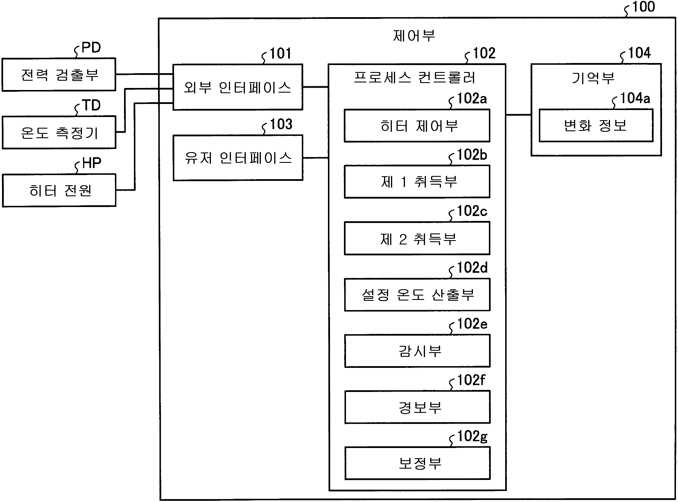
도 3은 실시 형태와 관련되는 플라즈마 처리 장치를 제어하는 제어부의 개략적인 구성을 나타낸 블록도이다.
도 4는 웨이퍼의 온도에 영향을 주는 에너지의 흐름을 모식적으로 나타내는 도면이다.
도 5a는 미점화 상태의 에너지의 흐름을 모식적으로 나타내는 도면이다.
도 5b는 점화 상태의 에너지의 흐름을 모식적으로 나타내는 도면이다.
도 6은 웨이퍼의 온도와 히터로의 공급 전력의 변화의 일례를 나타내는 도면이다.
도 7은 점화 상태의 에너지의 흐름을 모식적으로 나타내는 도면이다.
도 8a는 상부 전극, 퇴적물 실드의 온도가 변화한 경우의 히터로부터의 발열량의 변화의 일례를 나타낸 도면이다.
도 8b는 제 1 고주파 전력, 제 2 고주파 전력이 변화한 경우의 히터로부터의 발열량의 변화의 일례를 나타낸 도면이다.
도 8c는 처리 용기 내의 압력이 변화한 경우의 히터로부터의 발열량의 변화의 일례를 나타낸 도면이다.
도 8d는 전열 가스의 압력, 웨이퍼 W의 이면 막 두께가 변화한 경우의 열저항의 변화의 일례를 나타낸 도면이다.
도 9는 실시 형태와 관련되는 생성 처리의 흐름의 일례를 나타내는 플로차트이다.
도 10은 실시 형태와 관련되는 감시 처리의 흐름의 일례를 나타내는 플로차트이다.
도 11a는 다른 실시 형태와 관련되는 탑재대를 나타내는 평면도이다.
도 11b는 다른 실시 형태와 관련되는 탑재대를 나타내는 평면도이다.
도 11c는 다른 실시 형태와 관련되는 탑재대를 나타내는 평면도이다.Figure 1 is a drawing schematically showing a plasma processing device related to an embodiment.
Figure 2 is a plan view showing a mounting platform related to the embodiment.
Figure 3 is a block diagram showing a schematic configuration of a control unit that controls a plasma processing device related to an embodiment.
Figure 4 is a diagram schematically showing the flow of energy that affects the temperature of the wafer.
Figure 5a is a diagram schematically showing the flow of energy in an unignited state.
Figure 5b is a diagram schematically showing the flow of energy in the ignition state.
Figure 6 is a diagram showing an example of changes in the temperature of a wafer and the power supplied to the heater.
Figure 7 is a diagram schematically showing the flow of energy in an ignition state.
Figure 8a is a drawing showing an example of a change in the amount of heat generated from a heater when the temperature of the upper electrode and the sediment shield changes.
Figure 8b is a drawing showing an example of a change in the amount of heat generated from a heater when the first high-frequency power and the second high-frequency power are changed.
Figure 8c is a drawing showing an example of a change in the amount of heat generated from a heater when the pressure inside the processing vessel changes.
Figure 8d is a drawing showing an example of a change in thermal resistance when the pressure of the heating gas and the thickness of the backside film of the wafer W are changed.
Figure 9 is a flowchart showing an example of the flow of generation processing related to the embodiment.
Figure 10 is a flowchart showing an example of the flow of surveillance processing related to the embodiment.
Figure 11a is a plan view showing a mounting platform related to another embodiment.
Figure 11b is a plan view showing a mounting platform related to another embodiment.
Figure 11c is a plan view showing a mounting platform related to another embodiment.
이하, 도면을 참조하여 본원이 개시하는 플라즈마 처리 장치, 감시 방법 및 감시 프로그램의 실시 형태에 대하여 상세하게 설명한다. 본 개시에 있어서는, 플라즈마 처리 장치의 구체적인 예로서, 플라즈마 에칭을 행하는 장치를 예로 들어 상세하게 설명한다. 또, 본 실시 형태에 의해, 개시하는 플라즈마 처리 장치, 감시 방법 및 감시 프로그램이 한정되는 것이 아니다.Hereinafter, with reference to the drawings, embodiments of the plasma processing device, the monitoring method, and the monitoring program disclosed in the present invention will be described in detail. In the present disclosure, a specific example of the plasma processing device is a device that performs plasma etching, and this will be described in detail. In addition, the plasma processing device, the monitoring method, and the monitoring program disclosed in the present embodiment are not limited thereto.
그런데, 예컨대, 플라즈마 처리 장치에는, 처리 용기 내에 각종 프로브나 각종 전기 센서 등의 센서를 배치하여 센서에서 플라즈마의 상태를 검출하고, 플라즈마의 상태의 변화로부터 이상의 발생을 검출하는 것이 있다. 그러나, 플라즈마 처리 장치는, 처리 용기 내에 센서를 배치하면, 제조 비용이 상승한다. 또한, 플라즈마 처리 장치는, 처리 용기 내에 센서를 배치하면, 센서가 특이점이 되고, 특이점의 주위에서 플라즈마 처리의 균일성이 저하된다. 그래서, 플라즈마 처리 장치에서는, 센서를 배치하는 일 없이 이상의 발생을 검출하는 것이 기대되고 있다.However, for example, in plasma processing devices, there are those that place sensors such as various probes or various electrical sensors inside the processing vessel to detect the state of the plasma with the sensors and detect abnormal occurrences from changes in the state of the plasma. However, if a sensor is placed inside the processing vessel, the manufacturing cost of the plasma processing device increases. Furthermore, if a sensor is placed inside the processing vessel, the sensor becomes a singular point, and the uniformity of the plasma processing deteriorates around the singular point. Therefore, in plasma processing devices, it is expected to detect abnormal occurrences without placing a sensor.
[플라즈마 처리 장치의 구성][Composition of plasma treatment device]
먼저, 실시 형태와 관련되는 플라즈마 처리 장치(10)의 구성에 대하여 설명한다. 도 1은 실시 형태와 관련되는 플라즈마 처리 장치를 개략적으로 나타내는 도면이다. 도 1에는, 실시 형태와 관련되는 플라즈마 처리 장치(10)의 종단면에 있어서의 구조가 개략적으로 나타나 있다. 도 1에 나타내는 플라즈마 처리 장치(10)는, 용량 결합형 평행 평판 플라즈마 에칭 장치이다. 플라즈마 처리 장치(10)는, 대략 원통 형상의 처리 용기(12)를 구비하고 있다. 처리 용기(12)는, 예컨대, 알루미늄으로 구성되어 있다. 또한, 처리 용기(12)의 표면은, 양극 산화 처리가 실시되어 있다.First, the configuration of the plasma processing device (10) related to the embodiment will be described. Fig. 1 is a drawing schematically showing the plasma processing device related to the embodiment. Fig. 1 schematically shows the structure of the plasma processing device (10) related to the embodiment in a cross-sectional view. The plasma processing device (10) shown in Fig. 1 is a capacity-coupled parallel plate plasma etching device. The plasma processing device (10) is equipped with a processing vessel (12) having a substantially cylindrical shape. The processing vessel (12) is made of, for example, aluminum. In addition, the surface of the processing vessel (12) is subjected to anodizing treatment.
처리 용기(12) 내에는, 탑재대(16)가 마련되어 있다. 탑재대(16)는, 정전 척(18) 및 기대(20)를 갖는다. 정전 척(18)의 상면은, 플라즈마 처리의 대상이 되는 피처리체가 탑재되는 탑재면으로 되어 있다. 본 실시 형태에서는, 피처리체로서 웨이퍼 W가 정전 척(18)의 상면에 탑재된다. 기대(20)는, 대략 원반 형상을 갖고 있고, 주요 부분이, 예컨대 알루미늄이라고 하는 도전성의 금속에 의해 구성되어 있다. 기대(20)는, 하부 전극을 구성하고 있다. 기대(20)는, 지지부(14)에 의해 지지되어 있다. 지지부(14)는, 처리 용기(12)의 저부로부터 연장되는 원통 형상의 부재이다.Inside the processing vessel (12), a mounting table (16) is provided. The mounting table (16) has an electrostatic chuck (18) and a base (20). The upper surface of the electrostatic chuck (18) is a mounting surface on which a target object to be processed is mounted. In the present embodiment, a wafer W is mounted on the upper surface of the electrostatic chuck (18) as the target object to be processed. The base (20) has an approximately disc shape, and its main part is made of a conductive metal such as, for example, aluminum. The base (20) constitutes a lower electrode. The base (20) is supported by a support member (14). The support member (14) is a cylindrical member extending from the bottom of the processing vessel (12).
기대(20)에는, 정합기 MU1을 거쳐서 제 1 고주파 전원 HFS가 전기적으로 접속되어 있다. 제 1 고주파 전원 HFS는, 플라즈마 생성용의 고주파 전력을 발생시키는 전원이고, 27~100㎒의 주파수, 일례에 있어서는 40㎒의 고주파 전력을 발생시킨다. 이것에 의해, 기대(20) 바로 위에 플라즈마가 생성된다. 정합기 MU1은, 제 1 고주파 전원 HFS의 출력 임피던스와 부하 측(기대(20) 측)의 입력 임피던스를 정합시키기 위한 회로를 갖는다.The first high-frequency power supply HFS is electrically connected to the base (20) via the matching device MU1. The first high-frequency power supply HFS is a power supply that generates high-frequency power for plasma generation, and generates high-frequency power of a frequency of 27 to 100 MHz, and in one example, 40 MHz. As a result, plasma is generated directly above the base (20). The matching device MU1 has a circuit for matching the output impedance of the first high-frequency power supply HFS and the input impedance of the load side (base (20) side).
또한, 기대(20)에는, 정합기 MU2를 거쳐서 제 2 고주파 전원 LFS가 전기적으로 접속되어 있다. 제 2 고주파 전원 LFS는, 웨이퍼 W에 이온을 끌어들이기 위한 고주파 전력(고주파 바이어스 전력)을 발생시키고, 그 고주파 바이어스 전력을 기대(20)에 공급한다. 이것에 의해, 기대(20)에 바이어스 전위가 생긴다. 고주파 바이어스 전력의 주파수는, 400㎑~13.56㎒의 범위 내의 주파수이고, 일례에 있어서는 3㎒이다. 정합기 MU2는, 제 2 고주파 전원 LFS의 출력 임피던스와 부하 측(기대(20) 측)의 입력 임피던스를 정합시키기 위한 회로를 갖는다.In addition, a second high-frequency power supply LFS is electrically connected to the base (20) via a matching device MU2. The second high-frequency power supply LFS generates high-frequency power (high-frequency bias power) for attracting ions to the wafer W, and supplies the high-frequency bias power to the base (20). As a result, a bias potential is generated in the base (20). The frequency of the high-frequency bias power is a frequency within a range of 400 kHz to 13.56 MHz, and is 3 MHz in one example. The matching device MU2 has a circuit for matching the output impedance of the second high-frequency power supply LFS and the input impedance of the load side (base (20) side).
기대(20) 상에는, 정전 척(18)이 마련되어 있다. 정전 척(18)은, 쿨롱력 등의 정전력에 의해 웨이퍼 W를 흡착하여, 그 웨이퍼 W를 유지한다. 정전 척(18)은, 세라믹제의 본체부 내에 정전 흡착용의 전극 E1이 마련되어 있다. 전극 E1에는, 스위치 SW1을 거쳐서 직류 전원(22)이 전기적으로 접속되어 있다. 웨이퍼 W를 유지하는 흡착력은, 직류 전원(22)으로부터 인가되는 직류 전압의 값에 의존한다.On the base (20), an electrostatic chuck (18) is provided. The electrostatic chuck (18) holds the wafer W by sucking the wafer W by electrostatic force such as Coulomb force. The electrostatic chuck (18) has an electrode E1 for electrostatic suction provided inside the ceramic main body. A DC power supply (22) is electrically connected to the electrode E1 via a switch SW1. The suction force for holding the wafer W depends on the value of the DC voltage applied from the DC power supply (22).
또한, 정전 척(18) 상의 웨이퍼 W의 주위에는, 포커스 링 FR이 배치된다. 포커스 링 FR은, 플라즈마 처리의 균일성을 향상시키기 위해 마련되어 있다. 포커스 링 FR은, 실행해야 할 플라즈마 처리에 따라 적당히 선택되는 재료로 구성되어 있다. 예컨대, 포커스 링 FR은, 실리콘, 또는 석영에 의해 구성된다.In addition, a focus ring FR is arranged around the wafer W on the electrostatic chuck (18). The focus ring FR is provided to improve the uniformity of plasma processing. The focus ring FR is composed of a material appropriately selected depending on the plasma processing to be performed. For example, the focus ring FR is composed of silicon or quartz.
기대(20)의 내부에는, 냉매 유로(24)가 형성되어 있다. 냉매 유로(24)에는, 처리 용기(12)의 외부에 마련된 칠러 유닛으로부터 배관(26a)을 거쳐서 냉매가 공급된다. 냉매 유로(24)에 공급된 냉매는, 배관(26b)을 거쳐서 칠러 유닛에 돌아간다.Inside the expectation (20), a refrigerant path (24) is formed. Refrigerant is supplied to the refrigerant path (24) from a chiller unit provided outside the processing vessel (12) through a pipe (26a). The refrigerant supplied to the refrigerant path (24) returns to the chiller unit through a pipe (26b).
처리 용기(12) 내에는, 상부 전극(30)이 마련되어 있다. 상부 전극(30)은, 탑재대(16)의 위쪽에 있어서, 기대(20)와 대향 배치되어 있다. 기대(20)와 상부 전극(30)은, 서로 대략 평행하게 마련되어 있다.Inside the processing vessel (12), an upper electrode (30) is provided. The upper electrode (30) is positioned above the mounting base (16) and is positioned opposite to the base (20). The base (20) and the upper electrode (30) are provided approximately parallel to each other.
상부 전극(30)은, 절연성 차폐 부재(32)를 통해서, 처리 용기(12)의 상부에 지지되어 있다. 상부 전극(30)은, 전극판(34)과 전극 지지체(36)를 갖는다. 전극판(34)은, 처리 공간 S에 면하고 있고, 복수의 가스 토출 구멍(34a)이 형성되어 있다. 전극판(34)은, 줄 열(Joule heat)이 적은 저저항의 도전체 또는 반도체에 의해 구성되어 있다. 상부 전극(30)은, 온도의 제어가 가능하게 되어 있다. 예컨대, 상부 전극(30)은, 도시하지 않는 히터 등의 온도 조절 기구가 마련되고, 온도의 제어가 가능하게 되어 있다.The upper electrode (30) is supported on the upper part of the processing vessel (12) via an insulating shielding member (32). The upper electrode (30) has an electrode plate (34) and an electrode support (36). The electrode plate (34) faces the processing space S and has a plurality of gas discharge holes (34a) formed therein. The electrode plate (34) is made of a low-resistance conductor or semiconductor with little Joule heat. The upper electrode (30) is capable of controlling the temperature. For example, the upper electrode (30) is provided with a temperature control mechanism such as a heater (not shown), and the temperature can be controlled.
전극 지지체(36)는, 전극판(34)을 탈착이 자유롭게 지지한다. 전극 지지체(36)는, 예컨대 알루미늄이라고 하는 도전성 재료에 의해 구성되어 있다. 전극 지지체(36)의 내부에는, 가스 확산실(36a)이 마련되어 있다. 전극 지지체(36)에는, 가스 토출 구멍(34a)에 연통하는 복수의 가스 통류 구멍(36b)이 가스 확산실(36a)로부터 아래쪽으로 연장되어 있다. 또한, 전극 지지체(36)에는, 가스 확산실(36a)에 처리 가스를 이끄는 가스 도입구(36c)가 형성되어 있다. 가스 도입구(36c)에는, 가스 공급관(38)이 접속되어 있다.The electrode support (36) freely supports the electrode plate (34) in a detachable manner. The electrode support (36) is made of a conductive material such as, for example, aluminum. A gas diffusion chamber (36a) is provided inside the electrode support (36). In the electrode support (36), a plurality of gas flow holes (36b) communicating with gas discharge holes (34a) extend downward from the gas diffusion chamber (36a). In addition, a gas inlet (36c) for introducing a processing gas to the gas diffusion chamber (36a) is formed in the electrode support (36). A gas supply pipe (38) is connected to the gas inlet (36c).
가스 공급관(38)에는, 밸브군(42) 및 유량 제어기군(44)을 거쳐서 가스 소스군(40)이 접속되어 있다. 밸브군(42)은, 복수의 개폐 밸브를 갖는다. 유량 제어기군(44)은, 매스 플로 컨트롤러라고 하는 복수의 유량 제어기를 갖는다. 또한, 가스 소스군(40)은, 플라즈마 처리에 필요한 복수 종류의 가스용의 가스 소스를 갖는다. 가스 소스군(40)의 복수의 가스 소스는, 대응하는 개폐 밸브 및 대응하는 매스 플로 컨트롤러를 거쳐서 가스 공급관(38)에 접속되어 있다.A gas source group (40) is connected to a gas supply pipe (38) via a valve group (42) and a flow controller group (44). The valve group (42) has a plurality of opening/closing valves. The flow controller group (44) has a plurality of flow controllers called mass flow controllers. In addition, the gas source group (40) has gas sources for a plurality of types of gases required for plasma processing. The plurality of gas sources of the gas source group (40) are connected to the gas supply pipe (38) via corresponding opening/closing valves and corresponding mass flow controllers.
플라즈마 처리 장치(10)에서는, 가스 소스군(40)의 복수의 가스 소스 중 선택된 하나 이상의 가스 소스로부터의 하나 이상의 가스가, 가스 공급관(38)에 공급된다. 가스 공급관(38)에 공급된 가스는, 가스 확산실(36a)에 도달하고, 가스 통류 구멍(36b) 및 가스 토출 구멍(34a)을 통해서 처리 공간 S에 토출된다.In the plasma processing device (10), one or more gases from one or more gas sources selected from among a plurality of gas sources of a gas source group (40) are supplied to a gas supply pipe (38). The gas supplied to the gas supply pipe (38) reaches a gas diffusion chamber (36a) and is discharged into a processing space S through a gas flow hole (36b) and a gas discharge hole (34a).
또한, 도 1에 나타내는 바와 같이, 플라즈마 처리 장치(10)는, 접지 도체(12a)를 더 갖는다. 접지 도체(12a)는, 대략 원통 형상의 접지 도체이고, 처리 용기(12)의 측벽으로부터 상부 전극(30)의 높이 위치보다 위쪽으로 연장되도록 마련되어 있다.In addition, as shown in Fig. 1, the plasma processing device (10) further has a grounding conductor (12a). The grounding conductor (12a) is a grounding conductor having a substantially cylindrical shape, and is provided to extend upward from the side wall of the processing vessel (12) above the height position of the upper electrode (30).
또한, 플라즈마 처리 장치(10)에서는, 처리 용기(12)의 내벽을 따라 퇴적물 실드(46)가 탈착이 자유롭게 마련되어 있다. 또한, 퇴적물 실드(46)는, 지지부(14)의 외주에도 마련되어 있다. 퇴적물 실드(46)는, 처리 용기(12)에 에칭 부생물(퇴적물)이 부착되는 것을 방지하는 것이고, 알루미늄재에 Y2O3 등의 세라믹스를 피복하는 것에 의해 구성되어 있다. 퇴적물 실드(46)는, 온도의 제어가 가능하게 되어 있다. 예컨대, 퇴적물 실드(46)는, 도시하지 않는 히터 등의 온도 조절 기구가 마련되고, 온도의 제어가 가능하게 되어 있다.In addition, in the plasma processing device (10), a sediment shield (46) is freely provided to be attached and detached along the inner wall of the processing vessel (12). In addition, the sediment shield (46) is also provided on the outer periphery of the support member (14). The sediment shield (46) prevents etching by-products (sediments) from attaching to the processing vessel (12), and is configured by coating ceramics such as Y2O3 on aluminum material. The sediment shield (46) is configured to enable temperature control. For example, the sediment shield (46) is provided with a temperature control mechanism such as a heater (not shown), and the temperature can be controlled.
처리 용기(12)의 저부 측에 있어서는, 지지부(14)와 처리 용기(12)의 내벽의 사이에 배기 플레이트(48)가 마련되어 있다. 배기 플레이트(48)는, 예컨대, 알루미늄재에 Y2O3 등의 세라믹스를 피복하는 것에 의해 구성되어 있다. 처리 용기(12)는, 배기 플레이트(48)의 아래쪽에 배기구(12e)가 마련되어 있다. 배기구(12e)에는, 배기관(52)을 거쳐서 배기 장치(50)가 접속되어 있다. 배기 장치(50)는, 터보 분자 펌프 등의 진공 펌프를 갖는다. 배기 장치(50)는, 플라즈마 처리를 실시할 때, 처리 용기(12) 내를 소망하는 진공도까지 감압한다. 또한, 처리 용기(12)의 측벽에는, 웨이퍼 W의 반입출구(12g)가 마련되어 있다. 반입출구(12g)는, 게이트 밸브(54)에 의해 개폐 가능하게 되어 있다.On the bottom side of the processing vessel (12), an exhaust plate (48) is provided between the support member (14) and the inner wall of the processing vessel (12). The exhaust plate (48) is configured by, for example, coating aluminum with ceramics such as Y2O3. The processing vessel (12) is provided with an exhaust port (12e) at the bottom of the exhaust plate (48). An exhaust device (50) is connected to the exhaust port (12e) via an exhaust pipe (52). The exhaust device (50) has a vacuum pump such as a turbo molecular pump. The exhaust device (50) depressurizes the inside of the processing vessel (12) to a desired vacuum level when performing plasma processing. In addition, a wafer W loading/unloading port (12g) is provided on the side wall of the processing vessel (12). The loading/unloading port (12g) can be opened/closed by a gate valve (54).
상기와 같이 구성된 플라즈마 처리 장치(10)는, 제어부(100)에 의해, 그 동작이 통괄적으로 제어된다. 제어부(100)는, 예컨대, 컴퓨터이고, 플라즈마 처리 장치(10)의 각 부를 제어한다. 플라즈마 처리 장치(10)는, 제어부(100)에 의해, 동작이 통괄적으로 제어된다.The plasma processing device (10) configured as described above has its operation comprehensively controlled by a control unit (100). The control unit (100) is, for example, a computer and controls each part of the plasma processing device (10). The operation of the plasma processing device (10) is comprehensively controlled by the control unit (100).
[탑재대의 구성][Composition of the payload]
다음으로, 탑재대(16)에 대하여 상세하게 설명한다. 도 2는 실시 형태와 관련되는 탑재대를 나타내는 평면도이다. 상술한 바와 같이, 탑재대(16)는, 정전 척(18) 및 기대(20)를 갖는다. 정전 척(18)은, 세라믹으로 형성되고, 상면이, 웨이퍼 W 및 포커스 링 FR을 탑재하는 탑재 영역(18a)으로 되어 있다. 탑재 영역(18a)은, 평면 뷰(view)에 있어서 대략 원형의 영역으로 되어 있다. 도 1에 나타내는 바와 같이, 정전 척(18)은, 웨이퍼 W가 배치되는 영역에 정전 흡착용의 전극 E1이 마련되어 있다. 전극 E1은, 스위치 SW1을 거쳐서 직류 전원(22)에 접속되어 있다.Next, the mounting stand (16) will be described in detail. Fig. 2 is a plan view showing a mounting stand related to the embodiment. As described above, the mounting stand (16) has an electrostatic chuck (18) and a base (20). The electrostatic chuck (18) is formed of ceramic, and has a top surface as a mounting area (18a) for mounting a wafer W and a focus ring FR. The mounting area (18a) is a substantially circular area in a plan view. As shown in Fig. 1, the electrostatic chuck (18) is provided with an electrode E1 for electrostatic adsorption in an area where the wafer W is placed. The electrode E1 is connected to a DC power supply (22) via a switch SW1.
또한, 도 1에 나타내는 바와 같이, 탑재 영역(18a) 내의 전극 E1의 아래쪽에는, 복수의 히터 HT가 마련되어 있다. 탑재 영역(18a)은, 복수의 분할 영역(75)으로 분할되고, 각각의 분할 영역(75)에 히터 HT가 마련되어 있다. 예컨대, 탑재 영역(18a)은, 도 2에 나타내는 바와 같이, 중앙의 원 형상의 분할 영역(75a)(센터 부분) 및 3개의 환상의 분할 영역(75b~75d)(미들 부분, 에지 부분, 포커스 링 부분)으로 분할되어 있다. 분할 영역(75a~75d)에는, 각각 히터 HT가 마련되어 있다. 분할 영역(75a~75c)에는, 웨이퍼 W가 배치된다. 분할 영역(75d)에는, 포커스 링 FR이 배치된다. 본 실시 형태에서는, 탑재대(16)의 면 내를 4개의 분할 영역(75a~75d)으로 나누어 온도 제어하는 경우를 예로 설명하지만, 분할 영역(75)의 수는 4개에 한하지 않고, 2개 또는 3개이더라도 좋고, 5개 이상이더라도 좋다.In addition, as shown in Fig. 1, a plurality of heaters HT are provided below the electrode E1 in the mounting area (18a). The mounting area (18a) is divided into a plurality of divided areas (75), and a heater HT is provided in each divided area (75). For example, as shown in Fig. 2, the mounting area (18a) is divided into a circular divided area (75a) in the center (center portion) and three annular divided areas (75b to 75d) (middle portion, edge portion, focus ring portion). A heater HT is provided in each of the divided areas (75a to 75d). A wafer W is placed in the divided areas (75a to 75c). A focus ring FR is placed in the divided area (75d). In this embodiment, a case is explained as an example in which the temperature is controlled by dividing the surface of the mounting plate (16) into four divided areas (75a to 75d), but the number of divided areas (75) is not limited to four, and may be two or three, or may be five or more.
히터 HT는, 도시하지 않는 배선을 거쳐서, 도 1에 나타내는, 히터 전원 HP에 개별적으로 접속되어 있다. 히터 전원 HP는, 제어부(100)로부터 제어의 아래에서, 각 히터 HT에 개별적으로 조정된 전력을 공급한다. 이것에 의해, 각 히터 HT가 발하는 열이 개별적으로 제어되고, 탑재 영역(18a) 내의 복수의 분할 영역의 온도가 개별적으로 조정된다.The heater HT is individually connected to the heater power HP shown in Fig. 1 via wiring not shown. The heater power HP supplies individually adjusted power to each heater HT under control from the control unit (100). As a result, the heat generated by each heater HT is individually controlled, and the temperatures of multiple partition areas within the mounting area (18a) are individually adjusted.
히터 전원 HP에는, 각 히터 HT에 공급하는 공급 전력을 검출하는 전력 검출부 PD가 마련되어 있다. 또, 전력 검출부 PD는, 히터 전원 HP와는 별도로, 히터 전원 HP로부터 각 히터 HT로의 전력이 흐르는 배선에 마련하더라도 좋다. 전력 검출부 PD는, 각 히터 HT에 공급하는 공급 전력을 검출한다. 예컨대, 전력 검출부 PD는, 각 히터 HT에 공급하는 공급 전력으로서, 전력량[W]을 검출한다. 히터 HT는, 전력량에 따라 발열한다. 이 때문에, 히터 HT에 공급하는 전력량은, 히터 파워를 나타낸다. 전력 검출부 PD는, 검출한 각 히터 HT로의 공급 전력을 나타내는 전력 데이터를 제어부(100)에 통지한다.The heater power HP is provided with a power detection unit PD that detects the power supply supplied to each heater HT. In addition, the power detection unit PD may be provided separately from the heater power HP in a wiring through which power flows from the heater power HP to each heater HT. The power detection unit PD detects the power supply supplied to each heater HT. For example, the power detection unit PD detects the amount of power [W] as the power supply supplied to each heater HT. The heater HT generates heat according to the amount of power. Therefore, the amount of power supplied to the heater HT represents the heater power. The power detection unit PD notifies the control unit (100) of power data representing the detected power supply to each heater HT.
또한, 탑재대(16)는, 탑재 영역(18a)의 각 분할 영역(75)에, 각각 히터 HT의 온도가 검출 가능한 도시하지 않는 온도 센서가 마련되어 있다. 온도 센서는, 히터 HT와는 별도로 온도를 측정하는 소자이더라도 좋다. 또한, 온도 센서는, 히터 HT로의 전력이 흐르는 배선에 배치되고, 온도 상승에 따라 전기 저항이 증대되는 성질을 이용하여, 온도를 검출하는 소자이더라도 좋다. 각 온도 센서에 의해 검출된 센서값은, 온도 측정기 TD에 보내진다. 온도 측정기 TD는, 각 센서값으로부터 탑재 영역(18a)의 각 분할 영역(75)의 온도를 측정한다. 온도 측정기 TD는, 탑재 영역(18a)의 각 분할 영역(75)의 온도를 나타내는 온도 데이터를 제어부(100)에 통지한다.In addition, the mounting plate (16) is provided with a temperature sensor (not shown) capable of detecting the temperature of the heater HT in each of the divided areas (75) of the mounting area (18a). The temperature sensor may be a device that measures the temperature separately from the heater HT. In addition, the temperature sensor may be a device that is arranged in a wiring through which electric power flows to the heater HT and detects the temperature by utilizing the property that the electric resistance increases as the temperature rises. The sensor value detected by each temperature sensor is sent to the temperature measuring device TD. The temperature measuring device TD measures the temperature of each divided area (75) of the mounting area (18a) from each sensor value. The temperature measuring device TD notifies the control unit (100) of temperature data indicating the temperature of each divided area (75) of the mounting area (18a).
또한, 도시하지 않는 전열 가스 공급 기구 및 가스 공급 라인에 의해 전열 가스, 예컨대 He 가스가 정전 척(18)의 상면과 웨이퍼 W의 이면의 사이에 공급되더라도 좋다.In addition, it is also acceptable for a heating gas, such as He gas, to be supplied between the upper surface of the electrostatic chuck (18) and the back surface of the wafer W by a heating gas supply device and a gas supply line that are not shown in the city.
[제어부의 구성][Control unit configuration]
다음으로, 제어부(100)에 대하여 상세하게 설명한다. 도 3은 실시 형태와 관련되는 플라즈마 처리 장치를 제어하는 제어부의 개략적인 구성을 나타낸 블록도이다. 제어부(100)는, 외부 인터페이스(101)와, 프로세스 컨트롤러(102)와, 유저 인터페이스(103)와, 기억부(104)가 마련되어 있다.Next, the control unit (100) will be described in detail. Fig. 3 is a block diagram showing a schematic configuration of a control unit that controls a plasma processing device related to the embodiment. The control unit (100) is provided with an external interface (101), a process controller (102), a user interface (103), and a memory unit (104).
외부 인터페이스(101)는, 플라즈마 처리 장치(10)의 각 부와 통신 가능하게 되어, 각종 데이터를 입출력한다. 예컨대, 외부 인터페이스(101)에는, 전력 검출부 PD로부터 각 히터 HT로의 공급 전력을 나타내는 전력 데이터가 입력된다. 또한, 외부 인터페이스(101)에는, 온도 측정기 TD로부터 탑재 영역(18a)의 각 분할 영역(75)의 온도를 나타내는 온도 데이터가 입력된다. 또한, 외부 인터페이스(101)는, 각 히터 HT에 공급하는 공급 전력을 제어하는 제어 데이터를 히터 전원 HP에 출력한다.The external interface (101) is capable of communicating with each part of the plasma processing device (10) and inputs and outputs various data. For example, power data indicating the power supply to each heater HT from the power detection unit PD is input to the external interface (101). In addition, temperature data indicating the temperature of each partition area (75) of the mounting area (18a) is input to the external interface (101) from the temperature measuring device TD. In addition, the external interface (101) outputs control data for controlling the power supply to each heater HT to the heater power supply HP.
프로세스 컨트롤러(102)는, CPU(Central Processing Unit)를 구비하고 플라즈마 처리 장치(10)의 각 부를 제어한다.The process controller (102) is equipped with a CPU (Central Processing Unit) and controls each part of the plasma processing device (10).
유저 인터페이스(103)는, 공정 관리자가 플라즈마 처리 장치(10)를 관리하기 위해 커맨드의 입력 조작을 행하는 키보드나, 플라즈마 처리 장치(10)의 가동 상황을 가시화하여 표시하는 디스플레이 등으로 구성되어 있다.The user interface (103) is composed of a keyboard through which a process manager inputs commands to manage the plasma processing device (10), a display that visualizes and displays the operating status of the plasma processing device (10), etc.
기억부(104)에는, 플라즈마 처리 장치(10)에서 실행되는 각종 처리를 프로세스 컨트롤러(102)의 제어로 실현하기 위한 제어 프로그램(소프트웨어)이나, 처리 조건 데이터 등이 기억된 레시피가 저장되어 있다. 또한, 기억부(104)에는, 플라즈마 처리를 행하는데 있어서의 장치나 프로세스에 관한 파라미터 등이 저장되어 있다. 또, 제어 프로그램이나 레시피, 파라미터는, 컴퓨터로 판독 가능한 컴퓨터 기록 매체(예컨대, 하드 디스크, DVD 등의 광 디스크, 플렉서블 디스크, 반도체 메모리 등)에 기억되어 있더라도 좋다. 또한, 제어 프로그램이나 레시피, 파라미터는, 다른 장치에 기억되어, 예컨대 전용 회선을 통해서 온라인으로 읽어내어 이용되더라도 좋다.In the memory (104), a control program (software) for implementing various processes executed in the plasma processing device (10) under the control of the process controller (102), a recipe in which processing condition data, etc. are stored, are stored. In addition, in the memory (104), parameters related to the device or process for performing the plasma processing, etc. are stored. In addition, the control program, recipe, and parameters may be stored in a computer-readable computer recording medium (e.g., a hard disk, an optical disk such as a DVD, a flexible disk, a semiconductor memory, etc.). In addition, the control program, recipe, and parameters may be stored in another device and may be read out and used online, for example, through a dedicated line.
프로세스 컨트롤러(102)는, 프로그램이나 데이터를 저장하기 위한 내부 메모리를 갖고, 기억부(104)에 기억된 제어 프로그램을 읽어내고, 읽어낸 제어 프로그램의 처리를 실행한다. 프로세스 컨트롤러(102)는, 제어 프로그램이 동작하는 것에 의해 각종 처리부로서 기능한다. 예컨대, 프로세스 컨트롤러(102)는, 히터 제어부(102a)와, 제 1 취득부(102b)와, 제 2 취득부(102c)와, 설정 온도 산출부(102d)와, 감시부(102e)와, 경보부(102f)와, 보정부(102g)의 기능을 갖는다. 또, 본 실시 형태에서는, 프로세스 컨트롤러(102)가, 각종 처리부로서 기능하는 경우를 예로 설명하지만, 이것으로 한정되는 것이 아니다. 예컨대, 히터 제어부(102a), 제 1 취득부(102b), 제 2 취득부(102c), 설정 온도 산출부(102d), 감시부(102e), 경보부(102f), 보정부(102g)의 기능을 복수의 컨트롤러로 분산하여 실현하더라도 좋다.The process controller (102) has an internal memory for storing programs or data, reads the control program stored in the memory unit (104), and executes the processing of the read control program. The process controller (102) functions as various processing units by operating the control program. For example, the process controller (102) has the functions of a heater control unit (102a), a first acquisition unit (102b), a second acquisition unit (102c), a set temperature calculation unit (102d), a monitoring unit (102e), an alarm unit (102f), and a correction unit (102g). In addition, in this embodiment, a case where the process controller (102) functions as various processing units is described as an example, but is not limited to this. For example, the functions of the heater control unit (102a), the first acquisition unit (102b), the second acquisition unit (102c), the set temperature calculation unit (102d), the monitoring unit (102e), the alarm unit (102f), and the correction unit (102g) may be distributed and realized by multiple controllers.
그런데, 플라즈마 처리에서는, 웨이퍼 W의 온도에 따라 처리의 진행이 변화한다. 예컨대, 플라즈마 에칭에서는, 웨이퍼 W의 온도에 따라 에칭의 진행 속도가 변화한다. 그래서, 플라즈마 처리 장치(10)에서는, 각 히터 HT에 의해, 웨이퍼 W의 온도를 목표 온도로 제어하는 것을 생각할 수 있다.However, in plasma processing, the progress of processing changes depending on the temperature of the wafer W. For example, in plasma etching, the etching progress speed changes depending on the temperature of the wafer W. Therefore, in the plasma processing device (10), it is conceivable to control the temperature of the wafer W to a target temperature by each heater HT.
그러나, 플라즈마 처리에서는, 플라즈마로부터 웨이퍼 W로 향해 입열(入熱)이 있다. 이 때문에, 플라즈마 처리 장치(10)는, 플라즈마 처리 중의 웨이퍼 W의 온도를 목표 온도로 정밀하게 제어할 수 없는 경우가 있다.However, in plasma processing, there is heat input from the plasma to the wafer W. For this reason, the plasma processing device (10) may not be able to precisely control the temperature of the wafer W during plasma processing to the target temperature.
웨이퍼 W의 온도에 영향을 주는 에너지의 흐름을 설명한다. 도 4는 웨이퍼의 온도에 영향을 주는 에너지의 흐름을 모식적으로 나타내는 도면이다. 도 4에는, 웨이퍼 W나, 정전 척(ESC)(18)을 포함하는 탑재대(16)가 간략화하여 나타나 있다. 도 4의 예는, 정전 척(18)의 탑재 영역(18a)의 하나의 분할 영역(75)에 대하여, 웨이퍼 W의 온도에 영향을 주는 에너지의 흐름을 나타내고 있다. 탑재대(16)는, 정전 척(18) 및 기대(20)를 갖는다. 정전 척(18)과 기대(20)는, 접착층(19)에 의해 접착되어 있다. 정전 척(18)의 탑재 영역(18a)의 내부에는, 히터 HT가 마련되어 있다. 기대(20)의 내부에는, 냉매가 흐르는 냉매 유로(24)가 형성되어 있다.Hereinafter, a flow of energy affecting the temperature of a wafer W will be described. FIG. 4 is a diagram schematically showing the flow of energy affecting the temperature of a wafer. In FIG. 4, a wafer W and a mounting table (16) including an electrostatic chuck (ESC) (18) are shown in a simplified manner. The example of FIG. 4 shows the flow of energy affecting the temperature of a wafer W for one partition area (75) of a mounting area (18a) of an electrostatic chuck (18). The mounting table (16) has an electrostatic chuck (18) and a base (20). The electrostatic chuck (18) and the base (20) are bonded by an adhesive layer (19). A heater HT is provided inside the mounting area (18a) of the electrostatic chuck (18). A coolant path (24) through which a coolant flows is formed inside the base (20).
히터 HT는, 히터 전원 HP로부터 공급되는 공급 전력에 따라 발열하여, 온도가 상승한다. 도 4에서는, 히터 HT에 공급되는 공급 전력을 히터 파워 Ph로서 나타내고 있다. 히터 HT에서는, 히터 파워 Ph를 정전 척(18)의 히터 HT가 마련되어 있는 영역의 면적 A로 나눈 단위 면적당의 발열량(열 유속) qh가 생긴다.The heater HT generates heat and its temperature rises according to the power supply supplied from the heater power HP. In Fig. 4, the power supply supplied to the heater HT is expressed as heater power Ph. In the heater HT, the heat generation amount (heat flux) qh per unit area is generated by dividing the heater power Ph by the area A of the area where the heater HT of the electrostatic chuck (18) is provided.
플라즈마 처리 장치(10)에서는, 상부 전극(30)이나 퇴적물 실드(46) 등의 처리 용기(12)의 내부 파츠의 온도를 제어하고 있는 경우, 내부 파츠로부터 복사열이 발생한다. 예컨대, 상부 전극(30)이나 퇴적물 실드(46)의 온도를 퇴적물의 부착을 억제하기 위해 고온으로 제어하고 있는 경우, 웨이퍼 W에는, 상부 전극(30)이나 퇴적물 실드(46)로부터 복사열이 입열한다. 도 4에서는, 상부 전극(30)이나 퇴적물 실드(46)로부터 웨이퍼 W로의 복사열 qr로서 나타내고 있다.In the plasma processing device (10), when the temperature of internal parts of the processing vessel (12), such as the upper electrode (30) or the sediment shield (46), is controlled, radiant heat is generated from the internal parts. For example, when the temperature of the upper electrode (30) or the sediment shield (46) is controlled to a high temperature in order to suppress adhesion of sediment, radiant heat is input to the wafer W from the upper electrode (30) or the sediment shield (46). In Fig. 4, the radiant heat qr from the upper electrode (30) or the sediment shield (46) to the wafer W is expressed.
또한, 플라즈마 처리를 행하고 있는 경우, 웨이퍼 W는, 플라즈마로부터 입열한다. 도 4에서는, 플라즈마로부터 웨이퍼 W로의 입열량을 웨이퍼 W의 면적으로 나눈 단위 면적당의 플라즈마로부터의 열 유속 qp로서 나타내고 있다. 웨이퍼 W는, 플라즈마로부터의 열 유속 qp의 입열이나 복사열 qr의 입열에 의해, 온도가 상승한다.In addition, when plasma treatment is performed, the wafer W receives heat from the plasma. In Fig. 4, the amount of heat input from the plasma to the wafer W is expressed as the heat flux qp from the plasma per unit area, which is calculated by dividing the amount of heat input by the area of the wafer W. The temperature of the wafer W increases due to the heat input of the heat flux qp from the plasma or the heat input of the radiant heat qr.
복사열에 의한 입열은, 처리 용기(12)의 내부 파츠의 온도에 비례한다. 예컨대, 복사열에 의한 입열은, 상부 전극(30)이나 퇴적물 실드(46)의 온도에 비례한다. 플라즈마로부터의 입열은, 주로 웨이퍼 W에 조사되는 플라즈마 중의 이온의 양과, 플라즈마 중의 이온을 웨이퍼 W에 끌어들이기 위한 바이어스 전위의 곱에 비례하는 것이 알려져 있다. 웨이퍼 W에 조사되는 플라즈마 중의 이온의 양은, 플라즈마의 전자 밀도에 비례한다. 플라즈마의 전자 밀도는, 플라즈마의 생성에서 인가하는 제 1 고주파 전원 HFS로부터의 제 1 고주파 전력의 파워에 비례한다. 또한, 플라즈마의 전자 밀도는, 처리 용기(12) 내의 압력에 의존한다. 플라즈마 중의 이온을 웨이퍼 W에 끌어들이기 위한 바이어스 전위는, 바이어스 전위의 발생에서 인가하는 제 2 고주파 전원 LFS로부터의 제 2 고주파 전력의 파워에 비례한다. 또한, 플라즈마 중의 이온을 웨이퍼 W에 끌어들이기 위한 바이어스 전위는, 처리 용기(12) 내의 압력에 의존한다. 또, 제 2 고주파 전력이 탑재대(16)에 인가되고 있지 않은 경우, 플라즈마가 생성되었을 때에 생기는 플라즈마의 전위(플라즈마 포텐셜)와 탑재대(16)의 전위차에 의해, 이온이 탑재대에 끌어들여진다.The heat input by radiant heat is proportional to the temperature of the internal parts of the processing vessel (12). For example, the heat input by radiant heat is proportional to the temperature of the upper electrode (30) or the sediment shield (46). It is known that the heat input from the plasma is mainly proportional to the product of the amount of ions in the plasma irradiated to the wafer W and the bias potential for drawing the ions in the plasma into the wafer W. The amount of ions in the plasma irradiated to the wafer W is proportional to the electron density of the plasma. The electron density of the plasma is proportional to the power of the first high-frequency power from the first high-frequency power source HFS applied in generating the plasma. In addition, the electron density of the plasma depends on the pressure inside the processing vessel (12). The bias potential for drawing the ions in the plasma into the wafer W is proportional to the power of the second high-frequency power from the second high-frequency power source LFS applied in generating the bias potential. In addition, the bias potential for drawing ions in the plasma to the wafer W depends on the pressure inside the processing vessel (12). In addition, when the second high-frequency power is not applied to the mounting table (16), ions are drawn to the mounting table by the potential difference between the plasma potential (plasma potential) generated when plasma is generated and the mounting table (16).
또한, 플라즈마로부터의 입열은, 플라즈마의 발광에 의한 가열이나 플라즈마 중의 전자나 라디칼에 의한 웨이퍼 W로의 조사, 이온과 라디칼에 의한 웨이퍼 W 상의 표면 반응 등이 포함된다. 이들 성분도 고주파 전원의 파워나 처리 용기(12) 내의 압력에 의존한다. 플라즈마로부터의 입열은, 그 외, 플라즈마 생성에 관련되는 장치 파라미터, 예컨대, 탑재대(16)와 상부 전극(30)의 간격 거리나 처리 공간 S에 공급되는 가스 종류에 의존한다.In addition, heat input from the plasma includes heating by luminescence of the plasma, irradiation of the wafer W by electrons or radicals in the plasma, and surface reaction on the wafer W by ions and radicals. These components also depend on the power of the high-frequency power source and the pressure within the processing vessel (12). Heat input from the plasma also depends on device parameters related to plasma generation, such as the distance between the mounting table (16) and the upper electrode (30) and the type of gas supplied to the processing space S.
웨이퍼 W에 전해진 열은, 정전 척(18)에 전해진다. 여기서, 정전 척(18)에는, 웨이퍼 W의 열이 모두 전해지는 것이 아니고, 웨이퍼 W와 정전 척(18)의 접촉 정도 등, 열의 전해지기 어려움에 따라 정전 척(18)에 열이 전해진다. 열의 전해지기 어려움, 즉 열저항은, 열의 전열 방향에 대한 단면적에 반비례한다. 이 때문에, 도 4에서는, 웨이퍼 W로부터 정전 척(18)의 표면으로의 열의 전해지기 어려움을, 웨이퍼 W와 정전 척(18)의 표면 사이의 단위 면적당의 열저항 RthㆍA로서 나타내고 있다. 또, A는, 히터 HT가 마련되어 있는 영역(분할 영역(75))의 면적이다. Rth는, 히터 HT가 마련되어 있는 영역 전체에 있어서의 열저항이다. 또한, 도 4에서는, 웨이퍼 W로부터 정전 척(18) 표면으로의 입열량을, 웨이퍼 W로부터 정전 척(18) 표면으로의 단위 면적당의 열 유속 q로서 나타내고 있다. 또, 열저항 RthㆍA는, 정전 척(18)의 표면 상태, 웨이퍼 W의 유지에서 직류 전원(22)으로부터 인가되는 직류 전압의 값, 및 정전 척(18)의 상면과 웨이퍼 W의 이면의 사이에 공급되는 전열 가스의 압력에 의존한다. 또한, 열저항 RthㆍA는, 그 외, 열저항 또는 열전도율에 관여하는 장치 파라미터에도 의존한다.The heat transferred to the wafer W is transferred to the electrostatic chuck (18). Here, not all of the heat of the wafer W is transferred to the electrostatic chuck (18), but heat is transferred to the electrostatic chuck (18) depending on the difficulty of heat transfer, such as the degree of contact between the wafer W and the electrostatic chuck (18). The difficulty of heat transfer, that is, the thermal resistance, is inversely proportional to the cross-sectional area with respect to the direction of heat transfer. Therefore, in Fig. 4, the difficulty of heat transfer from the wafer W to the surface of the electrostatic chuck (18) is expressed as the thermal resistance RthㆍA per unit area between the wafer W and the surface of the electrostatic chuck (18). In addition, A is the area of the region (divided region (75)) where the heater HT is provided. Rth is the thermal resistance in the entire region where the heater HT is provided. In addition, in Fig. 4, the amount of heat input from the wafer W to the surface of the electrostatic chuck (18) is expressed as the heat flux q per unit area from the wafer W to the surface of the electrostatic chuck (18). In addition, the thermal resistance RthㆍA depends on the surface condition of the electrostatic chuck (18), the value of the DC voltage applied from the DC power supply (22) to hold the wafer W, and the pressure of the heat transfer gas supplied between the upper surface of the electrostatic chuck (18) and the back surface of the wafer W. In addition, the thermal resistance RthㆍA also depends on other device parameters involved in thermal resistance or thermal conductivity.
정전 척(18)의 표면에 전해진 열은, 정전 척(18)의 온도를 상승시키고, 또한, 히터 HT에 전해진다. 도 4에서는, 정전 척(18) 표면으로부터 히터 HT로의 입열량을, 정전 척(18) 표면으로부터 히터 HT로의 단위 면적당의 열 유속 qc로서 나타내고 있다.The heat transferred to the surface of the electrostatic chuck (18) increases the temperature of the electrostatic chuck (18) and is also transferred to the heater HT. In Fig. 4, the amount of heat input from the surface of the electrostatic chuck (18) to the heater HT is expressed as the heat flux qc per unit area from the surface of the electrostatic chuck (18) to the heater HT.
한편, 기대(20)는, 냉매 유로(24)에 흐르는 냉매에 의해 냉각되고, 접촉하는 정전 척(18)을 냉각한다. 이때, 도 4에서는, 접착층(19)을 통과하여 정전 척(18)의 이면으로부터 기대(20)로의 열손실량을, 정전 척(18)의 이면으로부터 기대(20)로의 단위 면적당의 열 유속 qsus로서 나타내고 있다. 이것에 의해, 히터 HT는, 열손실에 의해 냉각되어, 온도가 저하된다.Meanwhile, the base (20) is cooled by the coolant flowing in the coolant path (24) and cools the electrostatic chuck (18) with which it is in contact. At this time, in Fig. 4, the amount of heat loss from the back surface of the electrostatic chuck (18) to the base (20) through the adhesive layer (19) is expressed as the heat flux qsus per unit area from the back surface of the electrostatic chuck (18) to the base (20). As a result, the heater HT is cooled by the heat loss and the temperature is lowered.
히터 HT의 온도가 일정하게 되도록 제어하고 있는 경우, 히터 HT의 위치에 있어서, 히터 HT에 입열하는 열량 및 히터 HT에서 발생하는 발열량의 총합과, 히터 HT로부터 손실되는 열손실량이 동일한 상태가 된다. 예컨대, 플라즈마를 점화하고 있지 않은 미점화 상태에서는, 복사열 qr의 열량 및 히터 HT에서 발생하는 발열량의 총합과, 히터 HT로부터 손실되는 열손실량이 동일한 상태가 된다. 도 5a는 미점화 상태의 에너지의 흐름을 모식적으로 나타내는 도면이다. 도 5a의 예에서는, 기대(20)로부터 냉각에 의해, 히터 HT로부터 "100"의 열량이 손실되고 있다. 웨이퍼 W에는, 복사열에 의해 "1"의 열량이 전해진다. 웨이퍼 W나 정전 척(18)의 온도가 대략 일정하게 안정된 상태인 경우, 웨이퍼 W에 전해진 열은, 정전 척(18)에 그대로 전해진다. 웨이퍼 W에 입열한 "1"의 열량은, 정전 척(18)을 거쳐서, 히터 HT에 입열한다. 히터 HT의 온도가 일정하게 되도록 제어하고 있는 경우, 히터 HT에는, 히터 전원 HP로부터 히터 파워 Ph에 의해 "99"의 열량이 발생한다.When the temperature of the heater HT is controlled to be constant, at the position of the heater HT, the sum of the amount of heat input to the heater HT and the amount of heat generated from the heater HT and the amount of heat loss from the heater HT become the same. For example, in an unignited state where the plasma is not ignited, the sum of the amount of heat of the radiant heat qr and the amount of heat generated from the heater HT and the amount of heat loss from the heater HT become the same. Fig. 5A is a diagram schematically showing the flow of energy in an unignited state. In the example of Fig. 5A, "100" of heat is lost from the heater HT by cooling from the base (20). "1" of heat is transferred to the wafer W by the radiant heat. When the temperatures of the wafer W and the electrostatic chuck (18) are in a substantially constant and stable state, the heat transferred to the wafer W is transferred as is to the electrostatic chuck (18). The amount of heat "1" input to the wafer W is input to the heater HT through the electrostatic chuck (18). When the temperature of the heater HT is controlled to be constant, the amount of heat "99" is generated in the heater HT by the heater power Ph from the heater power HP.
한편, 예컨대, 플라즈마를 점화한 점화 상태에서는, 히터 HT에는, 정전 척(18)을 거쳐서, 플라즈마로부터도 입열한다. 도 5b는 점화 상태의 에너지의 흐름을 모식적으로 나타내는 도면이다. 여기서, 점화 상태에는, 과도 상태와 정상(定常) 상태가 있다. 과도 상태는, 예컨대, 웨이퍼 W나 정전 척(18)에 대한 입열량이 열손실량보다 많아, 웨이퍼 W나 정전 척(18)의 온도가 시간에 따라 상승 경향이 되는 상태이다. 정상 상태는, 웨이퍼 W나 정전 척(18)의 입열량과 열손실량이 동일하게 되어, 웨이퍼 W나 정전 척(18)의 온도에 시간에 따른 상승 경향이 없어지고, 온도가 대략 일정하게 된 상태이다.Meanwhile, for example, in the ignition state where plasma is ignited, heat is input to the heater HT from the plasma via the electrostatic chuck (18). Fig. 5b is a diagram schematically showing the flow of energy in the ignition state. Here, the ignition state has a transient state and a steady state. The transient state is, for example, a state where the heat input to the wafer W or the electrostatic chuck (18) is greater than the heat loss, and the temperature of the wafer W or the electrostatic chuck (18) tends to rise over time. The steady state is a state where the heat input and heat loss to the wafer W or the electrostatic chuck (18) are the same, and the temperature of the wafer W or the electrostatic chuck (18) does not tend to rise over time, and the temperature becomes approximately constant.
도 5b의 예에서도, 기대(20)로부터 냉각에 의해, 히터 HT로부터 "100"의 열량이 손실되고 있다. 점화 상태의 경우, 웨이퍼 W는, 정상 상태가 될 때까지, 플라즈마로부터의 입열에 의해 온도가 상승한다. 히터 HT에는, 정전 척(18)을 거쳐서 웨이퍼 W로부터 열이 전해진다. 상술한 바와 같이, 히터 HT의 온도가 일정하게 되도록 제어하고 있는 경우, 히터 HT에 입열되는 열량과 히터 HT로부터 손실되는 열량은, 동일한 상태가 된다. 히터 HT는, 히터 HT의 온도를 일정하게 유지하기 위해 필요한 열량이 저하된다. 이 때문에, 히터 HT로의 공급 전력이 저하된다.In the example of Fig. 5b, "100" amount of heat is lost from the heater HT by cooling from the expectation (20). In the case of the ignition state, the temperature of the wafer W rises due to heat input from the plasma until it becomes a steady state. Heat is transferred from the wafer W to the heater HT through the electrostatic chuck (18). As described above, when the temperature of the heater HT is controlled to be constant, the amount of heat input to the heater HT and the amount of heat lost from the heater HT become the same. The amount of heat required for the heater HT to maintain the temperature of the heater HT constant decreases. For this reason, the power supplied to the heater HT decreases.
예컨대, 도 5b에 있어서, "과도 상태"로 한 예에서는, 플라즈마로부터 웨이퍼 W에 "80"의 열량이 전해진다. 또한, 웨이퍼 W에는, 복사열에 의해 "1"의 열량이 전해진다. 웨이퍼 W에 전해진 열은, 정전 척(18)에 전해진다. 또한, 웨이퍼 W의 온도가 정상 상태가 아닌 경우, 웨이퍼 W에 전해진 열은, 일부가 웨이퍼 W의 온도의 상승에 작용한다. 웨이퍼 W의 온도 상승에 작용하는 열량은, 웨이퍼 W의 열용량에 의존한다. 이 때문에, 웨이퍼 W에 전해진 "81"의 열량 중, "61"의 열량이 웨이퍼 W로부터 정전 척(18)의 표면에 전해진다. 정전 척(18)의 표면에 전해진 열은, 히터 HT에 전해진다. 또한, 정전 척(18)의 온도가 정상 상태가 아닌 경우, 정전 척(18)의 표면에 전해진 열은, 일부가 정전 척(18)의 온도의 상승에 작용한다. 정전 척(18)의 온도 상승에 작용하는 열량은 정전 척(18)의 열용량에 의존한다. 이 때문에, 정전 척(18)의 표면에 전해진 "61"의 열량 중, "41"의 열량이 히터 HT에 전해진다. 이 때문에, 히터 HT의 온도가 일정하게 되도록 제어하고 있는 경우, 히터 HT에는, 히터 전원 HP로부터 히터 파워 Ph에 의해 "59"의 열량이 공급된다.For example, in the example of the "transient state" in Fig. 5b, "80" heat is transferred from the plasma to the wafer W. In addition, "1" heat is transferred to the wafer W by radiant heat. The heat transferred to the wafer W is transferred to the electrostatic chuck (18). In addition, when the temperature of the wafer W is not in a normal state, some of the heat transferred to the wafer W acts to increase the temperature of the wafer W. The amount of heat acting to increase the temperature of the wafer W depends on the heat capacity of the wafer W. Therefore, among the "81" heat transferred to the wafer W, "61" heat is transferred from the wafer W to the surface of the electrostatic chuck (18). The heat transferred to the surface of the electrostatic chuck (18) is transferred to the heater HT. In addition, when the temperature of the electrostatic chuck (18) is not in a normal state, some of the heat transferred to the surface of the electrostatic chuck (18) acts to increase the temperature of the electrostatic chuck (18). The amount of heat that acts to increase the temperature of the electrostatic chuck (18) depends on the heat capacity of the electrostatic chuck (18). Therefore, among the “61” amounts of heat transferred to the surface of the electrostatic chuck (18), “41” amounts of heat are transferred to the heater HT. Therefore, when the temperature of the heater HT is controlled to be constant, “59” amounts of heat are supplied to the heater HT by the heater power Ph from the heater power HP.
또한, 도 5b에 있어서, "정상 상태"로 한 예에서는, 플라즈마로부터 웨이퍼 W에 "80"의 열량이 전해진다. 또한, 웨이퍼 W에는, 복사열에 의해 "1"의 열량이 전해진다. 웨이퍼 W에 전해진 열은, 정전 척(18)에 전해진다. 또한, 웨이퍼 W의 온도가 정상 상태인 경우, 웨이퍼 W는, 입열량과 출열량이 동일한 상태로 되어 있다. 이 때문에, 플라즈마로부터 웨이퍼 W에 전해진 "81"의 열량이 웨이퍼 W로부터 정전 척(18)의 표면에 전해진다. 정전 척(18)의 표면에 전해진 열은, 히터 HT에 전해진다. 정전 척(18)의 온도가 정상 상태인 경우, 정전 척(18)은, 입열량과 출열량이 동일하게 되어 있다. 이 때문에, 정전 척(18)의 표면에 전해진 "81"의 열량이 히터 HT에 전해진다. 이 때문에, 히터 HT의 온도가 일정하게 되도록 제어하고 있는 경우, 히터 HT에는, 히터 전원 HP로부터 히터 파워 Ph에 의해 "19"의 열량이 공급된다.In addition, in the example of the "normal state" in Fig. 5b, "80" heat is transferred from the plasma to the wafer W. In addition, "1" heat is transferred to the wafer W by radiant heat. The heat transferred to the wafer W is transferred to the electrostatic chuck (18). In addition, when the temperature of the wafer W is in a normal state, the wafer W has the same heat input and output. Therefore, "81" heat transferred from the plasma to the wafer W is transferred from the wafer W to the surface of the electrostatic chuck (18). The heat transferred to the surface of the electrostatic chuck (18) is transferred to the heater HT. When the temperature of the electrostatic chuck (18) is in a normal state, the electrostatic chuck (18) has the same heat input and output. Therefore, "81" heat transferred to the surface of the electrostatic chuck (18) is transferred to the heater HT. For this reason, when the temperature of the heater HT is controlled to be constant, a heat amount of "19" is supplied to the heater HT by the heater power Ph from the heater power HP.
도 5a 및 도 5b에 나타낸 바와 같이, 히터 HT로의 공급 전력은, 미점화 상태보다 점화 상태 쪽이 저하된다. 또한, 점화 상태에서는, 히터 HT로의 공급 전력이 정상 상태가 될 때까지 저하된다.As shown in FIG. 5a and FIG. 5b, the power supplied to the heater HT is lower in the ignition state than in the non-ignition state. In addition, in the ignition state, the power supplied to the heater HT is lowered until it becomes a normal state.
또, 도 5a 및 도 5b에 나타낸 바와 같이, 히터 HT의 온도가 일정하게 되도록 제어하고 있는 경우, "미점화 상태", "과도 상태", "정상 상태"의 어느 하나의 상태이더라도, 기대(20)로부터 냉각에 의해, 히터 HT로부터 "100"의 열량이 손실되고 있다. 즉, 히터 HT로부터 기대(20)의 내부에 형성된 냉매 유로(24)에 공급되는 냉매로 향하는 단위 면적당의 열 유속 qsus는, 항상 일정하게 되고, 히터 HT로부터 냉매까지의 온도 기울기도 항상 일정하다. 그 때문에, 히터 HT의 온도가 일정하게 되도록 제어하기 위해 이용되는 온도 센서는, 반드시 히터 HT에 직접 설치할 필요는 없다. 예컨대, 정전 척(18)의 이면, 접착층(19) 내, 기대(20)의 내부 등, 히터 HT와 냉매까지의 사이이면, 히터 HT와 온도 센서 사이의 온도차도 항상 일정하고, 히터 HT와 온도 센서의 사이에 있는 재질이 갖는 열전도율, 열저항 등을 이용하여 온도 센서와 히터 HT의 사이의 온도차(ΔT)를 산출하고, 온도 센서에서 검출되는 온도의 값에 온도차(ΔT)를 가산하는 것에 의해, 히터 HT의 온도로서 출력하는 것이 가능하고, 실제의 히터 HT의 온도가 일정하게 되도록 제어할 수 있다.In addition, as shown in FIGS. 5A and 5B, when the temperature of the heater HT is controlled to be constant, even in any of the "unignited state", "transient state", and "steady state", "100" of heat is lost from the heater HT by cooling from the base (20). That is, the heat flux qsus per unit area from the heater HT to the refrigerant supplied to the refrigerant path (24) formed inside the base (20) is always constant, and the temperature gradient from the heater HT to the refrigerant is also always constant. Therefore, the temperature sensor used to control the temperature of the heater HT to be constant does not necessarily need to be installed directly on the heater HT. For example, if the temperature difference between the heater HT and the temperature sensor is always constant, such as between the back of the electrostatic chuck (18), inside the adhesive layer (19), inside the base (20), and between the heater HT and the coolant, the temperature difference (ΔT) between the temperature sensor and the heater HT is calculated using the thermal conductivity, thermal resistance, etc. of the material between the heater HT and the temperature sensor, and by adding the temperature difference (ΔT) to the temperature value detected by the temperature sensor, it is possible to output the temperature of the heater HT, and control the actual temperature of the heater HT to be constant.
도 6은 웨이퍼의 온도와 히터로의 공급 전력의 변화의 일례를 나타내는 도면이다. 도 6의 (a)는 웨이퍼 W의 온도의 변화를 나타내고 있다. 도 6의 (b)는 히터 HT로의 공급 전력의 변화를 나타내고 있다. 도 6의 예는, 히터 HT의 온도가 일정하게 되도록 제어하고, 플라즈마를 점화하고 있지 않은 미점화 상태로부터 플라즈마를 점화하여, 웨이퍼 W의 온도와 히터 HT로의 공급 전력을 측정한 결과의 일례를 나타내고 있다. 웨이퍼 W의 온도는, KLA-Tencor로부터 판매되고 있는 Etch Temp 등의 온도 계측용의 웨이퍼를 이용하여 계측했다. 이 온도 계측용의 웨이퍼는, 고가이다. 이 때문에, 양산 현장에서는, 플라즈마 처리 장치(10)의 각 히터 HT의 온도의 조정에 온도 계측용의 웨이퍼를 사용하면, 비용이 상승한다. 또한, 양산 현장에서는, 플라즈마 처리 장치(10)의 각 히터 HT의 온도의 조정에 온도 계측용의 웨이퍼를 사용하면, 생산성이 저하된다.Fig. 6 is a diagram showing an example of changes in the temperature of the wafer and the power supplied to the heater. Fig. 6 (a) shows a change in the temperature of the wafer W. Fig. 6 (b) shows a change in the power supplied to the heater HT. The example of Fig. 6 shows an example of the results of measuring the temperature of the wafer W and the power supplied to the heater HT by controlling the temperature of the heater HT to be constant and igniting the plasma from a non-ignited state where the plasma is not ignited. The temperature of the wafer W was measured using a temperature measurement wafer such as Etch Temp sold by KLA-Tencor. This temperature measurement wafer is expensive. Therefore, in mass production sites, if a temperature measurement wafer is used to adjust the temperature of each heater HT of the plasma processing device (10), the cost increases. In addition, in mass production sites, if a temperature measurement wafer is used to adjust the temperature of each heater HT of the plasma processing device (10), productivity decreases.
도 6의 기간 T1은, 플라즈마를 점화하고 있지 않은 미점화 상태이다. 기간 T1에서는, 히터 HT로의 공급 전력이 일정하게 되어 있다. 도 6의 기간 T2는, 플라즈마를 점화한 점화 상태이고, 과도 상태이다. 기간 T2에서는, 히터 HT로의 공급 전력이 저하된다. 또한, 기간 T2에서는, 웨이퍼 W의 온도가 일정한 온도까지 상승한다. 도 6의 기간 T3은, 플라즈마를 점화한 점화 상태이다. 기간 T3에서는, 웨이퍼 W의 온도는 일정하고, 정상 상태로 되어 있다. 정전 척(18)도 정상 상태가 되면, 히터 HT로의 공급 전력은, 대략 일정하게 되고, 저하되는 경향의 변동이 안정된다. 도 6의 기간 T4는, 플라즈마를 없앤 미점화 상태이다. 기간 T4에서는, 웨이퍼 W에 대한 플라즈마로부터 입열이 없어지기 때문에, 웨이퍼 W의 온도가 저하되고, 히터 HT로의 공급 전력이 증가하고 있다.Period T1 of Fig. 6 is an unignited state in which plasma is not ignited. In period T1, the power supplied to the heater HT is constant. Period T2 of Fig. 6 is an ignited state in which plasma is ignited, and is a transient state. In period T2, the power supplied to the heater HT decreases. Furthermore, in period T2, the temperature of the wafer W rises to a constant temperature. Period T3 of Fig. 6 is an ignited state in which plasma is ignited. In period T3, the temperature of the wafer W is constant and in a steady state. When the electrostatic chuck (18) also becomes a steady state, the power supplied to the heater HT becomes approximately constant, and the fluctuation of the decreasing tendency becomes stable. Period T4 of Fig. 6 is an unignited state in which plasma is eliminated. In period T4, since there is no heat input from the plasma to the wafer W, the temperature of the wafer W decreases, and the power supplied to the heater HT increases.
도 6의 기간 T2에 나타나는 과도 상태에서의 히터 HT로의 공급 전력의 저하의 경향은, 플라즈마로부터 웨이퍼 W로의 입열량이나, 웨이퍼 W와 정전 척(18)의 표면 사이의 열저항 등에 의해 변화한다.The tendency of the decrease in the power supply to the heater HT in the transient state shown in the period T2 of Fig. 6 varies depending on the amount of heat input from the plasma to the wafer W, the thermal resistance between the wafer W and the surface of the electrostatic chuck (18), etc.
도 7은 점화 상태의 에너지의 흐름을 모식적으로 나타내는 도면이다. 또, 도 7은 모두 과도 상태의 예이다. 또한, 복사열의 입열은, 영향이 작기 때문에, 생략하고 있다. 예컨대, 도 7에 있어서, "입열량 : 소, 열저항 : 소"로 한 예에서는, 플라즈마로부터 웨이퍼 W에 "80"의 열량이 전해진다. 플라즈마로부터 웨이퍼 W에 전해진 "80"의 열량 중, "60"의 열량이 웨이퍼 W로부터 정전 척(18)의 표면에 전해진다. 그리고, 정전 척(18)의 표면에 전해진 "60"의 열량 중, "40"의 열량이 히터 HT에 전해진다. 예컨대, 히터 HT의 온도가 일정하게 되도록 제어하고 있는 경우, 히터 HT에는, 히터 전원 HP로부터 히터 파워 Ph에 의해 "60"의 열량이 공급된다.Fig. 7 is a diagram schematically showing the flow of energy in the ignition state. Also, Fig. 7 is an example of a transient state. Also, since the heat input of radiant heat has a small influence, it is omitted. For example, in Fig. 7, in the example of "heat input: small, thermal resistance: small", "80" amount of heat is transferred from the plasma to the wafer W. Of the "80" amount of heat transferred from the plasma to the wafer W, "60" amount of heat is transferred from the wafer W to the surface of the electrostatic chuck (18). And, of the "60" amount of heat transferred to the surface of the electrostatic chuck (18), "40" amount of heat is transferred to the heater HT. For example, when the temperature of the heater HT is controlled to be constant, "60" amount of heat is supplied to the heater HT from the heater power supply HP by the heater power Ph.
또한, 도 7에 있어서, "입열량 : 대, 열저항 : 소"로 한 예에서는, 플라즈마로부터 웨이퍼 W에 "100"의 열량이 전해진다. 플라즈마로부터 웨이퍼 W에 전해진 "100"의 열량 중, "80"의 열량이 웨이퍼 W로부터 정전 척(18)의 표면에 전해진다. 그리고, 정전 척(18)의 표면에 전해진 "80"의 열량 중, "60"의 열량이 히터 HT에 전해진다. 예컨대, 히터 HT의 온도가 일정하게 되도록 제어하고 있는 경우, 히터 HT에는, 히터 전원 HP로부터 히터 파워 Ph에 의해 "40"의 열량이 공급된다.In addition, in the example of "heat input: large, thermal resistance: small" in Fig. 7, "100" amount of heat is transferred from the plasma to the wafer W. Of the "100" amount of heat transferred from the plasma to the wafer W, "80" amount of heat is transferred from the wafer W to the surface of the electrostatic chuck (18). And, of the "80" amount of heat transferred to the surface of the electrostatic chuck (18), "60" amount of heat is transferred to the heater HT. For example, when the temperature of the heater HT is controlled to be constant, "40" amount of heat is supplied to the heater HT from the heater power HP by the heater power Ph.
또한, 도 7에 있어서, "입열량 : 소, 열저항 : 대"로 한 예에서는, 플라즈마로부터 웨이퍼 W에 "80"의 열량이 전해진다. 플라즈마로부터 웨이퍼 W에 전해진 "80"의 열량 중, "40"의 열량이 웨이퍼 W로부터 정전 척(18)의 표면에 전해진다. 정전 척(18)의 표면에 전해진 "40"의 열량 중, "20"의 열량이 히터 HT에 전해진다. 예컨대, 히터 HT의 온도가 일정하게 되도록 제어하고 있는 경우, 히터 HT에는, 히터 전원 HP로부터 히터 파워 Ph에 의해 "80"의 열량이 공급된다.In addition, in the example of "heat input: small, thermal resistance: large" in Fig. 7, "80" amount of heat is transferred from the plasma to the wafer W. Of the "80" amount of heat transferred from the plasma to the wafer W, "40" amount of heat is transferred from the wafer W to the surface of the electrostatic chuck (18). Of the "40" amount of heat transferred to the surface of the electrostatic chuck (18), "20" amount of heat is transferred to the heater HT. For example, when the temperature of the heater HT is controlled to be constant, "80" amount of heat is supplied to the heater HT by the heater power Ph from the heater power HP.
이와 같이, 히터 HT의 온도를 일정하게 제어하고 있는 경우, 히터 파워 Ph는, 플라즈마로부터 웨이퍼 W로의 입열량이나, 웨이퍼 W와 정전 척(18)의 표면 사이의 열저항에 의해 변화한다. 따라서, 도 6의 (b)에 나타나는 기간 T2의 히터 HT로의 공급 전력의 저하의 경향은, 플라즈마로부터 웨이퍼 W로의 입열량이나, 웨이퍼 W와 정전 척(18)의 표면 사이의 열저항 등에 의해 변화한다. 이 때문에, 기간 T2의 히터 HT로의 공급 전력의 그래프는, 플라즈마로부터 웨이퍼 W로의 입열량이나, 웨이퍼 W와 정전 척(18)의 표면 사이의 열저항을 파라미터로 하여 모델화할 수 있다. 즉, 기간 T2의 히터 HT로의 공급 전력의 변화는, 플라즈마로부터 웨이퍼 W로의 입열량이나, 웨이퍼 W와 정전 척(18)의 표면 사이의 열저항을 파라미터로 하여, 연산식에 의해 모델화할 수 있다.In this way, when the temperature of the heater HT is controlled to be constant, the heater power Ph changes depending on the heat input from the plasma to the wafer W or the thermal resistance between the wafer W and the surface of the electrostatic chuck (18). Therefore, the tendency of the decrease in the power supplied to the heater HT in the period T2 shown in Fig. 6 (b) changes depending on the heat input from the plasma to the wafer W or the thermal resistance between the wafer W and the surface of the electrostatic chuck (18). Therefore, the graph of the power supplied to the heater HT in the period T2 can be modeled using the heat input from the plasma to the wafer W or the thermal resistance between the wafer W and the surface of the electrostatic chuck (18) as parameters. That is, the change in the power supplied to the heater HT in the period T2 can be modeled by an operational formula using the heat input from the plasma to the wafer W or the thermal resistance between the wafer W and the surface of the electrostatic chuck (18) as parameters.
본 실시 형태에서는, 도 6의 (b)에 나타내는, 기간 T2의 히터 HT로의 공급 전력의 변화를 단위 면적당의 식으로서 모델화한다. 예컨대, 플라즈마로부터의 열 유속이 있을 때의 단위 면적당의 히터 HT로부터의 발열량 qh는, 이하의 식 (2)와 같이 나타낼 수 있다. 플라즈마로부터의 열 유속이 없을 때의 정상 상태에서의 단위 면적당의 히터 HT로부터의 발열량 qh0은, 이하의 식 (3)과 같이 나타낼 수 있다. 정전 척(18)의 표면과 히터 사이의 단위 면적당의 열저항 RthcㆍA는, 이하의 식 (4)와 같이 나타낼 수 있다. 열 유속 qp 및 열저항 RthㆍA를 파라미터로 하고, a1, a2, a3, λ1, λ2, τ1, τ2를 이하의 식 (5)-(11)과 같이 나타낸 경우, 발열량 qh는, 이하의 식 (1)과 같이 나타낼 수 있다.In this embodiment, the change in the power supply to the heater HT in the period T2, as shown in Fig. 6 (b), is modeled as an equation per unit area. For example, the amount of heat generated qh from the heater HT per unit area when there is a heat flux from the plasma can be expressed as in the following equation (2). The amount of heat generated qh0 from the heater HT per unit area in the steady state when there is no heat flux from the plasma can be expressed as in the following equation (3). The thermal resistance RthcㆍA per unit area between the surface of the electrostatic chuck (18) and the heater can be expressed as in the following equation (4). When the heat flux qp and the thermal resistance RthㆍA are parameters, and a1, a2, a3, λ1, λ2, τ1, and τ2 are expressed as in the following equations (5)-(11), the amount of heat generated qh can be expressed as in the following equation (1).
[수학식 1][Mathematical Formula 1]
여기서,Here,
Ph는, 플라즈마로부터의 열 유속이 있을 때의 히터 파워[W]이다.Ph is the heater power [W] when there is heat flux from the plasma.
Ph0은, 플라즈마로부터의 열 유속이 없을 때의 정상 상태에서의 히터 파워[W]이다.Ph0 is the heater power [W] at steady state when there is no heat flux from the plasma.
qh는, 플라즈마로부터의 열 유속이 있을 때의 단위 면적당의 히터 HT로부터의 발열량[W/㎡]이다.qh is the heat generation from the heater HT per unit area [W/㎡] when there is a heat flux from the plasma.
qh0은, 플라즈마로부터의 열 유속이 없을 때의 정상 상태에서의 단위 면적당의 히터 HT로부터의 발열량[W/㎡]이다.qh0 is the heat generation per unit area from the heater HT in steady state when there is no heat flux from the plasma [W/㎡].
qp는, 플라즈마로부터 웨이퍼 W로의 단위 면적당의 열 유속[W/㎡]이다.qp is the heat flux per unit area from the plasma to the wafer W [W/m2].
RthㆍA는, 웨이퍼 W와 정전 척(18)의 표면 사이의 단위 면적당의 열저항[Kㆍ㎡/W]이다.RthㆍA is the thermal resistance per unit area [Kㆍ㎡/W] between the wafer W and the surface of the electrostatic chuck (18).
RthcㆍA는, 정전 척(18)의 표면과 히터 사이의 단위 면적당의 열저항[Kㆍ㎡/W]이다.RthcㆍA is the thermal resistance per unit area [Kㆍ㎡/W] between the surface of the electrostatic chuck (18) and the heater.
A는, 히터 HT가 마련된 분할 영역(75)의 면적[㎡]이다.A is the area [㎡] of the partition area (75) where the heater HT is provided.
ρw는, 웨이퍼 W의 밀도[㎏/㎥]이다.ρw is the density of wafer W [kg/㎥].
Cw는, 웨이퍼 W의 단위 면적당의 열용량[J/Kㆍ㎡]이다.Cw is the heat capacity per unit area of the wafer W [J/Kㆍ㎡].
zw는, 웨이퍼 W의 두께[m]이다.zw is the thickness of the wafer W [m].
ρc는, 정전 척(18)을 구성하는 세라믹의 밀도[㎏/㎥]이다.ρc is the density [kg/㎥] of the ceramic constituting the electrostatic chuck (18).
Cc는, 정전 척(18)을 구성하는 세라믹의 단위 면적당의 열용량[J/Kㆍ㎡]이다.Cc is the heat capacity per unit area [J/Kㆍ㎡] of the ceramic constituting the electrostatic chuck (18).
zc는, 정전 척(18)의 표면으로부터 히터 HT까지의 거리[m]이다.zc is the distance [m] from the surface of the electrostatic chuck (18) to the heater HT.
κc는, 정전 척(18)을 구성하는 세라믹의 열전도율[W/Kㆍm]이다.κc is the thermal conductivity [W/Kㆍm] of the ceramic constituting the electrostatic chuck (18).
t는, 플라즈마를 점화하고 나서의 경과 시간[sec]이다.t is the time elapsed since ignition of the plasma [sec].
식 (5)에 나타낸 a1에 대하여, 1/a1이 웨이퍼 W의 따뜻해지기 어려움을 나타내는 시정수가 된다. 또한, 식 (6)에 나타낸 a2에 대하여, 1/a2이 정전 척(18)의 열의 들어가기 어려움, 따뜻해지기 어려움을 나타내는 시정수가 된다. 또한, 식 (7)에 나타낸 a3에 대하여, 1/a3이 정전 척(18)의 열의 침투하기 어려움, 따뜻해지기 어려움을 나타내는 시정수가 된다.For a1 shown in equation (5), 1/a1 is a time constant representing the difficulty of warming up the wafer W. In addition, for a2 shown in equation (6), 1/a2 is a time constant representing the difficulty of heat penetration into and warming up of the electrostatic chuck (18). In addition, for a3 shown in equation (7), 1/a3 is a time constant representing the difficulty of heat penetration into and warming up of the electrostatic chuck (18).
웨이퍼 W의 밀도 ρw, 웨이퍼 W의 단위 면적당의 열용량 Cw 및 웨이퍼 W의 두께 zw는, 웨이퍼 W의 실제의 구성으로부터 각각 미리 정해진다. 히터 HT의 면적 A, 정전 척(18)을 구성하는 세라믹의 밀도 ρc, 및, 정전 척(18)을 구성하는 세라믹의 단위 면적당의 열용량 Cc는, 플라즈마 처리 장치(10)의 실제의 구성으로부터 각각 미리 정해진다. 정전 척(18)의 표면으로부터 히터 HT까지의 거리 zc, 및, 정전 척(18)을 구성하는 세라믹의 열전도율 κc도, 플라즈마 처리 장치(10)의 실제의 구성으로부터 각각 미리 정해진다. RthcㆍA는, 열전도율 κc, 거리 zc로부터 식 (4)에 의해 미리 정해진다.The density ρw of the wafer W, the heat capacity Cw per unit area of the wafer W, and the thickness zw of the wafer W are each determined in advance from the actual configuration of the wafer W. The area A of the heater HT, the density ρc of the ceramic constituting the electrostatic chuck (18), and the heat capacity Cc per unit area of the ceramic constituting the electrostatic chuck (18) are each determined in advance from the actual configuration of the plasma processing device (10). The distance zc from the surface of the electrostatic chuck (18) to the heater HT, and the thermal conductivity κc of the ceramic constituting the electrostatic chuck (18) are also each determined in advance from the actual configuration of the plasma processing device (10). RthcㆍA is determined in advance from the thermal conductivity κc and the distance zc by Equation (4).
플라즈마를 점화하고 나서의 경과 시간 t마다의 플라즈마로부터의 열 유속이 있을 때의 히터 파워 Ph, 및, 플라즈마로부터의 열 유속이 없을 때의 정상 상태에서의 히터 파워 Ph0은, 플라즈마 처리 장치(10)를 이용하여 계측에 의해 구할 수 있다. 그리고, 식 (2)에 나타내는 바와 같이, 구한 히터 파워 Ph를 히터 HT의 면적 A로 나누는 것에 의해, 플라즈마로부터의 열 유속이 있을 때의 단위 면적당의 히터 HT로부터의 발열량 qh를 구할 수 있다. 또한, 식 (3)에 나타내는 바와 같이, 구한 히터 파워 Ph0을 히터 HT의 면적 A로 나누는 것에 의해, 플라즈마로부터의 열 유속이 없을 때의 정상 상태에서의 단위 면적당의 히터 HT로부터의 발열량 qh0을 구할 수 있다.The heater power Ph when there is a heat flux from the plasma at each elapsed time t after igniting the plasma, and the heater power Ph0 in the steady state when there is no heat flux from the plasma, can be obtained by measurement using the plasma processing device (10). Then, as shown in Equation (2), by dividing the obtained heater power Ph by the area A of the heater HT, the heat generation amount qh from the heater HT per unit area when there is a heat flux from the plasma can be obtained. Furthermore, as shown in Equation (3), by dividing the obtained heater power Ph0 by the area A of the heater HT, the heat generation amount qh0 from the heater HT per unit area in the steady state when there is no heat flux from the plasma can be obtained.
그리고, 플라즈마로부터 웨이퍼 W로의 단위 면적당의 열 유속 qp, 및, 웨이퍼 W와 정전 척(18)의 표면 사이의 단위 면적당의 열저항 RthㆍA는, 계측 결과를 이용하여, 식 (1)의 피팅을 행하는 것에 의해, 구할 수 있다.And, the heat flux qp per unit area from the plasma to the wafer W and the thermal resistance RthㆍA per unit area between the wafer W and the surface of the electrostatic chuck (18) can be obtained by fitting equation (1) using the measurement results.
또, 도 5b의 정상 상태는, 도 5a에 나타내는 미점화 상태로부터, 플라즈마로부터 웨이퍼 W로의 입열분이, 그대로 히터 HT에 입열로서 증가하고 있다. 이 때문에, 플라즈마로부터 웨이퍼 W로의 입열량은, 도 6의 기간 T1에 나타낸 미점화 상태의 공급 전력과 기간 T3에 나타낸 정상 상태의 공급 전력의 값의 차이로부터 산출하더라도 좋다. 예컨대, 플라즈마로부터 웨이퍼 W로의 단위 면적당의 열 유속 qp는, 이하의 식 (12)와 같이, 플라즈마로부터의 열 유속이 없을 때(미점화 상태)의 히터 파워 Ph0과 기간 T3에 나타낸 정상 상태의 히터 파워 Ph의 차이를 단위 면적당으로 환산한 값으로부터 산출할 수 있다. 또한, 플라즈마로부터 웨이퍼 W로의 단위 면적당의 열 유속 qp는, 이하의 식 (12)와 같이, 플라즈마로부터의 열 유속이 없을 때(미점화 상태)의 히터 파워 Ph0으로부터 구해지는 단위 면적당의 히터 HT로부터의 발열량 qh0과 기간 T3에 나타낸 정상 상태의 히터 파워 Ph로부터 구해지는 단위 면적당의 히터 HT로부터의 발열량 qh의 차이로부터 산출할 수 있다.Also, in the steady state of Fig. 5b, the heat input from the plasma to the wafer W is increasing as heat input to the heater HT as it is from the unignited state shown in Fig. 5a. Therefore, the amount of heat input from the plasma to the wafer W may be calculated from the difference between the power supply in the unignited state shown in period T1 of Fig. 6 and the power supply in the steady state shown in period T3. For example, the heat flux qp per unit area from the plasma to the wafer W can be calculated from the difference between the heater power Ph0 when there is no heat flux from the plasma (unignited state) and the heater power Ph in the steady state shown in period T3, converted to a value per unit area, as in the following equation (12). In addition, the heat flux qp per unit area from the plasma to the wafer W can be calculated from the difference between the heat generation qh0 per unit area from the heater HT obtained from the heater power Ph0 when there is no heat flux from the plasma (unignited state) and the heat generation qh per unit area from the heater HT obtained from the heater power Ph in the steady state shown in the period T3, as in the following equation (12).
qp=(Ph0-Ph)/A=qh0-qh … (12)qp=(Ph0-Ph)/A=qh0-qh … (12)
또한, 도 6의 (a)에 나타나는 기간 T2의 웨이퍼 W의 온도의 그래프도, 플라즈마로부터 웨이퍼 W로의 입열량이나, 웨이퍼 W와 정전 척(18)의 표면 사이의 열저항을 파라미터로 하여 모델화할 수 있다. 본 실시 형태에서는, 기간 T2의 웨이퍼 W의 온도의 변화를 단위 면적당의 식으로서 모델화한다. 예컨대, 열 유속 qp, 및, 열저항 RthㆍA를 파라미터로 하고, 식 (5)-(11)에 나타낸 a1, a2, a3, λ1, λ2, τ1, τ2를 이용한 경우, 웨이퍼 W의 온도 TW[℃]는, 이하의 식 (13)과 같이 나타낼 수 있다.In addition, the graph of the temperature of the wafer W in the period T2 shown in (a) of Fig. 6 can also be modeled using the heat input from the plasma to the wafer W or the thermal resistance between the wafer W and the surface of the electrostatic chuck (18) as parameters. In the present embodiment, the change in the temperature of the wafer W in the period T2 is modeled as an equation per unit area. For example, when the heat flux qp and the thermal resistance RthㆍA are used as parameters and a1, a2, a3, λ1, λ2, τ1, and τ2 shown in equations (5)-(11) are used, the temperature TW [℃] of the wafer W can be expressed as in the following equation (13).
[수학식 2][Mathematical formula 2]
여기서,Here,
TW는, 웨이퍼 W의 온도[℃]이다.TW is the temperature of wafer W [℃].
Th는, 일정하게 제어한 히터 HT의 온도[℃]이다.Th is the temperature [℃] of the heater HT, which is controlled constantly.
히터의 온도 Th는, 실제로 웨이퍼 W의 온도를 일정하게 제어했을 때의 조건으로부터 구할 수 있다.The temperature Th of the heater can actually be obtained from the conditions when the temperature of the wafer W is controlled to a constant level.
계측 결과를 이용하여, 식 (1)의 피팅을 행하는 것에 의해, 열 유속 qp, 및, 열저항 RthㆍA가 구해진 경우, 웨이퍼 W의 온도 TW는, 식 (13)으로부터 산출할 수 있다.Using the measurement results, when the heat flux qp and the thermal resistance RthㆍA are obtained by fitting equation (1), the temperature TW of the wafer W can be calculated from equation (13).
경과 시간 t가, 식 (10), (11)에 나타낸 시정수 τ1, τ2보다 충분히 긴 경우, 식 (13)은, 이하의 식 (14)와 같이 생략할 수 있다. 즉, 도 6의 기간 T3인 정상 상태로 이행한 후의 웨이퍼 W의 온도 TW가 목표 온도가 되는 히터 HT의 온도 Th를 산출하는 경우, 식 (13)은, 식 (14)와 같이 나타낼 수 있다.If the elapsed time t is sufficiently longer than the time constants τ1 and τ2 shown in equations (10) and (11), equation (13) can be omitted as in equation (14) below. That is, if the temperature TW of the wafer W after transitioning to a steady state, which is the period T3 of Fig. 6, is used to calculate the temperature Th of the heater HT, which becomes the target temperature, equation (13) can be expressed as in equation (14).
[수학식 3][Mathematical Formula 3]
예컨대, 식 (14)에 의해, 히터의 온도 Th, 열 유속 qp, 열저항 RthㆍA, RthcㆍA로부터 웨이퍼 W의 온도 TW를 구할 수 있다.For example, by equation (14), the temperature TW of the wafer W can be obtained from the temperature Th of the heater, the heat flux qp, and the thermal resistances RthㆍA and RthcㆍA.
그런데, 플라즈마 처리 장치(10)는, 이상이나 고장의 발생이나 시간에 따른 변화 등에 의해, 플라즈마 처리의 처리 조건이 변화하는 경우가 있다. 예컨대, 플라즈마 처리 장치(10)는, 이상이나 고장의 발생이나 시간에 따른 변화 등에 의해, 처리 용기(12) 내의 압력이나, 플라즈마 처리에서 인가되는 전력 등이 변화하는 경우가 있다. 이와 같은 플라즈마 처리의 처리 조건은, 제 1 고주파 전원 HFS로부터의 제 1 고주파 전력의 파워, 제 2 고주파 전원 LFS로부터의 제 2 고주파 전력의 파워를 들 수 있다. 또한, 이와 같은 플라즈마 처리의 처리 조건은, 처리 용기(12) 내의 압력, 탑재대(16)의 표면 거칠기, 전열 가스의 압력, 웨이퍼 W의 이면 막 두께, 웨이퍼 W의 휨, 상부 전극(30)의 온도, 퇴적물 실드(46)의 온도를 들 수 있다. 또, 이와 같은 플라즈마 처리의 처리 조건은, 이들로 한정되는 것이 아니고, 이상이나 고장의 발생이나 시간에 따른 변화 등으로 변화하는 것이면 어느 것이더라도 좋다.However, in the plasma processing device (10), the processing conditions of the plasma processing may change due to the occurrence of an abnormality or failure, changes over time, etc. For example, in the plasma processing device (10), the pressure inside the processing vessel (12), the power applied in the plasma processing, etc. may change due to the occurrence of an abnormality or failure, changes over time, etc. Examples of the processing conditions of the plasma processing include the power of the first high-frequency power from the first high-frequency power source HFS, and the power of the second high-frequency power from the second high-frequency power source LFS. In addition, examples of the processing conditions of the plasma processing include the pressure inside the processing vessel (12), the surface roughness of the mounting table (16), the pressure of the heat transfer gas, the back surface film thickness of the wafer W, the warpage of the wafer W, the temperature of the upper electrode (30), and the temperature of the sediment shield (46). In addition, the processing conditions of the plasma processing are not limited to these, and may be any conditions that change due to the occurrence of an abnormality or failure, changes over time, etc.
플라즈마 처리 장치(10)에서는, 플라즈마 처리의 처리 조건이 변화한 경우, 플라즈마로부터의 입열량이나 복사열에 의한 입열량, 웨이퍼 W와 정전 척(18)의 표면 사이의 열저항 등이 변화하고, 탑재대(16)의 온도에 관한 값이 변화한다. 이 탑재대(16)의 온도에 관한 값으로서는, 예컨대, 미점화 상태에서 탑재대(16)의 온도를 소정의 온도로 유지하기 위한 히터 HT에서의 발열량, 웨이퍼 W와 탑재대(16)의 사이의 열저항, 점화 상태에서 플라즈마로부터 탑재대(16)에 유입되는 입열량을 들 수 있다. 또, 탑재대(16)의 온도에 관한 값은, 이들로 한정되는 것이 아니고, 탑재대(16)의 온도에 관한 값이고, 플라즈마 처리의 처리 조건의 변화에 의해 변화가 발생하는 것이면 어느 것이더라도 좋다.In the plasma processing device (10), when the processing conditions of the plasma processing change, the heat input from the plasma or the heat input due to radiant heat, the thermal resistance between the wafer W and the surface of the electrostatic chuck (18), etc. change, and the value related to the temperature of the mounting table (16) changes. As the value related to the temperature of the mounting table (16), for example, the amount of heat generated by the heater HT for maintaining the temperature of the mounting table (16) at a predetermined temperature in an unignited state, the thermal resistance between the wafer W and the mounting table (16), and the heat input that flows into the mounting table (16) from the plasma in an ignited state can be mentioned. In addition, the value related to the temperature of the mounting table (16) is not limited to these, and any value related to the temperature of the mounting table (16) may be used as long as it changes due to a change in the processing conditions of the plasma processing.
예컨대, 플라즈마 처리 장치(10)는, 상부 전극(30)의 온도나, 퇴적물 실드(46)의 온도가 변화한 경우, 웨이퍼 W로의 복사열의 입열량이 변한다. 이것에 의해, 미점화 상태에서 각 히터 HT에 공급되는 히터 파워 Ph0이 변화하고, 단위 면적당의 히터 HT로부터의 발열량 qh0이 변화한다. 발열량 qh0은, 히터 파워 Ph0을 히터 HT마다의 면적으로 나누는 것에 의해 구해진다. 도 8a는 상부 전극, 퇴적물 실드의 온도가 변화한 경우의 히터로부터의 발열량의 변화의 일례를 나타낸 도면이다. 도 8a에는, 플라즈마 미점화 상태에서 센터 부분(Center), 미들 부분(Middle), 에지 부분(Edge), 포커스 링 부분(F/R)의 각 분할 영역(75)에 마련된 히터 HT에 공급되는 히터 파워 Ph0에 의한 히터 HT로부터의 발열량 qh0의 변화가 나타나 있다. 실선은, 상부 전극(30)의 온도를 40℃로부터 120℃로 변화시킨 경우의 히터 HT로부터의 발열량 qh0의 변화를 나타내고 있다. 파선은, 퇴적물 실드(46)의 온도를 40℃로부터 120℃로 변화시킨 경우의 히터 HT로부터의 발열량 qh0의 변화를 나타내고 있다. 이와 같이, 상부 전극(30)의 온도나, 퇴적물 실드(46)의 온도가 상승한 경우, 웨이퍼 W로의 복사열의 입열량이 증가하기 때문에, 히터 HT로부터의 발열량 qh0이 저하된다. 또한, 실선과 파선에 나타내는 바와 같이, 상부 전극(30)과 퇴적물 실드(46)에서는, 온도가 변화한 경우의 각 분할 영역(75)에 온도의 변화에 차이가 있다. 예컨대, 상부 전극(30)으로부터의 복사열은, 탑재대(16)의 상부로부터 입열한다. 이 때문에, 상부 전극(30)의 온도가 변화한 경우, 센터 부분, 미들 부분 등 탑재대(16)의 면 내의 중앙 부근의 영역일수록 히터 HT로부터의 발열량 qh0이 크게 변화한다. 한편, 퇴적물 실드(46)로부터의 복사열은 탑재대(16)의 측면으로부터 입열한다. 이 때문에, 퇴적물 실드(46)의 온도가 변화한 경우, 에지 부분, 포커스 링 부분 등 탑재대(16)의 면 내의 주변 부근의 영역일수록 히터 HT로부터의 발열량 qh0이 크게 변화한다. 따라서, 각 분할 영역(75)의 히터 HT로부터의 발열량 qh0의 변화 패턴으로부터 상부 전극(30)과 퇴적물 실드(46)의 어느 쪽의 온도가 변화했는지를 특정할 수 있다.For example, in the plasma processing device (10), when the temperature of the upper electrode (30) or the temperature of the sediment shield (46) changes, the heat input of the radiant heat to the wafer W changes. As a result, the heater power Ph0 supplied to each heater HT in the non-ignition state changes, and the heat generation amount qh0 from the heater HT per unit area changes. The heat generation amount qh0 is obtained by dividing the heater power Ph0 by the area of each heater HT. Fig. 8A is a drawing showing an example of a change in the heat generation amount from the heater when the temperatures of the upper electrode and the sediment shield change. Fig. 8A shows a change in the heat generation amount qh0 from the heater HT due to the heater power Ph0 supplied to the heater HT provided in each of the divided areas (75) of the center portion (Center), the middle portion (Middle), the edge portion (Edge), and the focus ring portion (F/R) in the plasma non-ignition state. The solid line represents the change in the amount of heat generated qh0 from the heater HT when the temperature of the upper electrode (30) is changed from 40°C to 120°C. The dashed line represents the change in the amount of heat generated qh0 from the heater HT when the temperature of the sediment shield (46) is changed from 40°C to 120°C. In this way, when the temperature of the upper electrode (30) or the temperature of the sediment shield (46) increases, the amount of heat input to the wafer W increases, so the amount of heat generated qh0 from the heater HT decreases. In addition, as shown by the solid line and the dashed line, in the upper electrode (30) and the sediment shield (46), there is a difference in the change in temperature in each divided area (75) when the temperature changes. For example, the radiant heat from the upper electrode (30) is input from the upper portion of the mounting plate (16). For this reason, when the temperature of the upper electrode (30) changes, the heat generation amount qh0 from the heater HT changes significantly in areas near the center within the surface of the mounting base (16), such as the center portion and the middle portion. On the other hand, the radiant heat from the sediment shield (46) enters from the side of the mounting base (16). For this reason, when the temperature of the sediment shield (46) changes, the heat generation amount qh0 from the heater HT changes significantly in areas near the periphery within the surface of the mounting base (16), such as the edge portion and the focus ring portion. Therefore, it is possible to determine which temperature of the upper electrode (30) or the sediment shield (46) has changed from the change pattern of the heat generation amount qh0 from the heater HT of each divided region (75).
또한, 예컨대, 플라즈마 처리 장치(10)는, 제 1 고주파 전원 HFS로부터의 제 1 고주파 전력의 파워나, 제 2 고주파 전원 LFS로부터의 제 2 고주파 전력의 파워가 변화한 경우, 플라즈마로부터의 입열량이 변한다. 이것에 의해, 플라즈마를 점화한 정상 상태에서 각 히터 HT에 공급되는 히터 파워 Ph가 변화하고, 단위 면적당의 히터 HT로부터의 발열량 qh가 변화한다. 발열량 qh는, 히터 파워 Ph를 히터 HT마다의 면적으로 나누는 것에 의해 구해진다. 도 8b는 제 1 고주파 전력, 제 2 고주파 전력이 변화한 경우의 히터로부터의 발열량의 변화의 일례를 나타낸 도면이다. 도 8b에는, 플라즈마를 점화한 정상 상태에서 센터 부분(Center), 미들 부분(Middle), 에지 부분(Edge), 포커스 링 부분(F/R)의 각 분할 영역(75)에 마련된 히터 HT에 공급되는 히터 파워 Ph에 의한 히터 HT로부터의 발열량 qh의 변화가 나타나 있다. 실선은, 제 1 고주파 전력의 파워를 500W로부터 1000W로 변화시킨 경우의 히터 HT로부터의 발열량 qh의 변화를 나타내고 있다. 파선은, 제 2 고주파 전력의 파워를 500W로부터 1000W로 변화시킨 경우의 히터 HT로부터의 발열량 qh의 변화를 나타내고 있다. 이와 같이, 제 1 고주파 전력의 파워나, 제 2 고주파 전력의 파워가 상승한 경우, 플라즈마로부터의 입열량이 증가하기 때문에, 히터 HT로부터의 발열량 qh가 저하한다. 또한, 실선과 파선에 나타내는 바와 같이, 제 1 고주파 전력과 제 2 고주파 전력에서는 파워의 변화에 의한 각 분할 영역(75)에 온도에는 차이가 있다. 예컨대, 제 1 고주파 전력의 파워가 변화한 경우, 포커스 링 부분 등 탑재대(16)의 면 내의 주변 부근의 영역에서 히터 HT로부터의 발열량 qh가 크게 변화한다. 한편, 제 2 고주파 전력이 변화한 경우, 센터 부분 등 탑재대(16)의 면 내의 중앙 부근과 포커스 링 부분 등 탑재대(16)의 면 내의 주변 부근의 영역의 히터 HT로부터의 발열량 qh가 크게 변화한다. 따라서, 각 분할 영역(75)의 히터 HT로부터의 발열량 qh의 변화 패턴으로부터 제 1 고주파 전력과 제 2 고주파 전력의 어느 쪽의 파워가 변화했는지를 특정할 수 있다.In addition, for example, in the plasma processing device (10), when the power of the first high-frequency power from the first high-frequency power source HFS or the power of the second high-frequency power from the second high-frequency power source LFS changes, the heat input from the plasma changes. Thereby, the heater power Ph supplied to each heater HT in a steady state where the plasma is ignited changes, and the heat generation amount qh from the heater HT per unit area changes. The heat generation amount qh is obtained by dividing the heater power Ph by the area of each heater HT. Fig. 8b is a drawing showing an example of a change in the heat generation amount from the heater when the first high-frequency power and the second high-frequency power change. Fig. 8b shows a change in the heat generation amount qh from the heater HT due to the heater power Ph supplied to the heater HT provided in each of the divided regions (75) of the center portion (Center), the middle portion (Middle), the edge portion (Edge), and the focus ring portion (F/R) in a steady state where the plasma is ignited. The solid line shows the change in the amount of heat generated qh from the heater HT when the power of the first high-frequency power is changed from 500 W to 1000 W. The dashed line shows the change in the amount of heat generated qh from the heater HT when the power of the second high-frequency power is changed from 500 W to 1000 W. In this way, when the power of the first high-frequency power or the power of the second high-frequency power increases, the amount of heat input from the plasma increases, so the amount of heat generated qh from the heater HT decreases. In addition, as shown by the solid line and the dashed line, there is a difference in temperature in each divided area (75) due to the change in power between the first high-frequency power and the second high-frequency power. For example, when the power of the first high-frequency power is changed, the amount of heat generated qh from the heater HT changes significantly in an area near the periphery within the surface of the mounting plate (16), such as a focus ring portion. Meanwhile, when the second high-frequency power changes, the amount of heat generated qh from the heater HT in the area near the center within the surface of the mounting base (16), such as the center portion, and near the periphery within the surface of the mounting base (16), such as the focus ring portion, changes significantly. Therefore, it is possible to determine which power, the first high-frequency power or the second high-frequency power, has changed from the change pattern of the amount of heat generated qh from the heater HT in each divided area (75).
또한, 예컨대, 플라즈마 처리 장치(10)는, 처리 용기(12) 내의 압력이 변화한 경우, 플라즈마로부터의 입열량이 변한다. 이것에 의해, 플라즈마를 점화한 정상 상태에서 각 히터 HT에 공급되는 히터 파워 Ph가 변화하고, 단위 면적당의 히터 HT로부터의 발열량 qh가 변화한다. 발열량 qh는, 히터 파워 Ph를 히터 HT마다의 면적으로 나누는 것에 의해 구해진다. 도 8c는 처리 용기 내의 압력이 변화한 경우의 히터로부터의 발열량의 변화의 일례를 나타낸 도면이다. 도 8c에는, 플라즈마를 점화한 정상 상태에서 센터 부분(Center), 미들 부분(Middle), 에지 부분(Edge), 포커스 링 부분(F/R)의 각 분할 영역(75)에 마련된 히터 HT에 공급되는 히터 HT로부터의 발열량 qh의 변화가 나타나 있다. 실선은, 처리 용기(12) 내의 압력을 30mTorr로부터 50mTorr로 변화시킨 경우의 히터 HT로부터의 발열량 qh의 변화를 나타내고 있다. 이와 같이, 처리 용기(12) 내의 압력이 증가한 경우, 플라즈마로부터의 입열량이 저하되기 때문에, 히터 HT로부터의 발열량 qh가 증가한다. 또한, 처리 용기(12) 내의 압력이 증가한 경우, 포커스 링 부분 등 탑재대(16)의 면 내의 주변 부근의 영역의 히터 HT로부터의 발열량 qh가 크게 변화한다. 따라서, 각 분할 영역(75)의 히터 HT로부터의 발열량 qh의 변화 패턴으로부터 처리 용기(12) 내의 압력이 변화했는지를 특정할 수 있다.In addition, for example, in the plasma processing device (10), when the pressure inside the processing vessel (12) changes, the heat input from the plasma changes. Thereby, the heater power Ph supplied to each heater HT in the steady state where the plasma is ignited changes, and the heat generation qh from the heater HT per unit area changes. The heat generation qh is obtained by dividing the heater power Ph by the area of each heater HT. Fig. 8C is a drawing showing an example of a change in the heat generation from the heater when the pressure inside the processing vessel changes. Fig. 8C shows a change in the heat generation qh from the heater HT supplied to each of the divided regions (75) of the center portion (Center), the middle portion (Middle), the edge portion (Edge), and the focus ring portion (F/R) in the steady state where the plasma is ignited. The solid line shows a change in the heat generation qh from the heater HT when the pressure inside the processing vessel (12) changes from 30 mTorr to 50 mTorr. In this way, when the pressure inside the processing vessel (12) increases, the heat input from the plasma decreases, so the heat generation qh from the heater HT increases. In addition, when the pressure inside the processing vessel (12) increases, the heat generation qh from the heater HT in the peripheral region within the surface of the mounting plate (16), such as the focus ring portion, changes significantly. Therefore, it is possible to determine whether the pressure inside the processing vessel (12) has changed from the change pattern of the heat generation qh from the heater HT in each divided region (75).
또한, 예컨대, 플라즈마 처리 장치(10)는, 정전 척(18)의 상면과 웨이퍼 W의 이면의 사이에 공급되는 전열 가스의 압력이 변화한 경우, 웨이퍼 W와 정전 척(18)의 표면 사이의 열저항이 변화한다. 또한, 플라즈마 처리 장치(10)는, 웨이퍼 W의 이면 막 두께가 변화한 경우, 웨이퍼 W와 정전 척(18)의 표면 사이의 열저항이 변화한다. 도 8d는 전열 가스의 압력, 웨이퍼 W의 이면 막 두께가 변화한 경우의 열저항의 변화의 일례를 나타낸 도면이다. 도 8d에는, 센터 부분(Center), 미들 부분(Middle), 에지 부분(Edge), 포커스 링 부분(F/R)의 각 분할 영역(75)의 열저항 RthㆍA의 변화가 나타나 있다. 실선은, 정전 척(18)의 상면과 웨이퍼 W의 이면의 사이에 공급되는 전열 가스의 압력을 10Torr로부터 30Torr로 변화시킨 경우의 열저항의 변화를 나타내고 있다. 파선은, 웨이퍼 W의 이면의 SiO2층의 막 두께를 0㎚로부터 1000㎚로 변화시킨 경우의 열저항의 변화를 나타내고 있다. 이와 같이, 전열 가스의 압력이나 웨이퍼 W의 이면의 막 두께가 상승한 경우, 열저항이 변화하여 플라즈마로부터의 입열량이 변화한다. 또한, 실선과 파선에 나타내는 바와 같이, 전열 가스의 압력과 웨이퍼 W의 이면의 막 두께에서는 열저항의 변화에 차이가 있다. 예컨대, 전열 가스의 압력이 변화한 경우, 센터 부분 등 웨이퍼 W의 중앙 부근의 영역의 열저항이 크게 변화한다. 한편, 웨이퍼 W의 이면의 막 두께가 변화한 경우, 웨이퍼 W의 영역 전체에서 열저항이 크게 변화한다. 따라서, 각 분할 영역(75)의 열저항의 변화 패턴으로부터 전열 가스의 압력이나 웨이퍼 W의 이면의 막 두께가 변화했는지를 특정할 수 있다.In addition, for example, in the plasma processing device (10), when the pressure of the heat transfer gas supplied between the upper surface of the electrostatic chuck (18) and the back surface of the wafer W changes, the thermal resistance between the wafer W and the surface of the electrostatic chuck (18) changes. In addition, in the plasma processing device (10), when the back surface film thickness of the wafer W changes, the thermal resistance between the wafer W and the surface of the electrostatic chuck (18) changes. Fig. 8d is a drawing showing an example of a change in thermal resistance when the pressure of the heat transfer gas and the back surface film thickness of the wafer W change. Fig. 8d shows a change in thermal resistance RthㆍA of each divided area (75) of the center portion (Center), the middle portion (Middle), the edge portion (Edge), and the focus ring portion (F/R). The solid line shows the change in thermal resistance when the pressure of the heat transfer gas supplied between the upper surface of the electrostatic chuck (18) and the back surface of the wafer W is changed from 10 Torr to 30 Torr. The dashed line shows the change in thermal resistance when the film thickness of the SiO2 layer on the back surface of the wafer W is changed from 0 nm to 1000 nm. In this way, when the pressure of the heat transfer gas or the film thickness on the back surface of the wafer W increases, the thermal resistance changes and the amount of heat input from the plasma changes. In addition, as shown by the solid line and the dashed line, there is a difference in the change in thermal resistance depending on the pressure of the heat transfer gas and the film thickness on the back surface of the wafer W. For example, when the pressure of the heat transfer gas changes, the thermal resistance of the area near the center of the wafer W, such as the center portion, changes significantly. On the other hand, when the film thickness on the back surface of the wafer W changes, the thermal resistance changes significantly over the entire area of the wafer W. Accordingly, it is possible to determine whether the pressure of the heat transfer gas or the film thickness on the back side of the wafer W has changed from the change pattern of the thermal resistance of each divided area (75).
도 3으로 돌아간다. 히터 제어부(102a)는, 각 히터 HT의 온도를 제어한다. 예컨대, 히터 제어부(102a)는, 각 히터 HT로의 공급 전력을 지시하는 제어 데이터를 히터 전원 HP에 출력하여, 히터 전원 HP로부터 각 히터 HT에 공급하는 공급 전력을 제어하는 것에 의해, 각 히터 HT의 온도를 제어한다.Returning to Fig. 3, the heater control unit (102a) controls the temperature of each heater HT. For example, the heater control unit (102a) outputs control data indicating the supply power to each heater HT to the heater power HP, and controls the supply power supplied from the heater power HP to each heater HT, thereby controlling the temperature of each heater HT.
플라즈마 처리 때, 히터 제어부(102a)에는, 각 히터 HT의 목표로 하는 설정 온도가 설정된다. 예컨대, 히터 제어부(102a)에는, 탑재 영역(18a)의 각 분할 영역(75)마다, 목표로 하는 웨이퍼 W의 온도가, 그 분할 영역(75)의 히터 HT의 설정 온도로서 설정된다. 이 목표로 하는 웨이퍼 W의 온도는, 예컨대, 웨이퍼 W에 대한 플라즈마 에칭의 정밀도가 가장 양호해지는 온도이다.During plasma processing, the heater control unit (102a) sets a target temperature for each heater HT. For example, in the heater control unit (102a), the target temperature of the wafer W for each divided area (75) of the mounting area (18a) is set as the target temperature of the heater HT for that divided area (75). This target temperature of the wafer W is, for example, a temperature at which the precision of plasma etching for the wafer W is the best.
히터 제어부(102a)는, 플라즈마 처리 때, 각 히터 HT가 설정된 설정 온도가 되도록 각 히터 HT로의 공급 전력을 제어한다. 예컨대, 히터 제어부(102a)는, 외부 인터페이스(101)에 입력하는 온도 데이터가 나타내는 탑재 영역(18a)의 각 분할 영역(75)의 온도를, 분할 영역(75)마다, 그 분할 영역(75)의 설정 온도와 비교한다. 히터 제어부(102a)는, 비교 결과를 이용하여, 설정 온도에 비하여 온도가 낮은 분할 영역(75), 및, 설정 온도에 비하여 온도가 높은 분할 영역(75)을 특정한다. 히터 제어부(102a)는, 설정 온도에 비하여 온도가 낮은 분할 영역(75)에 대한 공급 전력을 증가시키고, 설정 온도에 비하여 온도가 높은 분할 영역(75)에 대한 공급 전력을 감소시키는 제어 데이터를 히터 전원 HP에 출력한다.The heater control unit (102a) controls the power supply to each heater HT so that each heater HT becomes the set temperature during plasma processing. For example, the heater control unit (102a) compares the temperature of each partition area (75) of the mounting area (18a) indicated by the temperature data input to the external interface (101) with the set temperature of each partition area (75) for each partition area (75). Using the comparison result, the heater control unit (102a) specifies the partition area (75) whose temperature is lower than the set temperature and the partition area (75) whose temperature is higher than the set temperature. The heater control unit (102a) outputs control data to the heater power HP that increases the power supply to the partition area (75) whose temperature is lower than the set temperature and decreases the power supply to the partition area (75) whose temperature is higher than the set temperature.
제 1 취득부(102b)는, 플라즈마 처리의 처리 조건이 변화한 경우의 탑재대(16)의 온도에 관한 값의 변화를 나타낸 변화 정보(104a)를 취득한다.The first acquisition unit (102b) acquires change information (104a) indicating a change in the temperature of the mounting plate (16) when the processing conditions for plasma treatment change.
먼저, 제 1 취득부(102b)는, 웨이퍼 W를 탑재대(16)에 배치하고, 플라즈마 처리의 처리 조건으로 된 처리 파라미터를 표준 조건으로 하여, 플라즈마 처리를 실시하여, 탑재대(16)의 온도에 관한 값을 취득한다. 표준 조건은, 예컨대, 반도체를 생산하는 생산 프로세스에서 웨이퍼 W에 대하여 실제의 플라즈마 처리를 실시하는 처리 조건으로 한다. 제 1 취득부(102b)는, 처리 조건을 표준 조건으로 하여, 플라즈마 처리를 실시하고, 탑재대(16)의 온도에 관한 값을 취득한다.First, the first acquisition unit (102b) places the wafer W on the mounting table (16), performs plasma processing with processing parameters as processing conditions of plasma processing as standard conditions, and acquires a value regarding the temperature of the mounting table (16). The standard conditions are processing conditions for performing actual plasma processing on the wafer W in a production process for producing semiconductors, for example. The first acquisition unit (102b) performs plasma processing with processing conditions as standard conditions, and acquires a value regarding the temperature of the mounting table (16).
플라즈마 처리 때, 히터 제어부(102a)에는, 각 히터 HT의 목표로 하는 설정 온도가 설정된다. 히터 제어부(102a)는, 플라즈마 처리 때, 각 히터 HT가 설정된 설정 온도가 되도록 각 히터 HT로의 공급 전력을 제어한다.During plasma treatment, a target temperature for each heater HT is set in the heater control unit (102a). The heater control unit (102a) controls the power supplied to each heater HT so that each heater HT reaches the set temperature during plasma treatment.
제 1 취득부(102b)는, 히터 제어부(102a)에 의해, 각 히터 HT의 온도가 일정하게 되도록 각 히터 HT로의 공급 전력을 제어한 상태에서, 플라즈마 처리를 실시하여, 탑재대(16)의 온도에 관한 값을 취득한다. 예컨대, 제 1 취득부(102b)는, 플라즈마 처리의 개시 전의 플라즈마가 미점화 상태에서의 각 히터 HT로의 공급 전력을 계측한다. 또한, 제 1 취득부(102b)는, 플라즈마를 점화하고 나서 각 히터 HT로의 공급 전력이 저하되는 경향의 변동이 안정될 때까지의 과도 상태에서의 각 히터 HT로의 공급 전력을 계측한다. 또한, 제 1 취득부(102b)는, 플라즈마를 점화한 후, 각 히터 HT로의 공급 전력의 저하가 없어져 안정된 정상 상태에서의 각 히터 HT로의 공급 전력을 계측한다. 미점화 상태에서의 각 히터 HT로의 공급 전력은, 각 히터 HT에서 적어도 하나 계측되고 있으면 되고, 복수 회 계측하여 평균치를 미점화 상태의 공급 전력으로 하더라도 좋다. 과도 상태 및 정상 상태에서의 각 히터 HT로의 공급 전력은, 2회 이상 계측되고 있으면 된다. 공급 전력을 계측하는 계측 타이밍은, 공급 전력이 저하되는 경향이 큰 타이밍을 포함하는 것이 바람직하다. 또한, 계측 타이밍은, 계측 횟수가 적은 경우, 소정 기간 이상 떨어져 있는 것이 바람직하다. 본 실시 형태에서는, 제 1 취득부(102b)는, 플라즈마 처리의 기간 중, 소정 주기(예컨대, 0.1초 주기)로 각 히터 HT로의 공급 전력을 계측한다. 이것에 의해, 과도 상태 및 정상 상태에서의 각 히터 HT로의 공급 전력이 다수 계측된다.The first acquisition unit (102b) performs plasma processing while controlling the power supply to each heater HT so that the temperature of each heater HT is constant by the heater control unit (102a), and acquires a value related to the temperature of the mounting plate (16). For example, the first acquisition unit (102b) measures the power supply to each heater HT in a non-ignited plasma state before the start of the plasma processing. In addition, the first acquisition unit (102b) measures the power supply to each heater HT in a transient state until the fluctuation of the tendency for the power supply to each heater HT to decrease after the plasma is ignited stabilizes. In addition, the first acquisition unit (102b) measures the power supply to each heater HT in a stable steady state after the plasma is ignited and the decrease in the power supply to each heater HT has disappeared. The power supplied to each heater HT in the non-ignition state may be measured at least once for each heater HT, and may be measured multiple times and the average value may be used as the power supplied in the non-ignition state. The power supplied to each heater HT in the transient state and the steady state may be measured twice or more. It is preferable that the measurement timing for measuring the power supplied includes a timing at which the power supplied tends to decrease greatly. Furthermore, when the number of measurements is small, the measurement timing is preferably spaced apart by a predetermined period or more. In the present embodiment, the first acquisition unit (102b) measures the power supplied to each heater HT at a predetermined cycle (for example, a 0.1 second cycle) during the period of plasma processing. Thereby, the power supplied to each heater HT in the transient state and the steady state is measured multiple times.
제 1 취득부(102b)는, 소정의 사이클로, 미점화 상태, 과도 상태 및 정상 상태의 각 히터 HT로의 공급 전력을 계측한다.The first acquisition unit (102b) measures the power supplied to each heater HT in the non-ignition state, transient state, and steady state in a predetermined cycle.
제 1 취득부(102b)는, 히터 HT마다, 미점화 상태에서 온도를 소정의 온도로 유지하기 위한 히터 HT에서의 발열량을 산출한다. 예컨대, 제 1 취득부(102b)는, 히터 HT마다, 미점화 상태에서의 히터 HT로의 공급 전력으로부터, 미점화 상태의 히터 파워 Ph0을 산출한다.The first acquisition unit (102b) calculates, for each heater HT, the amount of heat generated in the heater HT to maintain the temperature at a predetermined temperature in the non-ignition state. For example, the first acquisition unit (102b) calculates, for each heater HT, the heater power Ph0 in the non-ignition state from the power supplied to the heater HT in the non-ignition state.
또한, 제 1 취득부(102b)는, 히터 HT마다, 웨이퍼 W와 탑재대(16)의 사이의 열저항, 점화 상태에서 플라즈마로부터 탑재대(16)에 유입되는 입열량을 산출한다. 예컨대, 제 1 취득부(102b)는, 히터 HT마다, 플라즈마로부터의 입열량 및 웨이퍼 W와 히터 HT 사이의 열저항을 파라미터로 하고, 과도 상태의 공급 전력을 산출하는 산출 모델에 대하여, 계측된 미점화 상태와 과도 상태의 공급 전력을 이용하여 피팅을 행하여, 히터 HT마다 입열량 및 열저항을 산출한다.In addition, the first acquisition unit (102b) calculates, for each heater HT, the thermal resistance between the wafer W and the mounting table (16), and the heat input flowing into the mounting table (16) from the plasma in the ignition state. For example, the first acquisition unit (102b) calculates, for each heater HT, the heat input from the plasma and the thermal resistance between the wafer W and the heater HT as parameters, and calculates the heat input and thermal resistance for each heater HT by fitting a calculation model that calculates the power supply in the transient state using the measured power supply in the non-ignition state and the transient state.
예컨대, 제 1 취득부(102b)는, 히터 HT마다, 경과 시간 t마다의 미점화 상태의 히터 파워 Ph0을 구한다. 또한, 제 1 취득부(102b)는, 히터 HT마다, 경과 시간 t마다의 과도 상태의 히터 파워 Ph를 구한다. 제 1 취득부(102b)는, 구한 히터 파워 Ph0을 히터 HT마다의 면적으로 나누는 것에 의해, 경과 시간 t마다의 미점화 상태의 단위 면적당의 히터 HT로부터의 발열량 qh0을 구한다. 또한, 제 1 취득부(102b)는, 구한 히터 파워 Ph를 히터 HT마다의 면적으로 나누는 것에 의해, 경과 시간 t마다의 과도 상태의 단위 면적당의 히터 HT로부터의 발열량 qh를 구한다.For example, the first acquisition unit (102b) obtains, for each heater HT, the heater power Ph0 of the non-ignition state for each elapsed time t. In addition, the first acquisition unit (102b) obtains, for each heater HT, the heater power Ph of the transient state for each elapsed time t. The first acquisition unit (102b) obtains, by dividing the obtained heater power Ph0 by the area of each heater HT, the heat generation amount qh0 from the heater HT per unit area of the non-ignition state for each elapsed time t. In addition, the first acquisition unit (102b) obtains, by dividing the obtained heater power Ph0 by the area of each heater HT, the heat generation amount qh from the heater HT per unit area of the transient state for each elapsed time t.
그리고, 제 1 취득부(102b)는, 상기의 식 (1)-(11)을 산출 모델로서 이용하여, 히터 HT마다, 경과 시간 t마다의 발열량 qh 및 발열량 qh0의 피팅을 행하고, 오차가 가장 작아지는 열 유속 qp, 및, 열저항 RthㆍA를 산출한다.And, the first acquisition unit (102b) uses the above equations (1)-(11) as a calculation model to fit the heat generation amount qh and the heat generation amount qh0 for each elapsed time t for each heater HT, and calculates the heat flux qp and the thermal resistance RthㆍA that have the smallest error.
또, 제 1 취득부(102b)는, 미점화 상태의 공급 전력과 정상 상태의 공급 전력의 차이로부터 플라즈마로부터 웨이퍼 W로의 입열량을 산출하더라도 좋다. 예컨대, 제 1 취득부(102b)는, 식 (12)를 이용하여, 미점화 상태의 히터 파워 Ph0과 정상 상태의 히터 파워 Ph의 차이를 히터 HT마다의 면적으로 나누는 것으로부터 열 유속 qp를 산출하더라도 좋다.In addition, the first acquisition unit (102b) may calculate the heat input from the plasma to the wafer W from the difference between the supply power in the unignited state and the supply power in the normal state. For example, the first acquisition unit (102b) may calculate the heat flux qp by dividing the difference between the heater power Ph0 in the unignited state and the heater power Ph in the normal state by the area of each heater HT using equation (12).
다음으로, 제 1 취득부(102b)는, 플라즈마 처리의 처리 조건으로 된 처리 파라미터를 변화시킨다. 예컨대, 제 1 취득부(102b)는, 처리 파라미터로서, 제 1 고주파 전력의 파워, 제 2 고주파 전력의 파워, 전열 가스의 압력, 웨이퍼 W의 이면 막 두께, 상부 전극(30)의 온도, 퇴적물 실드(46)의 온도의 어느 하나를 변화시킨다. 또, 처리 파라미터는, 하나씩 변화시키는 것이 바람직하지만, 복수 동시에 변화시키더라도 좋다.Next, the first acquisition unit (102b) changes the processing parameters that are processing conditions of the plasma treatment. For example, the first acquisition unit (102b) changes one of the processing parameters, the power of the first high-frequency power, the power of the second high-frequency power, the pressure of the heat-conducting gas, the backside film thickness of the wafer W, the temperature of the upper electrode (30), and the temperature of the sediment shield (46). In addition, it is preferable to change the processing parameters one by one, but it is also possible to change multiple processing parameters at the same time.
제 1 취득부(102b)는, 탑재대(16)에 새로운 웨이퍼 W를 배치하고, 변화시킨 처리 조건으로 플라즈마 처리를 실시하여, 탑재대(16)의 온도에 관한 값을 취득한다. 예컨대, 제 1 취득부(102b)는, 히터 제어부(102a)가 각 히터 HT의 온도가 일정한 설정 온도가 되도록 각 히터 HT로의 공급 전력을 제어하고 있는 상태에서, 플라즈마 처리의 미점화 상태, 과도 상태 및 정상 상태에서의 각 히터 HT로의 공급 전력을 계측한다.The first acquisition unit (102b) places a new wafer W on the mounting table (16), performs plasma processing under changed processing conditions, and acquires a value regarding the temperature of the mounting table (16). For example, the first acquisition unit (102b) measures the power supplied to each heater HT in the non-ignition state, transient state, and steady state of the plasma processing while the heater control unit (102a) controls the power supplied to each heater HT so that the temperature of each heater HT becomes a constant set temperature.
제 1 취득부(102b)는, 히터 HT마다, 미점화 상태에서의 히터 HT로의 공급 전력으로부터, 미점화 상태에서 온도를 소정의 온도로 유지하기 위한 히터 HT에서의 발열량으로서 미점화 상태의 히터 파워 Ph0을 산출한다. 또한, 제 1 취득부(102b)는, 상술한 산출 모델에 대하여, 계측된 미점화 상태와 과도 상태의 공급 전력을 이용하여 피팅을 행하여, 히터 HT마다 웨이퍼 W로의 입열량 및 열저항을 산출한다. 또, 제 1 취득부(102b)는, 미점화 상태의 공급 전력과 정상 상태의 공급 전력의 차이로부터 플라즈마로부터 웨이퍼 W로의 입열량을 산출하더라도 좋다.The first acquisition unit (102b) calculates, for each heater HT, the heater power Ph0 in the unignited state as the amount of heat generated in the heater HT for maintaining the temperature at a predetermined temperature in the unignited state from the power supplied to the heater HT in the unignited state. In addition, the first acquisition unit (102b) performs fitting using the measured unignited state and transient state power supplies for the above-described calculation model, and calculates the heat input to the wafer W and the thermal resistance for each heater HT. In addition, the first acquisition unit (102b) may calculate the heat input to the wafer W from the plasma from the difference between the power supply in the unignited state and the power supply in the steady state.
제 1 취득부(102b)는, 플라즈마 처리의 처리 조건으로 된 처리 파라미터를 각각 소정의 범위에서 변화시켜, 탑재대(16)의 온도에 관한 값을 취득한다. 예컨대, 제 1 취득부(102b)는, 플라즈마 처리의 처리 조건으로 된 처리 파라미터를 각각 소정의 범위에서 변화시켜, 히터 파워 Ph0, 열 유속 qp, 및, 열저항 RthㆍA를 산출한다. 그리고, 제 1 취득부(102b)는, 플라즈마 처리의 처리 조건이 변화한 경우의 탑재대(16)의 온도에 관한 값의 변화를 나타낸 변화 정보(104a)를 생성한다. 예컨대, 제 1 취득부(102b)는, 플라즈마 처리의 처리 조건으로 된 변화시킨 처리 파라미터마다, 각 분할 영역(75)의 탑재대(16)의 온도에 관한 값의 변화 패턴을 기록한 변화 정보(104a)를 생성한다. 예컨대, 제 1 취득부(102b)는, 제 1 고주파 전력의 파워, 제 2 고주파 전력의 파워, 전열 가스의 압력, 웨이퍼 W의 이면 막 두께, 상부 전극(30)의 온도, 퇴적물 실드(46)의 온도가 변화한 경우의 각 분할 영역(75)의 히터 파워 Ph0, 열 유속 qp, 및, 열저항 RthㆍA의 변화를 나타낸 변화 패턴을 기록한 변화 정보(104a)를 생성한다. 변화 정보(104a)는, 처리 조건마다, 히터 파워 Ph0, 열 유속 qp, 및, 열저항 RthㆍA를 기억시킨 것으로 하더라도 좋다. 또한, 변화 정보(104a)는, 어느 하나의 처리 조건에서의 히터 파워 Ph0, 열 유속 qp, 및, 열저항 RthㆍA를 기준 처리 조건으로 하여, 기준 처리 조건과는 상이한 처리 조건과의 사이에서의 히터 파워 Ph0, 열 유속 qp, 및, 열저항 RthㆍA의 차이를 기억한 것으로 하더라도 좋다. 제 1 취득부(102b)는, 생성한 변화 정보(104a)를 기억부(104)에 기억시킨다.The first acquisition unit (102b) changes the processing parameters, which are processing conditions for the plasma treatment, within a predetermined range, and acquires values related to the temperature of the mounting table (16). For example, the first acquisition unit (102b) changes the processing parameters, which are processing conditions for the plasma treatment, within a predetermined range, and calculates the heater power Ph0, the heat flux qp, and the thermal resistance Rth·A. Then, the first acquisition unit (102b) generates change information (104a) indicating changes in values related to the temperature of the mounting table (16) when the processing conditions for the plasma treatment have changed. For example, the first acquisition unit (102b) generates change information (104a) that records the change pattern of values related to the temperature of the mounting table (16) of each divided area (75) for each changed processing parameter, which is the processing condition for the plasma treatment. For example, the first acquisition unit (102b) generates change information (104a) that records a change pattern showing a change in the heater power Ph0, the heat flux qp, and the thermal resistance RthㆍA of each divided area (75) when the power of the first high-frequency power, the power of the second high-frequency power, the pressure of the heat-conducting gas, the back surface film thickness of the wafer W, the temperature of the upper electrode (30), and the temperature of the sediment shield (46) change. The change information (104a) may be such that the heater power Ph0, the heat flux qp, and the thermal resistance RthㆍA are memorized for each processing condition. In addition, the change information (104a) may be such that the heater power Ph0, the heat flux qp, and the thermal resistance RthㆍA under any one processing condition are used as a reference processing condition, and the difference in the heater power Ph0, the heat flux qp, and the thermal resistance RthㆍA between a processing condition that is different from the reference processing condition is memorized. The first acquisition unit (102b) stores the generated change information (104a) in the memory unit (104).
이것에 의해, 기억부(104)에는, 변화 정보(104a)가 기억된다. 또, 본 실시 형태에서는, 제 1 취득부(102b)가 처리 조건을 바꾼 플라즈마 처리를 실시하여 변화 정보(104a)를 취득하는 경우를 예로 설명하지만, 이것으로 한정되는 것이 아니다. 기억부(104)에는, 사전에 준비된 변화 정보(104a)나 다른 장치에서 생성된 변화 정보(104a)가 기억되더라도 좋다.By this, the change information (104a) is stored in the memory unit (104). In addition, in this embodiment, a case is explained as an example in which the first acquisition unit (102b) performs plasma processing with changed processing conditions to acquire the change information (104a), but this is not limited thereto. The memory unit (104) may store change information (104a) prepared in advance or change information (104a) generated by another device.
그런데, 상술한 바와 같이, 플라즈마 처리 장치(10)는, 이상이나 고장의 발생이나 시간에 따른 변화 등에 의해, 플라즈마 처리의 처리 조건이 변화하는 경우가 있다. 그래서, 실시 형태와 관련되는 플라즈마 처리 장치(10)는, 반도체를 생산하는 생산 프로세스에서 웨이퍼 W에 플라즈마 처리를 행할 때, 기억부(104)에 기억된 변화 정보(104a)에 근거하여, 플라즈마 처리의 처리 조건의 변화를 감시한다.However, as described above, the plasma processing device (10) may have changes in the processing conditions of the plasma processing due to occurrence of an abnormality or failure, changes over time, etc. Therefore, the plasma processing device (10) related to the embodiment monitors changes in the processing conditions of the plasma processing based on change information (104a) stored in the memory unit (104) when performing plasma processing on a wafer W in a production process for producing a semiconductor.
플라즈마 처리 때, 히터 제어부(102a)에는, 각 히터 HT의 목표로 하는 설정 온도가 설정된다. 히터 제어부(102a)는, 플라즈마 처리 때, 각 히터 HT가 설정된 설정 온도가 되도록 각 히터 HT로의 공급 전력을 제어한다.During plasma treatment, a target temperature for each heater HT is set in the heater control unit (102a). The heater control unit (102a) controls the power supplied to each heater HT so that each heater HT reaches the set temperature during plasma treatment.
제 2 취득부(102c)는, 히터 제어부(102a)가 각 히터 HT의 온도가 일정한 설정 온도가 되도록 각 히터 HT로의 공급 전력을 제어하고 있는 상태에서, 플라즈마 처리를 실시하여, 탑재대(16)의 온도에 관한 값을 취득한다. 예컨대, 제 2 취득부(102c)는, 플라즈마 처리의 개시 전의 플라즈마가 미점화 상태에서의 각 히터 HT로의 공급 전력을 계측한다. 또한, 제 2 취득부(102c)는, 플라즈마를 점화하고 나서 각 히터 HT로의 공급 전력이 저하되는 경향의 변동이 안정될 때까지의 과도 상태에서의 각 히터 HT로의 공급 전력을 계측한다. 또한, 제 2 취득부(102c)는, 플라즈마를 점화한 후, 각 히터 HT로의 공급 전력의 저하가 없어져 안정된 정상 상태에서의 각 히터 HT로의 공급 전력을 계측한다. 미점화 상태에서의 각 히터 HT로의 공급 전력은, 각 히터 HT에서 적어도 하나 계측되고 있으면 되고, 복수 회 계측하여 평균치를 미점화 상태의 공급 전력으로 하더라도 좋다. 과도 상태 및 정상 상태에서의 각 히터 HT로의 공급 전력은, 2회 이상 계측되고 있으면 된다. 공급 전력을 계측하는 계측 타이밍은, 공급 전력이 저하되는 경향이 큰 타이밍을 포함하는 것이 바람직하다. 또한, 계측 타이밍은, 계측 횟수가 적은 경우, 소정 기간 이상 떨어져 있는 것이 바람직하다. 본 실시 형태에서는, 제 2 취득부(102c)는, 플라즈마 처리의 기간 중, 소정 주기(예컨대, 0.1초 주기)로 각 히터 HT로의 공급 전력을 계측한다. 이것에 의해, 과도 상태 및 정상 상태에서의 각 히터 HT로의 공급 전력이 다수 계측된다.The second acquisition unit (102c) performs plasma processing while the heater control unit (102a) controls the power supply to each heater HT so that the temperature of each heater HT becomes a constant set temperature, and acquires a value related to the temperature of the mounting plate (16). For example, the second acquisition unit (102c) measures the power supply to each heater HT in a non-ignited plasma state before the start of the plasma processing. In addition, the second acquisition unit (102c) measures the power supply to each heater HT in a transient state until the fluctuation of the tendency for the power supply to each heater HT to decrease after the plasma is ignited stabilizes. In addition, the second acquisition unit (102c) measures the power supply to each heater HT in a stable steady state after the plasma is ignited and the decrease in the power supply to each heater HT disappears. The power supplied to each heater HT in the non-ignition state may be measured at least once for each heater HT, and may be measured multiple times and the average value may be used as the power supplied in the non-ignition state. The power supplied to each heater HT in the transient state and the steady state may be measured twice or more. It is preferable that the measurement timing for measuring the power supplied includes a timing at which the power supplied tends to decrease greatly. Furthermore, when the number of measurements is small, the measurement timing is preferably spaced apart by a predetermined period or more. In the present embodiment, the second acquisition unit (102c) measures the power supplied to each heater HT at a predetermined cycle (for example, a cycle of 0.1 seconds) during the period of plasma processing. Thereby, the power supplied to each heater HT in the transient state and the steady state is measured multiple times.
제 2 취득부(102c)는, 소정의 사이클로, 미점화 상태와, 과도 상태와, 정상 상태의 각 히터 HT로의 공급 전력을 계측한다. 예컨대, 제 2 취득부(102c)는, 웨이퍼 W가 교환되고, 교환된 웨이퍼 W를 탑재대(16)에 탑재하여 플라즈마 처리를 행할 때에, 매회, 미점화 상태와, 과도 상태와, 정상 상태의 각 히터 HT로의 공급 전력을 계측한다. 또, 예컨대, 제 2 취득부(102c)는, 플라즈마 처리마다, 미점화 상태와, 과도 상태와, 정상 상태의 각 히터 HT로의 공급 전력을 계측하더라도 좋다.The second acquisition unit (102c) measures the power supplied to each heater HT in the non-ignition state, the transient state, and the normal state for a predetermined cycle. For example, the second acquisition unit (102c) measures the power supplied to each heater HT in the non-ignition state, the transient state, and the normal state each time the wafer W is exchanged and the exchanged wafer W is mounted on the mounting stand (16) to perform plasma processing. In addition, for example, the second acquisition unit (102c) may measure the power supplied to each heater HT in the non-ignition state, the transient state, and the normal state for each plasma processing.
제 2 취득부(102c)는, 히터 HT마다, 미점화 상태에서 온도를 소정의 온도로 유지하기 위한 히터 HT에서의 발열량을 산출한다. 예컨대, 제 2 취득부(102c)는, 히터 HT마다, 미점화 상태에서의 히터 HT로의 공급 전력으로부터, 미점화 상태의 히터 파워 Ph0을 산출한다.The second acquisition unit (102c) calculates, for each heater HT, the amount of heat generated by the heater HT to maintain the temperature at a predetermined temperature in the non-ignition state. For example, the second acquisition unit (102c) calculates, for each heater HT, the heater power Ph0 in the non-ignition state from the power supplied to the heater HT in the non-ignition state.
또한, 제 2 취득부(102c)는, 히터 HT마다, 웨이퍼 W와 탑재대(16)의 사이의 열저항, 점화 상태에서 플라즈마로부터 탑재대(16)에 유입되는 입열량을 산출한다. 예컨대, 제 2 취득부(102c)는, 히터 HT마다, 상술한 산출 모델에 대하여, 계측된 미점화 상태와 과도 상태의 공급 전력을 이용하여 피팅을 행하여, 입열량 및 열저항을 산출한다.In addition, the second acquisition unit (102c) calculates, for each heater HT, the thermal resistance between the wafer W and the mounting table (16), and the heat input flowing into the mounting table (16) from the plasma in the ignition state. For example, the second acquisition unit (102c) calculates, for each heater HT, the heat input and the thermal resistance by performing fitting using the measured unignited state and transient state supply power for the above-described calculation model.
예컨대, 제 2 취득부(102c)는, 히터 HT마다, 경과 시간 t마다의 미점화 상태의 히터 파워 Ph0을 구한다. 또한, 제 2 취득부(102c)는, 히터 HT마다, 경과 시간 t마다의 과도 상태의 히터 파워 Ph를 구한다. 제 2 취득부(102c)는, 구한 히터 파워 Ph0을 히터 HT마다의 면적으로 나누는 것에 의해, 경과 시간 t마다의 미점화 상태의 단위 면적당의 히터 HT로부터의 발열량 qh0을 구한다. 또한, 제 2 취득부(102c)는, 구한 히터 파워 Ph를 히터 HT마다의 면적으로 나누는 것에 의해, 경과 시간 t마다의 과도 상태의 단위 면적당의 히터 HT로부터의 발열량 qh를 구한다.For example, the second acquisition unit (102c) obtains the heater power Ph0 of the non-ignition state for each heater HT at each elapsed time t. In addition, the second acquisition unit (102c) obtains the heater power Ph of the transient state for each heater HT at each elapsed time t. The second acquisition unit (102c) obtains the heat generation amount qh0 from the heater HT per unit area of the non-ignition state for each elapsed time t by dividing the obtained heater power Ph0 by the area of each heater HT. In addition, the second acquisition unit (102c) obtains the heat generation amount qh from the heater HT per unit area of the transient state for each elapsed time t by dividing the obtained heater power Ph0 by the area of each heater HT.
그리고, 제 2 취득부(102c)는, 상기의 식 (1)-(11)을 산출 모델로서 이용하여, 히터 HT마다, 경과 시간 t마다의 발열량 qh 및 발열량 qh0의 피팅을 행하고, 오차가 가장 작아지는 열 유속 qp, 및, 열저항 RthㆍA를 산출한다.And, the second acquisition unit (102c) uses the above equations (1)-(11) as a calculation model to fit the heat generation amount qh and the heat generation amount qh0 for each elapsed time t for each heater HT, and calculates the heat flux qp and the thermal resistance RthㆍA with the smallest error.
또, 제 2 취득부(102c)는, 미점화 상태의 공급 전력과 정상 상태의 공급 전력의 차이로부터 플라즈마로부터 웨이퍼 W로의 입열량을 산출하더라도 좋다. 예컨대, 제 1 취득부(102b)는, 식 (12)를 이용하여, 미점화 상태의 히터 파워 Ph0과 정상 상태의 히터 파워 Ph의 차이를 히터 HT마다의 면적으로 나누는 것으로부터 열 유속 qp를 산출하더라도 좋다.In addition, the second acquisition unit (102c) may calculate the heat input from the plasma to the wafer W from the difference between the supply power in the unignited state and the supply power in the normal state. For example, the first acquisition unit (102b) may calculate the heat flux qp by dividing the difference between the heater power Ph0 in the unignited state and the heater power Ph in the normal state by the area of each heater HT using equation (12).
제 2 취득부(102c)는, 소정의 사이클로, 미점화 상태의 히터 파워 Ph0, 열 유속 qp, 및, 열저항 RthㆍA를 산출한다. 예컨대, 제 2 취득부(102c)는, 웨이퍼 W가 교환될 때마다, 그 웨이퍼 W를 탑재대(16)에 탑재한 상태에서 측정된 미점화 상태와 과도 상태와 정상 상태의 공급 전력을 이용하여, 미점화 상태의 히터 파워 Ph0, 열 유속 qp, 및, 열저항 RthㆍA를 산출한다.The second acquisition unit (102c) calculates the heater power Ph0, heat flux qp, and thermal resistance RthㆍA in the non-ignition state for a predetermined cycle. For example, the second acquisition unit (102c) calculates the heater power Ph0, heat flux qp, and thermal resistance RthㆍA in the non-ignition state by using the supplied power in the non-ignition state, transient state, and steady state measured while the wafer W is mounted on the mounting stand (16) each time the wafer W is exchanged.
설정 온도 산출부(102d)는, 히터 HT마다, 산출된 입열량 및 열저항을 이용하여, 웨이퍼 W가 목표 온도가 되는 히터 HT의 설정 온도를 산출한다. 예컨대, 설정 온도 산출부(102d)는, 히터 HT마다, 산출된 열 유속 qp, 및, 열저항 RthㆍA를 식 (5), (6), (13)에 대입하고, 식 (5)-(11)에 나타낸 a1, a2, a3, λ1, λ2, τ1, τ2를 이용하여, 식 (13)으로부터 히터 HT의 온도 Th를 산출한다. 예컨대, 설정 온도 산출부(102d)는, 경과 시간 t를 정상 상태로 간주할 수 있을 정도의 큰 소정의 값으로 하여, 히터 HT의 온도 Th를 산출한다. 산출되는 히터 HT의 온도 Th는, 웨이퍼 W의 온도가 목표 온도가 되는 히터 HT의 온도이다. 또, 히터 HT의 온도 Th는, 식 (14)로부터 구하더라도 좋다.The set temperature calculating unit (102d) calculates the set temperature of the heater HT at which the wafer W becomes the target temperature, using the calculated heat input and thermal resistance for each heater HT. For example, the set temperature calculating unit (102d) substitutes the calculated heat flux qp and the thermal resistance RthㆍA for each heater HT into equations (5), (6), and (13), and calculates the temperature Th of the heater HT from equation (13) using a1, a2, a3, λ1, λ2, τ1, and τ2 shown in equations (5)-(11). For example, the set temperature calculating unit (102d) calculates the temperature Th of the heater HT by setting the elapsed time t to a predetermined value that is large enough to be regarded as a steady state. The calculated temperature Th of the heater HT is the temperature of the heater HT at which the temperature of the wafer W becomes the target temperature. Also, the temperature Th of the heater HT may be obtained from equation (14).
또, 설정 온도 산출부(102d)는, 식 (13)으로부터 각각의 히터에 대하여, 현재의 히터 HT의 온도 T에서의 웨이퍼 W의 온도 TW를 산출하더라도 좋다. 예컨대, 설정 온도 산출부(102d)는, 현재의 히터 HT의 온도 T에서, 경과 시간 t를 정상 상태로 간주할 수 있을 정도의 큰 소정의 값으로 한 경우의 웨이퍼 W의 온도 TW를 산출한다. 다음으로, 설정 온도 산출부(102d)는, 산출한 온도 TW와 목표 온도의 차분 ΔTW를 산출한다. 그리고, 설정 온도 산출부(102d)는, 현재의 히터 HT의 온도 T로부터 차분 ΔTW의 감산을 행한 온도를, 웨이퍼 W의 온도가 목표 온도가 되는 히터 HT의 온도 Th로 산출하더라도 좋다.In addition, the set temperature calculation unit (102d) may calculate the temperature TW of the wafer W at the current temperature T of the heater HT for each heater from Equation (13). For example, the set temperature calculation unit (102d) calculates the temperature TW of the wafer W when the elapsed time t is a predetermined value that is large enough to be regarded as a steady state at the current temperature T of the heater HT. Next, the set temperature calculation unit (102d) calculates the difference ΔTW between the calculated temperature TW and the target temperature. Then, the set temperature calculation unit (102d) may calculate the temperature obtained by subtracting the difference ΔTW from the current temperature T of the heater HT as the temperature Th of the heater HT at which the temperature of the wafer W becomes the target temperature.
설정 온도 산출부(102d)는, 히터 제어부(102a)의 각 히터 HT의 설정 온도를, 웨이퍼 W의 온도가 목표 온도가 되는 히터 HT의 온도로 수정한다.The set temperature calculation unit (102d) corrects the set temperature of each heater HT of the heater control unit (102a) to the temperature of the heater HT at which the temperature of the wafer W becomes the target temperature.
설정 온도 산출부(102d)는, 소정의 사이클로, 웨이퍼 W의 온도가 목표 온도가 되는 히터 HT의 온도를 산출하고, 각 히터 HT의 설정 온도를 수정한다. 예컨대, 설정 온도 산출부(102d)는, 웨이퍼 W가 교환될 때마다, 웨이퍼 W의 온도가 목표 온도가 되는 히터 HT의 온도를 산출하고, 각 히터 HT의 설정 온도를 수정한다. 또, 예컨대, 설정 온도 산출부(102d)는, 플라즈마 처리마다, 웨이퍼 W의 온도가 목표 온도가 되는 히터 HT의 온도를 산출하고, 각 히터 HT의 설정 온도를 수정하더라도 좋다.The set temperature calculating unit (102d) calculates the temperature of the heater HT at which the temperature of the wafer W becomes the target temperature for a predetermined cycle, and modifies the set temperature of each heater HT. For example, the set temperature calculating unit (102d) calculates the temperature of the heater HT at which the temperature of the wafer W becomes the target temperature every time the wafer W is exchanged, and modifies the set temperature of each heater HT. In addition, for example, the set temperature calculating unit (102d) may calculate the temperature of the heater HT at which the temperature of the wafer W becomes the target temperature for each plasma treatment, and modifies the set temperature of each heater HT.
이것에 의해, 본 실시 형태와 관련되는 플라즈마 처리 장치(10)는, 플라즈마 처리 중의 웨이퍼 W의 온도를 목표 온도로 정밀하게 제어할 수 있다.By this, the plasma processing device (10) related to the present embodiment can precisely control the temperature of the wafer W during plasma processing to the target temperature.
그런데, 상술한 바와 같이, 플라즈마 처리 장치(10)는, 이상이나 고장의 발생이나 시간에 따른 변화 등에 의해, 플라즈마 처리의 처리 조건이 변화하는 경우가 있다.However, as described above, the plasma processing device (10) may have processing conditions for plasma processing that change due to occurrence of an abnormality or failure or changes over time.
그래서, 감시부(102e)는, 변화 정보(104a)에 근거하여, 제 2 취득부에 의해 취득되는 탑재대(16)의 온도에 관한 값의 변화로부터 플라즈마 처리의 처리 조건의 변화를 감시한다. 예컨대, 감시부(102e)는, 소정의 사이클로, 제 2 취득부에 의해 산출되는 각 히터 HT의 미점화 상태의 히터 파워 Ph0, 열 유속 qp, 및, 열저항 RthㆍA를 기억한다. 그리고, 감시부(102e)는, 각 히터 HT의 히터 파워 Ph0, 열 유속 qp, 및, 열저항 RthㆍA에, 변화 정보(104a)에 기억된 어느 하나의 변화 패턴의 변화가 발생했는지를 감시한다. 예컨대, 감시부(102e)는, 최초의 웨이퍼 W와 최근의 웨이퍼 W에서 각각 산출된 각 히터 HT의 히터 파워 Ph0, 열 유속 qp, 및, 열저항 RthㆍA를 비교한다. 그리고, 감시부(102e)는, 최초의 웨이퍼 W와 최근의 웨이퍼 W의 히터 HT마다의 히터 파워 Ph0, 열 유속 qp, 및, 열저항 RthㆍA의 변화를 구한다. 감시부(102e)는, 히터 HT마다의 히터 파워 Ph0, 열 유속 qp, 및, 열저항 RthㆍA의 변화가, 변화 정보(104a)에 기억된 어느 하나의 변화 패턴의 변화에 해당하는지 판정한다. 예컨대, 감시부(102e)는, 히터 HT마다의 히터 파워 Ph0, 열 유속 qp, 및, 열저항 RthㆍA의 어느 하나에 소정의 허용치 이상의 변화가 발생했는지 판정한다. 감시부(102e)는, 소정의 허용치 이상의 변화가 발생하고 있는 경우, 히터 HT마다의 히터 파워 Ph0, 열 유속 qp, 및, 열저항 RthㆍA의 변화 패턴을, 변화 정보(104a)에 기억된 변화 패턴과 비교하여, 소정 이상 유사한 변화 패턴을 특정한다. 예컨대, 감시부(102e)는, 비교의 결과, 히터 파워 Ph0, 열 유속 qp, 및, 열저항 RthㆍA의 어느 하나에서, 각 분할 영역(75)의 차이가 각각 허용치 이내인 변화 패턴을 특정한다. 또, 감시부(102e)는, 변화 패턴을 복수 특정하더라도 좋다. 또한, 감시부(102e)는, 변화 패턴이 복수 특정된 경우, 차이가 가장 작은 변화 패턴을 하나 특정하더라도 좋다. 감시부(102e)는, 특정한 변화 패턴으로 변화시키고 있던 처리 파라미터를, 변화한 플라즈마 처리의 처리 조건으로 특정한다.Therefore, the monitoring unit (102e) monitors changes in the processing conditions of the plasma processing from changes in the values related to the temperature of the mounting plate (16) acquired by the second acquisition unit based on the change information (104a). For example, the monitoring unit (102e) stores, in a predetermined cycle, the heater power Ph0, the heat flux qp, and the thermal resistance RthㆍA of each heater HT in the non-ignition state, which are calculated by the second acquisition unit. Then, the monitoring unit (102e) monitors whether a change in any one of the change patterns stored in the change information (104a) has occurred in the heater power Ph0, the heat flux qp, and the thermal resistance RthㆍA of each heater HT. For example, the monitoring unit (102e) compares the heater power Ph0, the heat flux qp, and the thermal resistance RthㆍA of each heater HT, which are respectively calculated from the first wafer W and the most recent wafer W. And, the monitoring unit (102e) obtains the change in heater power Ph0, heat flux qp, and thermal resistance RthㆍA for each heater HT of the first wafer W and the most recent wafer W. The monitoring unit (102e) determines whether the change in heater power Ph0, heat flux qp, and thermal resistance RthㆍA for each heater HT corresponds to a change in any one of the change patterns stored in the change information (104a). For example, the monitoring unit (102e) determines whether a change greater than a predetermined tolerance has occurred in any one of the heater power Ph0, heat flux qp, and thermal resistance RthㆍA for each heater HT. If a change greater than the predetermined tolerance has occurred, the monitoring unit (102e) compares the change pattern in the heater power Ph0, heat flux qp, and thermal resistance RthㆍA for each heater HT with the change pattern stored in the change information (104a) to specify a change pattern that is similar to a predetermined or higher. For example, the monitoring unit (102e) specifies a change pattern in which, as a result of the comparison, the difference in each divided area (75) is within an allowable value in any one of the heater power Ph0, the heat flux qp, and the thermal resistance RthㆍA. In addition, the monitoring unit (102e) may specify a plurality of change patterns. In addition, when a plurality of change patterns are specified, the monitoring unit (102e) may specify one change pattern with the smallest difference. The monitoring unit (102e) specifies the processing parameter that was being changed in a specific change pattern as the processing condition of the changed plasma processing.
경보부(102f)는, 감시부(102e)의 감시의 결과, 플라즈마 처리의 처리 조건에 소정 이상의 변화가 검출된 경우, 경보를 발한다. 예컨대, 경보부(102f)는, 감시부(102e)의 감시의 결과, 히터 HT마다의 히터 파워 Ph0, 열 유속 qp, 및, 열저항 RthㆍA의 어느 하나에 소정의 허용치 이상의 변화가 발생하고 있는 경우, 경보를 발한다. 또한, 경보부(102f)는, 감시부(102e)에 의해 특정된 처리 파라미터를 변화한 플라즈마 처리의 처리 조건으로서 알리는 경보를 발한다. 경보부(102f)는, 변화 패턴이 복수 특정된 경우, 각각의 변화 패턴으로 변화시키고 있던 처리 파라미터를 변화한 플라즈마 처리의 처리 조건으로서 알리는 경보를 발한다. 경보는, 공정 관리자나 플라즈마 처리 장치(10)의 관리자 등에게 이상을 알릴 수 있으면, 어느 방식이더라도 좋다. 예컨대, 경보부(102f)는, 유저 인터페이스(103)에 이상을 알리는 메시지를 표시한다.The alarm unit (102f) issues an alarm when a change greater than or equal to a predetermined value is detected in the processing conditions of the plasma processing as a result of the monitoring of the monitoring unit (102e). For example, the alarm unit (102f) issues an alarm when a change greater than or equal to a predetermined value occurs in any one of the heater power Ph0, the heat flux qp, and the thermal resistance RthㆍA of each heater HT as a result of the monitoring of the monitoring unit (102e). In addition, the alarm unit (102f) issues an alarm that notifies the processing parameter specified by the monitoring unit (102e) as the processing condition of the changed plasma processing. When a plurality of change patterns are specified, the alarm unit (102f) issues an alarm that notifies the processing parameter that was being changed in each of the change patterns as the processing condition of the changed plasma processing. The alarm may be in any manner as long as it can notify an abnormality to a process manager or a manager of the plasma processing device (10). For example, the alarm unit (102f) displays a message notifying an abnormality on the user interface (103).
이것에 의해, 본 실시 형태와 관련되는 플라즈마 처리 장치(10)는, 이상이나 고장의 발생이나 시간에 따른 변화 등에 의해, 플라즈마 처리의 처리 조건이 변화한 경우, 이상의 발생을 알릴 수 있다. 또한, 플라즈마 처리 장치(10)는, 이상이 된 처리 파라미터를 알릴 수 있다. 이것에 의해, 공정 관리자나 플라즈마 처리 장치(10)의 관리자는, 이상이나 고장의 발생이나 시간에 따른 변화의 발생을 알 수 있다. 또한, 공정 관리자나 플라즈마 처리 장치(10)의 관리자는, 알려진 처리 파라미터로부터 메인터넌스가 필요한 파츠를 추정할 수 있고, 플라즈마 처리 장치(10)를 조기에 회복시킬 수 있다.By this, the plasma processing device (10) related to the present embodiment can notify the occurrence of an abnormality when the processing conditions of the plasma processing change due to the occurrence of an abnormality or a failure or a change over time. In addition, the plasma processing device (10) can notify the processing parameter that has become abnormal. By this, the process manager or the manager of the plasma processing device (10) can be notified of the occurrence of an abnormality or a failure or a change over time. In addition, the process manager or the manager of the plasma processing device (10) can estimate the part requiring maintenance from the known processing parameters, and can quickly recover the plasma processing device (10).
보정부(102g)는, 감시부(102e)의 감시의 결과, 플라즈마 처리의 처리 조건에 소정 이상의 변화가 검출된 경우, 검출된 처리 조건의 변화를 없애도록 플라즈마 처리의 처리 조건을 보정한다. 예컨대, 보정부(102g)는, 감시부(102e)에 의해 특정된 처리 파라미터의 값을 변화한 만큼 보정한다.The correction unit (102g) corrects the processing conditions of the plasma treatment to eliminate the change in the detected processing conditions when a change greater than a predetermined value is detected in the processing conditions of the plasma treatment as a result of the monitoring of the monitoring unit (102e). For example, the correction unit (102g) corrects the value of the processing parameter specified by the monitoring unit (102e) by the amount of change.
이것에 의해, 본 실시 형태와 관련되는 플라즈마 처리 장치(10)는, 이상이나 고장의 발생이나 시간에 따른 변화 등에 의해, 플라즈마 처리의 처리 조건이 변화한 경우, 변화한 처리 조건을 원래의 상태로 자동으로 보정할 수 있다.By this, the plasma processing device (10) related to the present embodiment can automatically correct the changed processing conditions back to the original state when the processing conditions of the plasma processing change due to the occurrence of an abnormality or failure or changes over time.
[처리의 흐름][Processing Flow]
다음으로, 본 실시 형태와 관련되는 플라즈마 처리 장치(10)가 실시하는 처리의 흐름에 대하여 설명한다. 먼저, 플라즈마 처리 장치(10)가 변화 정보(104a)를 생성하는 생성 처리의 흐름에 대하여 설명한다. 도 9는 실시 형태와 관련되는 생성 처리의 흐름의 일례를 나타내는 플로차트이다. 이 생성 처리는, 소정의 타이밍, 예컨대, 유저 인터페이스(103)에서 생성 처리의 개시를 지시하는 소정 조작이 행하여진 타이밍에 실행된다.Next, the flow of processing performed by the plasma processing device (10) related to the present embodiment will be described. First, the flow of the generation processing in which the plasma processing device (10) generates change information (104a) will be described. Fig. 9 is a flowchart showing an example of the flow of the generation processing related to the embodiment. This generation processing is performed at a predetermined timing, for example, at a timing when a predetermined operation for instructing the start of the generation processing is performed on the user interface (103).
히터 제어부(102a)는, 각 히터 HT가 설정 온도가 되도록 각 히터 HT로의 공급 전력을 제어한다(스텝 S10).The heater control unit (102a) controls the power supply to each heater HT so that each heater HT reaches the set temperature (step S10).
제 1 취득부(102b)는, 플라즈마 처리의 처리 조건으로 된 처리 파라미터를 표준 조건으로 하여 플라즈마 처리를 실시하여, 탑재대(16)의 온도에 관한 값을 취득한다(스텝 S11).The first acquisition unit (102b) performs plasma treatment using the treatment parameters as the treatment conditions for plasma treatment as standard conditions, and acquires a value related to the temperature of the mounting table (16) (step S11).
제 1 취득부(102b)는, 처리 파라미터를 각각 소정의 범위에서 변화시킨 모든 처리 조건으로 플라즈마 처리를 실시했는지 여부를 판정한다(스텝 S12). 모든 처리 조건으로 플라즈마 처리를 실시한 경우(스텝 S12 : 예), 후술하는 스텝 S15로 이행한다.The first acquisition unit (102b) determines whether plasma treatment has been performed under all processing conditions in which each processing parameter has been changed within a predetermined range (step S12). If plasma treatment has been performed under all processing conditions (step S12: Yes), the process proceeds to step S15 described below.
한편, 모든 처리 조건으로 플라즈마 처리를 실시하지 않은 경우(스텝 S12 : 아니오), 제 1 취득부(102b)는, 아직 실시하지 않은 처리 조건으로 처리 조건을 변경한다(스텝 S13). 제 1 취득부(102b)는, 변경한 처리 조건으로 플라즈마 처리를 실시하여, 탑재대(16)의 온도에 관한 값을 취득하고(스텝 S14), 상술한 스텝 S12로 이행한다.Meanwhile, if plasma treatment is not performed under all processing conditions (step S12: No), the first acquisition unit (102b) changes the processing conditions to processing conditions that have not yet been performed (step S13). The first acquisition unit (102b) performs plasma treatment under the changed processing conditions, acquires a value related to the temperature of the mounting table (16) (step S14), and then proceeds to step S12 described above.
제 1 취득부(102b)는, 취득한 각 처리 조건에서의 탑재대(16)의 온도에 관한 값으로부터 처리 조건이 변화한 경우의 탑재대(16)의 온도에 관한 값의 변화를 나타낸 변화 정보(104a)를 생성한다(스텝 S15). 제 1 취득부(102b)는, 생성한 변화 정보(104a)를 기억부(104)에 저장하고(스텝 S16), 처리를 종료한다.The first acquisition unit (102b) generates change information (104a) that indicates a change in the temperature of the mounting base (16) when the processing conditions change from the temperature of the mounting base (16) in each acquired processing condition (step S15). The first acquisition unit (102b) stores the generated change information (104a) in the memory unit (104) (step S16) and ends the processing.
다음으로, 플라즈마 처리 장치(10)가 이상의 발생을 감시하는 감시 처리의 흐름에 대하여 설명한다. 도 10은 실시 형태와 관련되는 감시 처리의 흐름의 일례를 나타내는 플로차트이다. 이 감시 처리는, 소정의 타이밍, 예컨대, 반도체를 생산하는 생산 프로세스의 플라즈마 처리를 개시하는 타이밍에 실행된다.Next, the flow of monitoring processing for monitoring the occurrence of an abnormality in the plasma processing device (10) is described. Fig. 10 is a flowchart showing an example of the flow of monitoring processing related to the embodiment. This monitoring processing is executed at a predetermined timing, for example, at the timing of starting plasma processing of a production process for producing semiconductors.
히터 제어부(102a)는, 각 히터 HT가 설정 온도가 되도록 각 히터 HT로의 공급 전력을 제어한다(스텝 S20).The heater control unit (102a) controls the power supply to each heater HT so that each heater HT reaches the set temperature (step S20).
제 2 취득부(102c)는, 플라즈마 처리 때에, 소정의 사이클로, 탑재대(16)의 온도에 관한 값을 취득한다(스텝 S21).The second acquisition unit (102c) acquires a value related to the temperature of the mounting plate (16) in a predetermined cycle during plasma treatment (step S21).
감시부(102e)는, 변화 정보(104a)에 근거하여, 제 2 취득부에 의해 취득되는 탑재대(16)의 온도에 관한 값의 변화로부터 플라즈마 처리의 처리 조건의 변화를 감시한다(스텝 S22).The monitoring unit (102e) monitors changes in processing conditions of plasma treatment from changes in values related to the temperature of the mounting plate (16) acquired by the second acquisition unit based on change information (104a) (step S22).
경보부(102f)는, 감시부(102e)의 감시의 결과, 플라즈마 처리의 처리 조건에 소정 이상의 변화가 검출되었는지 여부를 판정한다(스텝 S23). 변화가 검출되지 않는 경우(스텝 S23 : 아니오), 후술하는 스텝 S26으로 이행한다.The alarm unit (102f) determines whether a change greater than or equal to a predetermined value is detected in the processing conditions of the plasma treatment as a result of the monitoring of the monitoring unit (102e) (step S23). If no change is detected (step S23: No), the process proceeds to step S26 described below.
한편, 변화가 검출된 경우(스텝 S23 : 예), 경보부(102f)는, 경보를 발한다(스텝 S24). 보정부(102g)는, 검출된 처리 조건의 변화를 없애도록 플라즈마 처리의 처리 조건을 보정한다(스텝 S25).Meanwhile, if a change is detected (step S23: yes), the alarm unit (102f) issues an alarm (step S24). The correction unit (102g) corrects the processing conditions of the plasma treatment to eliminate the detected change in the processing conditions (step S25).
감시부(102e)는, 생산 프로세스의 플라즈마 처리가 모두 완료되었는지 여부를 판정한다(스텝 S26). 생산 프로세스의 플라즈마 처리가 모두 완료되어 있지 않은 경우(스텝 S26 : 아니오), 상술한 스텝 S21로 이행한다.The monitoring unit (102e) determines whether the plasma treatment of the production process is completely completed (step S26). If the plasma treatment of the production process is not completely completed (step S26: No), the process proceeds to step S21 described above.
한편, 생산 프로세스의 플라즈마 처리가 모두 완료된 경우(스텝 S26 : 예), 처리를 종료한다.Meanwhile, if the plasma treatment of the production process is completely completed (Step S26: Yes), the treatment is terminated.
이와 같이, 본 실시 형태와 관련되는 플라즈마 처리 장치(10)는, 기억부(104)와, 제 2 취득부(102c)와, 감시부(102e)를 갖는다. 기억부(104)는, 탑재대(16)에 탑재된 웨이퍼 W에 대한 플라즈마 처리의 처리 조건이 변화한 경우의 탑재대(16)의 온도에 관한 값의 변화를 나타낸 변화 정보(104a)를 기억한다. 제 2 취득부(102c)는, 탑재대(16)의 온도에 관한 값을 소정의 사이클로 취득한다. 감시부(102e)는, 변화 정보(104a)에 근거하여, 제 2 취득부(102c)에 의해 취득되는 탑재대(16)의 온도에 관한 값의 변화로부터 플라즈마 처리의 처리 조건의 변화를 감시한다. 이것에 의해, 플라즈마 처리 장치(10)는, 센서를 배치하는 일 없이 이상의 발생을 검출할 수 있다.In this way, the plasma processing device (10) related to the present embodiment has a memory unit (104), a second acquisition unit (102c), and a monitoring unit (102e). The memory unit (104) stores change information (104a) indicating a change in a value related to the temperature of the mounting table (16) when the processing conditions for plasma processing for a wafer W mounted on the mounting table (16) change. The second acquisition unit (102c) acquires a value related to the temperature of the mounting table (16) in a predetermined cycle. The monitoring unit (102e) monitors a change in the processing conditions for plasma processing from a change in the value related to the temperature of the mounting table (16) acquired by the second acquisition unit (102c) based on the change information (104a). Thereby, the plasma processing device (10) can detect the occurrence of an abnormality without arranging a sensor.
또한, 본 실시 형태와 관련되는 플라즈마 처리 장치(10)는, 탑재대(16)에, 웨이퍼 W가 탑재되는 탑재면의 온도를 조정 가능한 히터 HT가 마련되어 있다. 탑재대의 온도에 관한 값은, 미점화 상태에서 탑재대(16)의 온도를 소정의 온도로 유지하기 위한 히터 HT에서의 발열량, 웨이퍼 W와 탑재대(16)의 사이의 열저항, 및, 점화 상태에서 플라즈마로부터 탑재대(16)에 유입되는 입열량의 적어도 하나로 되어 있다. 이것에 의해, 플라즈마 처리 장치(10)는, 센서를 배치하는 일 없이 이상의 발생을 검출할 수 있다.In addition, the plasma processing device (10) related to the present embodiment is provided with a heater HT capable of adjusting the temperature of a mounting surface on which a wafer W is mounted on a mounting table (16). The temperature of the mounting table is determined by at least one of the amount of heat generated by the heater HT for maintaining the temperature of the mounting table (16) at a predetermined temperature in an unignited state, the thermal resistance between the wafer W and the mounting table (16), and the amount of heat input from the plasma to the mounting table (16) in an ignited state. As a result, the plasma processing device (10) can detect the occurrence of an abnormality without arranging a sensor.
또한, 제 2 취득부(102c)는, 히터 HT의 온도가 일정하게 되도록 히터 HT로의 공급 전력을 제어한 상태에서, 플라즈마를 점화하고 있지 않은 미점화 상태와, 플라즈마를 점화하고 나서 히터 HT로의 공급 전력이 저하되는 과도 상태에서의 공급 전력을 계측한다. 그리고, 제 2 취득부(102c)는, 플라즈마로부터 탑재대(16)에 유입되는 입열량 및 웨이퍼 W와 탑재대(16)의 사이의 열저항을 파라미터로 하고, 과도 상태의 공급 전력을 산출하는 산출 모델에 대하여, 계측된 미점화 상태와 과도 상태의 공급 전력을 이용하여 피팅을 행하여, 입열량 및 열저항을 산출한다. 이것에 의해, 플라즈마 처리 장치(10)는, 센서를 배치하는 일 없이 입열량 및 열저항을 취득할 수 있다.In addition, the second acquisition unit (102c) measures the supply power in the non-ignition state where the plasma is not ignited and in the transient state where the supply power to the heater HT is reduced after the plasma is ignited, while controlling the supply power to the heater HT so that the temperature of the heater HT is constant. Then, the second acquisition unit (102c) performs fitting using the measured non-ignition state and transient state supply power to a calculation model that calculates the supply power in the transient state using as parameters the heat input amount flowing into the mounting table (16) from the plasma and the thermal resistance between the wafer W and the mounting table (16), thereby calculating the heat input amount and the thermal resistance. Thereby, the plasma processing device (10) can acquire the heat input amount and the thermal resistance without arranging a sensor.
또한, 제 2 취득부(102c)는, 히터 HT의 온도가 일정하게 되도록 히터 HT로의 공급 전력을 제어한 상태에서, 플라즈마를 점화하고 있지 않은 미점화 상태와, 플라즈마를 점화하여 히터 HT로의 공급 전력이 안정된 정상 상태에서의 공급 전력을 계측한다. 제 2 취득부(102c)는, 계측된 미점화 상태와 정상 상태의 공급 전력의 차이로부터 입열량을 산출한다. 이것에 의해, 플라즈마 처리 장치(10)는, 센서를 배치하는 일 없이 입열량을 취득할 수 있다.In addition, the second acquisition unit (102c) measures the supply power in a non-ignition state in which plasma is not ignited and a steady state in which plasma is ignited and the supply power to the heater HT is stable, while controlling the supply power to the heater HT so that the temperature of the heater HT is constant. The second acquisition unit (102c) calculates the heat input from the difference between the measured supply power in the non-ignition state and the steady state. Thereby, the plasma processing device (10) can acquire the heat input without arranging a sensor.
또한, 제 2 취득부(102c)는, 히터 HT의 온도가 일정하게 되도록 히터 HT로의 공급 전력을 제어한 상태에서, 플라즈마를 점화하고 있지 않은 미점화 상태의 공급 전력을 계측한다. 그리고, 제 2 취득부(102c)는, 계측된 미점화 상태의 공급 전력으로부터 미점화 상태에서 탑재대(16)의 온도를 소정의 온도로 유지하기 위한 히터 HT에서의 발열량을 산출한다. 이것에 의해, 플라즈마 처리 장치(10)는, 센서를 배치하는 일 없이 히터 HT에서의 발열량을 취득할 수 있다.In addition, the second acquisition unit (102c) measures the supply power in the non-ignited state in which plasma is not ignited while controlling the supply power to the heater HT so that the temperature of the heater HT is constant. Then, the second acquisition unit (102c) calculates the amount of heat generated in the heater HT for maintaining the temperature of the mounting plate (16) at a predetermined temperature in the non-ignited state from the measured supply power in the non-ignited state. Thereby, the plasma processing device (10) can acquire the amount of heat generated in the heater HT without arranging a sensor.
또한, 탑재대(16)는, 웨이퍼 W가 탑재되는 탑재면이 복수의 분할 영역(75)으로 분할되고, 각 분할 영역(75)에 히터 HT가 마련되어 있다. 변화 정보(104a)는, 플라즈마 처리의 처리 조건으로 된 처리 파라미터의 변화마다 각 분할 영역(75)의 탑재대(16)의 온도에 관한 값의 변화 패턴이 기억되어 있다. 제 2 취득부(102c)는, 각 분할 영역(75)의 탑재대(16)의 온도에 관한 값을 취득한다. 감시부(102e)는, 변화 정보(104a)에 근거하여, 제 2 취득부(102c)에 의해 취득되는 각 분할 영역(75)의 탑재대(16)의 온도에 관한 값의 변화 패턴으로부터 변화한 처리 파라미터를 특정한다. 이것에 의해, 플라즈마 처리 장치(10)는, 센서를 배치하는 일 없이 변화한 처리 파라미터를 특정할 수 있다.In addition, the mounting plate (16) is divided into a plurality of partition areas (75) on which the wafer W is mounted, and a heater HT is provided in each partition area (75). The change information (104a) stores a change pattern of a value related to the temperature of the mounting plate (16) of each partition area (75) for each change in a processing parameter that is a processing condition for plasma processing. The second acquisition unit (102c) acquires a value related to the temperature of the mounting plate (16) of each partition area (75). The monitoring unit (102e) specifies the changed processing parameter from the change pattern of the value related to the temperature of the mounting plate (16) of each partition area (75) acquired by the second acquisition unit (102c) based on the change information (104a). Thereby, the plasma processing device (10) can specify the changed processing parameter without arranging a sensor.
또한, 플라즈마 처리 장치(10)는, 경보부(102f)를 더 갖는다. 경보부(102f)는, 감시부(102e)에 의한 감시의 결과, 플라즈마 처리의 처리 조건에 소정 이상의 변화가 검출된 경우, 경보를 발한다. 이것에 의해, 플라즈마 처리 장치(10)는, 플라즈마 처리의 처리 조건이 소정 이상 변화한 경우, 경보를 발할 수 있다.In addition, the plasma processing device (10) further has an alarm unit (102f). The alarm unit (102f) issues an alarm when a change greater than or equal to a predetermined value is detected in the processing conditions of the plasma processing as a result of monitoring by the monitoring unit (102e). As a result, the plasma processing device (10) can issue an alarm when the processing conditions of the plasma processing have changed greater than or equal to a predetermined value.
또한, 플라즈마 처리 장치(10)는, 보정부(102g)를 더 갖는다. 보정부(102g)는, 감시부(102e)에 의한 감시의 결과, 플라즈마 처리의 처리 조건에 소정 이상의 변화가 검출된 경우, 그 처리 조건의 변화를 없애도록 플라즈마 처리의 처리 조건을 보정한다. 이것에 의해, 플라즈마 처리 장치(10)는, 변화한 플라즈마 처리의 처리 조건을 자동으로 보정할 수 있다.In addition, the plasma processing device (10) further has a correction unit (102g). If a change greater than a predetermined value is detected in the processing conditions of the plasma processing as a result of monitoring by the monitoring unit (102e), the correction unit (102g) corrects the processing conditions of the plasma processing to eliminate the change in the processing conditions. Thereby, the plasma processing device (10) can automatically correct the changed processing conditions of the plasma processing.
이상, 실시 형태에 대하여 설명했지만, 이번 개시된 실시 형태는, 모든 점에서 예시이고 제한적인 것이 아니라고 생각되어야 한다. 실제로, 상기한 실시 형태는, 다양한 형태로 구현될 수 있다. 또한, 상기의 실시 형태는, 청구의 범위 및 그 취지를 일탈하는 일 없이, 다양한 형태로 생략, 치환, 변경되더라도 좋다.Above, although the embodiment has been described, it should be considered that the embodiment disclosed this time is exemplary and not restrictive in all respects. In fact, the above-described embodiment can be implemented in various forms. In addition, the above-described embodiment may be omitted, substituted, or changed in various forms without departing from the scope and spirit of the claims.
예컨대, 상기의 실시 형태에서는, 피처리체로서 반도체 웨이퍼에 플라즈마 처리를 행하는 경우를 예로 설명했지만, 이것으로 한정되는 것이 아니다. 피처리체는, 온도에 따라 플라즈마 처리의 진행에 영향이 있는 것이면 어느 것이더라도 좋다.For example, in the above embodiment, the case where plasma treatment is performed on a semiconductor wafer as a processing target is described as an example, but it is not limited to this. The processing target may be any object that affects the progress of plasma treatment depending on temperature.
또한, 상기의 실시 형태에서는, 경보부(102f)에 의한 경보와, 보정부(102g)에 의한 처리 조건의 보정을 양쪽 모두 행하는 경우를 예로 설명했지만, 이것으로 한정되는 것이 아니다. 예컨대, 플라즈마 처리 장치(10)는, 경보부(102f)에 의한 경보와, 보정부(102g)에 의한 처리 조건의 보정의 어느 한쪽만을 행하는 것으로 하더라도 좋다.In addition, in the above embodiment, the case where both the alarm by the alarm unit (102f) and the correction of the processing condition by the correction unit (102g) are performed is described as an example, but it is not limited to this. For example, the plasma processing device (10) may perform only one of the alarm by the alarm unit (102f) and the correction of the processing condition by the correction unit (102g).
또한, 상기의 실시 형태에서는, 도 2에 나타내는 바와 같이, 정전 척(18)의 탑재 영역(18a)을 지름 방향으로 대략 균등한 간격으로 4개의 분할 영역(75)으로 분할한 경우를 예로 설명했지만, 이것으로 한정되는 것이 아니다. 예컨대, 정전 척(18)의 탑재 영역(18a)은, 웨이퍼 W의 중심 측에서 간격이 크고, 외주 측에서 간격이 작은 분할 영역(75)으로 분할하더라도 좋다. 도 11a는 다른 실시 형태와 관련되는 탑재대를 나타내는 평면도이다. 도 11a에서는, 정전 척(18)의 탑재 영역(18a)은, 중앙의 원 형상의 분할 영역(75a) 및 4개의 환상의 분할 영역(75b~75e)으로 분할되어 있다. 분할 영역(75a~75d)에는, 웨이퍼 W가 배치된다. 분할 영역(75e)에는, 포커스 링 FR이 배치된다. 또한, 웨이퍼 W의 중심 측이 되는 분할 영역(75a)은 폭이 크게 분할되어 있다. 웨이퍼 W의 외주 측이 되는 분할 영역(75b~75d)은 폭이 작게 분할되어 있다. 또한, 정전 척(18)의 탑재 영역(18a)은, 둘레 방향으로 분할되더라도 좋다. 도 11b는 다른 실시 형태와 관련되는 탑재대를 나타내는 평면도이다. 도 11b에서는, 탑재 영역(18a)은, 중앙의 원형의 분할 영역(75)과, 그 원형의 분할 영역(75)을 둘러싸는 동심 형상의 복수의 환상의 분할 영역으로 분할되어 있다. 또한, 환상의 분할 영역은, 둘레 방향으로 복수의 분할 영역(75)으로 분할되어 있다. 또한, 분할 영역(75)의 형상은, 원 형상이나 환상 이외이더라도 좋다. 도 11c는 다른 실시 형태와 관련되는 탑재대를 나타내는 평면도이다. 도 11c에서는, 탑재 영역(18a)은, 격자 형상으로 분할 영역(75)으로 분할되어 있다.In addition, in the above embodiment, as shown in Fig. 2, the case where the mounting area (18a) of the electrostatic chuck (18) is divided into four divided areas (75) at approximately equal intervals in the radial direction was explained as an example, but it is not limited to this. For example, the mounting area (18a) of the electrostatic chuck (18) may be divided into divided areas (75) with a large interval on the center side of the wafer W and a small interval on the outer side. Fig. 11A is a plan view showing a mounting table related to another embodiment. In Fig. 11A, the mounting area (18a) of the electrostatic chuck (18) is divided into a central circular divided area (75a) and four annular divided areas (75b to 75e). The wafer W is placed in the divided areas (75a to 75d). The focus ring FR is placed in the divided area (75e). In addition, the division area (75a) which is the center side of the wafer W is divided into a large width. The division areas (75b to 75d) which are the outer peripheral side of the wafer W are divided into a small width. In addition, the mounting area (18a) of the electrostatic chuck (18) may be divided in the circumferential direction. Fig. 11b is a plan view showing a mounting table related to another embodiment. In Fig. 11b, the mounting area (18a) is divided into a central circular division area (75) and a plurality of concentric annular division areas surrounding the circular division area (75). In addition, the annular division area is divided into a plurality of division areas (75) in the circumferential direction. In addition, the shape of the division area (75) may be other than a circular shape or an annular shape. Fig. 11c is a plan view showing a mounting table related to another embodiment. In Fig. 11c, the mounting area (18a) is divided into division areas (75) in a lattice shape.
또한, 상기의 실시 형태에서는, 정전 척(18)의 탑재 영역(18a)을 분할한 각 분할 영역(75)에 대하여 탑재대(16)의 온도에 관한 값을 취득하여 플라즈마 처리의 처리 조건의 변화를 감시하는 경우를 예로 설명했지만, 이것으로 한정되는 것이 아니다. 예컨대, 플라즈마 처리 장치(10)는, 정전 척(18)의 탑재 영역(18a) 전체에서 탑재대(16)의 온도에 관한 값을 하나 취득하고, 취득한 값의 변화로부터 플라즈마 처리의 처리 조건의 변화를 감시하더라도 좋다. 또한, 플라즈마 처리 장치(10)는, 어느 하나의 분할 영역(75)에 대하여 탑재대(16)의 온도에 관한 값을 취득하고, 취득한 값의 변화로부터 플라즈마 처리의 처리 조건의 변화를 감시하더라도 좋다.In addition, in the above embodiment, the case where the temperature of the mounting table (16) is acquired for each divided area (75) that divides the mounting area (18a) of the electrostatic chuck (18) and the change in the processing condition of the plasma treatment is monitored is explained as an example, but it is not limited to this. For example, the plasma processing device (10) may acquire one value related to the temperature of the mounting table (16) in the entire mounting area (18a) of the electrostatic chuck (18) and monitor the change in the processing condition of the plasma treatment from the change in the acquired value. In addition, the plasma processing device (10) may acquire a value related to the temperature of the mounting table (16) for any one of the divided areas (75) and monitor the change in the processing condition of the plasma treatment from the change in the acquired value.
또한, 상기의 실시 형태에서는, 플라즈마 처리로서 플라즈마 에칭을 행하는 경우를 예로 설명했지만, 이것으로 한정되는 것이 아니다. 플라즈마 처리는, 플라즈마를 이용하고 있고, 온도에 따라 처리의 진행에 영향이 있는 것이면 어느 것이더라도 좋다.In addition, in the above embodiment, the case where plasma etching is performed as a plasma treatment is described as an example, but it is not limited to this. The plasma treatment may be any treatment that utilizes plasma and has an effect on the progress of the treatment depending on the temperature.
10 : 플라즈마 처리 장치
16 : 탑재대
18 : 정전 척
18a : 탑재 영역
20 : 기대
75 : 분할 영역
100 : 제어부
102 : 프로세스 컨트롤러
102a : 히터 제어부
102b : 제 1 취득부
102c : 제 2 취득부
102d : 설정 온도 산출부
102e : 감시부
102f : 경보부
102g : 보정부
104 : 기억부
104a : 변화 정보
HP : 히터 전원
HT : 히터
PD : 전력 검출부
TD : 온도 측정기
W : 웨이퍼10: Plasma treatment device
16 : Mounting platform
18: Static Chuck
18a : Loading area
20 : Expectation
75 : Split area
100 : Control Unit
102 : Process Controller
102a : Heater control unit
102b: 1st Acquisition Department
102c: Second Acquisition Department
102d: Set temperature output section
102e : Surveillance Department
102f : Alarm Department
102g : Correction part
104 : Memory
104a : Change information
HP : Heater Power
HT : Heater
PD: Power Detection Unit
TD : Temperature Meter
W: Wafer
Claims (21)
상기 탑재대의 온도에 관한 값을 소정의 사이클로 취득하는 취득부와,
상기 변화 정보에 근거하여, 상기 취득부에 의해 취득되는 상기 탑재대의 온도에 관한 값의 변화로부터 플라즈마 처리의 처리 조건의 변화를 감시하는 감시부
를 갖고,
상기 탑재대의 온도에 관한 값은, 상기 피처리체와 상기 탑재대의 사이의 열저항, 및, 플라즈마를 점화한 점화 상태에서 플라즈마로부터 상기 탑재대에 유입되는 입열량의 적어도 하나로 되고,
상기 취득부는, 상기 히터의 온도가 일정하게 되도록 상기 히터로의 공급 전력을 제어한 상태에서, 플라즈마를 점화하고 있지 않은 미점화 상태와, 플라즈마를 점화하고 나서 상기 히터로의 공급 전력이 저하되는 과도 상태에서의 공급 전력을 계측하고, 계측된 미점화 상태와 과도 상태의 공급 전력을 이용하여, 상기 입열량 및 상기 열저항 중 적어도 하나를 산출하는
플라즈마 처리 장치.
A memory unit that stores change information indicating a change in the temperature of the mounting platform when the processing conditions for plasma treatment for the object to be processed change on the mounting platform equipped with a heater capable of adjusting the temperature of the mounting surface on which the object to be processed is mounted;
An acquisition unit that acquires a temperature value of the above-mentioned mounting plate in a predetermined cycle;
A monitoring unit that monitors changes in processing conditions of plasma treatment from changes in values related to the temperature of the mounting base acquired by the acquiring unit based on the above change information.
Have,
The value related to the temperature of the above-mentioned mounting plate is at least one of the thermal resistance between the object to be processed and the mounting plate, and the amount of heat input from the plasma to the mounting plate in the ignition state in which the plasma is ignited.
The above acquisition unit controls the power supply to the heater so that the temperature of the heater is constant, measures the power supply in a non-ignition state where plasma is not ignited and in a transient state where the power supply to the heater decreases after igniting plasma, and calculates at least one of the heat input and the thermal resistance using the measured power supply in the non-ignition state and the transient state.
Plasma processing device.
상기 탑재대는, 상기 피처리체가 탑재되는 탑재면이 복수의 분할 영역으로 분할되고, 각 분할 영역에 상기 히터가 마련되고,
상기 변화 정보는, 플라즈마 처리의 처리 조건으로 된 처리 파라미터의 변화마다 각 분할 영역의 상기 탑재대의 온도에 관한 값의 변화 패턴이 기억되고,
상기 취득부는, 각 분할 영역의 상기 탑재대의 온도에 관한 값을 취득하고,
상기 감시부는, 상기 변화 정보에 근거하여, 상기 취득부에 의해 취득되는 각 분할 영역의 상기 탑재대의 온도에 관한 값의 변화 패턴으로부터 변화한 처리 파라미터를 특정하는
플라즈마 처리 장치.
In paragraph 1,
The above-mentioned mounting plate is divided into a plurality of partition areas on which the object to be processed is mounted, and the heater is provided in each partition area.
The above change information is a change pattern of the temperature of the mounting plate of each divided area is remembered for each change in the processing parameter that is the processing condition of the plasma treatment.
The above acquisition unit acquires a value related to the temperature of the mounting plate of each divided area,
The above monitoring unit, based on the change information, identifies the changed processing parameter from the change pattern of the temperature value of the mounting plate of each divided area acquired by the acquisition unit.
Plasma processing device.
상기 감시부에 의한 감시의 결과, 플라즈마 처리의 처리 조건에 소정 이상의 변화가 검출된 경우, 경보를 발하는 경보부를 더 갖는 플라즈마 처리 장치.
In claim 1 or 2,
A plasma treatment device further having an alarm unit that issues an alarm when a change greater than a predetermined level in the treatment conditions of plasma treatment is detected as a result of monitoring by the above monitoring unit.
상기 감시부에 의한 감시의 결과, 소정 이상의 플라즈마 처리의 처리 조건의 변화가 검출된 경우, 그 처리 조건의 변화를 없애도록 플라즈마 처리의 처리 조건을 보정하는 보정부를 더 갖는 플라즈마 처리 장치.
In claim 1 or 2,
A plasma processing device further having a correction unit that corrects the processing conditions of the plasma processing to eliminate the change in the processing conditions when a change in the processing conditions of the plasma processing exceeding a predetermined level is detected as a result of monitoring by the above-mentioned monitoring unit.
상기 피처리체에 대한 플라즈마 처리의 처리 조건이 변화한 경우의 상기 탑재대의 온도에 관한 값의 변화를 나타낸 변화 정보에 근거하여, 취득되는 상기 탑재대의 온도에 관한 값의 변화로부터 플라즈마 처리의 처리 조건의 변화를 감시하는 처리를 실행하고,
상기 탑재대의 온도에 관한 값은, 상기 피처리체와 상기 탑재대의 사이의 열저항, 및, 플라즈마를 점화한 점화 상태에서 플라즈마로부터 상기 탑재대에 유입되는 입열량의 적어도 하나로 되고,
상기 취득하는 처리는, 상기 히터의 온도가 일정하게 되도록 상기 히터로의 공급 전력을 제어한 상태에서, 플라즈마를 점화하고 있지 않은 미점화 상태와, 플라즈마를 점화하고 나서 상기 히터로의 공급 전력이 저하되는 과도 상태에서의 공급 전력을 계측하고, 계측된 미점화 상태와 과도 상태의 공급 전력을 이용하여, 상기 입열량 및 상기 열저항 중 적어도 하나를 산출하는 것을 특징으로 하는
감시 방법.
A process in which a heater capable of controlling the temperature of a mounting surface on which a processing object is mounted is provided, and a value related to the temperature of a mounting table on which the processing object is mounted and plasma processing is performed is acquired in a predetermined cycle; and
Based on change information indicating a change in a value related to the temperature of the mounting table when the processing conditions for plasma processing for the above-mentioned object change, a process is executed to monitor a change in the processing conditions for plasma processing from a change in the value related to the temperature of the mounting table that is acquired.
The value related to the temperature of the above-mentioned mounting plate is at least one of the thermal resistance between the object to be processed and the mounting plate, and the amount of heat input from the plasma to the mounting plate in the ignition state in which the plasma is ignited.
The above-mentioned acquiring process is characterized in that, while controlling the power supply to the heater so that the temperature of the heater is constant, the power supply in the non-ignition state where the plasma is not ignited and in the transient state where the power supply to the heater decreases after the plasma is ignited are measured, and at least one of the heat input and the thermal resistance is calculated using the measured power supply in the non-ignition state and the transient state.
How to monitor.
피처리체가 탑재되는 탑재면의 온도를 조정 가능한 히터가 마련되고, 상기 피처리체가 탑재되어, 플라즈마 처리가 행해지는 탑재대의 온도에 관한 값을 소정의 사이클로 취득하는 처리, 및
상기 피처리체에 대한 플라즈마 처리의 처리 조건이 변화한 경우의 상기 탑재대의 온도에 관한 값의 변화를 나타내는 변화 정보에 기초하여, 취득되는 상기 탑재대의 온도에 관한 값의 변화로부터 플라즈마 처리의 처리 조건의 변화를 감시하는 처리를 실행시키고,
상기 탑재대의 온도에 관한 값은, 상기 피처리체와 상기 탑재대 사이의 열저항 및 플라즈마를 점화한 점화 상태에서 플라즈마로부터 상기 탑재대로 유입되는 입열량 중 적어도 하나로 되고,
상기 취득하는 처리는, 상기 히터의 온도가 일정하도록 상기 히터로의 공급 전력을 제어한 상태에서, 플라즈마를 점화하지 않은 미점화 상태와, 플라즈마를 점화한 후 상기 히터로의 공급 전력이 저하되는 과도 상태에서의 공급 전력을 계측하고, 계측된 미점화 상태와 과도 상태의 공급 전력을 이용하여, 상기 입열량 및 상기 열저항 중 적어도 하나를 산출하는
것을 특징으로 하는, 컴퓨터 판독 가능한 저장매체에 저장된 프로그램.
A program stored in a computer-readable storage medium, which causes the control unit to:
A process in which a heater capable of controlling the temperature of a mounting surface on which a processing object is mounted is provided, and a value related to the temperature of a mounting surface on which the processing object is mounted and plasma processing is performed is acquired in a predetermined cycle, and
Based on change information indicating a change in a value related to the temperature of the mounting table when the processing conditions for plasma processing for the above-mentioned object have changed, a process is executed to monitor a change in the processing conditions for plasma processing from a change in the value related to the temperature of the mounting table that is acquired.
The value regarding the temperature of the above-mentioned mounting plate is at least one of the thermal resistance between the object to be processed and the mounting plate and the heat input from the plasma to the mounting plate in the ignition state in which the plasma is ignited.
The above-mentioned acquiring process measures the supply power in a non-ignition state where plasma is not ignited and in a transient state where the supply power to the heater is reduced after igniting plasma while controlling the supply power to the heater so that the temperature of the heater is constant, and calculates at least one of the heat input and the thermal resistance using the measured supply power in the non-ignition state and the transient state.
A program stored on a computer-readable storage medium, characterized by:
상기 탑재대의 온도에 관한 값을 소정의 사이클로 취득하는 취득부와,
상기 변화 정보에 기초하여, 상기 취득부에 의해 취득되는 상기 탑재대의 온도에 관한 값의 변화로부터 변화된 처리 조건을 특정하는 감시부를 포함하고,
상기 탑재대의 온도에 관한 값은, 플라즈마를 점화한 점화 상태에서 플라즈마로부터 상기 탑재대로 유입되는 입열량으로 하고,
상기 취득부는, 상기 히터의 온도가 일정하도록 상기 히터로의 공급 전력을 제어한 상태에서, 플라즈마를 점화하지 않은 미점화 상태와, 플라즈마를 점화하여 상기 히터로의 공급 전력이 안정된 정상 상태에서의 공급 전력을 계측하고, 계측된 미점화 상태와 정상 상태의 공급 전력의 차이로부터 상기 입열량을 산출하는
플라즈마 처리 장치.
A memory unit that stores change information indicating a change in the temperature of the mounting surface when the processing conditions for plasma treatment for the object to be processed are changed on the mounting surface equipped with a heater capable of adjusting the temperature of the mounting surface on which the object to be processed is mounted,
An acquisition unit that acquires a temperature value of the above-mentioned mounting plate in a predetermined cycle;
Based on the above change information, a monitoring unit is included that specifies the changed processing conditions from the change in the value related to the temperature of the mounting plate acquired by the acquisition unit.
The value regarding the temperature of the above-mentioned mounting plate is the heat input from the plasma to the mounting plate in the ignition state where the plasma is ignited.
The above acquisition unit controls the power supply to the heater so that the temperature of the heater is constant, measures the power supply in a non-ignition state where the plasma is not ignited and in a steady state where the power supply to the heater is stable by igniting the plasma, and calculates the heat input from the difference between the measured power supply in the non-ignition state and the steady state.
Plasma processing device.
상기 탑재대는, 상기 피처리체가 탑재되는 탑재면이 복수의 분할영역으로 분할되고, 각 분할영역에 상기 히터가 마련되고,
상기 변화 정보는, 플라즈마 처리의 처리 조건으로 된 처리 파라미터의 변화마다 각 분할 영역의 상기 탑재대의 온도에 관한 값의 변화 패턴이 기억되고,
상기 취득부는, 각 분할 영역의 상기 탑재대의 온도에 관한 값을 취득하고,
상기 감시부는, 상기 변화 정보에 기초하여, 상기 취득부에 의해 취득되는 각 분할 영역의 상기 탑재대의 온도에 관한 값의 변화 패턴으로부터 변화된 처리 파라미터를 특정하는
플라즈마 처리 장치.
In paragraph 7,
The above-mentioned mounting plate is divided into a plurality of partition areas on which the object to be processed is mounted, and the heater is provided in each partition area.
The above change information is a change pattern of the temperature of the mounting plate of each divided area is remembered for each change in the processing parameter that is the processing condition of the plasma treatment.
The above acquisition unit acquires a value related to the temperature of the mounting plate of each divided area,
The above monitoring unit, based on the change information, identifies the changed processing parameter from the change pattern of the temperature value of the mounting plate of each divided area acquired by the acquisition unit.
Plasma processing device.
상기 감시부에 의한 감시의 결과, 플라즈마 처리의 처리 조건에 소정 이상의 변화가 검출된 경우, 경보를 발생시키는 경보부를 더 포함하는 플라즈마 처리,
In clause 7 or 8,
Plasma treatment further comprising an alarm unit that generates an alarm when a change greater than a predetermined level in the treatment conditions of plasma treatment is detected as a result of monitoring by the above monitoring unit.
상기 감시부에 의한 감시의 결과, 소정 이상의 플라즈마 처리의 처리 조건의 변화가 검출된 경우, 당해 처리 조건의 변화를 상쇄하도록 플라즈마 처리의 처리 조건을 보정하는 보정부를 더 포함하는
플라즈마 처리 장치.
In clause 7 or 8,
If a change in the processing conditions of the plasma treatment that is greater than or equal to a predetermined value is detected as a result of monitoring by the above monitoring unit, the system further includes a correction unit that corrects the processing conditions of the plasma treatment to offset the change in the processing conditions.
Plasma processing device.
상기 피처리체에 대한 플라즈마 처리의 처리 조건이 변화된 경우의 상기 탑재대의 온도에 관한 값의 변화를 나타내는 변화 정보에 기초하여, 취득되는 상기 탑재대의 온도에 관한 값의 변화로부터 변화된 처리 조건을 특정하는 처리를 실행하고,
상기 탑재대의 온도에 관한 값은, 플라즈마를 점화한 점화 상태에서 플라즈마로부터 상기 탑재대로 유입되는 입열량으로 삼고,
상기 취득하는 처리는, 상기 히터의 온도가 일정하도록 상기 히터로의 공급 전력를 제어한 상태에서, 플라즈마를 점화하지 않은 미점화 상태와, 플라즈마를 점화하여 상기 히터로의 공급전력이 안정된 정상상태에서의 공급전력을 계측하고, 계측된 미점화 상태와 정상상태의 공급전력의 차이로부터 상기 입열량을 산출하는 것을 특징으로 하는
감시 방법.
A process in which a heater capable of controlling the temperature of a mounting surface on which a processing object is mounted is provided, and a value related to the temperature of a mounting table on which the processing object is mounted and plasma processing is performed is acquired in a predetermined cycle; and
Based on change information indicating a change in a value related to the temperature of the mounting table when the processing conditions for plasma processing for the above-mentioned object have changed, a process is executed to specify the changed processing conditions from the change in the value related to the temperature of the mounting table that is acquired.
The value regarding the temperature of the above-mentioned mounting plate is taken as the heat input from the plasma to the mounting plate in the ignition state where the plasma is ignited.
The above-mentioned acquisition process is characterized in that the power supply to the heater is controlled so that the temperature of the heater is constant, the power supply is measured in a non-ignition state where the plasma is not ignited and in a steady state where the power supply to the heater is stable by igniting the plasma, and the heat input is calculated from the difference between the measured power supply in the non-ignition state and the steady state.
How to monitor.
피처리체가 탑재되는 탑재면의 온도를 조정 가능한 히터가 마련되고, 상기 피처리체가 탑재되어 플라즈마 처리가 행해지는 탑재대의 온도에 관한 값을 소정의 사이클로 취득하는 처리, 및
상기 피처리체에 대한 플라즈마 처리의 처리 조건이 변화한 경우의 상기 탑재대의 온도에 관한 값의 변화를 나타내는 변화 정보에 기초하여, 취득되는 상기 탑재대의 온도에 관한 값의 변화로부터 변화된 처리 조건을 특정하는 처리를 실행시키고,
상기 탑재대의 온도에 관한 값은, 플라즈마를 점화한 점화 상태에서 플라즈마로부터 상기 탑재대에 유입되는 입열량으로 하고,
상기 취득하는 처리는, 상기 히터의 온도가 일정하도록 상기 히터로의 공급 전력를 제어한 상태에서, 플라즈마를 점화하지 않은 미점화 상태와, 플라즈마를 점화하여 상기 히터로의 공급전력이 안정된 정상상태에서의 공급전력을 계측하고, 계측된 미점화 상태와 정상상태의 공급전력의 차이로부터 상기 입열량을 산출하는 것을 특징으로 하는
컴퓨터 판독 가능한 저장매체에 저장된 프로그램.
A program stored in a computer-readable storage medium, which causes the control unit to:
A process in which a heater capable of controlling the temperature of a mounting surface on which a processing object is mounted is provided, and a value related to the temperature of a mounting table on which the processing object is mounted and plasma processing is performed is acquired in a predetermined cycle; and
Based on change information indicating a change in a value related to the temperature of the mounting table when the processing conditions for plasma processing for the above-mentioned object have changed, a process is executed to specify the changed processing conditions from the change in the value related to the temperature of the mounting table that is acquired.
The value regarding the temperature of the above-mentioned mounting plate is the heat input from the plasma to the mounting plate in the ignition state where the plasma is ignited.
The above-mentioned acquisition process is characterized in that the power supply to the heater is controlled so that the temperature of the heater is constant, the power supply in the non-ignition state where the plasma is not ignited and the power supply in the steady state where the plasma is ignited and the power supply to the heater is stable are measured, and the heat input is calculated from the difference between the measured power supply in the non-ignition state and the steady state.
A program stored on a computer-readable storage medium.
상기 탑재대의 온도에 관한 값을 소정의 사이클로 취득하는 취득부와,
상기 변화 정보에 기초하여, 상기 취득부에 의해 취득되는 상기 탑재대의 온도에 관한 값의 변화로부터 플라즈마 처리의 처리 조건의 변화를 감시하는 감시부를 포함하되,
상기 탑재대의 온도에 관한 값은, 플라즈마를 점화하지 않은 미점화 상태에서 상기 탑재대의 온도를 소정의 온도로 유지하기 위한 상기 히터에서의 발열량으로 하고,
상기 취득부는, 상기 히터의 온도가 일정하도록 상기 히터로의 공급 전력을 제어한 상태에서, 플라즈마를 점화하지 않은 미점화 상태의 공급 전력을 계측하고, 계측된 미점화 상태의 공급 전력으로부터 미점화 상태에서 상기 탑재대의 온도를 소정의 온도로 유지하기 위한 상기 히터에서의 발열량을 산출하는
플라즈마 처리 장치.
A memory unit that stores change information indicating a change in the temperature of the mounting platform when the processing conditions for plasma treatment for the object to be processed are changed on the mounting platform equipped with a heater capable of adjusting the temperature of the mounting surface on which the object to be processed is mounted;
An acquisition unit that acquires a temperature value of the above-mentioned mounting plate in a predetermined cycle;
Based on the above change information, a monitoring unit is included that monitors changes in processing conditions of plasma processing from changes in values related to the temperature of the mounting platform acquired by the acquisition unit.
The value regarding the temperature of the above-mentioned mounting plate is the amount of heat generated by the heater to maintain the temperature of the above-mentioned mounting plate at a predetermined temperature in an unignited state where plasma is not ignited.
The above acquisition unit measures the supply power in a non-ignited state where plasma is not ignited while controlling the supply power to the heater so that the temperature of the heater is constant, and calculates the amount of heat generated by the heater to maintain the temperature of the mounting plate at a predetermined temperature in the non-ignited state from the measured supply power in the non-ignited state.
Plasma processing device.
상기 탑재대는, 상기 피처리체가 탑재되는 탑재면이 복수의 분할영역으로 분할되고, 각 분할영역에 상기 히터가 마련되고,
상기 변화 정보는, 플라즈마 처리의 처리 조건으로 된 처리 파라미터의 변화마다 각 분할 영역의 상기 탑재대의 온도에 관한 값의 변화 패턴이 기억되고,
상기 취득부는, 각 분할 영역의 상기 탑재대의 온도에 관한 값을 취득하고,
상기 감시부는, 상기 변화 정보에 기초하여, 상기 취득부에 의해 취득되는 각 분할 영역의 상기 탑재대의 온도에 관한 값의 변화 패턴으로부터 변화된 처리 파라미터를 특정하는
플라즈마 처리 장치.
In Article 13,
The above-mentioned mounting plate is divided into a plurality of partition areas on which the object to be processed is mounted, and the heater is provided in each partition area.
The above change information is a change pattern of the temperature of the mounting plate of each divided area is remembered for each change in the processing parameter that is the processing condition of the plasma treatment.
The above acquisition unit acquires a value related to the temperature of the mounting plate of each divided area,
The above monitoring unit, based on the change information, identifies the changed processing parameter from the change pattern of the temperature value of the mounting plate of each divided area acquired by the acquisition unit.
Plasma processing device.
상기 감시부에 의한 감시의 결과, 상기 플라즈마 처리의 처리 조건에 소정 이상의 변화가 검출된 경우, 경보를 발생시키는 경보부를 더 포함하는 플라즈마 처리 장치.
In clause 13 or 14,
A plasma processing device further comprising an alarm unit that generates an alarm when a change greater than a predetermined level in the processing conditions of the plasma processing is detected as a result of monitoring by the monitoring unit.
상기 감시부에 의한 감시의 결과, 소정 이상의 플라즈마 처리의 처리 조건의 변화가 검출된 경우, 당해 처리 조건의 변화를 상쇄하도록 플라즈마 처리의 처리 조건을 보정하는 보정부를 더 포함하는 플라즈마 처리 장치.
In clause 13 or 14,
A plasma processing device further comprising a correction unit that corrects the processing conditions of the plasma processing to offset the change in the processing conditions when a change in the processing conditions of the plasma processing exceeding a predetermined level is detected as a result of monitoring by the above-mentioned monitoring unit.
상기 탑재대는, 상기 분할 영역마다 상기 히터의 온도를 검출 가능한 온도 센서가 마련되는 플라즈마 처리 장치
In any one of paragraphs 2, 8 and 14,
The above-mentioned mounting plate is a plasma processing device in which a temperature sensor capable of detecting the temperature of the heater is provided for each of the above-mentioned divided areas.
상기 탑재대는, 상기 분할 영역으로서, 중앙의 원형 영역, 상기 원형 영역을 둘러싸는 동심원 형태의 복수의 환상 영역을 갖는 플라즈마 처리 장치.
In any one of paragraphs 2, 8 and 14,
The above-mentioned mounting plate is a plasma processing device having a central circular region as the divided region and a plurality of concentric annular regions surrounding the circular region.
상기 피처리체에 대한 플라즈마 처리의 처리 조건이 변화되었을 경우의 상기 탑재대의 온도에 관한 값의 변화를 나타내는 변화 정보에 기초하여, 취득되는 상기 탑재대의 온도에 관한 값의 변화로부터 플라즈마 처리의 처리 조건의 변화를 감시하는 처리를 실행하고,
상기 탑재대의 온도에 관한 값은, 플라즈마를 점화하지 않은 미점화 상태에서 상기 탑재대의 온도를 소정의 온도로 유지하기 위한 상기 히터에서의 발열량으로 하고,
상기 취득하는 처리는, 상기 히터의 온도가 일정하도록 상기 히터로의 공급전력을 제어한 상태에서, 플라즈마를 점화하지 않은 미점화 상태의 공급전력을 계측하고, 계측된 미점화 상태의 공급전력으로부터 미점화 상태에서 상기 탑재대의 온도를 소정의 온도로 유지하기 위한, 상기 히터에서의 발열량을 산출하는 것을 특징으로 하는
감시 방법.
A process in which a heater capable of controlling the temperature of a mounting surface on which a processing object is mounted is provided, and a value related to the temperature of a mounting table on which the processing object is mounted and plasma processing is performed is acquired in a predetermined cycle; and
Based on change information indicating a change in a value related to the temperature of the mounting table when the processing conditions for plasma processing for the above-mentioned object have changed, a process is executed to monitor a change in the processing conditions for plasma processing from a change in the value related to the temperature of the mounting table that is acquired.
The value regarding the temperature of the above-mentioned mounting plate is the amount of heat generated by the heater to maintain the temperature of the above-mentioned mounting plate at a predetermined temperature in an unignited state where plasma is not ignited.
The above-mentioned acquisition process is characterized in that it measures the supply power in an unignited state where plasma is not ignited while controlling the supply power to the heater so that the temperature of the heater is constant, and calculates the amount of heat generated by the heater to maintain the temperature of the mounting plate at a predetermined temperature in the unignited state from the measured supply power in the unignited state.
How to monitor.
피처리체가 탑재되는 탑재면의 온도를 조정 가능한 히터가 마련되고, 상기 피처리체가 탑재되어 플라즈마 처리가 행해지는 탑재대의 온도에 관한 값을 소정의 사이클로 취득하는 처리, 및
상기 피처리체에 대한 플라즈마 처리의 처리 조건이 변화되었을 경우의 상기 탑재대의 온도에 관한 값의 변화를 나타내는 변화 정보에 기초하여, 취득되는 상기 탑재대의 온도에 관한 값의 변화로부터 플라즈마 처리의 처리 조건의 변화를 감시하는 처리를 실행시키고,
상기 탑재대의 온도에 관한 값은, 플라즈마를 점화하지 않은 미점화 상태에서 상기 탑재대의 온도를 소정의 온도로 유지하기 위한, 상기 히터에서의 발열량으로 하고,
상기 취득하는 처리는, 상기 히터의 온도가 일정하도록 상기 히터로의 공급전력을 제어한 상태에서, 플라즈마를 점화하지 않은 미점화 상태의 공급전력을 계측하고, 계측된 미점화 상태의 공급전력으로부터 미점화 상태에서 상기 탑재대의 온도를 소정의 온도로 유지하기 위한, 상기 히터에서의 발열량을 산출하는 것을 특징으로 하는
컴퓨터 판독 가능한 저장매체에 저장된 프로그램.
A program stored in a computer-readable storage medium, which causes the control unit to:
A process in which a heater capable of controlling the temperature of a mounting surface on which a processing object is mounted is provided, and a value related to the temperature of a mounting surface on which the processing object is mounted and plasma processing is performed is acquired in a predetermined cycle; and
Based on change information indicating a change in a value related to the temperature of the mounting table when the processing conditions for plasma processing for the above-mentioned object have changed, a process is executed to monitor a change in the processing conditions for plasma processing from a change in the value related to the temperature of the mounting table that is acquired.
The value regarding the temperature of the above-mentioned mounting plate is the amount of heat generated by the heater to maintain the temperature of the above-mentioned mounting plate at a predetermined temperature in an unignited state where plasma is not ignited.
The above-mentioned acquisition process is characterized in that it measures the supply power in an unignited state where plasma is not ignited while controlling the supply power to the heater so that the temperature of the heater is constant, and calculates the amount of heat generated by the heater to maintain the temperature of the mounting plate at a predetermined temperature in the unignited state from the measured supply power in the unignited state.
A program stored on a computer-readable storage medium.
상기 취득부는, 상기 히터의 온도가 일정하게 되도록 상기 히터로의 공급전력을 제어한 상태에서, 플라즈마를 점화하지 않은 미점화 상태와, 플라즈마를 점화하고 나서 상기 히터로의 공급 전력이 저하되는 과도 상태에서의 공급 전력을 계측하고, 플라즈마로부터 상기 탑재대로 유입되는 입열량 및 피처리체와 상기 탑재대 사이의 열저항을 파라미터로 하여, 상기 과도 상태의 공급 전력을 산출하는 산출 모델에 대하여, 계측된 미점화 상태와 과도 상태의 공급 전력을 사용하여 피팅을 행하여, 상기 입열량 및 상기 열저항을 산출하는
플라즈마 처리 장치.
In paragraph 1,
The above-mentioned acquisition unit measures the supply power in a non-ignition state where plasma is not ignited and in a transient state where the supply power to the heater is reduced after igniting plasma while controlling the supply power to the heater so that the temperature of the heater is constant, and calculates the supply power in the transient state by using the measured supply power in the non-ignition state and the transient state as parameters for the heat input flowing into the mounting table from the plasma and the thermal resistance between the object to be processed and the mounting table, thereby calculating the heat input and the thermal resistance.
Plasma processing device.
Applications Claiming Priority (4)
| Application Number | Priority Date | Filing Date | Title |
|---|---|---|---|
| JPJP-P-2018-190173 | 2018-10-05 | ||
| JP2018190173 | 2018-10-05 | ||
| JP2019100392A JP7280113B2 (en) | 2018-10-05 | 2019-05-29 | PLASMA PROCESSING APPARATUS, MONITORING METHOD AND MONITORING PROGRAM |
| JPJP-P-2019-100392 | 2019-05-29 |
Publications (2)
| Publication Number | Publication Date |
|---|---|
| KR20200039579A KR20200039579A (en) | 2020-04-16 |
| KR102733735B1 true KR102733735B1 (en) | 2024-11-22 |
Family
ID=70219050
Family Applications (1)
| Application Number | Title | Priority Date | Filing Date |
|---|---|---|---|
| KR1020190121937A Active KR102733735B1 (en) | 2018-10-05 | 2019-10-02 | Plasma processing apparatus, monitoring method, and monitoring program |
Country Status (3)
| Country | Link |
|---|---|
| JP (2) | JP7280113B2 (en) |
| KR (1) | KR102733735B1 (en) |
| TW (1) | TWI902674B (en) |
Families Citing this family (4)
| Publication number | Priority date | Publication date | Assignee | Title |
|---|---|---|---|---|
| JP7332819B2 (en) * | 2020-09-16 | 2023-08-23 | 株式会社日立国際電気 | High-frequency power supply and method for estimating failure location |
| JP7561575B2 (en) * | 2020-11-02 | 2024-10-04 | 東京エレクトロン株式会社 | How to update recipes |
| JPWO2024019054A1 (en) * | 2022-07-22 | 2024-01-25 | ||
| KR102885224B1 (en) * | 2024-11-07 | 2025-11-14 | 피에스케이 주식회사 | Method for detecting abnormalities in semiconductor manufacturing process and program for performing the same |
Citations (4)
| Publication number | Priority date | Publication date | Assignee | Title |
|---|---|---|---|---|
| JP2000164481A (en) | 1998-11-25 | 2000-06-16 | Canon Inc | Semiconductor manufacturing apparatus and device manufacturing method |
| JP2008177285A (en) | 2007-01-17 | 2008-07-31 | Hitachi High-Technologies Corp | Plasma processing equipment |
| JP2010171288A (en) * | 2009-01-26 | 2010-08-05 | Tokyo Electron Ltd | Plasma processing apparatus |
| JP2017005128A (en) * | 2015-06-11 | 2017-01-05 | 東京エレクトロン株式会社 | Temperature control method and plasma processing apparatus |
Family Cites Families (9)
| Publication number | Priority date | Publication date | Assignee | Title |
|---|---|---|---|---|
| US6468384B1 (en) * | 2000-11-09 | 2002-10-22 | Novellus Systems, Inc. | Predictive wafer temperature control system and method |
| JP4350766B2 (en) | 2007-03-30 | 2009-10-21 | 東京エレクトロン株式会社 | Plasma processing equipment, high frequency power supply calibration method, high frequency power supply |
| JP2009111301A (en) | 2007-11-01 | 2009-05-21 | Hitachi High-Technologies Corp | Plasma processing equipment |
| JP5433171B2 (en) | 2008-06-16 | 2014-03-05 | 株式会社日立ハイテクノロジーズ | Control method of sample temperature |
| JP2010050178A (en) | 2008-08-20 | 2010-03-04 | Hitachi High-Technologies Corp | Plasma processing device and plasma processing method |
| JP5905735B2 (en) | 2012-02-21 | 2016-04-20 | 東京エレクトロン株式会社 | Substrate processing apparatus, substrate processing method, and method for changing settable band of substrate temperature |
| JP6446334B2 (en) * | 2015-06-12 | 2018-12-26 | 東京エレクトロン株式会社 | Plasma processing apparatus, plasma processing apparatus control method, and storage medium |
| JP6570894B2 (en) | 2015-06-24 | 2019-09-04 | 東京エレクトロン株式会社 | Temperature control method |
| JP6498152B2 (en) * | 2015-12-18 | 2019-04-10 | 東京エレクトロン株式会社 | Etching method |
-
2019
- 2019-05-29 JP JP2019100392A patent/JP7280113B2/en active Active
- 2019-09-24 TW TW108134330A patent/TWI902674B/en active
- 2019-10-02 KR KR1020190121937A patent/KR102733735B1/en active Active
-
2023
- 2023-05-11 JP JP2023078362A patent/JP7561913B2/en active Active
Patent Citations (4)
| Publication number | Priority date | Publication date | Assignee | Title |
|---|---|---|---|---|
| JP2000164481A (en) | 1998-11-25 | 2000-06-16 | Canon Inc | Semiconductor manufacturing apparatus and device manufacturing method |
| JP2008177285A (en) | 2007-01-17 | 2008-07-31 | Hitachi High-Technologies Corp | Plasma processing equipment |
| JP2010171288A (en) * | 2009-01-26 | 2010-08-05 | Tokyo Electron Ltd | Plasma processing apparatus |
| JP2017005128A (en) * | 2015-06-11 | 2017-01-05 | 東京エレクトロン株式会社 | Temperature control method and plasma processing apparatus |
Also Published As
| Publication number | Publication date |
|---|---|
| JP2020061353A (en) | 2020-04-16 |
| JP7280113B2 (en) | 2023-05-23 |
| JP7561913B2 (en) | 2024-10-04 |
| TW202023327A (en) | 2020-06-16 |
| JP2023099617A (en) | 2023-07-13 |
| KR20200039579A (en) | 2020-04-16 |
| TWI902674B (en) | 2025-11-01 |
Similar Documents
| Publication | Publication Date | Title |
|---|---|---|
| KR102759935B1 (en) | Plasma processing apparatus, temperature control method, and temperature control program | |
| KR102773259B1 (en) | Plasma processing apparatus, temperature control method, and temperature control program | |
| TWI782133B (en) | Plasma processing apparatus, temperature control method, and temperature control program | |
| CN111009454B (en) | Plasma processing apparatus, monitoring method, and recording medium | |
| JP7561913B2 (en) | Plasma processing apparatus, monitoring method and monitoring program | |
| CN106298447B (en) | Temperature control method | |
| KR20200066212A (en) | Plasma processing apparatus, calculation method, and calculation program | |
| JP7202972B2 (en) | PLASMA PROCESSING APPARATUS, PLASMA STATE DETECTION METHOD AND PLASMA STATE DETECTION PROGRAM | |
| TWI878290B (en) | Plasma processing apparatus and calculation method | |
| JP7527342B2 (en) | Plasma processing apparatus, plasma state detection method, and plasma state detection program |
Legal Events
| Date | Code | Title | Description |
|---|---|---|---|
| PA0109 | Patent application |
Patent event code: PA01091R01D Comment text: Patent Application Patent event date: 20191002 |
|
| PG1501 | Laying open of application | ||
| A201 | Request for examination | ||
| PA0201 | Request for examination |
Patent event code: PA02012R01D Patent event date: 20220701 Comment text: Request for Examination of Application Patent event code: PA02011R01I Patent event date: 20191002 Comment text: Patent Application |
|
| E902 | Notification of reason for refusal | ||
| PE0902 | Notice of grounds for rejection |
Comment text: Notification of reason for refusal Patent event date: 20240618 Patent event code: PE09021S01D |
|
| E701 | Decision to grant or registration of patent right | ||
| PE0701 | Decision of registration |
Patent event code: PE07011S01D Comment text: Decision to Grant Registration Patent event date: 20240826 |
|
| GRNT | Written decision to grant | ||
| PR0701 | Registration of establishment |
Comment text: Registration of Establishment Patent event date: 20241120 Patent event code: PR07011E01D |
|
| PR1002 | Payment of registration fee |
Payment date: 20241120 End annual number: 3 Start annual number: 1 |
|
| PG1601 | Publication of registration |