JP2017009344A - 表面増強ラマン散乱ユニット - Google Patents
表面増強ラマン散乱ユニット Download PDFInfo
- Publication number
- JP2017009344A JP2017009344A JP2015122905A JP2015122905A JP2017009344A JP 2017009344 A JP2017009344 A JP 2017009344A JP 2015122905 A JP2015122905 A JP 2015122905A JP 2015122905 A JP2015122905 A JP 2015122905A JP 2017009344 A JP2017009344 A JP 2017009344A
- Authority
- JP
- Japan
- Prior art keywords
- enhanced raman
- container
- raman scattering
- optical function
- liquid sample
- Prior art date
- Legal status (The legal status is an assumption and is not a legal conclusion. Google has not performed a legal analysis and makes no representation as to the accuracy of the status listed.)
- Granted
Links
Images



Landscapes
- Investigating, Analyzing Materials By Fluorescence Or Luminescence (AREA)
Abstract
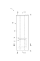
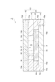
【解決手段】SERSユニット1は、表面増強ラマン散乱を生じさせる光学機能部3を有しているSERSチップ2と、内部空間Sを規定するとともに第一及び第二開口P1,P2が形成されており、第一開口P1を通して毛管力により液体試料Lを内部空間Sに導入する容器10と、を備えている。SERSチップ2は、光学機能部3が内部空間Sに露出しているように容器10に配置されている。容器10は、光学機能部3と対向し、かつ、光学機能部3に向かう励起光EL及び光学機能部3からの表面増強ラマン散乱光SLを透過させるカバー12を有している。
【選択図】図1
Description
d≦2Tcosθ/(hs・ρg)・・・(1)
F=2aΤcosθ・・・(2)
で表される。
W=adhρ・・・(3)
で表される。したがって、液柱に働く重力F’は、
F’=Wg=adhρg・・・(4)
となる。液柱が静止した状態では、液体が引き上げられる力Fと液柱に働く重力F’とが釣り合っているので、上記式(2)及び上記式(4)より、
2aΤcosθ=adhρg・・・(5)
となる。上記式(5)から、液面の高さhは、
h=2Τcosθ/(dρg)・・・(6)
となる。
h=1.45×10⁻⁵/d[m]・・・(7)
となる。したがって、例えば、間隔dを1[mm]とすると、液面の高さhは、14.5[mm]となる。なお、平行平板の毛管現象については、日本非破壊検査協会の機関誌VOL.55、NO1により詳しく記載されている。
hs≦h=2Tcosθ/(dρg)・・・(8)
となる。これにより、下記式(9)が導き出される。
d≦2Tcosθ/(hs・ρg)・・・(9)
Claims (6)
- 表面増強ラマン散乱を生じさせる光学機能部を有している表面増強ラマン散乱素子と、
内部空間を規定するとともに第一及び第二開口が形成されており、前記第一開口を通して毛管力により液体試料を前記内部空間に導入する容器と、を備え、
前記表面増強ラマン散乱素子は、前記光学機能部が前記内部空間に露出しているように前記容器に配置され、
前記容器は、前記光学機能部と対向し、かつ、前記光学機能部に向かう励起光及び前記光学機能部からの表面増強ラマン散乱光を透過させる光透過部を有している、
表面増強ラマン散乱ユニット。 - 前記表面増強ラマン散乱素子は、液体試料が毛管力により前記内部空間に導入される位置よりも前記第一開口側に前記光学機能部が位置するように前記容器に配置されている、請求項1に記載の表面増強ラマン散乱ユニット。
- 前記容器は、
前記表面増強ラマン散乱素子が配置されるとともに、前記光学機能部が露出する第一面を有している第一部材と、
前記光透過部が設けられているとともに、前記第一面に対向する第二面を有している第二部材と、を有し、
前記第一面と前記第二面とが前記内部空間を規定している、請求項1又は2に記載の表面増強ラマン散乱ユニット。 - 前記第一部材には、前記第一面より窪んだ第三面を有するとともに、前記表面増強ラマン散乱素子が収容される窪み部が設けられており、
前記表面増強ラマン散乱素子は、前記第三面に載置され、
前記窪み部の深さは、前記表面増強ラマン散乱素子の厚さと同等である、請求項3に記載の表面増強ラマン散乱ユニット。 - 前記第一面と前記第二面との間隔dと、前記第一開口と前記光学機能部との距離hsとは、前記第一及び第二面と液体試料との接触角をθ(θ<90°)、液体試料の表面張力をT、液体試料の密度をρ、及び重力加速度をgとして、下記式(1)を満足する、請求項3又は4に記載の表面増強ラマン散乱ユニット。
d≦2Tcosθ/(hs・ρg)・・・(1) - 前記容器は管状をなし、前記第一開口は前記容器の一端に形成されているとともに、前記第二開口は前記容器の他端に形成されている、請求項1〜5のいずれか一項記載の表面増強ラマン散乱ユニット。
Priority Applications (1)
| Application Number | Priority Date | Filing Date | Title |
|---|---|---|---|
| JP2015122905A JP6441174B2 (ja) | 2015-06-18 | 2015-06-18 | 表面増強ラマン散乱ユニット |
Applications Claiming Priority (1)
| Application Number | Priority Date | Filing Date | Title |
|---|---|---|---|
| JP2015122905A JP6441174B2 (ja) | 2015-06-18 | 2015-06-18 | 表面増強ラマン散乱ユニット |
Publications (2)
| Publication Number | Publication Date |
|---|---|
| JP2017009344A true JP2017009344A (ja) | 2017-01-12 |
| JP6441174B2 JP6441174B2 (ja) | 2018-12-19 |
Family
ID=57761499
Family Applications (1)
| Application Number | Title | Priority Date | Filing Date |
|---|---|---|---|
| JP2015122905A Expired - Fee Related JP6441174B2 (ja) | 2015-06-18 | 2015-06-18 | 表面増強ラマン散乱ユニット |
Country Status (1)
| Country | Link |
|---|---|
| JP (1) | JP6441174B2 (ja) |
Citations (10)
| Publication number | Priority date | Publication date | Assignee | Title |
|---|---|---|---|---|
| JPH03166957A (ja) * | 1989-11-27 | 1991-07-18 | Seiko Epson Corp | インクジェットヘッド |
| JPH1137922A (ja) * | 1997-03-26 | 1999-02-12 | Dainippon Printing Co Ltd | 光学的分析装置用測定チップ |
| US20060034729A1 (en) * | 2004-05-19 | 2006-02-16 | Vladimir Poponin | Optical sensor with layered plasmon structure for enhanced detection of chemical groups by SERS |
| JP2007506978A (ja) * | 2003-09-24 | 2007-03-22 | フォロニエ,ステファン,アンドレ | 流体サンプル中のターゲットを検出するデバイス、システムおよび方法 |
| JP2008051747A (ja) * | 2006-08-28 | 2008-03-06 | Jasco Corp | 液体試料測定方法 |
| US20090097022A1 (en) * | 2007-08-24 | 2009-04-16 | Dynamic Throughput Inc. | Discovery tool with integrated microfluidic biomarker optical detection array device and methods for use |
| JP2011511933A (ja) * | 2008-01-07 | 2011-04-14 | ダイナミック スループット インコーポレイテッド | 一体型マイクロ流体バイオマーカー光学検出アレイデバイスを用いた発見ツールおよび使用方法 |
| JP2014196981A (ja) * | 2013-03-29 | 2014-10-16 | 浜松ホトニクス株式会社 | 表面増強ラマン散乱ユニット、及びラマン分光分析方法 |
| US20140327913A1 (en) * | 2011-10-12 | 2014-11-06 | Brown University | Systems and methods enabling high-throughput, real time detection of analytes |
| JP2015096829A (ja) * | 2013-11-15 | 2015-05-21 | 富士フイルム株式会社 | ラマン分光装置 |
-
2015
- 2015-06-18 JP JP2015122905A patent/JP6441174B2/ja not_active Expired - Fee Related
Patent Citations (14)
| Publication number | Priority date | Publication date | Assignee | Title |
|---|---|---|---|---|
| JPH03166957A (ja) * | 1989-11-27 | 1991-07-18 | Seiko Epson Corp | インクジェットヘッド |
| JPH1137922A (ja) * | 1997-03-26 | 1999-02-12 | Dainippon Printing Co Ltd | 光学的分析装置用測定チップ |
| US6104484A (en) * | 1997-03-26 | 2000-08-15 | Dai Nippon Printing Co., Ltd. | Measuring chip for optical analyzer |
| US20070141722A1 (en) * | 2003-09-24 | 2007-06-21 | Follonier Stephane A | Device, system and method of detecting targets in a fluid sample |
| JP2007506978A (ja) * | 2003-09-24 | 2007-03-22 | フォロニエ,ステファン,アンドレ | 流体サンプル中のターゲットを検出するデバイス、システムおよび方法 |
| JP2007538264A (ja) * | 2004-05-19 | 2007-12-27 | ブィピー ホールディング、エルエルシー | Sersによる化学基の増強検出のための層状プラズモン構造をもつ光センサ |
| US20060034729A1 (en) * | 2004-05-19 | 2006-02-16 | Vladimir Poponin | Optical sensor with layered plasmon structure for enhanced detection of chemical groups by SERS |
| JP2008051747A (ja) * | 2006-08-28 | 2008-03-06 | Jasco Corp | 液体試料測定方法 |
| US20090097022A1 (en) * | 2007-08-24 | 2009-04-16 | Dynamic Throughput Inc. | Discovery tool with integrated microfluidic biomarker optical detection array device and methods for use |
| JP2011511933A (ja) * | 2008-01-07 | 2011-04-14 | ダイナミック スループット インコーポレイテッド | 一体型マイクロ流体バイオマーカー光学検出アレイデバイスを用いた発見ツールおよび使用方法 |
| US20140327913A1 (en) * | 2011-10-12 | 2014-11-06 | Brown University | Systems and methods enabling high-throughput, real time detection of analytes |
| JP2014196981A (ja) * | 2013-03-29 | 2014-10-16 | 浜松ホトニクス株式会社 | 表面増強ラマン散乱ユニット、及びラマン分光分析方法 |
| US20160061737A1 (en) * | 2013-03-29 | 2016-03-03 | Hamamatsu Photonics K.K. | Surface-enhanced raman scattering unit and raman spectroscopic analysis method |
| JP2015096829A (ja) * | 2013-11-15 | 2015-05-21 | 富士フイルム株式会社 | ラマン分光装置 |
Also Published As
| Publication number | Publication date |
|---|---|
| JP6441174B2 (ja) | 2018-12-19 |
Similar Documents
| Publication | Publication Date | Title |
|---|---|---|
| Wu et al. | Beat frequency quartz-enhanced photoacoustic spectroscopy for fast and calibration-free continuous trace-gas monitoring | |
| US6912049B2 (en) | Electromagnetic radiation attenuating and scattering member with improved thermal stability | |
| US10627339B2 (en) | Modular photoacoustic detection device | |
| CN103499391B (zh) | 光谱测量系统 | |
| JP6230250B2 (ja) | 表面増強ラマン散乱ユニット、及びラマン分光分析方法 | |
| CN106225926A (zh) | 一种小型化激光拉曼光谱仪 | |
| US11774347B2 (en) | Photoacoustic detecting device comprising a protective membrane | |
| JP4866364B2 (ja) | マイクロメートルサイズ深さフローチャンバ内のセンサを自己参照するためのシステム及び方法 | |
| KR102372083B1 (ko) | 생체 센서 및 이를 포함하는 생체 분석 시스템 | |
| Graciani et al. | 3D stochastic interferometer detects picometer deformations and minute dielectric fluctuations of its optical volume | |
| US8198592B2 (en) | Measuring instrument and measuring method | |
| Min et al. | On-chip near-infrared multi-gas sensing using chalcogenide anti-resonant hollow-core waveguides | |
| US8599373B1 (en) | Microcavity Raman sensor and method of use | |
| US20180231459A1 (en) | Lab-on-chip near-infrared spectrometer for label-free molecular analysis of a sample | |
| JP6441174B2 (ja) | 表面増強ラマン散乱ユニット | |
| JP6441172B2 (ja) | 表面増強ラマン散乱ユニット | |
| WO2019009209A1 (ja) | 光測定装置、導光部材及び光測定方法 | |
| CN105334571A (zh) | 使光入射到光波导中的入射方法 | |
| JP2020085615A (ja) | 光学測定器 | |
| JP2015078904A (ja) | 光学素子、分析装置、及び電子機器 | |
| JP2006125919A (ja) | 分光分析装置及び分光分析方法 | |
| CN106471354A (zh) | 生物体成分信息测定装置 | |
| JP2020034501A (ja) | 分光装置 | |
| JP2008116314A (ja) | 微少量液体測定装置 | |
| JP2016142617A (ja) | 電場増強素子、分析装置、及び電子機器 |
Legal Events
| Date | Code | Title | Description |
|---|---|---|---|
| A621 | Written request for application examination |
Free format text: JAPANESE INTERMEDIATE CODE: A621 Effective date: 20180205 |
|
| A977 | Report on retrieval |
Free format text: JAPANESE INTERMEDIATE CODE: A971007 Effective date: 20181012 |
|
| TRDD | Decision of grant or rejection written | ||
| A01 | Written decision to grant a patent or to grant a registration (utility model) |
Free format text: JAPANESE INTERMEDIATE CODE: A01 Effective date: 20181113 |
|
| A61 | First payment of annual fees (during grant procedure) |
Free format text: JAPANESE INTERMEDIATE CODE: A61 Effective date: 20181121 |
|
| R150 | Certificate of patent or registration of utility model |
Ref document number: 6441174 Country of ref document: JP Free format text: JAPANESE INTERMEDIATE CODE: R150 |
|
| LAPS | Cancellation because of no payment of annual fees |