JP2017010876A - Front combination lamp for vehicles - Google Patents
Front combination lamp for vehicles Download PDFInfo
- Publication number
- JP2017010876A JP2017010876A JP2015127701A JP2015127701A JP2017010876A JP 2017010876 A JP2017010876 A JP 2017010876A JP 2015127701 A JP2015127701 A JP 2015127701A JP 2015127701 A JP2015127701 A JP 2015127701A JP 2017010876 A JP2017010876 A JP 2017010876A
- Authority
- JP
- Japan
- Prior art keywords
- light
- lamp
- guide rod
- unit
- light reflecting
- Prior art date
- Legal status (The legal status is an assumption and is not a legal conclusion. Google has not performed a legal analysis and makes no representation as to the accuracy of the status listed.)
- Pending
Links
Images



Landscapes
- Non-Portable Lighting Devices Or Systems Thereof (AREA)
Abstract
【課題】光源からの出射光を遮ることなく且つ外光(太陽光)を効率よく遮光することにより、灯具ユニット(特に、DRLユニット)の点灯時と非点灯時とのコントラスを高めた車両用フロントコンビネーションランプを提供することにある。【解決手段】太陽光の影響を抑制するために、車両用コンビネーションランプの最前部にDRLユニット20を配置し、該コンビネーションランプを車両に搭載した時に車両側のバンパー60が太陽光を遮ってDRLユニット20に届かないような構成にした。また、DRLユニット20の前方からの外光の影響を抑制するために、エクステンション50に非反射処理を施し、アウターレンズ3、インナーレンズ40及びリフレクタ30の鏡面反射面31a、33aを介してエクステンション50に至った、DRLユニット20の前方からの外光がエクステンション50で反射されないようにした。【選択図】図9An object of the present invention is to improve the contrast between lighting and non-lighting of a lamp unit (particularly, a DRL unit) by efficiently blocking outside light (sunlight) without blocking light emitted from a light source. It is to provide a front combination lamp. In order to suppress the influence of sunlight, a DRL unit 20 is arranged at the forefront of a combination lamp for a vehicle, and when the combination lamp is mounted on a vehicle, a bumper 60 on the vehicle side blocks the sunlight and the DRL The configuration is such that it does not reach the unit 20. Further, in order to suppress the influence of external light from the front of the DRL unit 20, the extension 50 is subjected to a non-reflective treatment, and the extension 50 is passed through the outer lens 3, the inner lens 40, and the specular reflection surfaces 31a and 33a of the reflector 30. The external light from the front of the DRL unit 20 that has reached the position is prevented from being reflected by the extension 50. [Selection] Figure 9
Description
本発明は、車両用フロントコンビネーションランプに関するものであり、詳しくは、夫々が異なる機能を有する複数のランプユニットが一つの灯室内に一体的に組み込まれてなる車両用フロントコンビネーションランプに関する。 The present invention relates to a vehicle front combination lamp, and more particularly to a vehicle front combination lamp in which a plurality of lamp units each having a different function are integrally incorporated in one lamp chamber.
従来、この種のコンビネーションランプとしては、特許文献1に「車両用灯具」の名称で開示されたものがある。
Conventionally, this type of combination lamp is disclosed in
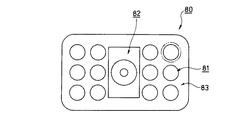
開示された車両用灯具80は図10にあるように、すれ違い配光を受け持つ複数のロービーム用灯具ユニット81と、走行配光を受け持つハイビーム用灯具ユニット82とがアウターレンズ83で覆われた構成を有している。
As shown in FIG. 10, the disclosed
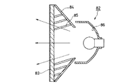
そのうち、ハイビーム用灯具ユニット82は図11にあるように、エクステンション84とアウターレンズ83との間にルーバー85が設けられており、該ルーバー85によって外光(特に、太陽光)の入射を遮光することにより、ハイビーム用灯具ユニット82の反射面86で反射した外光が、該ハイビーム用灯具ユニット82をロービーム用灯具ユニット81に対して目立たせることを抑制している。
Among them, the high
ところで、上記ハイビーム用灯具ユニット82を構成するルーバー86は、外光の遮光に対しては有効に機能するが、同時に、光源からの出射光を部分的に遮ることになり、光の利用効率がよくない。
By the way, the
そこで、本発明は上記問題に鑑みて創案なされたもので、その目的とするところは、光源からの出射光を遮ることなく且つ外光(太陽光)を効率よく遮光することにより、灯具ユニット(特に、DRLユニット)の点灯時と非点灯時とのコントラスを高めた車両用フロントコンビネーションランプを提供することにある。 Therefore, the present invention was devised in view of the above-mentioned problems, and the object of the present invention is to provide a lamp unit (not shown) by efficiently blocking outside light (sunlight) without blocking light emitted from the light source. In particular, an object of the present invention is to provide a front combination lamp for a vehicle in which the contrast between the lighting and non-lighting of the DRL unit is increased.
上記課題を解決するために、本発明の請求項1に記載された発明は、灯室内に複数のランプユニットを収容してなる車両用フロントコンビネーションランプであって、前記複数のランプユニットのうち少なくとも1つがDRLユニットであり、前記DRLユニットは、光源と、光源からの出射光を前方方向に反射する光反射面を有するリフレクタと、前記リフレクタの前側周囲に位置して前記灯室内の不要な部分を遮蔽するエクステンションとを備え、前記DRLユニットは、前記車両用フロントコンビネーションランプの最前部に位置して該車両用フロントコンビネーションランプを車両に搭載したときに車両側のバンパーによって太陽光が遮られることにより、前記光反射面への太陽光の映り込みを防止することを特徴とするものである。
In order to solve the above-described problem, the invention described in
また、本発明の請求項2に記載された発明は、請求項1において、前記エクステンションは前記リフレクタ側の面を非光反射面とし、前記DRLユニットの前方から該DRLユニットに向けて照射されて前記リフレクタの光反射面を介して前記エクステンションの非光反射面に届いた外光が、該非光反射面によって前記光反射面への映り込みを防止されることを特徴とするものである。
Also, in the invention described in
また、本発明の請求項3に記載された発明は、請求項1又は請求項2のいずれかにおいて、前記DRLランプの後上側にポジショニングランプユニットが位置しており、前記ポジショニングランプユニットは、光源と、導光棒と、前記導光棒の下方から該導光棒に沿って前方に延びる平板状の光反射部材と、前記導光棒の上方から該導光棒に沿って前方に、前記光反射部材と対峙するように板状に延びるインナーレンズとを備え、前記光源から出射して前記導光棒に入射した光が該導光棒内を導光され、前記導光棒から前記インナーレンズに向けて出射した光は該インナーレンズを通してポジショニングランプユニット外に出射し、前記導光棒から前記光反射部材に向けて出射した光は該光反射部材で反射されて反射光が前記インナーレンズを通してポジショニングランプユニット外に出射されることを特徴とするものである。 According to a third aspect of the present invention, in any one of the first or second aspect, a positioning lamp unit is located on the rear upper side of the DRL lamp, and the positioning lamp unit is a light source. A light guide rod, a flat plate-like light reflecting member extending forward along the light guide rod from below the light guide rod, and forward along the light guide rod from above the light guide rod, An inner lens extending in a plate shape so as to face the light reflecting member, and light emitted from the light source and incident on the light guide rod is guided through the light guide rod, and the inner light is transmitted from the light guide rod. The light emitted toward the lens is emitted outside the positioning lamp unit through the inner lens, and the light emitted from the light guide rod toward the light reflecting member is reflected by the light reflecting member, and the reflected light is reflected on the inner lens. Is characterized in that the emitted outside positioning the lamp unit through.
本発明によれば、光源と、光源からの出射光を車両前方側に向けて反射する鏡面反射面を有するリフレクタと、リフレクタの前側に位置してリフレクタによる反射光をそのまま車両前方側に向けて透過するインナーレンズとを備えたDRLユニットにおいて、DRLユニットを車両用フロントコンビネーションランプの灯室内の最前部に配置し、インナーレンズを囲むように周囲に配置されたエクステンションを非反射性を有するものとした。 According to the present invention, the light source, the reflector having the specular reflection surface that reflects the light emitted from the light source toward the front side of the vehicle, and the light reflected by the reflector that is positioned on the front side of the reflector are directed directly toward the front side of the vehicle. In a DRL unit having a transparent inner lens, the DRL unit is disposed in the foremost part in the lamp chamber of the vehicle front combination lamp, and the extension disposed around the inner lens is non-reflective. did.
これにより、車両用フロントコンビネーションランプコンビネーションランプを車両に搭載した時に車両側のバンパーが太陽光を遮ってリフレクタの鏡面反射面に届くことはない。また、前方からリフレクタの鏡面反射面を経てエクステンションに到達した光が該エクステンションで反射されることがない。 Thereby, when the vehicle front combination lamp combination lamp is mounted on the vehicle, the bumper on the vehicle side does not block sunlight and reach the specular reflection surface of the reflector. Further, the light that reaches the extension from the front through the specular reflection surface of the reflector is not reflected by the extension.
そのため、リフレクタの鏡面反射面への太陽光や外光の映り込みが防止され、DRLユニットから出射された、点灯時と非点灯時のコントラストが良好な鮮明な光によって、昼間走行においても歩行者や対向車両等からの良好な被視認性を確保することができる。 Therefore, the reflection of sunlight and external light on the mirror reflection surface of the reflector is prevented, and pedestrians can also be used during daytime driving due to clear light emitted from the DRL unit and having good contrast between lighting and non-lighting. And good visibility from an oncoming vehicle or the like can be ensured.
以下、この発明の好適な実施形態を図1〜図9を参照しながら、詳細に説明する(同一部分については同じ符号を付す)。尚、以下に述べる実施形態は、本発明の好適な具体例であるから、技術的に好ましい種々の限定が付されているが、本発明の範囲は、以下の説明において特に本発明を限定する旨の記載がない限り、これらの実施形態に限られるものではない。 Hereinafter, preferred embodiments of the present invention will be described in detail with reference to FIGS. 1 to 9 (the same reference numerals are given to the same portions). The embodiments described below are preferable specific examples of the present invention, and thus various technically preferable limitations are given. However, the scope of the present invention particularly limits the present invention in the following description. Unless stated to the effect, the present invention is not limited to these embodiments.
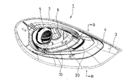
図1は本発明に係る実施形態の車両用フロントコンビネーションランプ(以下、「コンビネーションランプ」と略称する)の斜視説明図、図2は図1のA−A断面説明図、図3は図1のB−B断面説明図である。 FIG. 1 is a perspective explanatory view of a vehicle front combination lamp (hereinafter abbreviated as “combination lamp”) according to an embodiment of the present invention, FIG. 2 is an AA cross-sectional explanatory view of FIG. 1, and FIG. It is BB cross-section explanatory drawing.
実施形態のコンビネーションランプ1は、車両に搭載した状態において、車両の後側から前側に向かって上側から下側に傾斜(スラント)した形状を呈しており、ハウジング2とアウターレンズ3とで形成された灯室4内の、外側にすれ違いビーム用配光パターンを形成するプロジェクタ型のすれ違いビーム用ランプユニット5が位置し、その内側に走行ビーム用配光パターンを形成するリフレクタ型の走行ビーム用ランプユニット6が位置している。
The
また、すれ違いビーム用ランプユニット5及び走行ビーム用ランプユニット6の前下側にポジショニングランプユニット10が位置し、更にその前下側にDRL(デイタイムランニングランプ)ユニット20が位置している。
Further, a
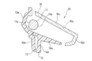
そのうち、ポジショニングランプユニット10は、図2に示す構成からなっている。
Among them, the
具体的には、光源(図示せず)と、光源からの出射光を導光する導光棒11と、導光棒11からの出射光を反射する第1光反射部材13及び第2光反射部材14と、第2光反射部材14の上方に位置して該第2光反射部材14による反射光を車両前方に向けて拡散制御するインナーレンズ16とを備えている。
Specifically, a light source (not shown), a
光源は、半導体発光装置(例えば、LED)からなり、導光棒11の一方の端面近傍又は両端面近傍に配置されている。
The light source is composed of a semiconductor light emitting device (for example, LED), and is disposed in the vicinity of one end surface of the
導光棒11は、前側に凸状に湾曲して左右に延びる形状を有しており、外周面の一部に設けられた内部反射面(全反射面)が湾曲状の内側を延長方向に沿って延びる光反射部11aを有しており、光反射部11aの反対側は、湾曲状の外側を延長方向に沿って延びる光出射反射部11bとなっている。導光棒11の光反射部11aは具体的には、例えば、導光棒11の延長方向に垂直に延びる三角凹凸11cが該延長方向に連続して並設されてなる内部反射面からなっている(図4(導光棒の部分斜視説明図)参照)。
The
但し、光反射部11aは上記形状に限られるものではなく、求められる光学仕様に基づいて適宜設定される。例えば、図5(導光棒の部分斜視説明図)にあるように、光反射部11aを平坦面で構成してもよい。
However, the
図2に戻って、第1光反射部材13及び第2光反射部材14の夫々は、光反射率の高い白色樹脂で形成されており、そのうち、第1光反射部材13は、導光棒11の光反射部11aの後方に該光反射部11aに沿って湾曲状に位置する湾曲光反射部13aと、湾曲光反射部13aの下端部から該下端部に沿って下方に延びる延長部13bを有しており、一方、第2光反射部材14は、導光棒11の下方から該導光棒11に沿って前方に板状に延びる板状光反射部14aと、導光棒11の下方から該導光棒11に沿って下方に延びる延長部14bを有している。
Returning to FIG. 2, each of the first
インナーレンズ16は、導光棒11の上方から該導光棒11に沿って前方に、第2光反射部材14の板状光反射部14aと対峙するように板状に延びる板状光出射部16aと、板状光出射部16aの先端部から該先端部に沿って折り曲げられて下方の、第2光反射部材14の板状光反射部14aの近傍まで延びる折曲状の折曲状光出射部16bを有している。
The
板状光出射部16a及び折曲状光出射部16bを有するインナーレンズ16は、両面又はいずれか一方の面に光の拡散制御手段(例えば、シボ加工)16cが施されている。
The
したがって、導光棒11は、第1光反射部材13の湾曲光反射部13aと、第2光反射部材14の板状光反射部14aと、板状光出射部16a及び折曲状光出射部16bを有するインナーレンズ16とによって区画された空間内に収容されている。
Therefore, the
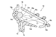
そこで(図6(光路説明図)参照)、導光棒11の一方の端面近傍又は両端面近傍に配置された光源から出射されて導光棒11内に入射した光は、光反射部11aと光出射反射部11bとの間で内部反射(全反射)を繰り返しながら他端面側に向かって導光される途中で、光反射部11aで内部反射された反射光の一部が光出射反射部11bから出射される。
Therefore (see FIG. 6 (optical path explanatory diagram)), the light emitted from the light source disposed in the vicinity of one end face or both end faces of the
導光棒11の光出射反射部11bから出射された光は、一部がインナーレンズ16の折曲状光出射部16bに向かい、一部がインナーレンズ16の板状光出射面16aに向かい、一部が第2光反射部材14の板状光反射部14aに向かう。
The light emitted from the light emitting / reflecting
そのうち、導光棒11の光出射反射部11bからインナーレンズ16の折曲状光出射部16bに向けて出射された光L1は、折曲状光出射部16bに施された拡散制御手段16cによって適宜な拡散光となって前方に向けて出射される。
Among them, the light L1 emitted from the light emitting / reflecting
また、導光棒11の光出射反射部11bからインナーレンズ16の板状光出射部16aに向けて出射された光L2は、折曲状光出射部16bと同様に板状光出射部16aに施された拡散制御手段16cによって適宜な拡散光となって前方に向けて出射される。
The light L2 emitted from the light emitting / reflecting
更に、導光棒11の光出射反射部11bから第2光反射部材14の板状光反射部14aに向けて出射された光L3は、板状光反射部14aで反射されて反射光が該板状光反射部14aに対峙する、インナーレンズ16の板状光出射部16aに向かい、板状光出射部16aに施された拡散制御手段16cによって適宜な拡散光となって前方に向けて出射される。
Further, the light L3 emitted from the light emitting / reflecting
また、導光棒11内を導光中に光反射部11aに至った光は、光反射部11aで内部反射して導光棒11内に戻る光と、光反射部11aから出射される光とが存在する。この場合、光反射部11aから出射される光L4は、該光反射部11aに対向する、第1光反射部材13の湾曲光反射部13aで反射されて再度光反射部11aから導光棒11内に入射し、導光棒11内を導光されて光出射反射面11bから出射される。
In addition, the light that reaches the
したがって、光源から出射して導光棒11内に入射した光は、光出射反射面11bから効率よく出射されてその多くがインナーレンズ16からの出射光として寄与するものとなる。その結果、上記構成のポジショニングランプユニット10は、光源から出射した光の利用効率の高い、明るいランプユニットとなる。
Therefore, the light emitted from the light source and entering the
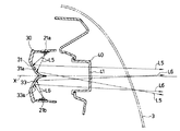
また、DRLユニット20は、図3に示す構成からなっている。
The
具体的には、光源21と、光源21を実装すると同時に光源21からの出射光を反射して反射光を車両前方方向の所定方向に配光制御するリフレクタ30と、リフレクタ30の前側に位置してリフレクタ30による反射光をそのまま車両前方方向に出射するインナーレンズ40と、インナーレンズ40を囲むように周囲に配置されたエクステンション50を備えている。
Specifically, the
光源21は、半導体発光装置(例えば、LED)からなり、基板22に実装されている。
The
リフレクタ30は、夫々が後側に凸の2つの湾曲部31、33が上下に連続して繋がると共に、上側の湾曲部31の上縁から前側に延びる延長部32及び下側の湾曲部33の下縁から前側に延びる延長部34を有する断面が、前側に凸状に湾曲して延びる形状を有している。
The
インナーレンズ40は、上下に延びる素通しの透光部41と透光部41の上縁から後側に延びる脚部42及び透光部41の下縁から後側に延びる脚部43を有する断面が、前側に凸状に湾曲して延びる形状を有している。
The
エクステンション50は、少なくとも裏面(リフレクタ30側の面)50aを非光反射面としている。この非光反射面はエクステンション50自体を非反射性を有する黒色樹脂で形成するか、あるいは裏面50aに黒色塗装等による非反射処理を施しており、インナーレンズ40の周囲を囲むように略上下方向及び略左右方向に延在している。
The
リフレクタ30の湾曲部31、33の夫々の内面(インナーレンズ40に対向する側の面)31a、33aはアルミ蒸着等による鏡面反射面からなり、湾曲部31の内面31aは湾曲部31の上縁から延びる延長部32に実装された光源21aの位置を焦点位置とする放物面に近似した面からなっており、同様に、湾曲部33の内面33aは湾曲部33の上縁から延びる延長部34に実装された光源21bの位置を焦点位置とする放物面に近似した面からなっている。
Inner surfaces (surfaces facing the inner lens 40) 31a and 33a of the
そこで(図7(光路説明図)参照)、光源21aからリフレクタ30の湾曲部31の内面31aに向けて出射された光L5は、内面31aの近似放物反射面で、フレクタ30の2つの湾曲部31、33が繋がる部分を通り水平面に沿って前方に延びる中心軸Xに対して、下方に向けて反射されてインナーレンズ40の透光部41に向かい、光源21bからリフレクタ30の湾曲部33の内面33aに向けて出射された光L6は、内面33aの近似放物反射面で、中心軸Xに対して上方から下方の範囲に反射されてインナーレンズ40の透光部41に向かう。
Accordingly (see FIG. 7 (optical path explanatory diagram)), the light L5 emitted from the
インナーレンズ40の透光部41に到達した光L5、L6は、素通しの透光部41をそのまま透過して適宜な配光特性を有する光として前方に向けて出射される。
The lights L5 and L6 that have reached the
ところで、上記構成のDRLユニット20は、昼間走行中の車両の被視認性を高めるために周囲が明るい中で点灯させるものである。そのため、夜間走行時にはない外光の影響を受けることがある。
By the way, the
具体的には、太陽の直射光がアウターレンズ3及びインナーレンズ40を通してリフレクタ30の湾曲部31、33の夫々の内面(鏡面反射面)31a、33aに届き、鏡面反射面31a、33aで反射された光がインナーレンズ40を及びアウターレンズ3を通して前方に照射される。したがって、DRLユニット20を前方から見ると、観視者には、リフレクタ30の鏡面反射面31a、33aに映り込んだ太陽光がインナーレンズ40及びアウターレンズ3を通して観視される。
Specifically, the direct sunlight reaches the inner surfaces (specular reflection surfaces) 31a and 33a of the
また、前方からDRLユニット20に照射された光(外光)は、アウターレンズ3及びインナーレンズ40を通してリフレクタ30の鏡面反射面31a、33aに至り、鏡面反射面31a、33aで反射されてエクステンション50に届く。このとき、エクステンション50が一般的な鏡面反射面を有している場合、エクステンション50で反射された光が、鏡面反射面31a、33a、インナーレンズ40及びアウターレンズ3による逆の光路を辿って前方に照射される。
Further, light (external light) irradiated on the
したがって、DRLユニット20を前方から見ると、観視者には、エクステンション50で反射してリフレクタ30の鏡面反射面31a、33aに映り込んだ前方からの光がインナーレンズ40及びアウターレンズ3を通して観視される。
Therefore, when the
そこで、前方からDRLユニット20を見ると観視者には、DRLユニット20の光源からの光、リフレクタ30の鏡面反射面31a、33aに映し込まれた太陽光、及び同様にリフレクタ30の鏡面反射面31a、33aに映し込まれた前方からの外光が重畳されて観視される。
Therefore, when the
そのため、DRLユニット20を前方から見た時に、DRLユニット20本来の出射光が外光によってマスキングされて点灯時と非点灯時のコントラストが悪いものとなってしまう。
Therefore, when the
本発明は、DRLユニット20の点灯時と非点灯時の良好なコントラストを得るための施策を施している。
The present invention takes measures to obtain a good contrast when the
まず、太陽光の影響を抑制するために、図8(ランプユニットの配置説明図)にあるように、コンビネーションランプ1の灯室4内に収容するランプユニットの配置位置を、すれ違いビーム用ランプユニット5と走行ビーム用ランプユニット6を後部側に配置し、その前下側にポジショニングランプユニット10が位置し、更にその前下側(最前部)にDRLユニット20を配置した。
First, in order to suppress the influence of sunlight, as shown in FIG. 8 (description of arrangement of the lamp unit), the arrangement position of the lamp unit accommodated in the lamp chamber 4 of the
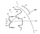
そのため、図9(太陽光・外光に対する説明図)にあるように、コンビネーションランプ1を車両に搭載した時に車両側のバンパー60が太陽光を遮ってコンビネーションランプ(特に、リフレクタ30の湾曲部31、33の夫々の鏡面反射面31a、33a)に届かないような構成にしている。
Therefore, as shown in FIG. 9 (an explanatory diagram for sunlight / external light), when the
また、DRLユニット20の前方からの外光の影響を抑制するために、エクステンション50の裏面50aを非光反射面とし、アウターレンズ3、インナーレンズ40及びリフレクタ30の湾曲部31、33の夫々の鏡面反射面31a、33aを介してエクステンション50の裏面50aに至った、DRLユニット20の前方からの外光がエクステンション50で反射されないようにしている。
In order to suppress the influence of external light from the front of the
これにより、リフレクタ30の湾曲部31、33の夫々の鏡面反射面31a、33aへの太陽光や外光の映り込みが防止され、DRLユニット20から出射された鮮明な光によって、昼間走行においても歩行者や対向車両等からの良好な被視認性を確保することができる。
Thereby, the reflection of sunlight and external light on the respective specular reflection surfaces 31a and 33a of the
1… フロントコンビネーションランプ
2… ハウジング
3… アウターレンズ
4… 灯室
5… すれ違いビーム用ランプユニット
6… 走行ビーム用ランプユニット
10… ポジショニングランプユニット
11… 導光棒
11a… 光反射部
11b… 光出射反射部
11c… 三角凹凸
13… 第1光反射部材
13a… 湾曲光反射部
13b… 延長部
14… 第2光反射部材
14a… 板状光反射部
14b… 延長部
16… インナーレンズ
16a… 板状光出射部
16b… 折曲状光出射部
16c… 拡散制御手段
20… DRLユニット
21… 光源
21a… 光源
21b… 光源
22… 基板
30… リフレクタ
31… 湾曲部
31a… 内面
32… 延長部
33… 湾曲部
33a… 内面
34… 延長部
40… インナーレンズ
41… 透光部
42… 脚部
43… 脚部
50… エクステンション
60… バンパー
DESCRIPTION OF
60 ... Bumper
Claims (3)
前記複数のランプユニットのうち少なくとも1つがDRLユニットであり、
前記DRLユニットは、光源と、光源からの出射光を前方方向に反射する光反射面を有するリフレクタと、前記リフレクタの前側周囲に位置して前記灯室内の不要な部分を遮蔽するエクステンションとを備え、
前記DRLユニットは、前記車両用フロントコンビネーションランプの最前部に位置して該車両用フロントコンビネーションランプを車両に搭載したときに車両側のバンパーによって太陽光が遮られることにより、前記光反射面への太陽光の映り込みを防止することを特徴とする車両用フロントコンビネーションランプ。 A vehicle front combination lamp in which a plurality of lamp units are accommodated in a lamp chamber,
At least one of the plurality of lamp units is a DRL unit,
The DRL unit includes a light source, a reflector having a light reflecting surface that reflects light emitted from the light source in a forward direction, and an extension that is positioned around the front side of the reflector and shields unnecessary portions in the lamp chamber. ,
The DRL unit is positioned at the forefront of the vehicle front combination lamp, and when the vehicle front combination lamp is mounted on the vehicle, sunlight is blocked by a vehicle-side bumper, so that the light reflecting surface A front combination lamp for vehicles that prevents the reflection of sunlight.
前記ポジショニングランプユニットは、光源と、導光棒と、前記導光棒の下方から該導光棒に沿って前方に延びる平板状の光反射部材と、前記導光棒の上方から該導光棒に沿って前方に、前記光反射部材と対峙するように板状に延びるインナーレンズとを備え、
前記光源から出射して前記導光棒に入射した光が該導光棒内を導光され、前記導光棒から前記インナーレンズに向けて出射した光は該インナーレンズを通してポジショニングランプユニット外に出射し、前記導光棒から前記光反射部材に向けて出射した光は該光反射部材で反射されて反射光が前記インナーレンズを通してポジショニングランプユニット外に出射されることを特徴とする請求項1又は請求項2のいずれかに記載の車両用フロントコンビネーションランプ。 A positioning lamp unit is located on the upper rear side of the DRL lamp;
The positioning lamp unit includes a light source, a light guide rod, a flat light reflecting member extending forward along the light guide rod from below the light guide rod, and the light guide rod from above the light guide rod. And an inner lens extending in a plate shape so as to face the light reflecting member,
Light emitted from the light source and incident on the light guide rod is guided through the light guide rod, and light emitted from the light guide rod toward the inner lens is emitted outside the positioning lamp unit through the inner lens. The light emitted from the light guide rod toward the light reflecting member is reflected by the light reflecting member, and the reflected light is emitted outside the positioning lamp unit through the inner lens. The vehicle front combination lamp according to claim 2.
Priority Applications (1)
| Application Number | Priority Date | Filing Date | Title |
|---|---|---|---|
| JP2015127701A JP2017010876A (en) | 2015-06-25 | 2015-06-25 | Front combination lamp for vehicles |
Applications Claiming Priority (1)
| Application Number | Priority Date | Filing Date | Title |
|---|---|---|---|
| JP2015127701A JP2017010876A (en) | 2015-06-25 | 2015-06-25 | Front combination lamp for vehicles |
Publications (1)
| Publication Number | Publication Date |
|---|---|
| JP2017010876A true JP2017010876A (en) | 2017-01-12 |
Family
ID=57761719
Family Applications (1)
| Application Number | Title | Priority Date | Filing Date |
|---|---|---|---|
| JP2015127701A Pending JP2017010876A (en) | 2015-06-25 | 2015-06-25 | Front combination lamp for vehicles |
Country Status (1)
| Country | Link |
|---|---|
| JP (1) | JP2017010876A (en) |
Cited By (1)
| Publication number | Priority date | Publication date | Assignee | Title |
|---|---|---|---|---|
| JP2022062368A (en) * | 2020-10-08 | 2022-04-20 | 三菱自動車工業株式会社 | Vehicular lighting fixture |
Citations (4)
| Publication number | Priority date | Publication date | Assignee | Title |
|---|---|---|---|---|
| JPH0191647U (en) * | 1987-12-10 | 1989-06-15 | ||
| JP2002367411A (en) * | 2001-06-05 | 2002-12-20 | Koito Mfg Co Ltd | Vehicle headlights |
| JP2013175334A (en) * | 2012-02-24 | 2013-09-05 | Stanley Electric Co Ltd | Vehicle lamp |
| JP2014059958A (en) * | 2012-09-14 | 2014-04-03 | Koito Mfg Co Ltd | Vehicle lamp fitting |
-
2015
- 2015-06-25 JP JP2015127701A patent/JP2017010876A/en active Pending
Patent Citations (4)
| Publication number | Priority date | Publication date | Assignee | Title |
|---|---|---|---|---|
| JPH0191647U (en) * | 1987-12-10 | 1989-06-15 | ||
| JP2002367411A (en) * | 2001-06-05 | 2002-12-20 | Koito Mfg Co Ltd | Vehicle headlights |
| JP2013175334A (en) * | 2012-02-24 | 2013-09-05 | Stanley Electric Co Ltd | Vehicle lamp |
| JP2014059958A (en) * | 2012-09-14 | 2014-04-03 | Koito Mfg Co Ltd | Vehicle lamp fitting |
Cited By (2)
| Publication number | Priority date | Publication date | Assignee | Title |
|---|---|---|---|---|
| JP2022062368A (en) * | 2020-10-08 | 2022-04-20 | 三菱自動車工業株式会社 | Vehicular lighting fixture |
| JP7539290B2 (en) | 2020-10-08 | 2024-08-23 | 三菱自動車工業株式会社 | Vehicle lighting fixtures |
Similar Documents
| Publication | Publication Date | Title |
|---|---|---|
| JP5800161B2 (en) | LED lamp module | |
| JP6029298B2 (en) | Vehicle lighting | |
| JP2013222553A (en) | Lamp fitting for vehicle | |
| CN101666454A (en) | Lighting device for vehicle | |
| JP2013016400A (en) | Vehicular headlight | |
| JP6609135B2 (en) | Rear combination lamp for vehicles | |
| WO2015156121A1 (en) | Vehicular light guide member and vehicular lighting equipment | |
| WO2016104111A1 (en) | Vehicular lighting tool | |
| JP2018098105A (en) | Vehicular headlamp | |
| US10612743B2 (en) | Vehicle lamp | |
| WO2019225645A1 (en) | Vehicle lamp | |
| JP2019050132A (en) | Vehicular lighting fixture | |
| JP2015230872A (en) | Vehicle lamp | |
| KR102435180B1 (en) | Lamp for vehicle | |
| KR102446505B1 (en) | car lamp | |
| KR101917209B1 (en) | Lamp for vehicle | |
| JP2019220411A (en) | Light guide device for vehicle and lighting appliance for vehicle | |
| JP6221438B2 (en) | Vehicle lighting | |
| JP2015130293A (en) | Vehicle lighting | |
| JP2018142457A (en) | Vehicular lighting fixture | |
| JP5773189B2 (en) | Lamp | |
| JP5457780B2 (en) | Vehicle lamp | |
| JP5910096B2 (en) | Vehicle lighting | |
| JP2014063641A (en) | Lighting fixture for vehicle | |
| JP2019139934A (en) | Lighting appliance for vehicle |
Legal Events
| Date | Code | Title | Description |
|---|---|---|---|
| A621 | Written request for application examination |
Free format text: JAPANESE INTERMEDIATE CODE: A621 Effective date: 20180524 |
|
| A977 | Report on retrieval |
Free format text: JAPANESE INTERMEDIATE CODE: A971007 Effective date: 20190322 |
|
| A131 | Notification of reasons for refusal |
Free format text: JAPANESE INTERMEDIATE CODE: A131 Effective date: 20190402 |
|
| A02 | Decision of refusal |
Free format text: JAPANESE INTERMEDIATE CODE: A02 Effective date: 20191008 |