JP2017013564A - Pneumatic tire, and method for manufacturing the same - Google Patents
Pneumatic tire, and method for manufacturing the same Download PDFInfo
- Publication number
- JP2017013564A JP2017013564A JP2015130185A JP2015130185A JP2017013564A JP 2017013564 A JP2017013564 A JP 2017013564A JP 2015130185 A JP2015130185 A JP 2015130185A JP 2015130185 A JP2015130185 A JP 2015130185A JP 2017013564 A JP2017013564 A JP 2017013564A
- Authority
- JP
- Japan
- Prior art keywords
- tire
- groove
- profile portion
- profile
- circumferential main
- Prior art date
- Legal status (The legal status is an assumption and is not a legal conclusion. Google has not performed a legal analysis and makes no representation as to the accuracy of the status listed.)
- Pending
Links
Images


Landscapes
- Tires In General (AREA)
- Tyre Moulding (AREA)
Abstract
Description
この発明は、空気入りタイヤおよびその製造方法に関し、さらに詳しくは、ベルト耐久性能を向上できる空気入りタイヤおよびその製造方法に関する。 The present invention relates to a pneumatic tire and a manufacturing method thereof, and more particularly to a pneumatic tire capable of improving belt durability and a manufacturing method thereof.
一般的な空気入りタイヤでは、タイヤの車両装着状態にて車幅方向外側に位置する最外周方向主溝の溝底に、グルーブクラックが発生するという課題がある。このグルーブクラックが成長してベルト層に至るとタイヤのベルト耐久性能が低下するため、好ましくない。 In a general pneumatic tire, there is a problem that a groove crack occurs at the groove bottom of the outermost circumferential main groove located on the outer side in the vehicle width direction when the tire is mounted on the vehicle. If this groove crack grows and reaches the belt layer, the belt durability performance of the tire is lowered, which is not preferable.
なお、本願とは異なる解決課題を有するものの、特徴的な断面形状をもつベルト層を備える従来の空気入りタイヤとして、特許文献1〜3に記載される技術が知られている。 In addition, although it has a solution subject different from this application, the technique described in patent documents 1-3 is known as a conventional pneumatic tire provided with the belt layer which has a characteristic cross-sectional shape.
この発明は、ベルト耐久性能を向上できる空気入りタイヤおよびその製造方法を提供することを目的とする。 An object of the present invention is to provide a pneumatic tire capable of improving belt durability and a method for manufacturing the same.
上記目的を達成するため、この発明にかかる空気入りタイヤは、カーカス層と、前記カーカス層の外周に配置された一対の交差ベルトと、前記一対の交差ベルトの外周に配置されたトレッドゴムと、タイヤ周方向に延在する複数の周方向主溝と、前記周方向主溝に区画されて成る複数の陸部とを備える空気入りタイヤであって、タイヤ径方向外側にある前記交差ベルトを外側交差ベルトとして定義し、タイヤ幅方向の最も外側にある前記周方向主溝を最外周方向主溝として定義するときに、タイヤ子午線方向の断面視にて、前記外側交差ベルトのプロファイルが、タイヤ内腔側に凸となる形状を有すると共に前記最外周方向主溝の溝下領域に位置する溝下プロファイル部と、タイヤ径方向外側に凸となる形状を有すると共に前記溝下プロファイル部のタイヤ幅方向内側端部に接続する第一プロファイル部と、タイヤ径方向外側に凸となる形状を有すると共に前記溝下プロファイル部のタイヤ幅方向外側端部に接続する第二プロファイル部とを備えることを特徴とする。 In order to achieve the above object, a pneumatic tire according to the present invention includes a carcass layer, a pair of cross belts disposed on an outer periphery of the carcass layer, a tread rubber disposed on an outer periphery of the pair of cross belts, A pneumatic tire comprising a plurality of circumferential main grooves extending in the tire circumferential direction and a plurality of land portions defined by the circumferential main grooves, wherein the intersecting belt on the outer side in the tire radial direction is outside When the outer circumferential belt is defined as a cross belt, and the circumferential main groove at the outermost side in the tire width direction is defined as the outermost circumferential main groove, the profile of the outer cross belt in the tire meridian direction is A groove-shaped profile portion that is convex toward the cavity side and is located in a groove-lower region of the outermost circumferential main groove; a groove-shaped profile portion that is convex outward in the tire radial direction; A first profile portion connected to the tire width direction inner end portion of the tire portion, a second profile portion having a shape protruding outward in the tire radial direction and connected to the tire width direction outer end portion of the lower groove profile portion, It is characterized by providing.
また、この発明にかかる空気入りタイヤの製造方法は、上記空気入りタイヤの製造方法であって、グリーンタイヤの成形工程にて、前記外側交差ベルトの前記最外周方向主溝に対応する位置に前記溝下プロファイル部を構成する凹みを形成するステップと、前記グリーンタイヤを加硫成形するステップとを備えることを特徴とする。 Further, the manufacturing method of the pneumatic tire according to the present invention is the manufacturing method of the pneumatic tire described above, in the green tire forming step, at the position corresponding to the outermost circumferential main groove of the outer cross belt. The method includes a step of forming a dent constituting the sub-groove profile portion, and a step of vulcanizing the green tire.
この発明にかかる空気入りタイヤでは、外側交差ベルトのプロファイルがタイヤ内腔側に凸となる溝下プロファイル部を最外周方向主溝の溝下領域に備えるので、最外周方向主溝の溝底から外側交差ベルトまでの溝底ゲージが増加する。これにより、グルーブクラックの成長に起因する外側交差ベルトの損傷が抑制されて、タイヤのベルト耐久性能が向上する利点がある。 In the pneumatic tire according to the present invention, the profile of the outer cross belt is provided with a lower groove profile portion that protrudes toward the tire lumen side in the lower groove region of the outermost circumferential main groove. Groove bottom gauge to outer cross belt increases. Thereby, the damage of the outer cross belt due to the growth of the groove crack is suppressed, and there is an advantage that the belt durability performance of the tire is improved.
以下、この発明につき図面を参照しつつ詳細に説明する。なお、この実施の形態によりこの発明が限定されるものではない。また、この実施の形態の構成要素には、発明の同一性を維持しつつ置換可能かつ置換自明なものが含まれる。また、この実施の形態に記載された複数の変形例は、当業者自明の範囲内にて任意に組み合わせが可能である。 Hereinafter, the present invention will be described in detail with reference to the drawings. Note that the present invention is not limited to the embodiments. Further, the constituent elements of this embodiment include those that can be replaced while maintaining the identity of the invention and that are obvious for replacement. In addition, a plurality of modifications described in this embodiment can be arbitrarily combined within a range obvious to those skilled in the art.
[空気入りタイヤ]
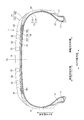
図1は、この発明の実施の形態にかかる空気入りタイヤを示すタイヤ子午線方向の断面図である。同図は、タイヤ径方向の片側領域の断面図を示している。また、同図は、空気入りタイヤの一例として、乗用車用ラジアルタイヤを示している。
[Pneumatic tire]
FIG. 1 is a sectional view in the tire meridian direction showing a pneumatic tire according to an embodiment of the present invention. This figure shows a cross-sectional view of one side region in the tire radial direction. The figure shows a radial tire for a passenger car as an example of a pneumatic tire.
同図において、タイヤ子午線方向の断面とは、タイヤ回転軸(図示省略)を含む平面でタイヤを切断したときの断面をいう。また、符号CLは、タイヤ赤道面であり、タイヤ回転軸方向にかかるタイヤの中心点を通りタイヤ回転軸に垂直な平面をいう。また、タイヤ幅方向とは、タイヤ回転軸に平行な方向をいい、タイヤ径方向とは、タイヤ回転軸に垂直な方向をいう。また、車幅方向内側および車幅方向外側は、タイヤを車両に装着したときの車幅方向に対する向きとして定義される。ここでは、タイヤ赤道面を境界とする左右の領域のうち、タイヤの車両装着時にて車幅方向外側にある領域を外側領域と呼び、車幅方向内側にある領域を内側領域と呼ぶ。 In the figure, the cross section in the tire meridian direction means a cross section when the tire is cut along a plane including a tire rotation axis (not shown). Reference sign CL denotes a tire equator plane, which is a plane that passes through the center point of the tire in the tire rotation axis direction and is perpendicular to the tire rotation axis. Further, the tire width direction means a direction parallel to the tire rotation axis, and the tire radial direction means a direction perpendicular to the tire rotation axis. Further, the inner side in the vehicle width direction and the outer side in the vehicle width direction are defined as directions with respect to the vehicle width direction when the tire is mounted on the vehicle. Here, of the left and right regions having the tire equator plane as a boundary, a region on the outer side in the vehicle width direction when the tire is mounted on the vehicle is called an outer region, and a region on the inner side in the vehicle width direction is called an inner region.
この空気入りタイヤ1は、タイヤ回転軸を中心とする環状構造を有し、一対のビードコア11、11と、一対のビードフィラー12、12と、カーカス層13と、ベルト層14と、トレッドゴム15と、一対のサイドウォールゴム16、16と、一対のリムクッションゴム17、17とを備える(図1参照)。
The pneumatic tire 1 has an annular structure centered on the tire rotation axis, and includes a pair of
一対のビードコア11、11は、複数のビードワイヤを束ねて成る環状部材であり、左右のビード部のコアを構成する。一対のビードフィラー12、12は、一対のビードコア11、11のタイヤ径方向外周にそれぞれ配置されてビード部を構成する。
The pair of
カーカス層13は、1枚のカーカスプライから成る単層構造あるいは複数のカーカスプライを積層して成る多層構造を有し、左右のビードコア11、11間にトロイダル状に架け渡されてタイヤの骨格を構成する。また、カーカス層13の両端部は、ビードコア11およびビードフィラー12を包み込むようにタイヤ幅方向外側に巻き返されて係止される。また、カーカス層13のカーカスプライは、スチールあるいは有機繊維材(例えば、アラミド、ナイロン、ポリエステル、レーヨンなど)から成る複数のカーカスコードをコートゴムで被覆して圧延加工して構成され、絶対値で80[deg]以上95[deg]以下のカーカス角度(タイヤ周方向に対するカーカスコードの長手方向の傾斜角として定義される)を有する。
The
なお、図1の構成では、カーカス層13が2枚のカーカスプライ131、132を積層して成る多層構造を有している。しかし、これに限らず、カーカス層13が、3枚以上のカーカスプライを積層して構成されても良いし、1枚のカーカスプライから成る単層構造を有しても良い(図示省略)。また、図1の構成では、カーカス層13が、タイヤ幅方向に連続した構造を有し、タイヤ赤道面CLに交差してタイヤ左右の領域に延在している。しかし、これに限らず、カーカス層13が、左右一対のカーカスプライから成り、トレッド部に分断部を有してタイヤ幅方向に分離した構造(いわゆるカーカス分割構造)を有しても良い(図示省略)。
In the configuration of FIG. 1, the
ベルト層14は、一対の交差ベルト141、142と、一対のベルトエッジカバー143、143とを積層して成り、カーカス層13の外周に掛け廻されて配置される。一対の交差ベルト141、142は、スチールあるいは有機繊維材から成る複数のベルトコードをコートゴムで被覆して圧延加工して構成され、絶対値で20[deg]以上55[deg]以下のベルト角度を有する。また、一対の交差ベルト141、142は、相互に異符号のベルト角度(タイヤ周方向に対するベルトコードの長手方向の傾斜角として定義される)を有し、ベルトコードの長手方向を相互に交差させて積層される(いわゆるクロスプライ構造)。一対のベルトエッジカバー143、143は、スチールあるいは有機繊維材から成るベルトコードをコートゴムで被覆して構成され、絶対値で0[deg]以上10[deg]以下のベルト角度を有する。また、一対のベルトエッジカバー143、143は、例えば、1本あるいは複数本のベルトコードをコートゴムで被覆して成るストリップ材であり、このストリップ材を交差ベルト141、142のタイヤ径方向外側かつタイヤ周方向に複数回かつ螺旋状に巻き付けて構成される。また、一対のベルトエッジカバー143は、交差ベルト141、142の左右のエッジ部のみを覆って配置される。
The
ここでは、タイヤ径方向内側にある交差ベルト141を内側交差ベルトと定義し、タイヤ径方向外側にある交差ベルト142を外側交差ベルトと定義する。
Here, the
トレッドゴム15は、カーカス層13およびベルト層14のタイヤ径方向外周に配置されてタイヤのトレッド部を構成する。また、トレッドゴム15は、キャップトレッド151と、アンダートレッド152とを備える。キャップトレッド151は、接地特性および耐候性に優れるゴム材料から成り、トレッド面に露出してトレッド部の外表面を構成する。アンダートレッド152は、キャップトレッド151よりも低高度かつ耐熱性に優れるゴム材料から成り、キャップトレッド151とベルト層14との間に配置されてトレッドゴム15のベース部分を構成する。例えば、図1の構成では、キャップトレッド151がアンダートレッド152をベルト層14との間に挟み込みつつアンダートレッド152の全体を覆って配置されている。
The
一対のサイドウォールゴム16、16は、カーカス層13のタイヤ幅方向外側にそれぞれ配置されて左右のサイドウォール部を構成する。例えば、図1の構成では、サイドウォールゴム16のタイヤ径方向外側の端部が、トレッドゴム15の下層に配置されてベルト層14とカーカス層13との間に挟み込まれている。しかし、これに限らず、サイドウォールゴム16のタイヤ径方向外側の端部が、トレッドゴム15の外層に配置されてバットレス部に露出しても良い(図示省略)。
The pair of
一対のリムクッションゴム17、17は、左右のビードコア11、11およびカーカス層13の巻き返し部のタイヤ径方向内側にそれぞれ配置されて、リムフランジに対する左右のビード部の接触面を構成する。例えば、図1の構成では、リムクッションゴム17のタイヤ径方向外側の端部が、サイドウォールゴム16の下層に挿入されて、サイドウォールゴム16とカーカス層13との間に挟み込まれて配置されている。
The pair of
インナーライナ18は、タイヤ内表面に配置されてカーカス層13を覆う空気透過防止層であり、カーカス層13の露出による酸化を抑制し、また、タイヤに充填された空気の洩れを防止する。また、インナーライナ18は、例えば、ブチルゴムを主成分とするゴム組成物、熱可塑性樹脂、熱可塑性樹脂中にエラストマー成分をブレンドした熱可塑性エラストマー組成物などから構成される。
The
また、空気入りタイヤ1は、タイヤ周方向に延在する複数の周方向主溝21、22と、これらの周方向主溝21、22に区画された複数の陸部31、32と、これらの陸部31、32に配置された複数のラグ溝(図中の符号省略)とをトレッド部に備える。
Further, the pneumatic tire 1 includes a plurality of circumferential
周方向主溝とは、摩耗末期を示すウェアインジケータを有する周方向溝であり、一般に、5.0[mm]以上の溝幅および7.5[mm]以上の溝深さを有する。 The circumferential main groove is a circumferential groove having a wear indicator indicating the end of wear, and generally has a groove width of 5.0 [mm] or more and a groove depth of 7.5 [mm] or more.
溝幅は、タイヤを規定リムに装着して規定内圧を充填した無負荷状態にて、溝開口部における左右の溝壁の距離の最大値として測定される。陸部が切欠部や面取部をエッジ部に有する構成では、溝長さ方向を法線方向とする断面視にて、トレッド踏面と溝壁の延長線との交点を基準として、溝幅が測定される。また、溝がタイヤ周方向にジグザグ状あるいは波状に延在する構成では、溝壁の振幅の中心線を基準として、溝幅が測定される。 The groove width is measured as the maximum value of the distance between the left and right groove walls at the groove opening in a no-load state in which the tire is mounted on the prescribed rim and filled with the prescribed internal pressure. In the configuration where the land part has a notch part or a chamfered part at the edge part, the groove width is based on the intersection of the tread surface and the extension line of the groove wall in a cross-sectional view in which the groove length direction is a normal direction. Measured. In the configuration in which the groove extends in a zigzag shape or a wave shape in the tire circumferential direction, the groove width is measured with reference to the center line of the amplitude of the groove wall.
溝深さは、タイヤを規定リムに装着して規定内圧を充填した無負荷状態にて、トレッド踏面から溝底までの距離の最大値として測定される。また、溝が部分的な凹凸部やサイプを溝底に有する構成では、これらを除外して溝深さが測定される。 The groove depth is measured as the maximum value of the distance from the tread surface to the groove bottom in an unloaded state in which the tire is mounted on the specified rim and filled with the specified internal pressure. Moreover, in the structure which a groove | channel has a partial uneven | corrugated | grooved part and a sipe in a groove bottom, groove depth is measured except these.
規定リムとは、JATMAに規定される「適用リム」、TRAに規定される「Design Rim」、あるいはETRTOに規定される「Measuring Rim」をいう。また、規定内圧とは、JATMAに規定される「最高空気圧」、TRAに規定される「TIRE LOAD LIMITS AT VARIOUS COLD INFLATION PRESSURES」の最大値、あるいはETRTOに規定される「INFLATION PRESSURES」をいう。また、規定荷重とは、JATMAに規定される「最大負荷能力」、TRAに規定される「TIRE LOAD LIMITS AT VARIOUS COLD INFLATION PRESSURES」の最大値、あるいはETRTOに規定される「LOAD CAPACITY」をいう。ただし、JATMAにおいて、乗用車用タイヤの場合には、規定内圧が空気圧180[kPa]であり、規定荷重が最大負荷能力の88[%]である。 The specified rim refers to an “applied rim” defined in JATMA, a “Design Rim” defined in TRA, or a “Measuring Rim” defined in ETRTO. The specified internal pressure means “maximum air pressure” defined by JATMA, the maximum value of “TIRE LOAD LIMITS AT VARIOUS COLD INFLATION PRESSURES” defined by TRA, or “INFLATION PRESSURES” defined by ETRTO. The specified load means the “maximum load capacity” defined by JATMA, the maximum value of “TIRE LOAD LIMITS AT VARIOUS COLD INFLATION PRESSURES” defined by TRA, or “LOAD CAPACITY” defined by ETRTO. However, in JATMA, in the case of tires for passenger cars, the specified internal pressure is air pressure 180 [kPa], and the specified load is 88 [%] of the maximum load capacity.
例えば、図1の構成では、4本の周方向主溝21、22がタイヤ赤道面CLを中心として左右対称に配置されている。また、4本の周方向主溝21、22により、5列の陸部31〜33が区画されている。また、1つの陸部31が、タイヤ赤道面CL上に配置されている。
For example, in the configuration of FIG. 1, the four circumferential
しかし、これに限らず、3本あるいは5本以上の周方向主溝が配置されても良いし、周方向主溝21、22がタイヤ赤道面CLを中心として左右非対称に配置されても良い(図示省略)。また、周方向主溝21がタイヤ赤道面CL上に配置されることにより、陸部31がタイヤ赤道面CLから外れた位置に配置されても良い(図示省略)。
However, the present invention is not limited to this, and three or more circumferential main grooves may be disposed, or the circumferential
なお、タイヤ幅方向の最も外側にある周方向主溝22を最外周方向主溝として定義する。最外周方向主溝22は、タイヤ赤道面CLを境界とする左右の領域でそれぞれ定義される。また、タイヤ赤道面CLを境界とする片側領域(タイヤ赤道面CL上を含む)が2本以上の周方向主溝21、22を有するときに、最外周方向主溝22に隣り合うタイヤ赤道面CL側の周方向主溝21をセンター周方向主溝として定義する。
In addition, the circumferential
また、最外周方向主溝22に区画されたタイヤ幅方向外側の陸部33をショルダー陸部として定義し、タイヤ幅方向内側の陸部32をセカンド陸部として定義する。また、タイヤ赤道面CL上にある陸部31、あるいは、タイヤ赤道面CL上の周方向主溝に区画された陸部(図示省略)をセンター陸部として定義する。なお、タイヤ赤道面CLを境界とする一方の領域が単一の周方向主溝を備える構成(図示省略)では、この周方向主溝が最外周方向主溝となり、最外周方向主溝に区画されたタイヤ幅方向内側の陸部がセカンド陸部とセンター陸部とを兼ねる。
Further, the
[交差ベルトのプロファイル]
一般的な空気入りタイヤでは、タイヤの車両装着状態にて車幅方向外側に位置する最外周方向主溝の溝底に、グルーブクラックが発生するという課題がある。このグルーブクラックが成長してベルト層に至るとタイヤのベルト耐久性能が低下するため、好ましくない。
[Cross belt profile]
In a general pneumatic tire, there is a problem that a groove crack occurs at the groove bottom of the outermost circumferential main groove located on the outer side in the vehicle width direction when the tire is mounted on the vehicle. If this groove crack grows and reaches the belt layer, the belt durability performance of the tire is lowered, which is not preferable.
そこで、この空気入りタイヤでは、グルーブクラックに起因するベルト層の損傷を抑制してベルト耐久性能を向上させるために、以下の構成を備えている。 Therefore, this pneumatic tire has the following configuration in order to suppress belt layer damage due to groove cracks and improve belt durability.
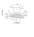
図2は、図1に記載した空気入りタイヤのトレッド部を示す拡大図である。同図は、タイヤ赤道面CLを境界とする車幅方向外側領域の拡大図を示している。同図において、符号Tは、接地端である。また、図3は、図2に記載した最外周方向主溝22の溝下領域Aiを示す拡大図である。同図は、溝下領域Aiにおける交差ベルト141、142およびカーカス層13のプロファイルの湾曲構造を示している。図4は、図2に記載した外側交差ベルト142を示す説明図である。同図は、単体の外側交差ベルト142のタイヤ子午線方向の断面図を示している。
FIG. 2 is an enlarged view showing a tread portion of the pneumatic tire shown in FIG. 1. This figure shows an enlarged view of the outer region in the vehicle width direction with the tire equatorial plane CL as a boundary. In the figure, the symbol T is a ground terminal. FIG. 3 is an enlarged view showing a sub-groove region Ai of the outermost circumferential
図2に示すように、タイヤ子午線方向の断面視にて、外側交差ベルト142のプロファイルPrが、タイヤ内腔側に凸となる形状を有すると共に最外周方向主溝22の溝下領域Aiに位置する溝下プロファイル部Pri(図2の曲率半径Riを有する部分)と、タイヤ径方向外側に凸となる形状を有すると共に溝下プロファイル部Priのタイヤ幅方向内側端部に接続する第一プロファイル部(図2の曲率半径Ro1を有する部分。図中の符号省略。)と、タイヤ径方向外側に凸となる形状を有すると共に溝下プロファイル部Priのタイヤ幅方向外側端部に接続する第二プロファイル部(図2の曲率半径Ro2を有する部分。図中の符号省略。)とを備える。すなわち、外側交差ベルト142のプロファイルPrが、最外周方向主溝22の溝下領域Aiにてタイヤ内腔側に凸となり、溝下領域Aiの左右の領域にてタイヤ径方向外側に凸となる。また、外側交差ベルト142のプロファイルPrが、タイヤ全周に渡って一様な形状を有する。
As shown in FIG. 2, the profile Pr of the
プロファイルは、タイヤ子午線方向の断面視における輪郭線であり、タイヤを規定リムに装着して規定内圧を充填した無負荷状態にてレーザープロファイラを用いて計測される。レーザープロファイラとしては、例えば、タイヤプロファイル測定装置(株式会社マツオ製)が使用される。特に、外側交差ベルト142のプロファイルPrは、図4に示すように、外側交差ベルト142のベルトコード1421のタイヤ径方向外側の周面を滑らかに接続した曲線として定義される。
The profile is a contour line in a sectional view in the tire meridian direction, and is measured using a laser profiler in a no-load state in which the tire is mounted on a specified rim and filled with a specified internal pressure. As the laser profiler, for example, a tire profile measuring device (manufactured by Matsuo Corporation) is used. In particular, as shown in FIG. 4, the profile Pr of the
また、溝下プロファイル部Pri、第一プロファイル部および第二プロファイル部は、単一の円弧から構成されても良いし、滑らかに接続された複数の円弧から構成されても良い。溝下プロファイル部Priが複数の円弧から成る場合には、溝下プロファイル部Priをタイヤ内腔側に凸となる単一の円弧で近似して、後述する溝下プロファイル部Priの曲率半径Riが測定される。同様に、第一プロファイル部および第二プロファイル部が複数の円弧から成る場合には、各プロファイル部をタイヤ径方向外側に凸となる単一の円弧で近似して、後述する溝下プロファイル部Priの曲率半径Ro1、Ro2が測定される。 Further, the sub-groove profile portion Pri, the first profile portion, and the second profile portion may be composed of a single arc or a plurality of smoothly connected arcs. When the under-groove profile portion Pri is composed of a plurality of arcs, the under-groove profile portion Pri is approximated by a single arc that protrudes toward the tire lumen, and a curvature radius Ri of the below-groove profile portion Pri described later is obtained. Measured. Similarly, when the first profile portion and the second profile portion are composed of a plurality of arcs, each profile portion is approximated by a single arc that protrudes outward in the tire radial direction, and a below-groove profile portion Pri described later. The curvature radii Ro1 and Ro2 are measured.
溝下領域Aiは、上記のように最外周方向主溝22のタイヤ内腔部側に位置する領域であり、図2に示すように、タイヤ子午線方向の断面視にて、最外周方向主溝22の左右の開口端部をそれぞれ通りトレッド面のプロファイルに垂直な一つの直線の間の領域として定義される。最外周方向主溝22の左右の開口端部は、図3に示すように、後述する最外周方向主溝22の溝幅GWの測定点として定義される。
The sub-groove region Ai is a region located on the tire lumen side of the outermost circumferential
溝下プロファイル部Priは、上記のようにタイヤ内腔側に凸となる形状を有し、最外周方向主溝22の溝下領域Aiに位置する(図2参照)。このとき、溝下プロファイル部Priの全体が溝下領域Aiに含まれても良いし、溝下プロファイル部Priの一方あるいは双方の端部が溝下領域Aiの境界線を越えてタイヤ幅方向外側に突出しても良い。例えば、図2の構成では、溝下プロファイル部Priの両端部と溝下領域Aiの左右の境界線とが略同位置にある。 The sub-groove profile portion Pri has a convex shape toward the tire lumen as described above, and is located in the sub-groove region Ai of the outermost circumferential main groove 22 (see FIG. 2). At this time, the entirety of the under-groove profile portion Pri may be included in the under-groove region Ai, or one or both ends of the under-groove profile portion Pri exceed the boundary of the under-groove region Ai and are outside in the tire width direction. You may project it. For example, in the configuration of FIG. 2, both end portions of the lower groove profile portion Pri and the left and right boundary lines of the lower groove region Ai are substantially at the same position.
また、溝下プロファイル部Priの曲率半径Riが、10[mm]≦Ri≦50[mm]の範囲にあることが好ましく、15[mm]≦Ri≦30[mm]の範囲にあることがより好ましい。図2の構成では、溝下プロファイル部Priがタイヤ内腔側に凸となる単一円弧から成り、曲率半径Riの中心が最外周方向主溝22の溝中心線上にある。しかし、これに限らず、例えば、最外周方向主溝22が左右非対称な断面形状を有するときに、曲率半径Riの中心が最外周方向主溝22の溝中心線から離間しても良い(図示省略)。
The curvature radius Ri of the sub-groove profile portion Pri is preferably in the range of 10 [mm] ≦ Ri ≦ 50 [mm], and more preferably in the range of 15 [mm] ≦ Ri ≦ 30 [mm]. preferable. In the configuration of FIG. 2, the sub-groove profile portion Pri is formed of a single arc that protrudes toward the tire lumen, and the center of the curvature radius Ri is on the groove center line of the outermost circumferential
第一プロファイル部は、上記のようにタイヤ径方向外側に凸となる曲率半径Ro1を有し、溝下プロファイル部Priのタイヤ幅方向内側に位置する(図2参照)。このとき、第一プロファイル部とセカンド陸部32の踏面のプロファイルとが、タイヤ幅方向に相互にラップする。図2の構成では、第一プロファイル部が、溝下プロファイル部Priのタイヤ幅方向内側の端部からタイヤ赤道面CLを越えて延在することにより、センター陸部31およびセカンド陸部32の双方に跨って延在している。しかし、これに限らず、第一プロファイル部は、少なくとも溝下プロファイル部Priとの接続位置からセカンド陸部32のタイヤ幅方向内側のエッジ部までの領域に渡って延在すれば足りる。したがって、外側交差ベルト142のプロファイルPrが、セカンド陸部32よりもタイヤ赤道面CL側の領域にて、タイヤ内腔部側に凸となる形状を有しても良い(図示省略)。
As described above, the first profile portion has a curvature radius Ro1 that protrudes outward in the tire radial direction, and is positioned on the inner side in the tire width direction of the lower groove profile portion Pri (see FIG. 2). At this time, the first profile portion and the profile of the tread surface of the
また、第一プロファイル部の曲率半径Ro1が、150[mm]≦Ro1≦2000[mm]の範囲にあることが好ましく、400[mm]≦Ro1≦1200[mm]の範囲にあることがより好ましい。図2の構成では、第一プロファイル部がタイヤ径方向外側に凸となる単一円弧から成り、曲率半径Ro1の中心がタイヤ赤道面CL上にある。しかし、これに限らず、例えば、第一プロファイル部がタイヤ径方向外側に凸となる複数の円弧から成ることにより、第一プロファイル部の曲率半径Ro1がセンター陸部31の位置とセカンド陸部32の位置とで変化しても良い(図示省略)。
Moreover, it is preferable that the curvature radius Ro1 of a 1st profile part exists in the range of 150 [mm] <= Ro1 <= 2000 [mm], and it is more preferable to exist in the range of 400 [mm] <= Ro1 <= 1200 [mm]. . In the configuration of FIG. 2, the first profile portion is composed of a single arc that protrudes outward in the tire radial direction, and the center of the curvature radius Ro1 is on the tire equatorial plane CL. However, the present invention is not limited to this. For example, when the first profile portion is formed of a plurality of arcs that protrude outward in the tire radial direction, the radius of curvature Ro1 of the first profile portion is equal to the position of the
第二プロファイル部は、上記のようにタイヤ径方向外側に凸となる曲率半径Ro2を有し、溝下プロファイル部Priのタイヤ幅方向外側に位置する(図2参照)。このとき、第二プロファイル部とショルダー陸部33の踏面のプロファイルとが、タイヤ幅方向に相互にラップする。図2の構成では、第二プロファイル部が、溝下プロファイル部Priのタイヤ幅方向外側の端部から接地端Tを越えて外側交差ベルト142のタイヤ幅方向外側のエッジ部まで延在している。しかし、これに限らず、第二プロファイル部は、少なくとも溝下プロファイル部Priとの接続位置から接地端Tまでの領域に渡って延在すれば足りる。したがって、外側交差ベルト142のプロファイルPrが、タイヤ接地端Tよりもタイヤ幅方向外側の領域にて、タイヤ内腔部側に凸となる形状を有しても良い(図示省略)。
As described above, the second profile portion has a curvature radius Ro2 that is convex outward in the tire radial direction, and is positioned on the outer side in the tire width direction of the lower groove profile portion Pri (see FIG. 2). At this time, the profile of the second profile portion and the tread surface of the
また、第二プロファイル部の曲率半径Ro2が、50[mm]≦Ro2≦800[mm]の範囲にあることが好ましく、200[mm]≦Ro2≦600[mm]の範囲にあることがより好ましい。図2の構成では、第二プロファイル部がタイヤ径方向外側に凸となる単一円弧から成り、曲率半径Ro2の中心がタイヤ赤道面CL上にある。しかし、これに限らず、第二プロファイル部がタイヤ径方向外側に凸となる複数の円弧から成ることにより、第二プロファイル部の曲率半径Ro2がショルダー陸部33内で変化しても良い(図示省略)。
The curvature radius Ro2 of the second profile portion is preferably in the range of 50 [mm] ≦ Ro2 ≦ 800 [mm], and more preferably in the range of 200 [mm] ≦ Ro2 ≦ 600 [mm]. . In the configuration of FIG. 2, the second profile portion is formed of a single arc that protrudes outward in the tire radial direction, and the center of the curvature radius Ro2 is on the tire equatorial plane CL. However, the present invention is not limited to this, and the curvature radius Ro2 of the second profile portion may change in the
また、上記のように第一プロファイル部および第二プロファイル部が溝下プロファイル部Priの左右の端部にそれぞれ接続する(図2参照)。このとき、図3に示すように、溝下プロファイル部Priと第一プロファイル部および第二プロファイル部とが相互に直接的に接続されても良いし、円弧形状、S字形状あるいは直線形状を有する短尺な接続部(図示省略)を介して滑らかに接続されても良い。 Further, as described above, the first profile portion and the second profile portion are respectively connected to the left and right end portions of the lower groove profile portion Pri (see FIG. 2). At this time, as shown in FIG. 3, the lower groove profile portion Pri and the first profile portion and the second profile portion may be directly connected to each other, or have an arc shape, an S shape, or a linear shape. You may connect smoothly via a short connection part (illustration omitted).
また、溝下プロファイル部Priと第一プロファイル部および第二プロファイル部との接続部が次の条件を満たすことが好ましい。すなわち、図3に示すように、タイヤ子午線方向の断面視にて、第一プロファイル部および第二プロファイル部に接する仮想円弧(図3中の破線)と、この仮想円弧上における第一プロファイル部および第二プロファイル部の溝下プロファイル部Pri側の端点P1、P2を定義する。このとき、最外周方向主溝22の溝中心線から端点P1、P2までの距離Wb(図3では、Wb1およびWb2)と最外周方向主溝22の溝幅GWとが、0.40≦Wb/GW≦0.80の関係を有することが好ましく、0.50≦Wb/GW≦0.65の関係を有することがより好ましい。
In addition, it is preferable that the connection portion between the sub-groove profile portion Pri and the first profile portion and the second profile portion satisfy the following condition. That is, as shown in FIG. 3, in a sectional view in the tire meridian direction, a virtual arc (broken line in FIG. 3) in contact with the first profile portion and the second profile portion, and the first profile portion on the virtual arc and The end points P1 and P2 on the lower profile portion Pri side of the second profile portion are defined. At this time, the distance Wb (Wb1 and Wb2 in FIG. 3) from the groove center line of the outermost circumferential
さらに、タイヤ幅方向外側の端点P2が、タイヤ接地端T(図2参照)よりもタイヤ幅方向内側にあることが好ましい。 Furthermore, it is preferable that the end point P2 on the outer side in the tire width direction is on the inner side in the tire width direction than the tire ground contact end T (see FIG. 2).
タイヤ接地端Tは、タイヤを規定リムに装着して規定内圧を付与すると共に静止状態にて平板に対して垂直に置いて規定荷重に対応する負荷を加えたときのタイヤと平板との接触面におけるタイヤ軸方向の最大幅位置として定義される。 The tire ground contact end T is a contact surface between the tire and the flat plate when a tire is mounted on a predetermined rim to apply a predetermined internal pressure and a load corresponding to the predetermined load is applied in a stationary state perpendicular to the flat plate. Is defined as the maximum width position in the tire axial direction.
また、前記仮想円弧を基準とする溝下プロファイル部Priの最大突出量Dが、0.6[mm]≦D≦3.3[mm]の範囲にあることが好ましく、1.4[mm]≦D≦2.4[mm]の範囲にあることがより好ましい。 Moreover, it is preferable that the maximum protrusion amount D of the lower groove profile portion Pri with respect to the virtual arc is in a range of 0.6 [mm] ≦ D ≦ 3.3 [mm], and 1.4 [mm] More preferably, it is in the range of ≦ D ≦ 2.4 [mm].
また、前記仮想円弧を基準とする溝下プロファイル部Priの最大突出量Dと、最外周方向主溝22の溝下ゲージG1とが、0.40≦D/(G1−D)≦1.70の関係を有することが好ましく、0.60≦D/(G1−D)≦1.50の関係を有することがより好ましい。
Further, the maximum protrusion amount D of the lower groove profile portion Pri with respect to the virtual arc and the lower groove gauge G1 of the outermost circumferential
また、センター周方向主溝21の溝下ゲージG1’(図中の符号省略)と、最外周方向主溝22の溝下ゲージG1とが、0.6[mm]≦G1−1’の関係を有することが好ましく、0.6[mm]≦G1−1’の関係を有することがより好ましい。差G1−1’の上限は、特に限定がないが、溝下プロファイル部Priの最大突出量Dおよび最外周方向主溝22の溝下ゲージG1との関係により制約を受ける。
Further, the relationship between the sub-gage gauge G1 ′ (not shown in the drawing) of the center circumferential
最大突出量Dは、トレッドプロファイルに垂直な方向における溝下プロファイル部Priの突出量の最大値として定義される。 The maximum protrusion amount D is defined as the maximum value of the protrusion amount of the sub-groove profile portion Pri in the direction perpendicular to the tread profile.
溝下ゲージG1、G1’(および後述するG2)は、周方向主溝の溝底と、周方向主溝の溝下にあるベルト層の最外層のベルトコード(より具体的には、最外層のベルトコードのタイヤ径方向外側の頂部を結ぶ円弧)との距離として測定される。図3では、最外周方向主溝22の溝下におけるベルト層14の最外層が外側交差ベルト142であるため、最外周方向主溝22の溝底から外側交差ベルト142のベルトコードまでの距離が溝下ゲージG1として測定される。また、例えば、最外周方向主溝22の溝下にベルトカバーが配置された構成(図示省略)では、最外周方向主溝22の溝底からベルトカバーのベルトコードまでの距離が溝下ゲージG1として測定される。すなわち、溝下ゲージG1は、最外周方向主溝22の溝下におけるトレッドゴム15のゲージとして定義される。
The sub-groove gauges G1 and G1 ′ (and G2 to be described later) are a belt cord (more specifically, an outermost layer) of the outermost layer of the belt layer below the groove of the circumferential main groove and the groove of the circumferential main groove. The distance between the belt cord and a circular arc connecting the apexes on the outer side in the tire radial direction is measured. In FIG. 3, since the outermost layer of the
また、図4において、乗用車用タイヤでは、外側交差ベルト142のベルトコード1421の外径φが、0.23[mm]≦φ≦0.30[mm]の範囲にある。なお、図4における符号1422は、外側交差ベルト142のコートゴムである。
In FIG. 4, in the passenger car tire, the outer diameter φ of the
ベルトコードの外径は、コードが撚り合わされた複数本のフィラメントから成る構成では、コードの径方向断面視における外接円の直径として測定される。 The outer diameter of the belt cord is measured as the diameter of a circumscribed circle in a radial cross-sectional view of the cord in a configuration including a plurality of filaments in which the cord is twisted.
上記の構成では、外側交差ベルト142のプロファイルPrがタイヤ内腔側に凸となる溝下プロファイル部Priを最外周方向主溝22の溝下領域Aiに備えるので、最外周方向主溝22の溝底から外側交差ベルト142までの溝底ゲージG1が確保される。これにより、グルーブクラックの成長に起因する外側交差ベルト142の損傷が抑制されて、タイヤのベルト耐久性能が向上する。
In the above-described configuration, the groove Pr of the outermost circumferential
[変形例]
図5は、図1に記載した空気入りタイヤの変形例を示す説明図である。同図は、最外周方向主溝22の溝下領域Aiの拡大図を示している。
[Modification]
FIG. 5 is an explanatory view showing a modified example of the pneumatic tire shown in FIG. 1. This figure shows an enlarged view of the sub-groove region Ai of the outermost circumferential
図1の構成では、図3に示すように、ベルト層14の最外層が外側交差ベルト142であり、外側交差ベルト142の外周にトレッドゴム15が配置されている。また、最外周方向主溝22の溝下領域Aiでは、外側交差ベルト142の外周にアンダートレッド152が位置し、アンダートレッド152の外周にキャップトレッド151が位置している。このため、外側交差ベルト142の溝下プロファイル部Priの凹みには、アンダートレッド152が充填されている。
In the configuration of FIG. 1, as shown in FIG. 3, the outermost layer of the
これに対して、図5の構成では、トレッドゴム15に対して異なる物性を有する溝下ゴム19が、外側交差ベルト142の溝下プロファイル部Priの凹みに配置される。
In contrast, in the configuration of FIG. 5, the under-
具体的には、溝下ゴム19が、アンダートレッド152よりも耐発熱性に優れた物性を有する。例えば、図5の構成では、キャップトレッド151のtanδ値が0.03以上00.30以下の範囲にあり、アンダートレッド152のtanδ値が0.05以上0.25以下の範囲にある。そして、溝下ゴム19のtanδ値がアンダートレッド152のtanδ値に対して105[%]以上130[%]以下の範囲にあることが好ましく、110[%]以上120[%]以下の範囲にあることがより好ましい。
Specifically, the under-
また、溝下ゴム19が、第一プロファイル部および第二プロファイル部に接する仮想円弧と外側交差ベルト142の外周面とに囲まれた領域に配置される。例えば、図5の構成では、溝下ゴム19が、最外周方向主溝22の溝下領域Aiにて、アンダートレッド152と外側交差ベルト142の外周面との間に挟み込まれて配置されている。これにより、溝下ゴム19が外側交差ベルト142の溝下プロファイル部Priの凹みに充填されている。
Further, the
tanδ値は、(株)東洋精機製作所製の粘弾性スペクトロメーターを用いて、温度60[℃]、剪断歪み10[%]、振幅±0.5[%]および周波数20[Hz]の条件で測定される。 The tan δ value was measured using a viscoelastic spectrometer manufactured by Toyo Seiki Seisakusho under the conditions of temperature 60 [° C.], shear strain 10 [%], amplitude ± 0.5 [%], and frequency 20 [Hz]. Measured.
上記の構成では、タイヤ転動時にて、溝下ゴム19が最外周方向主溝22の溝下領域Aiでの発熱を抑制するので、溝下領域Aiのゴムの劣化に起因するグルーブクラックの成長が抑制される。これにより、グルーブクラックによる外側交差ベルト142の損傷が抑制される。
In the above configuration, when the tire rolls, the
なお、上記の構成では、タイヤ子午線方向の断面視にて、溝下ゴム19が、上記囲まれた領域の断面積の40[%]以上を埋めて配置されることが好ましく、60[%]以上を埋めて配置されることがより好ましい。
In the above-described configuration, it is preferable that the under-
また、タイヤ子午線方向の断面視にて、溝下ゴム19の厚みG2と最外周方向主溝22の溝下ゲージG1とが、0.6≦G2/G1≦1.0の範囲にあることが好ましく、0.7≦G2/G1≦0.9の範囲にあることがより好ましい。G2/G1≦1.0は、溝下ゴム19が外側交差ベルト412の外周面から最外周方向主溝22の溝底まで延在して最外周方向主溝22の溝底に露出した状態を意味する。
In addition, the thickness G2 of the under-
また、タイヤ子午線方向の断面視にて、溝下ゴム19の幅Wgと最外周方向主溝22の幅GWとが、0.7≦Wg/GW≦2.0の範囲にあることが好ましく、1.0≦Wg/GW≦1.6の範囲にあることがより好ましい。
In addition, the width Wg of the under-
溝下ゴム19の厚みG2および幅Wgは、タイヤを規定リムに装着して規定内圧を付与すると共に無負荷状態として測定される。また、厚みG2は、トレッドプロファイルに垂直な方向における溝下ゴム19の厚みの最大値として測定される。また、幅Wgは、溝中心線に対して垂直な方向における溝下ゴム19の幅の最大値として測定される。
The thickness G2 and the width Wg of the under-
また、図2の構成では、タイヤ径方向内側にある内側交差ベルト141のプロファイル(図中の符号省略)が、溝下プロファイル部Priに沿ってタイヤ内腔側に凸となるプロファイル部を有している。さらに、カーカス層13のプロファイルが、溝下プロファイル部Priに沿ってタイヤ内腔側に凸となるプロファイル部を有している。このため、最外周方向主溝22の溝下領域Aiでは、カーカス層13および一対の交差ベルト141、142のすべてのプロファイルが、タイヤ内腔部側に凸となるように部分的に湾曲した形状を有している。かかる構成では、カーカス層13および一対の交差ベルト141、142のコード間距離を密にしつつ、溝下領域Aiにおける外側交差ベルト142の凹みを適正に形成できる点で好ましい。
In the configuration of FIG. 2, the profile of the
しかし、これに限らず、溝下領域Aiにて、外側交差ベルト142のプロファイルPrのみがタイヤ内腔部側に凸となるように部分的に湾曲した形状を有し、カーカス層13および内側交差ベルト141のプロファイルがタイヤ径方向外側に凸となる形状を有しても良い(図示省略)。あるいは、一対の交差ベルト141、142のプロファイルがタイヤ内腔部側に凸となるように部分的に湾曲した形状を有し、カーカス層13のプロファイルがタイヤ径方向外側に凸となる形状を有しても良い(図示省略)。
However, the present invention is not limited to this, and in the sub-groove region Ai, only the profile Pr of the
また、図1の構成では、溝下プロファイル部Priが、車幅方向外側の最外周方向主溝22の溝下のみに形成され、車幅方向内側の最外周方向主溝22の溝下には形成されていない。このため、外側交差ベルト142のプロファイルPrが、タイヤ赤道面CLを境界とする車幅方向内側領域の全体でタイヤ径方向外側に凸となる形状を有している。一般にグルーブクラックは、車幅方向外側領域の最外周方向主溝22に発生し易い。このため、溝下プロファイル部Priが車幅方向外側の最外周方向主溝22の溝下に形成されることにより、グルーブクラックに起因する外側交差ベルト142の損傷を適正に抑制できる。
In the configuration of FIG. 1, the lower groove profile portion Pri is formed only below the outermost circumferential
また、上記のように溝下プロファイル部Priが車幅方向外側の最外周方向主溝22の溝下のみに形成される構成では、空気入りタイヤ1が、溝下プロファイル部Priを有する側を車幅方向外側にして車両に装着することを指定する装着方向表示部(図示省略)を有することが好ましい。装着方向表示部は、例えば、タイヤのサイドウォール部に付されたマークや凹凸によって構成される。例えば、ECER30(欧州経済委員会規則第30条)が、車両装着状態にて車幅方向外側となるサイドウォール部に装着方向表示部を設けることを義務付けている。
In the configuration in which the lower groove profile portion Pri is formed only under the outermost circumferential
しかし、これに限らず、外側交差ベルト142のプロファイルPrが、左右の最外周方向主溝22、22の溝下に、それぞれ溝下プロファイル部Priを備えても良い(図示省略)。
However, the present invention is not limited to this, and the profile Pr of the
また、図2に示すように、最外周方向主溝22が、タイヤ赤道面CLからタイヤ接地半幅TW/2の40[%]以上80[%]以下の距離にあることが好ましい。
In addition, as shown in FIG. 2, the outermost circumferential
タイヤ接地幅TWは、タイヤを規定リムに装着して規定内圧を付与すると共に静止状態にて平板に対して垂直に置いて規定荷重に対応する負荷を付与したときのタイヤと平板との接触面におけるタイヤ軸方向の最大直線距離として測定される。 The tire ground contact width TW is the contact surface between the tire and the flat plate when the tire is mounted on the specified rim to apply the specified internal pressure and is placed perpendicular to the flat plate in a stationary state and applied with a load corresponding to the specified load. It is measured as the maximum linear distance in the tire axial direction.
[タイヤ製造方法]
一般的な空気入りタイヤ1は、次の製造工程により製造される。まず、ビードコア11を構成するビードワイヤ、カーカス層13を構成するカーカスプライ、ベルト層14を構成するベルトプライ141〜143、トレッドゴム15、サイドウォールゴム16、リムクッションゴム17などの各部材が成形機にかけられて、グリーンタイヤ(図示省略)が成形される。次に、このグリーンタイヤがタイヤ加硫モールド(図示省略)に充填される。次に、この加硫モールドが加熱され、加圧装置によりグリーンタイヤが径方向外方に拡張されてタイヤ加硫モールドのタイヤ成形金型(特に、トレッド面成形部)に当接する。次に、グリーンタイヤが加熱されることにより、トレッド部のゴム分子と硫黄分子とが結合して加硫が行われる。このとき、タイヤ成形金型の形状がグリーンタイヤのトレッド面に転写されて、空気入りタイヤ1のトレッドパターンが成形される。その後に、加硫後のタイヤが、タイヤ加硫モールドから引き抜かれて取り出される。
[Tire manufacturing method]
The general pneumatic tire 1 is manufactured by the following manufacturing process. First, each member such as a bead wire constituting the
上記の製造工程において、外側交差ベルト142のプロファイルPrは、例えば、以下の工程により成形できる。まず、グリーンタイヤの成形工程にて、外側交差ベルト142の最外周方向主溝22に対応する位置に溝下プロファイル部Priを構成する凹みを予め形成する。例えば、カーカス層13の外周に交差ベルト141、142を配置した後に、外側交差ベルト142の一部を外周面側から押圧して凹ませても良いし、予め湾曲して凹みを有する外側交差ベルト142をカーカス層13に積層して配置しても良い。その後に、外側交差ベルト142の外周にトレッドゴム15を配置して、タイヤの加硫成形工程を行う。すると、加硫成形時に、タイヤ成形金型のブレードがトレッドゴム15を押圧することにより、トレッドゴム15が外側交差ベルト142の凹みに充填される。これにより、タイヤ子午線方向の断面視にて、タイヤ内腔部側に凸となる外側交差ベルト142の溝下プロファイル部Priが形成される。
In the above manufacturing process, the profile Pr of the
[効果]
以上説明したように、この空気入りタイヤ1は、カーカス層13と、カーカス層13の外周に配置された一対の交差ベルト141、142と、一対の交差ベルト141、142の外周に配置されたトレッドゴム15と、タイヤ周方向に延在する複数の周方向主溝21、22と、周方向主溝21、22に区画されて成る複数の陸部31〜33とを備える(図1参照)。また、タイヤ子午線方向の断面視にて、外側交差ベルト142のプロファイルPrが、タイヤ内腔側に凸となる形状を有すると共に最外周方向主溝22の溝下領域Aiに位置する溝下プロファイル部Pri(図2では、曲率半径Riを有する部分)と、タイヤ径方向外側に凸となる形状を有すると共に溝下プロファイル部Priのタイヤ幅方向内側端部に接続する第一プロファイル部(図2では、曲率半径Ro1を有する部分。図中の符号省略。)と、タイヤ径方向外側に凸となる形状を有すると共に溝下プロファイル部Priのタイヤ幅方向外側端部に接続する第二プロファイル部(図2では、曲率半径Ro2を有する部分。図中の符号省略。)とを備える(図2参照)。
[effect]
As described above, the pneumatic tire 1 includes the
かかる構成では、(1)外側交差ベルト142のプロファイルPrがタイヤ内腔側に凸となる溝下プロファイル部Priを最外周方向主溝22の溝下領域Aiに備えるので、最外周方向主溝22の溝底から外側交差ベルト142までの溝底ゲージG1が増加する。これにより、グルーブクラックの成長に起因する外側交差ベルト142の損傷が抑制されて、タイヤのベルト耐久性能が向上する利点がある。
In such a configuration, (1) since the profile Pr of the
また、(2)外側交差ベルト142のプロファイルPrがタイヤ内腔側に凸となる溝下プロファイル部Priを最外周方向主溝22の溝下領域Aiに部分的に備えるので、トレッド全体の周方向主溝の溝下ゲージを増加させる構成(図示省略)と比較して、トレッドゴム15のボリュームを低減できる。これにより、タイヤの転がり抵抗を適正に確保できる利点がある。
Further, (2) since the profile Pr of the
また、(3)外側交差ベルト142のプロファイルPrがタイヤ径方向外側に凸となる第一プロファイル部および第二プロファイル部を溝下プロファイル部Priの左右に備えるので、最外周方向主溝22を境界とするトレッド部センター領域およびショルダー領域の接地形状が適正に確保される。これにより、タイヤの転がり抵抗が適正に確保される利点がある。
(3) Since the profile Pr of the
また、この空気入りタイヤ1では、最外周方向主溝22が、タイヤ赤道面CLを境界とする少なくとも一方の領域であってタイヤ赤道面CLからタイヤ接地半幅TW/2の40[%]以上80[%]以下の距離に配置される(図2参照)。かかる位置にある最外周方向主溝22では、グルーブクラックが発生し易い傾向にある。したがって、かかる最外周方向主溝22の溝底領域Aiに、外側交差ベルト142のプロファイルPrがタイヤ内腔側に凸となる溝下プロファイル部Priを備えることにより、グルーブクラックの成長に起因する外側交差ベルト142の損傷が効果的に抑制される利点がある。
Further, in this pneumatic tire 1, the outermost circumferential
また、この空気入りタイヤ1では、溝下プロファイル部Priの曲率半径Ri(図2参照)が、10[mm]≦Ri≦50[mm]の範囲にある。これにより、溝下プロファイル部Priの曲率半径Riが適正化される利点がある。すなわち、10[mm]≦Riであることにより、曲率半径Riが確保されて溝下プロファイル部Priの形状が緩やかになり、外側交差ベルト142のプロファイルPrの形状が適正に確保される。また、Ri≦50[mm]であることにより、曲率半径Riが小さく設定されて、溝下プロファイル部Priの最大突出量D(図3参照)が確保される。これにより、最外周方向主溝22の溝下ゲージG1が確保されて、溝下プロファイル部Priの機能が適正に確保される。
Moreover, in this pneumatic tire 1, the curvature radius Ri (see FIG. 2) of the lower groove profile portion Pri is in the range of 10 [mm] ≦ Ri ≦ 50 [mm]. Thereby, there exists an advantage by which the curvature radius Ri of the groove part profile Pri is optimized. That is, by satisfying 10 [mm] ≦ Ri, the radius of curvature Ri is ensured, the shape of the profile portion Pri below the groove is moderate, and the shape of the profile Pr of the
また、この空気入りタイヤ1では、第一プロファイル部の曲率半径Ro1(図2参照)が、150[mm]≦Ro1≦2000[mm]の範囲にある。これにより、最外周方向主溝22を境界とするトレッド部センター領域の接地形状が適正化される利点がある。すなわち、150[mm]≦Ro1であることにより、曲率半径Ro1が確保されて、接地形状がタイヤ周方向に縦長となる事態が抑制される。また、Ro1≦2000[mm]であることにより、曲率半径Ro1が過大となることが抑制されて、トレッド部センター領域の接地圧がショルダー領域の接地圧よりも低くなる事態が抑制される。 Moreover, in this pneumatic tire 1, the curvature radius Ro1 (refer FIG. 2) of the 1st profile part exists in the range of 150 [mm] <= Ro1 <= 2000 [mm]. Thereby, there exists an advantage by which the contact shape of the tread part center area | region which makes the outermost peripheral direction main groove 22 a boundary is optimized. That is, by satisfying 150 [mm] ≦ Ro1, the curvature radius Ro1 is ensured, and the situation where the ground contact shape is vertically long in the tire circumferential direction is suppressed. Moreover, since it is Ro1 <= 2000 [mm], it is suppressed that the curvature radius Ro1 becomes excessive, and the situation where the contact pressure of a tread part center area | region becomes lower than the contact pressure of a shoulder area | region is suppressed.
また、この空気入りタイヤ1では、第二プロファイル部の曲率半径Ro2(図2参照)が、50[mm]≦Ro2≦800[mm]の範囲にある。これにより、最外周方向主溝22を境界とするトレッド部ショルダー領域の接地形状が適正化される利点がある。すなわち、50[mm]≦Ro2であることにより、曲率半径Ro2が確保されて、接地幅がサイズの適正値と比較して狭くなる事態が抑制される。また、Ro2≦800[mm]であることにより、曲率半径Ro2が過大となることが抑制されて、トレッド部ショルダー領域の接地圧がセンター領域の接地圧と比較して著しく高くなる事態が抑制される。 In this pneumatic tire 1, the radius of curvature Ro2 (see FIG. 2) of the second profile portion is in the range of 50 [mm] ≦ Ro2 ≦ 800 [mm]. Thereby, there exists an advantage by which the contact shape of the tread part shoulder area | region which makes the outermost peripheral direction main groove 22 a boundary is optimized. That is, by satisfying 50 [mm] ≦ Ro2, the curvature radius Ro2 is ensured, and a situation where the ground contact width becomes narrower than the appropriate value of the size is suppressed. Further, by satisfying Ro2 ≦ 800 [mm], it is suppressed that the radius of curvature Ro2 is excessive, and a situation in which the contact pressure in the tread shoulder region is significantly higher than the contact pressure in the center region is suppressed. The
また、この空気入りタイヤ1では、第一プロファイル部および第二プロファイル部に接する仮想円弧(図3の破線)と、仮想円弧上における第一プロファイル部および第二プロファイル部の溝下プロファイル部Pri側の端点P1、P2(図3参照)を定義するときに、最外周方向主溝22の溝中心線から端点P1、P2までの距離Wb(図3におけるWb1およびWb2)と、最外周方向主溝22の溝幅GWとが、0.40≦Wb/GW≦0.80の関係を有する。これにより、溝下プロファイル部Priの幅が適正化される利点がある。すなわち、0.40≦Wb/GWであることにより、溝下プロファイル部Priの幅が適正に確保されて、溝下プロファイル部Priの機能が確保される。また、Wb/GW≦0.80であることにより、溝下プロファイル部Priの幅が過大となる事態が抑制されて、第一プロファイル部および第二プロファイル部の領域が適正に確保される。
Further, in the pneumatic tire 1, a virtual arc (broken line in FIG. 3) in contact with the first profile portion and the second profile portion, and the lower profile portion Pri side of the first profile portion and the second profile portion on the virtual arc. When defining the end points P1 and P2 (see FIG. 3), the distance Wb (Wb1 and Wb2 in FIG. 3) from the groove center line of the outermost circumferential
また、この空気入りタイヤ1では、タイヤ幅方向外側の端点P2(図3参照)が、タイヤ接地端T(図2参照)よりもタイヤ幅方向内側にある。これにより、第二プロファイル部の領域が適正に確保される利点がある。 Moreover, in this pneumatic tire 1, the end point P2 (see FIG. 3) on the outer side in the tire width direction is on the inner side in the tire width direction than the tire ground contact end T (see FIG. 2). Thereby, there exists an advantage by which the area | region of a 2nd profile part is ensured appropriately.
また、この空気入りタイヤ1では、第一プロファイル部および第二プロファイル部に接する仮想円弧(図3の破線)を定義するときに、仮想円弧を基準とする溝下プロファイル部Priの最大突出量D(図3参照)が、0.6[mm]≦D≦3.3[mm]の範囲にある。これにより、溝下プロファイル部Priの最大突出量Dが適正化される利点がある。すなわち、0.6[mm]≦Dであることにより、最外周方向主溝22の溝下ゲージG1が確保されて、ベルト耐久性能の向上効果が確保される。また、D≦3.3[mm]であることにより、溝下ゲージG1が過大となる事態が抑制されて、タイヤの転がり抵抗の悪化が抑制される。
Further, in the pneumatic tire 1, when defining a virtual arc (broken line in FIG. 3) in contact with the first profile portion and the second profile portion, the maximum protrusion amount D of the sub-groove profile portion Pri with the virtual arc as a reference. (See FIG. 3) is in the range of 0.6 [mm] ≦ D ≦ 3.3 [mm]. Thereby, there exists an advantage by which the maximum protrusion amount D of the profile part Pri below a groove | channel is optimized. That is, by satisfying 0.6 [mm] ≦ D, the sub-groove gauge G1 of the outermost circumferential
また、この空気入りタイヤ1では、センター周方向主溝21の溝下ゲージG2(図中の符号省略)と、最外周方向主溝22の溝下ゲージG1(図3参照)とが、0.6[mm]≦G1−G2の関係を有する。これにより、最外周方向主溝22の溝下ゲージG1が適正に確保されて、ベルト耐久性能の向上効果が確保される利点がある。
Further, in this pneumatic tire 1, a sub-groove gauge G <b> 2 (not shown in the drawing) of the center circumferential
また、この空気入りタイヤ1では、第一プロファイル部および第二プロファイル部に接する仮想円弧(図3の破線)を定義するときに、仮想円弧を基準とする溝下プロファイル部Priの最大突出量Dと、最外周方向主溝22の溝下ゲージG1とが、0.40≦D/(G1−D)≦1.70の関係を有する(図3参照)。これにより、溝下プロファイル部Priの最大突出量Dが適正化される利点がある。すなわち、0.40≦D/(G1−D)であることにより、最大突出量Dにより溝下ゲージG1が適正に増加して、ベルト耐久性能の向上効果が適正に確保される。また、D/(G1−D)≦1.70であることにより、最大突出量Dが過大となる事態が抑制されて、外側交差ベルト142のプロファイルPrの形状が適正化される。
Further, in the pneumatic tire 1, when defining a virtual arc (broken line in FIG. 3) in contact with the first profile portion and the second profile portion, the maximum protrusion amount D of the sub-groove profile portion Pri with the virtual arc as a reference. And the sub-groove gauge G1 of the outermost circumferential
また、この空気入りタイヤ1では、トレッドゴム15が、トレッド面を形成するキャップトレッド151と、キャップトレッド151の下層に配置されるアンダートレッド152とを備える(図1参照)。また、空気入りタイヤ1が、アンダートレッド152よりも耐発熱性に優れた物性を有すると共に、第一プロファイル部および第二プロファイル部に接する仮想円弧(図5の破線)と外側交差ベルト142の外周面とに囲まれた領域に配置される溝下ゴム19を備える(図5参照)。かかる構成では、タイヤ転動時にて、溝下ゴム19が最外周方向主溝22の溝下領域Aiでの発熱を抑制するので、溝下領域Aiのゴムの劣化に起因するグルーブクラックの成長が抑制される。これにより、グルーブクラックによる外側交差ベルト142の損傷が抑制される利点がある。特に、溝下ゴム19が外側交差ベルト142の溝下プロファイル部Priの凹みを埋めて配置されることにより、大舵角での転舵時におけるベルト折れを抑制できる利点がある。
Moreover, in this pneumatic tire 1, the
また、この空気入りタイヤ1では、タイヤ径方向内側にある交差ベルト141のプロファイル(図中の符号省略)が、溝下プロファイル部Priに沿ってタイヤ内腔側に凸となるプロファイル部を有する(図3参照)。かかる構成では、一対の交差ベルト141、142のコード間距離を密にしつつ、溝下領域Aiにおける外側交差ベルト142の凹みを適正に形成できる利点がある。
Further, in this pneumatic tire 1, the profile of the
また、この空気入りタイヤ1では、カーカス層13のプロファイル(図中の符号省略)が、溝下プロファイル部Priに沿ってタイヤ内腔側に凸となるプロファイル部を有する(図3参照)。かかる構成では、カーカス層13と一対の交差ベルト141、142とのコード間距離を密にしつつ、溝下領域Aiにおける外側交差ベルト142の凹みを適正に形成できる利点がある。
Moreover, in this pneumatic tire 1, the profile of the carcass layer 13 (not shown in the figure) has a profile portion that protrudes toward the tire lumen along the lower groove profile portion Pri (see FIG. 3). In such a configuration, there is an advantage that the recess of the
また、この空気入りタイヤ1は、溝下プロファイル部Priを有する側を車幅方向外側にして車両に装着することを指定する装着方向表示部を備える(図1参照)。かかる構成では、グルーブクラックが発生し易い車幅方向外側の最外周方向主溝22の溝下領域Aiに、溝下プロファイル部Priが形成される。これにより、溝下プロファイル部Priによるベルト耐久性の向上作用を効果的に得られる利点がある。
The pneumatic tire 1 also includes a mounting direction display unit that designates mounting on the vehicle with the side having the lower groove profile portion Pri on the outside in the vehicle width direction (see FIG. 1). In such a configuration, the lower groove profile portion Pri is formed in the lower groove region Ai of the outermost circumferential
また、この空気入りタイヤ1の製造方法は、グリーンタイヤの成形工程にて、外側交差ベルト142の最外周方向主溝22に対応する位置に溝下プロファイル部Priを構成する凹みを形成するステップと、グリーンタイヤを加硫成形するステップとを備える。かかる構成では、タイヤ加硫成形工程の前に、溝下プロファイル部Priを構成する凹みを外側交差ベルト142に予め形成する。これにより、タイヤ内腔部側に凸となる溝下プロファイル部Priを、簡易に形成できる利点がある。
In addition, the method for manufacturing the pneumatic tire 1 includes a step of forming a recess that forms the groove lower profile portion Pri at a position corresponding to the outermost circumferential
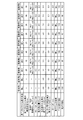
図6は、この発明の実施の形態にかかる空気入りタイヤの性能試験の結果を示す図表である。 FIG. 6 is a chart showing the results of the performance test of the pneumatic tire according to the embodiment of the present invention.
この性能試験では、複数種類の試験タイヤについて、(1)ベルト耐久性能および(2)転がり抵抗に関する評価が行われた。また、タイヤサイズ195/65R15 91Sの試験タイヤがリムサイズ15×6Jのリムに組み付けられ、この試験タイヤに230[kPa]の空気圧およびJATMA規定の最大負荷が付与される。また、試験タイヤが、試験車両である排気量1.6[L]の前輪駆動車の総輪に装着される。 In this performance test, (1) belt durability performance and (2) rolling resistance were evaluated for a plurality of types of test tires. Further, a test tire having a tire size of 195 / 65R15 91S is assembled to a rim having a rim size of 15 × 6 J, and an air pressure of 230 [kPa] and a maximum load specified by JATMA are applied to the test tire. In addition, the test tire is attached to all wheels of a front wheel drive vehicle having a displacement of 1.6 [L], which is a test vehicle.
(1)ベルト耐久性能に関する評価は、室内ドラム試験機を用いた低圧耐久試験により行われる。そして、走行速度を初速5[km/h]から12時間毎に1[km/h]ずつ増加させて、タイヤが故障するまでの走行時間が測定される。そして、この測定結果に基づいて従来例を基準(100)とした指数評価が行われる。この評価は、数値が大きいほど好ましい。 (1) The belt durability performance is evaluated by a low-pressure durability test using an indoor drum tester. Then, the travel speed is increased by 1 [km / h] every 12 hours from the initial speed of 5 [km / h], and the travel time until the tire breaks down is measured. Then, based on this measurement result, index evaluation using the conventional example as a reference (100) is performed. This evaluation is preferable as the numerical value increases.
(2)転がり抵抗に関する評価では、室内ドラム試験機が用いられ、速度50[km/h]時における抵抗力が測定されて評価が行われる。この評価は、従来例を基準(100)とした指数評価により行われ、その数値が大きいほど好ましい。また、数値が95以上であれば、転がり抵抗の悪化が適正に抑制されているといえる。 (2) In the evaluation relating to the rolling resistance, an indoor drum tester is used, and the resistance force at a speed of 50 km / h is measured and evaluated. This evaluation is performed by index evaluation using the conventional example as a reference (100), and the larger the value, the better. Moreover, if a numerical value is 95 or more, it can be said that deterioration of rolling resistance is suppressed appropriately.
実施例1〜7の試験タイヤは、図1〜図4の構成を備え、外側交差ベルト142のプロファイルPrが、車幅方向外側の最外周方向主溝22の溝下領域Aiに、タイヤ内腔部側に凸となる溝下プロファイル部Priを備える。また、最外周方向主溝22が、タイヤ接地半幅TW/2の70[%]の位置にあり、最外周方向主溝22の溝幅GWが、GW=10[mm]である。また、外側交差ベルト142の第一プロファイル部および第二プロファイル部の曲率半径Ro1、Ro2が、Ro1=500[mm]、Ro2=600[mm]である。また、実施例8の試験タイヤは、図5の構成を備え、最外周方向主溝22の溝下領域Aiに、溝下ゴム19を備える。また、アンダートレッド152のtanδ値が0.10であり、溝下ゴム19のtanδ値が0.05である。
The test tires of Examples 1 to 7 have the configurations of FIGS. 1 to 4, and the profile Pr of the
従来例1、2の試験タイヤは、実施例1の構成において、外側交差ベルト142のプロファイルPrが溝下プロファイル部Priを備えておらず、全域に渡ってタイヤ径方向外側に凸となる形状を備えている。また、外側交差ベルト142のプロファイルPrの曲率半径が、トレッド部センター領域で600[mm]であり、トレッド部ショルダー領域で800[mm]である。
The test tires of the conventional examples 1 and 2 have the configuration in which the profile Pr of the
試験結果に示すように、実施例1〜8の試験タイヤでは、タイヤの転がり抵抗を維持しつつベルト耐久性能が向上することが分かる。 As shown in the test results, it can be seen that in the test tires of Examples 1 to 8, the belt durability performance is improved while maintaining the rolling resistance of the tire.
1:空気入りタイヤ、11:ビードコア、12:ビードフィラー、13:カーカス層、131、132:カーカスプライ、14:ベルト層、141:内側交差ベルト、142:外側交差ベルト、1421:ベルトコード、1422:コートゴム、143:ベルトエッジカバー、15:トレッドゴム、151:キャップトレッド、152:アンダートレッド、16:サイドウォールゴム、17:リムクッションゴム、18:インナーライナ、19:溝下ゴム、21、22:周方向主溝、31〜33:陸部 1: pneumatic tire, 11: bead core, 12: bead filler, 13: carcass layer, 131, 132: carcass ply, 14: belt layer, 141: inner cross belt, 142: outer cross belt, 1421: belt cord, 1422 : Coat rubber, 143: Belt edge cover, 15: Tread rubber, 151: Cap tread, 152: Under tread, 16: Side wall rubber, 17: Rim cushion rubber, 18: Inner liner, 19: Rubber under groove, 21, 22 : Circumferential main groove, 31-33: Land
Claims (15)
タイヤ径方向外側にある前記交差ベルトを外側交差ベルトとして定義し、タイヤ幅方向の最も外側にある前記周方向主溝を最外周方向主溝として定義するときに、
タイヤ子午線方向の断面視にて、前記外側交差ベルトのプロファイルが、タイヤ内腔側に凸となる形状を有すると共に前記最外周方向主溝の溝下領域に位置する溝下プロファイル部と、タイヤ径方向外側に凸となる形状を有すると共に前記溝下プロファイル部のタイヤ幅方向内側端部に接続する第一プロファイル部と、タイヤ径方向外側に凸となる形状を有すると共に前記溝下プロファイル部のタイヤ幅方向外側端部に接続する第二プロファイル部とを備えることを特徴とする空気入りタイヤ。 A carcass layer, a pair of intersecting belts disposed on an outer periphery of the carcass layer, a tread rubber disposed on an outer periphery of the pair of intersecting belts, a plurality of circumferential main grooves extending in a tire circumferential direction, A pneumatic tire comprising a plurality of land portions divided into circumferential main grooves,
When defining the intersecting belt on the outer side in the tire radial direction as an outer intersecting belt, and defining the circumferential main groove on the outermost side in the tire width direction as the outermost circumferential direction main groove,
The profile of the outer cross belt has a shape that is convex toward the tire lumen side in a cross-sectional view in the tire meridian direction, and the lower groove profile portion located in the lower groove region of the outermost circumferential main groove, and the tire diameter A first profile portion having a convex shape outward in the direction and connected to an inner end portion in the tire width direction of the lower groove profile portion; and a tire having a convex shape outward in the tire radial direction and the lower groove profile portion A pneumatic tire comprising: a second profile portion connected to an outer end portion in the width direction.
前記最外周方向主溝の溝中心線から端点P1、P2までの距離Wbと、前記最外周方向主溝の溝幅GWとが、0.40≦Wb/GW≦0.80の関係を有する請求項1〜5のいずれか一つに記載の空気入りタイヤ。 A virtual arc in contact with the first profile portion and the second profile portion, and end points P1, P2 on the side of the groove profile portion of the first profile portion and the second profile portion on the virtual arc,
A distance Wb from a groove center line of the outermost circumferential main groove to the end points P1 and P2 and a groove width GW of the outermost circumferential main groove have a relationship of 0.40 ≦ Wb / GW ≦ 0.80. The pneumatic tire according to any one of Items 1 to 5.
前記仮想円弧を基準とする前記溝下プロファイル部の最大突出量Dが、0.6[mm]≦D≦3.3[mm]の範囲にある請求項1〜7のいずれか一つに記載の空気入りタイヤ。 Defining a virtual arc in contact with the first profile part and the second profile part;
The maximum protrusion amount D of the under-groove profile portion with respect to the virtual arc is in a range of 0.6 [mm] ≦ D ≦ 3.3 [mm]. Pneumatic tires.
前記センター周方向主溝の溝下ゲージG2と、前記最外周方向主溝の溝下ゲージG1とが、0.6[mm]≦G1−G2の関係を有する請求項1〜8のいずれか一つに記載の空気入りタイヤ。 Defining the second circumferential main groove on the tire equatorial plane side adjacent to the outermost circumferential main groove as a center circumferential main groove;
The sub-groove gauge G2 of the center circumferential main groove and the sub-groove gauge G1 of the outermost circumferential main groove have a relationship of 0.6 [mm] ≦ G1-G2. Pneumatic tire described in one.
前記仮想円弧を基準とする前記溝下プロファイル部の最大突出量Dと、前記最外周方向主溝の溝下ゲージG1とが、0.40≦D/(G1−D)≦1.70の関係を有する請求項1〜9のいずれか一つに記載の空気入りタイヤ。 Defining a virtual arc in contact with the first profile part and the second profile part;
The relationship of 0.40 ≦ D / (G1-D) ≦ 1.70 between the maximum protrusion amount D of the lower groove profile portion with respect to the virtual arc and the lower groove gauge G1 of the outermost circumferential main groove. The pneumatic tire according to any one of claims 1 to 9.
前記アンダートレッドよりも耐発熱性に優れた物性を有すると共に、前記第一プロファイル部および前記第二プロファイル部に接する仮想円弧と前記外側交差ベルトの外周面とに囲まれた領域に配置される溝下ゴムを備える請求項1〜10のいずれか一つに記載の空気入りタイヤ。 The tread rubber comprises a cap tread that forms a tread surface; and an under tread disposed in a lower layer of the cap tread; and
Grooves having physical properties superior in heat resistance than the undertread, and disposed in a region surrounded by a virtual arc in contact with the first profile portion and the second profile portion and an outer peripheral surface of the outer cross belt The pneumatic tire according to claim 1, further comprising a lower rubber.
グリーンタイヤの成形工程にて、前記外側交差ベルトの前記最外周方向主溝に対応する位置に前記溝下プロファイル部を構成する凹みを形成するステップと、
前記グリーンタイヤを加硫成形するステップとを備えることを特徴とする空気入りタイヤの製造方法。 It is a manufacturing method of the pneumatic tire according to any one of claims 1 to 14,
In the green tire forming step, a step of forming a dent constituting the groove lower profile portion at a position corresponding to the outermost circumferential main groove of the outer cross belt;
And a step of vulcanizing and forming the green tire.
Priority Applications (1)
| Application Number | Priority Date | Filing Date | Title |
|---|---|---|---|
| JP2015130185A JP2017013564A (en) | 2015-06-29 | 2015-06-29 | Pneumatic tire, and method for manufacturing the same |
Applications Claiming Priority (1)
| Application Number | Priority Date | Filing Date | Title |
|---|---|---|---|
| JP2015130185A JP2017013564A (en) | 2015-06-29 | 2015-06-29 | Pneumatic tire, and method for manufacturing the same |
Publications (1)
| Publication Number | Publication Date |
|---|---|
| JP2017013564A true JP2017013564A (en) | 2017-01-19 |
Family
ID=57829634
Family Applications (1)
| Application Number | Title | Priority Date | Filing Date |
|---|---|---|---|
| JP2015130185A Pending JP2017013564A (en) | 2015-06-29 | 2015-06-29 | Pneumatic tire, and method for manufacturing the same |
Country Status (1)
| Country | Link |
|---|---|
| JP (1) | JP2017013564A (en) |
Cited By (4)
| Publication number | Priority date | Publication date | Assignee | Title |
|---|---|---|---|---|
| WO2018230239A1 (en) * | 2017-06-15 | 2018-12-20 | 株式会社ブリヂストン | Tire |
| CN110087908A (en) * | 2017-01-20 | 2019-08-02 | 横滨橡胶株式会社 | Pneumatic tire |
| CN113365852A (en) * | 2019-01-31 | 2021-09-07 | 横滨橡胶株式会社 | Pneumatic tire |
| JP2022024962A (en) * | 2020-07-28 | 2022-02-09 | 住友ゴム工業株式会社 | Pneumatic tire |
-
2015
- 2015-06-29 JP JP2015130185A patent/JP2017013564A/en active Pending
Cited By (7)
| Publication number | Priority date | Publication date | Assignee | Title |
|---|---|---|---|---|
| CN110087908A (en) * | 2017-01-20 | 2019-08-02 | 横滨橡胶株式会社 | Pneumatic tire |
| CN110087908B (en) * | 2017-01-20 | 2021-09-10 | 横滨橡胶株式会社 | Pneumatic tire |
| WO2018230239A1 (en) * | 2017-06-15 | 2018-12-20 | 株式会社ブリヂストン | Tire |
| US11390121B2 (en) | 2017-06-15 | 2022-07-19 | Bridgestone Corporation | Tire |
| CN113365852A (en) * | 2019-01-31 | 2021-09-07 | 横滨橡胶株式会社 | Pneumatic tire |
| JP2022024962A (en) * | 2020-07-28 | 2022-02-09 | 住友ゴム工業株式会社 | Pneumatic tire |
| JP7638473B2 (en) | 2020-07-28 | 2025-03-04 | 住友ゴム工業株式会社 | Pneumatic tires |
Similar Documents
| Publication | Publication Date | Title |
|---|---|---|
| US12377682B2 (en) | Pneumatic tire | |
| CN103813912B (en) | Air-inflation tyre | |
| US10239353B2 (en) | Pneumatic tire | |
| EP3919294B1 (en) | Pneumatic tire | |
| US20150165822A1 (en) | Pneumatic Tire | |
| US10518582B2 (en) | Pneumatic tire | |
| JP6269306B2 (en) | Rehabilitation tire | |
| WO2013042254A1 (en) | Pneumatic tire | |
| JP6369185B2 (en) | Rehabilitation tire | |
| WO2015174413A1 (en) | Retreaded tire | |
| US20190337336A1 (en) | Pneumatic Tire | |
| JP6006166B2 (en) | Pneumatic tire | |
| JP7124494B2 (en) | Pneumatic tire and pneumatic tire manufacturing method | |
| JP2017013564A (en) | Pneumatic tire, and method for manufacturing the same | |
| US11420481B2 (en) | Pneumatic tire | |
| JP2023010598A (en) | tire | |
| JP2016159852A (en) | Pneumatic tire | |
| JP7723291B2 (en) | tire | |
| WO2014002719A1 (en) | Pneumatic tire and manufacturing method therefor | |
| JP2013112131A (en) | Pneumatic tire | |
| JP6221788B2 (en) | Rehabilitation tire | |
| US10272723B2 (en) | Pneumatic tire | |
| JP6052762B2 (en) | Pneumatic tires for light trucks | |
| JP2023092438A (en) | tire | |
| JP2015145143A (en) | Rehabilitation tire |