JP2017105352A - Truck detachable step - Google Patents
Truck detachable step Download PDFInfo
- Publication number
- JP2017105352A JP2017105352A JP2015241302A JP2015241302A JP2017105352A JP 2017105352 A JP2017105352 A JP 2017105352A JP 2015241302 A JP2015241302 A JP 2015241302A JP 2015241302 A JP2015241302 A JP 2015241302A JP 2017105352 A JP2017105352 A JP 2017105352A
- Authority
- JP
- Japan
- Prior art keywords
- slot
- lever member
- notch
- mounting bracket
- detachable
- Prior art date
- Legal status (The legal status is an assumption and is not a legal conclusion. Google has not performed a legal analysis and makes no representation as to the accuracy of the status listed.)
- Pending
Links
- 229910052751 metal Inorganic materials 0.000 abstract description 11
- 239000002184 metal Substances 0.000 abstract description 11
- 230000037431 insertion Effects 0.000 abstract 1
- 238000003780 insertion Methods 0.000 abstract 1
- XEEYBQQBJWHFJM-UHFFFAOYSA-N Iron Chemical compound [Fe] XEEYBQQBJWHFJM-UHFFFAOYSA-N 0.000 description 6
- 229910000838 Al alloy Inorganic materials 0.000 description 3
- 238000000034 method Methods 0.000 description 3
- 230000002265 prevention Effects 0.000 description 3
- 239000010935 stainless steel Substances 0.000 description 3
- 238000005452 bending Methods 0.000 description 2
- 229920001971 elastomer Polymers 0.000 description 2
- 229910052742 iron Inorganic materials 0.000 description 2
- 239000000463 material Substances 0.000 description 2
- 239000005060 rubber Substances 0.000 description 2
- 229910001220 stainless steel Inorganic materials 0.000 description 2
- 229920003002 synthetic resin Polymers 0.000 description 2
- 239000000057 synthetic resin Substances 0.000 description 2
- 239000002699 waste material Substances 0.000 description 2
- 238000003466 welding Methods 0.000 description 2
- 229910000640 Fe alloy Inorganic materials 0.000 description 1
- 238000003912 environmental pollution Methods 0.000 description 1
- 230000004048 modification Effects 0.000 description 1
- 238000012986 modification Methods 0.000 description 1
- 238000000465 moulding Methods 0.000 description 1
- 239000013502 plastic waste Substances 0.000 description 1
- 230000003014 reinforcing effect Effects 0.000 description 1
- 229910001256 stainless steel alloy Inorganic materials 0.000 description 1
- 229920003051 synthetic elastomer Polymers 0.000 description 1
- 239000005061 synthetic rubber Substances 0.000 description 1
Images





Landscapes
- Vehicle Step Arrangements And Article Storage (AREA)
Abstract
Description
本発明は、貨物自動車の荷台のアオリに取り付けて使用する着脱式のステップに関するものである。 The present invention relates to a detachable step that is used by being attached to a tilt of a loading platform of a truck.
貨物自動車の荷台の左右両側面と後面とには、アオリと呼ばれる側壁板が取り付けられている。このアオリは起倒自在となっていて、通常、このアオリを荷台の外側に倒した状態で荷物の積み降ろし作業が行われる。このとき作業者は、必要に応じて荷台に上がったり、荷台から降りたりする必要があるが、荷台の高さはかなり高いため、その乗り降り動作を容易にするため、特許文献1−3に開示されているように、従来より、ステップや梯子といった様々な補助器具が提案されている。 Side wall plates called “aori” are attached to the left and right side surfaces and the rear surface of the loading platform of the truck. This tilt can be raised and lowered, and usually the loading and unloading work is performed with the tilt tilted to the outside of the loading platform. At this time, the operator needs to go up and down from the loading platform as necessary. However, since the height of the loading platform is quite high, it is disclosed in Patent Documents 1-3 in order to facilitate the getting on and off operation. As described above, various auxiliary devices such as steps and ladders have been proposed.
このうち、特許文献1、2に開示されたステップあるいは梯子は、アオリの内側面に該アオリと一体に組み付けられていて、該アオリを倒すことによって使用可能な状態になるように構成されている。
しかし、このようにステップあるいは梯子をアオリに組み付けたものは、専用の取付機構によって前記ステップあるいは梯子をアオリに組み付けなければならないため、該アオリの構造やステップあるいは梯子の構造がかなり複雑になる。しかも、前記ステップあるいは梯子は、アオリの横方向の決まった位置に取り付けられているため、作業者はその位置でしか荷台に乗り降りすることができず、荷物の積み降ろし作業に支障を来す場合があり、該ステップあるいは梯子を取り外して他の貨物自動車と共通に使用することもできない。
Among these, the steps or ladders disclosed in
However, in the case where the step or ladder is assembled in this way, the step or ladder must be assembled in a tilt by a dedicated mounting mechanism, and the structure of the tilt or the step or ladder becomes considerably complicated. Moreover, since the step or ladder is attached at a fixed position in the lateral direction of the tilt, the worker can only get on and off the loading platform at that position, which hinders the work of loading and unloading the luggage. The step or ladder cannot be removed and used in common with other trucks.
一方、特許文献3に開示されたステップは、倒したアオリに着脱自在に取り付けて使用することができるが、その構成は、ステップの上端部左右に、溝形をした一対のフックを形成し、倒したアオリの上端に前記フックを係止させるものであるため、アオリと荷台との間にフックを差し込むことができる十分な隙間が形成されていない場合や、フックの溝幅とアオリの厚さとが合っていない場合などには、使用することができない。 On the other hand, the step disclosed in Patent Document 3 can be used by being detachably attached to the tilted tilt, but the configuration is formed with a pair of groove-shaped hooks on the upper and lower sides of the step, Because the hook is locked to the upper end of the tilted tilt, if there is not enough clearance between the tilt and the loading platform, or if the groove width of the hook and the thickness of the tilt If it does not match, it cannot be used.
本発明の技術的課題は、貨物自動車の荷台の、倒したアオリの必要な位置に着脱自在に取り付けることができる、構造が簡単で使用性に優れた着脱式のステップを提供することにある。 The technical problem of the present invention is to provide a detachable step having a simple structure and excellent usability, which can be detachably attached to a necessary position of a tilted tilt of a loading platform of a truck.
前記課題を解決するため、本発明のステップは、貨物自動車の荷台のアオリに設けられたスロットに取り付けるための取付部と、足場にするための踏台部とを有し、前記取付部は、前記スロットに挿入して係止させるための複数の取付金具を有し、該取付金具の上端部及び下端部には、前記スロットの上縁部及び下縁部が嵌合して係止する凹状の第1切欠部及び第2切欠部が形成され、上端部側の第1切欠部の深さは下端部側の第2切欠部の深さより深いことを特徴とする。 In order to solve the above-mentioned problem, the step of the present invention has an attachment part for attaching to a slot provided in a tilt of a loading platform of a truck, and a step part for making a scaffold, A plurality of mounting brackets inserted into the slot for locking, and the upper and lower end portions of the mounting bracket are recessed to engage and lock the upper and lower edges of the slot; A first notch and a second notch are formed, and the depth of the first notch on the upper end side is deeper than the depth of the second notch on the lower end side.
本発明の具体的な構成態様によれば、前記取付部が、縦向きに延びる垂直ベース部を有していて、該垂直ベース部には、2つの前記取付金具が左右並行をなすように設けられ、前記踏台部は、前記垂直ベース部から横向きに延びる水平ベース部を有し、該水平ベース部には、滑り止め機能を備えた踏み板が取り付けられている。この踏み板は、前記取付金具より上方位置に取り付けられていることが望ましい。 According to a specific configuration aspect of the present invention, the mounting portion has a vertical base portion extending in a vertical direction, and the two vertical mounting portions are provided so that the two mounting brackets are parallel to each other. The step portion has a horizontal base portion extending laterally from the vertical base portion, and a tread plate having an anti-slip function is attached to the horizontal base portion. It is desirable that the tread plate is attached at a position above the mounting bracket.
本発明において、前記取付金具には、ステップを前記スロットに取り付けたとき該スロットの下縁部に当接して該ステップが上方へ変位するのを防止する当接部が設けられていても良い。
この場合に好ましくは、前記取付金具に、ステップの前後方向に回動自在のレバー部材と、該レバー部材を上端側が前記ステップの後方側に向けて傾斜するように付勢するばねとが設けられ、前記レバー部材に、前記ばねの付勢力に抗して該レバー部材を回動操作するための操作部と、前記当接部とが形成されることである。
In the present invention, the mounting bracket may be provided with a contact portion that contacts the lower edge portion of the slot when the step is attached to the slot and prevents the step from being displaced upward.
In this case, preferably, the mounting bracket is provided with a lever member that is rotatable in the front-rear direction of the step, and a spring that urges the lever member so that the upper end side is inclined toward the rear side of the step. The lever member is formed with an operation portion for rotating the lever member against the biasing force of the spring and the contact portion.
また、前記レバー部材の上端部は前記取付金具の上端よりも上方に延出し、該レバー部材の上端部に前記操作部が形成され、該レバー部材の前記当接部は、前記取付金具の上端より下位であるが前記第1切欠部の底部よりは上位であるような位置に形成されていることが望ましい。 The upper end portion of the lever member extends upward from the upper end of the mounting bracket, the operation portion is formed at the upper end portion of the lever member, and the contact portion of the lever member is the upper end portion of the mounting bracket. It is desirable that the lower portion is formed at a position higher than the bottom of the first notch.
あるいは、前記第1切欠部の後端壁に、該後端壁より高さの低い張出壁が前記第1切欠部の前端壁側に向けて突出するように形成され、該張出壁の上端部に前記当接部が形成されていても構わない。 Alternatively, a projecting wall having a height lower than the rear end wall is formed on the rear end wall of the first cutout portion so as to protrude toward the front end wall side of the first cutout portion. The contact portion may be formed at the upper end portion.
本発明のステップは、貨物自動車の荷台のアオリに形成されたスロットに、該アオリを倒した状態で簡単に取り付ることができ、同様のスロットを有する他の貨物自動車にも共用することができる。また、その取り付けも、前記スロットに取付金具を挿入して該取付金具をスロットの孔縁に係止させるだけで良いため、着脱作業が簡単で使用性にも勝れ、構成も簡単である。 The steps of the present invention can be easily attached to a slot formed in the tilt of the loading platform of the lorry with the tilt tilted down, and can be shared with other lorries having similar slots. it can. In addition, the mounting can be performed simply by inserting a mounting bracket into the slot and locking the mounting bracket to the hole edge of the slot, so that the attaching / detaching work is easy, the usability is excellent, and the configuration is simple.
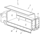
図1は本発明に係るステップ10を貨物自動車1に取り付けた状態を示すものである。この貨物自動車1は、ウイングボディ式の荷台2を備えたウイングボディ車と呼ばれるもので、前記荷台2は、床板3と、該荷台2の前面に設けられたフロントパネル4と、前記荷台2の左右両側面に、外側に向けて起倒自在に設けられたアオリ5と、前記荷台2の後面に設けられたリヤドア6と、前記荷台2の上面に跳ね上げ式に開閉自在なるように設けられたウイングルーフ7とを有し、前記フロントパネル4及び左右のアオリ5の内側面には、荷崩れ防止ベルト(不図示)の金具を取り付けるための金属製の細長いレール8が、横向き即ち水平に取り付けられている。
FIG. 1 shows a state in which a
前記レール8は、図2から明らかなように、断面形状が溝形をしたレールであって、前記左右のアオリ5の内面の上端部近くに、該アオリ5のほぼ全長に亘って延在するように取り付けられている。そして、該レール8には、その幅方向(アオリ5の縦方向)に細長い複数のスロット9が、該レール8の長手方向に一定間隔を保って並列をなすように形成されている。
As is apparent from FIG. 2, the
前記ステップ10は、貨物自動車1のアオリ5に取り付けられた前記荷崩れ防止ベルト取付用レール8を利用して該アオリ5に取り付けるようにしたもので、前記貨物自動車1の荷台2に荷物を積み降ろしするに際し、図1−図3に示すように、前記ウイングルーフ7を開放して前記アオリ5を外側に倒したとき、前記レール8のスロット9に装着して使用される。
In the
前記ステップ10は、図4に示すように、前記スロット9に取り付けるための取付部11と、足場にするための踏台部12とを有している。なお、以下の説明において、前記取付部11がある側をステップ10の後方側とし、該取付部11から前記踏台部12が延出する側をステップ10の前方側とする。
As shown in FIG. 4, the
前記取付部11は、金属からなる矩形のプレート状をした垂直ベース部13に、前記スロット9に挿入して該スロット9に係止させるための縦に細長い複数の取付金具14と、前記レール8又はアオリ5に当接する合成ゴムや合成樹脂等からなる複数の当接体15とを設けたものである。前記金属としては、鉄、ステンレス、アルミニウム合金等が適している。
The
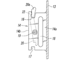
前記取付金具14は、図5及び図6から明らかなように、鉄やステンレスあるいはアルミニウム合金等からなる金属板を略U字形に折曲することにより、中空状に形成されたもので、左右の側壁14a,14aと、該左右の側壁14a,14aの後端部同士を接続する後端壁14bとを有し、2つの前記取付金具14,14が、左右に並行する配置で、前記垂直ベース部13に溶接や螺子止め等の固定手段で一体に固定されている。前記2つの取付金具14,14間の間隔は、隣接する前記スロット9,9間の間隔の整数倍であり、図示した例では、前記取付金具14,14間の間隔がスロット9,9間の間隔の2倍に形成されている。
As apparent from FIGS. 5 and 6, the
前記取付金具14の上端部と下端部との互いに相対する位置には、前記スロット9の上縁部9a及び下縁部9bが嵌合して係止する(図3参照)凹状の第1切欠部16と第2切欠部17とが形成され、上端部側の第1切欠部16の深さは、下端部側の第2切欠部17の深さより深くされている。
図中の符号18は、前記左右の側壁14a,14aに上下方向に形成された肉抜き用の孔であるが、この孔18は必ずしも設ける必要はない。
The
また、前記取付金具14の中空部14c内には、前記左右の側壁14a,14a間に掛け渡された水平の支軸19を中心に該取付金具14の前後方向に回動自在のレバー部材20と、該レバー部材20をその上端部が前記取付金具14の後方側に向けて傾斜するように付勢するばね21とが設けられている。
Further, in the
前記レバー部材20は、ステップ10を前記スロット9に取り付けたとき、当接部22が該スロット9の上縁部9aの下端に当接して該ステップ10が上方へ移動するのを防止し、それによって該ステップ10がアオリ5から脱落するのを防止する役目を果たすもので、このレバー部材20の上端部は、前記ステップ10の着脱時に、該レバー部材20を回動させて前記当接部22をスロット9の上縁部9aの下方位置から逃がすための操作部20aとされ、該操作部20aより下方の位置に、段状をした前記当接部22が形成されている。
When the
前記レバー部材20の上端部即ち前記操作部20aは、前記取付金具14の上端よりも上方に突出し、前記当接部22は、前記取付金具14の上端より下位であるが前記第1切欠部16の底部よりは上位であるような位置に形成されている。
The upper end portion of the
前記ばね21は、弾性針金で形成されたトーションばねであって、前記支軸19を取り巻くように装着され、該ばね21の一端は前記取付金具14の後端壁14bの内面に係止し、該ばね21の他端は前記レバー部材20に係止している。そして、このばね21の作用により前記レバー部材20は、ステップ10がアオリ5に装着されていないとき、図6に鎖線で示すように、前記当接部22の後端部が前記取付金具14の後端壁14bの内面に当接する初期位置を占める。
The
前記踏台部12は、鉄、ステンレス、アルミニウム合金等の金属からなる矩形のプレート状をした水平ベース部23を有し、該水平ベース部23は、前記垂直ベース部13の上端部近くに、基端部を溶接やボルト止めあるいは一体成型等の手段で固定されて横向き且つステップ10の前方に向けて延出し、該水平ベース部23の上面に、滑り止め機能を備えた踏み板24が固定されている。前記水平ベース部23及び踏み板24は、前記取付金具14より上方位置にある。図中の符号25が付された部分は、前記水平ベース部23と垂直ベース部13とが連なる角部に固定された三角形状の補強板である。
The
前記踏み板24は、ゴムや合成樹脂等によって形成されたもので、上面に筋状あるいは点状をした滑り止め用の複数の突起24aが形成され、複数のボルト26で前記水平ベース部23に固定されている。前記ボルト26の頭部は、前記踏み板24から突出していても突出していなくても良いが、それを突出させることにより、滑り止め用として機能させることもできる。
また、前記踏み板24は、例えば、古タイヤなどのゴム製の廃材やプラスチック製の廃材等を素材として形成することができ、このような廃材を利用することにより、資源の有効利用を図ることができると同時に、環境汚染の防止にも役立つことができる。
The
The
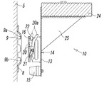
前記ステップ10は、次のようにして前記アオリ5に取り付けられる。先ず、図7に示すように、初期位置(鎖線位置)にある前記レバー部材20の操作部20aを、ばね21の付勢力に抗して指で前記取付金具14の前方側(垂直ベース部13側)に向けて押すことにより、該レバー部材20を、実線で示すように、前記当接部22が第1切欠部16の側面域からステップ10の前方側に完全に外れる待避位置まで回動させる。
The
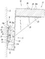
次に、前記レバー部材20を待避位置に保持した状態で、図8に示すように、前記ステップ10の上部をアオリ5側に傾けて、前記取付金具14の上端部後端をレール8のスロット9の内部に挿入し、該スロット9の上縁部9aが前記第1切欠部16の底部に当接する位置までステップ10を持ち上げたあと、図9に示すように、該ステップ10を上下真っ直ぐな姿勢にし、その姿勢で該ステップ10を下げる。そして、図3に示すように、第2切欠部17内に前記スロット9の下縁部9bを嵌合させて該下縁部9bの上端を前記第2切欠部17の底部に当接させ、その状態で前記レバー部材20を解放する。
Next, with the
そうすると、該レバー部材20が、前記ばね21の付勢力によって前記初期位置に向けて復帰することにより、前記レバー部材20の上端の操作部20aと前記第1切欠部16の後端壁16aとの間に前記スロット9の上縁部9aが挟持されると共に、該レバー部材20の当接部22が前記スロット9の上縁部9aの下方に位置する動作位置を占め、該ステップ10の取り付けが完了する。
Then, the
このとき、前記ステップ10には、前記取付金具14より上方位置で該ステップ10の前方に突き出す前記踏台部12の重さによって、前下がり方向の力(モーメント)が作用するが、この力は、前記スロット9の上縁部9a内面に係止する前記第1切欠部16の後端壁16aと、前記レール8の下端部か又はアオリ5に当接する前記当接体15とによって支持されることになる。
At this time, a force (moment) in the forward and downward direction acts on the
このようにして前記ステップ10を前記アオリ5に取り付けることにより、作業者は、このステップ10の踏み板24を足場にして荷台2に簡単に乗り降りすることができる。このとき、前記ステップ10に作用する荷重は、前述したように、前記第1切欠部16の後端壁16aと前記当接体15とによって支持されるが、仮に該当接体15が前記レール8の下端部にもアオリ5に当接しない場合でも、該当接体15の代わりに、前記第2切欠部17の前端壁17aが、前記スロット9の下縁部9b外面に係止することによって前記荷重は支持される。従って、前記当接体15を省略することもできる。
By attaching the
また、前記ステップ10に上向きの外力が作用した場合には、前記レバー部材20の当接部22が前記スロット9の上縁部9aの下端に係止して該ステップ10の上方への移動が防止されるため、該ステップ10がスロット9から外れることがなく、そのため安全性に優れる。
Further, when an upward external force is applied to the
荷物の積み降ろしが終了して前記ステップ10を取り外すときは、該ステップ10を取り付けるときとは逆の手順に従ってその取り外しを行えば良い。取り外したステップ10は、荷台2の適当な場所に収納して搬送することができる。
また、前記ステップ10は、前記レール8が取り付けられている他の貨物自動車にも共通に使用することができる。
When the
Further, the
図示した実施形態では、前記取付金具14が、金属板をU字状に折り曲げた形に形成されているが、該取付金具14は、平板状をしていても良く、平板状をした該取付金具14の側面に、切り起こしによる突起や該側面に取り付けたピン等によって、前記レバー部材20の回動域を区画し、該回動域内で回動するように前記レバー部材20を前記取付金具14に取り付けた構成であっても良い。
In the illustrated embodiment, the mounting
また、前記ステップ10は、前記ウイングボディ車以外の、アオリに荷崩れ防止ベルト取付用のレールが予め取り付けられていない通常の貨物自動車であっても、前記レール8と同様のレールをアオリの内側面の必要な位置に取り付けることにより、該アオリに装着して使用することができる。
In addition, the
図10及び図11は、本発明に係るステップの変形例の要部を示すもので、このステップ10は、当接部22を有する前記レバー部材20を設ける代わりに、第1切欠部16の後端壁16aの一部に、該第1切欠部16の前端壁16b側に向けて、該第1切欠部16の幅を狭める方向に張り出す張出壁16cを形成し、該張出壁16cの上端の段部に前記当接部22を形成したものである。従って、前記張出壁16cの高さは、前記第1切欠部16の深さより低く、前記ステップ10をレール8に取り付けたとき、該張出壁16cがスロット9の上縁部9aより下方に位置するような高さである。
FIGS. 10 and 11 show a main part of a modified example of the step according to the present invention. In this
このようにすれば、前記ステップ10をレール8に取り付けたとき、該ステップ10の前方に突出する前記踏台部12の重さによって該ステップ10は自然と前下がり気味になり、前記張出壁16cの当接部22がスロット9の上縁部9aの下に位置するため、該当接部22によってステップ10の上方への変位が防止される。特に、前記踏台部12が前記取付金具14より上方の位置に設けられているため、ステップ10の前下がり姿勢はより顕著になる。
In this way, when the
なお、図示した実施形態では、前記レバー部材20や第1切欠部16の後端壁16a等に前記当接部22を設け、この当接部22で、該ステップ10が上方に変位してスロット9から外れるのを防止するようにしているが、該ステップ10の重量はかなり大きく、足場としての使用時には更に作業者の体重等が加わるため、少々の外力や振動等が作用してもスロット9から外れるほど上方に変位するおそれは少ない。従って、この点を考慮すると、前述したような当接部22を必ずしも設ける必要はない。即ち、前記レバー部材20や張出壁16c等は省略することもできる。
In the illustrated embodiment, the abutting
また、図示して実施形態では、前記垂直ベース部13及び水平ベース部23が板状をしているが、該垂直ベース部13及び水平ベース部23は、チャンネル材等を組み合わせることによって枠状に形成することもできる。
In the illustrated embodiment, the
1 貨物自動車
2 荷台
5 アオリ
7 ウイングルーフ
9 スロット
10 ステップ
11 取付部
12 踏台部
13 垂直ベース部
14 取付金具
16 第1切欠部
16a 後端壁
16b 前端壁
16c 張出壁
17 第2切欠部
20 レバー部材
20a 操作部
21 ばね
22 当接部
23 水平ベース部
24 踏み板
DESCRIPTION OF SYMBOLS 1
Claims (7)
前記取付部は、前記スロットに挿入して係止させるための複数の取付金具を有し、該取付金具の上端部及び下端部には、前記スロットの上縁部及び下縁部が嵌合して係止する凹状の第1切欠部及び第2切欠部が形成され、上端部側の第1切欠部の深さは下端部側の第2切欠部の深さより深い、
ことを特徴とする貨物自動車用着脱式ステップ。 A detachable step that is used by being attached to a slot provided in a tilt of a loading platform of a lorry vehicle, the step including an attaching portion for attaching to the slot, and a step portion for making a scaffold,
The mounting portion has a plurality of mounting brackets that are inserted into the slot and locked therein, and the upper and lower edges of the slot are fitted to the upper end portion and the lower end portion of the mounting bracket. A concave first notch and a second notch are formed, and the depth of the first notch on the upper end side is deeper than the depth of the second notch on the lower end side,
A detachable step for a truck.
前記踏台部は、前記垂直ベース部から横向きに延びる水平ベース部を有し、該水平ベース部には、滑り止め機能を備えた踏み板が取り付けられている、
ことを特徴とする請求項1に記載の着脱式ステップ。 The mounting portion has a vertical base portion extending vertically, and the two vertical mounting portions are provided so that the two mounting brackets are parallel to each other.
The step part has a horizontal base part extending laterally from the vertical base part, and a step board having a non-slip function is attached to the horizontal base part.
The detachable step according to claim 1.
前記レバー部材には、前記ばねの付勢力に抗して該レバー部材を回動操作するための操作部と、前記当接部とが形成されている、
ことを特徴とする請求項4に記載の着脱式ステップ。 The mounting bracket is provided with a lever member that is rotatable in the front-rear direction of the step, and a spring that biases the lever member so that the upper end side is inclined toward the rear side of the step,
The lever member is formed with an operation portion for rotating the lever member against the biasing force of the spring, and the contact portion.
The detachable step according to claim 4.
Priority Applications (1)
| Application Number | Priority Date | Filing Date | Title |
|---|---|---|---|
| JP2015241302A JP2017105352A (en) | 2015-12-10 | 2015-12-10 | Truck detachable step |
Applications Claiming Priority (1)
| Application Number | Priority Date | Filing Date | Title |
|---|---|---|---|
| JP2015241302A JP2017105352A (en) | 2015-12-10 | 2015-12-10 | Truck detachable step |
Publications (1)
| Publication Number | Publication Date |
|---|---|
| JP2017105352A true JP2017105352A (en) | 2017-06-15 |
Family
ID=59058565
Family Applications (1)
| Application Number | Title | Priority Date | Filing Date |
|---|---|---|---|
| JP2015241302A Pending JP2017105352A (en) | 2015-12-10 | 2015-12-10 | Truck detachable step |
Country Status (1)
| Country | Link |
|---|---|
| JP (1) | JP2017105352A (en) |
Cited By (2)
| Publication number | Priority date | Publication date | Assignee | Title |
|---|---|---|---|---|
| JP2022087394A (en) * | 2020-12-01 | 2022-06-13 | 有限会社 兼子鉄工所 | Rear-panel-fixed step |
| KR102769889B1 (en) * | 2024-07-24 | 2025-02-20 | 주식회사 효경특장 | Removable footrest of wing body truck |
Citations (1)
| Publication number | Priority date | Publication date | Assignee | Title |
|---|---|---|---|---|
| JP2013163467A (en) * | 2012-02-13 | 2013-08-22 | Tatsuo Fujieda | Device for climbing up and down rear deck of truck |
-
2015
- 2015-12-10 JP JP2015241302A patent/JP2017105352A/en active Pending
Patent Citations (1)
| Publication number | Priority date | Publication date | Assignee | Title |
|---|---|---|---|---|
| JP2013163467A (en) * | 2012-02-13 | 2013-08-22 | Tatsuo Fujieda | Device for climbing up and down rear deck of truck |
Cited By (3)
| Publication number | Priority date | Publication date | Assignee | Title |
|---|---|---|---|---|
| JP2022087394A (en) * | 2020-12-01 | 2022-06-13 | 有限会社 兼子鉄工所 | Rear-panel-fixed step |
| JP7566312B2 (en) | 2020-12-01 | 2024-10-15 | 有限会社 兼子鉄工所 | Tilt board fixing step |
| KR102769889B1 (en) * | 2024-07-24 | 2025-02-20 | 주식회사 효경특장 | Removable footrest of wing body truck |
Similar Documents
| Publication | Publication Date | Title |
|---|---|---|
| CA2600671C (en) | Slide out cargo floor | |
| US20090020360A1 (en) | Landing ladder | |
| CN1665712A (en) | Stanchion | |
| WO2015033385A1 (en) | Vehicle deck panel lock device | |
| JP2017105352A (en) | Truck detachable step | |
| JP4838900B2 (en) | Hinge structure of rotating member of cargo transportation vehicle | |
| JP4679961B2 (en) | Sliding device for vehicle seat | |
| JP4556136B2 (en) | Fall prevention tool and its use, and fall prevention fence and its use | |
| JP5421888B2 (en) | Movable cradle for cargo vehicles | |
| JP3166840U (en) | Truck bed structure | |
| JP5534734B2 (en) | Lifting step fixing device | |
| JP2005042507A (en) | Outrigger and outrigger attached body | |
| JP2013163467A (en) | Device for climbing up and down rear deck of truck | |
| KR200425685Y1 (en) | Ladder for up / down with variable installation angle | |
| JP5498057B2 (en) | Lifting step fixing device | |
| RU99399U1 (en) | CROWBAR WITH A BROKEN TYPE PLATFORM (OPTIONS) | |
| JP7453095B2 (en) | Lifting steps and loading platform unit | |
| JP2015123894A (en) | Truck work floor | |
| JP7410067B2 (en) | Locking member installation device | |
| KR20160051958A (en) | Forklift Having Movable Tool Box | |
| JP6146911B2 (en) | Loading jig and automobile | |
| JP2014133604A (en) | Devanning equipment | |
| JP2013132911A (en) | Cargo receiving platform elevating device | |
| JP4111605B2 (en) | Lorry | |
| JP2006142849A (en) | Vehicle loading platform |
Legal Events
| Date | Code | Title | Description |
|---|---|---|---|
| A02 | Decision of refusal |
Free format text: JAPANESE INTERMEDIATE CODE: A02 Effective date: 20170328 |