JP2017109577A - Information display system - Google Patents
Information display system Download PDFInfo
- Publication number
- JP2017109577A JP2017109577A JP2015244778A JP2015244778A JP2017109577A JP 2017109577 A JP2017109577 A JP 2017109577A JP 2015244778 A JP2015244778 A JP 2015244778A JP 2015244778 A JP2015244778 A JP 2015244778A JP 2017109577 A JP2017109577 A JP 2017109577A
- Authority
- JP
- Japan
- Prior art keywords
- display
- display screen
- user
- information
- reflector
- Prior art date
- Legal status (The legal status is an assumption and is not a legal conclusion. Google has not performed a legal analysis and makes no representation as to the accuracy of the status listed.)
- Pending
Links
- 238000001514 detection method Methods 0.000 claims abstract description 63
- 230000007246 mechanism Effects 0.000 claims description 11
- 230000000007 visual effect Effects 0.000 claims description 11
- 230000002441 reversible effect Effects 0.000 claims description 3
- 238000004381 surface treatment Methods 0.000 claims description 3
- 238000011179 visual inspection Methods 0.000 abstract 2
- 238000000034 method Methods 0.000 description 12
- 230000003287 optical effect Effects 0.000 description 12
- 230000000694 effects Effects 0.000 description 9
- 239000004973 liquid crystal related substance Substances 0.000 description 8
- 230000008859 change Effects 0.000 description 7
- 238000010586 diagram Methods 0.000 description 7
- 230000006870 function Effects 0.000 description 7
- 230000008569 process Effects 0.000 description 7
- 238000003745 diagnosis Methods 0.000 description 6
- 230000004397 blinking Effects 0.000 description 5
- 210000001747 pupil Anatomy 0.000 description 5
- 239000000446 fuel Substances 0.000 description 4
- 238000009434 installation Methods 0.000 description 4
- 239000011159 matrix material Substances 0.000 description 4
- 239000000758 substrate Substances 0.000 description 4
- 230000002238 attenuated effect Effects 0.000 description 3
- 238000005286 illumination Methods 0.000 description 3
- 230000002829 reductive effect Effects 0.000 description 3
- 230000010365 information processing Effects 0.000 description 2
- 230000001681 protective effect Effects 0.000 description 2
- 230000009467 reduction Effects 0.000 description 2
- 241000282326 Felis catus Species 0.000 description 1
- 125000002066 L-histidyl group Chemical group [H]N1C([H])=NC(C([H])([H])[C@](C(=O)[*])([H])N([H])[H])=C1[H] 0.000 description 1
- 241001465754 Metazoa Species 0.000 description 1
- NIXOWILDQLNWCW-UHFFFAOYSA-N acrylic acid group Chemical group C(C=C)(=O)O NIXOWILDQLNWCW-UHFFFAOYSA-N 0.000 description 1
- 238000005452 bending Methods 0.000 description 1
- 239000003638 chemical reducing agent Substances 0.000 description 1
- 235000019506 cigar Nutrition 0.000 description 1
- 238000004140 cleaning Methods 0.000 description 1
- 239000011248 coating agent Substances 0.000 description 1
- 238000000576 coating method Methods 0.000 description 1
- 230000007423 decrease Effects 0.000 description 1
- 238000005401 electroluminescence Methods 0.000 description 1
- 239000011521 glass Substances 0.000 description 1
- 210000003128 head Anatomy 0.000 description 1
- 230000007257 malfunction Effects 0.000 description 1
- 239000000463 material Substances 0.000 description 1
- 230000000414 obstructive effect Effects 0.000 description 1
- 229920003023 plastic Polymers 0.000 description 1
- 229920000515 polycarbonate Polymers 0.000 description 1
- 239000004417 polycarbonate Substances 0.000 description 1
- 229920000728 polyester Polymers 0.000 description 1
- 239000011347 resin Substances 0.000 description 1
- 229920005989 resin Polymers 0.000 description 1
- 230000000630 rising effect Effects 0.000 description 1
Images









Landscapes
- Instrument Panels (AREA)
- Controls And Circuits For Display Device (AREA)
- Devices For Indicating Variable Information By Combining Individual Elements (AREA)
- Fittings On The Vehicle Exterior For Carrying Loads, And Devices For Holding Or Mounting Articles (AREA)
Abstract
Description
本発明は、情報表示システムに関するものである。 The present invention relates to an information display system.
従来から情報表示システムとして例えば、自動車や自転車のような車両に搭載するナビゲーション装置や自動車に搭載するマイクロ波検出器(レーダー探知機)のように運転に関する情報を取得して表示画面にその内容を表示させるようにした電子機器類、あるいは地デジTV、CD、DVD等の視覚的な情報内容を表示画面に表示させるようにした車両用のオーディオ装置のような電子機器類が挙げられる。
これらのような従来の電子機器の一例として特許文献1及び2を挙げる。特許文献1に開示される電子機器類は自動車の車内のダッシュボード上に配置されるヘッドアップディスプレイ(HUD)である。このHUDは特許文献1の図1〜5に示すように透明樹脂製のコンバイナ3を備えケース1内に配設された表示器2から情報を含んだ映像光をコンバイナ3に投射して間接的にユーザーに目視させる構成である。
しかし、特許文献1のようなHUDではユーザーにコンバイナ3を介して間接的に表示器2を目視させることになるため、夜やあるいは昼間でも雨天や曇天の比較的暗い状態であればコンバイナ3に投影される映像光を十分目視できるものの、周囲の光量が多くなる天気のよい昼間ではコンバイナ3に投影される映像光が外光に対して相対的に十分ではない場合もあり表示内容が見にくくなってしまう可能性がある。
Conventionally, as information display systems, for example, navigation information mounted on vehicles such as automobiles and bicycles and microwave detectors (radar detectors) mounted on automobiles are used to acquire information on driving and display the contents on the display screen. Examples include electronic devices that are displayed, or electronic devices such as an audio device for a vehicle that displays visual information such as terrestrial digital TV, CD, and DVD on a display screen.
However, in HUD like
一方、特許文献2には例えばその図6に示すように、自動車の車内のダッシュボード上に配置される表示画面602を備えたディスプレイ601が開示されている。この特許文献2のようなユーザーが直接目視する表示部を備えた情報表示システムであれば表示部を直接目視することができるので天気のよい昼間であっても上記特許文献1のHUDのように見にくいということはない。
しかしながら、特許文献2のような表示部を直接目視する電子機器類では、一般的に天気のよい昼間はHUDに比べると見やすいものの、上記のように夜や雨天等の暗い状態ではかえって明るすぎてまぶしく感じてしまうことになる。
そのため、特許文献1のように間接的に表示画面を目視する表示画面と特許文献2のように直接的に表示画面を目視する表示画面の両方を備える電子機器類を設置して状況に応じていずれかの表示画面をユーザが見るように構成するということも考えられるが、両方の画面を備えるようにした場合には全体が大型化するためその設置場所によってはユーザーの視界を妨げる場合がある。また、異なる表示画面を備えるようにすることは高コスト化を将来する等の問題がある。
本発明は上記問題を解消するためになされたものであり、その目的は、1つの表示画面でユーザーが間接的に目視したり直接的に目視したりすることのできる表示画面を備えた情報表示システムを提供することにある。
On the other hand, for example, as shown in FIG. 6,
However, in electronic devices that directly observe the display unit as in
Therefore, according to the situation, electronic devices including both a display screen for indirectly viewing the display screen as in
The present invention has been made to solve the above problems, and its purpose is to display information with a display screen that can be viewed indirectly or directly by a user on a single display screen. To provide a system.
上記目的を達成するために、手段1として表示画面を反射体に反射させて表示内容をユーザーに間接的に目視させる第1の表示態様と、表示画面の表示内容をユーザーに直接的に目視させる第2の表示態様とを有することがよい。
このような構成であれば、ユーザーは周囲の明るさの状況に応じて見やすい表示態様で表示画面に表示される情報を認識することが可能となる。
人の目は周囲が暗ければ瞳孔が開いてより多くの光を取り込むようにして光量が少ない場合でも物を見ることができるような仕組みになっている。一方で、明るい昼間のような光が多い場合には瞳孔が縮んで取り込む光を抑制する。表示画面の明るさが同じであれば直接的に目視する場合よりも間接的に目視する場合の方が相対的に明るさは減衰する。そのため、瞳孔が開いている「暗い」場合には表示内容をユーザーに間接的に目視させ、瞳孔が縮んでいる「明るい」場合に表示内容をユーザーに直接的に目視させることがユーザーにとっての見やすさにつながる。
表示画面は例えば有機ELディスプレイや液晶ディスプレイ(LiquidCrystalDisplay:LCD)のような、自発光またはバックライト光によって光を発するドットマトリクスディスプレイとするとよい。一般的にHUDは反射で光量が下がることと昼間に視認できるように高輝度な表示方法が必要とされることが多い。しかし、手段1の構成によれば、表示画面を反射体に反射させて表示内容をユーザーに間接的に目視させる第1の表示態様は例えばヘッドライトが必要となるような周囲が暗くなる状況、例えば夜間等に限定すればよいためそれほど大きな輝度が必要ではなく、一方で、表示画面の表示内容をユーザーに直接的に目視させる第2の表示態様は例えば昼間など周囲が明るい状況をとることができる。そして、安価な汎用液晶等のドットマトリクスディスプレイを使用することができ低コスト化に寄与する。また、直接見ても高解像度できれいな表示を保つことができる。
また、「周囲の明るさ」は周囲の環境によって左右され、例えば、日中の日の差し込む室内であれば夜間に比べて当然かなり明るいといえる。しかし、日中であっても雨天や曇天であれば日の差し込んでいるような際の光量に比べてかなり少なく暗く感じる。また、夜間であっても照明下、例えば車両を考えた場合にトンネルの中や対向車のヘッドライトに照らされた状態は明るいといえる。そのため、昼間であっても第1の表示態様を選択する場合もあり、逆に夜間であっても第2の表示態様を選択する場合もある。
ここに、「反射体」とは、表示画面から投射した映像光をユーザに目視可能に反射させることができるものであればよく、ミラー体であっても、透明体であってもよい。透明体であっても表示画面から投射された映像光を反射しなければユーザーが目視できないため透明体はハーフミラー、つまりコンバイナである。反射された虚像は二次元的な像であっても三次元的なホログラムであってもよい。
「反射体に反射させる」場合には表示画面を直接反射体に反射させてもよく、途中で光を光学系、例えばミラーに反射させたりレンズを通したりしてから反射体に到達させるようにしてもよい。
In order to achieve the above object, as a
With such a configuration, the user can recognize information displayed on the display screen in an easy-to-view display mode according to the surrounding brightness situation.
When the human eye is dark, the pupil opens so that more light can be taken in so that the object can be seen even when the amount of light is small. On the other hand, when there is a lot of light such as bright daytime, the pupil contracts and suppresses the captured light. If the brightness of the display screen is the same, the brightness is relatively attenuated when viewing indirectly rather than when viewing directly. Therefore, it is easy for the user to see the display contents indirectly when the pupil is open “dark”, and to allow the user to visually check the display contents when the pupil is contracted “bright”. Leads to
The display screen may be a dot matrix display that emits light by self-light emission or backlight, such as an organic EL display or a liquid crystal display (LCD). In general, the HUD often requires a display method with high brightness so that the amount of light decreases due to reflection and can be visually recognized in the daytime. However, according to the configuration of the
The “ambient brightness” depends on the surrounding environment. For example, in a room where the daytime is inserted, it can be said that it is naturally much brighter than at night. However, even in the daytime, if it is raining or cloudy, it feels much darker than the amount of light when the sun is entering. Even at night, it can be said that the state illuminated by the headlights of the tunnel or the oncoming vehicle under illumination, for example, when considering a vehicle, is bright. For this reason, the first display mode may be selected even during daytime, and the second display mode may be selected even during nighttime.
Here, the “reflector” may be any mirror that can visually reflect the image light projected from the display screen to the user, and may be a mirror body or a transparent body. Even if it is a transparent body, the transparent body is a half mirror, that is, a combiner, because it cannot be viewed by the user unless the image light projected from the display screen is reflected. The reflected virtual image may be a two-dimensional image or a three-dimensional hologram.
In the case of “reflecting on a reflector”, the display screen may be reflected directly on the reflector, and the light is reflected on the optical system, for example, a mirror or a lens, before reaching the reflector. May be.
また、手段2として、前記第1の表示態様と前記第2の表示態様のいずれかを選択可能とすることがよい。
これによってユーザーが見やすいと感じる第1又は第2のいずれかの表示態様を選択して情報を目視させることが可能となる。例えば、昼間でも周囲が暗いと感じる場合にはユーザーは間接的に表示内容を目視した方が見やすいと考えて第1の表示態様を選択することができる。また、逆に夜間でも十分な照明下であれば直接的に表示内容を目視した方が見やすいと考えて第2の表示態様を選択することができる。
選択はユーザーの主観によってユーザー自ら選択してもよいが、選択するために前記第1の表示態様と前記第2の表示態様との間を適宜変更させる選択手段又は変更手段があるとよい。ユーザー自ら選択する際には第1の表示態様と第2の表示態様のいずれかのモードを選択できる選択手段を有することがよい。選択手段としては例えば切り換えスイッチやリモコンのような操作手段がよい。選択手段又は変更手段としては後述するように例えば制御手段によって自動的に行うようにすることがよい。
また、手段3として、前記第1の表示態様における前記反射体に対するユーザーの自らの視線方向と前記第2の表示態様における前記表示画面に対するユーザーの視線方向は同じ方向であることがよい。
これによって、ユーザーは第1の表示態様でも第2の表示態様でも視線を移動させることなく表示画面を見続けることが可能となる。ここに「視線方向が同じ」とはある一点方向だけとしてもよいが、視線方向を含む視野内に収まる幅をもつ概念として構成してもよい。
Further, as the
As a result, it is possible to select either the first or second display mode that the user feels easy to see and to make the information visible. For example, when the user feels that the surroundings are dark even in the daytime, the user can select the first display mode on the assumption that it is easier to see the display content indirectly. On the contrary, the second display mode can be selected on the assumption that it is easier to see the display contents directly if it is under sufficient illumination even at night.
Selection may be made by the user himself or herself depending on the subjectivity of the user, but there may be selection means or changing means for appropriately changing between the first display mode and the second display mode for selection. When the user himself selects, it is preferable to have a selection means capable of selecting either the first display mode or the second display mode. As the selection means, for example, an operation means such as a changeover switch or a remote control is preferable. The selection means or the change means may be automatically performed by a control means, for example, as will be described later.
Moreover, as the means 3, it is preferable that the user's own gaze direction with respect to the reflector in the first display mode and the user's gaze direction with respect to the display screen in the second display mode are the same direction.
As a result, the user can continue to watch the display screen without moving the line of sight in either the first display mode or the second display mode. Here, “the direction of the line of sight is the same” may be a single point direction, but may be configured as a concept having a width that fits within the visual field including the line of sight direction.
また、手段4として、制御手段によって前記第1の表示態様では前記表示画面に反転画像を表示させ、前記第2の表示態様では前記表示画面に反転していない通常画像を表示させるように制御することがよい。
このように、反射体に映像光を反射させてユーザーに間接的に目視させるという第1の表示態様の際には映像光は反射体に反射して鏡像反転して目視されるため、表示画面には逆に裏向きに反転した画像を表示させることで、例えば数字や文字のような対称性のない態様で表示される画像をユーザーに本来読み取ることのできる正しい画像として目視させることができる。
一方、第2の表示態様の際にはユーザーは直接的に表示画面を目視するため、表示画面には正しい画像が表示されることとなる。
Further, as the means 4, the control means controls to display an inverted image on the display screen in the first display mode and to display a non-inverted normal image on the display screen in the second display mode. It is good.
In this way, in the first display mode in which the image light is reflected on the reflector and indirectly viewed by the user, the image light is reflected on the reflector and viewed in a mirror image. On the other hand, by displaying an image reversed in the reverse direction, for example, an image displayed in a non-symmetrical manner such as a number or a character can be visually recognized as a correct image that can be read by the user.
On the other hand, since the user directly looks at the display screen in the second display mode, a correct image is displayed on the display screen.
また、手段5として、前記制御手段は前記第1の表示態様で前記反射体を目視するユーザーの視野上方側が表示情報の上方側となるように前記表示画面に反転画像を表示させることがよい。
このように反射体に反射させた画像がユーザーの視野上方側が表示情報の上方側となることで、例えば数字や文字のような上下方向のある画像がユーザーにとって読みやすくなる。第2の表示態様の直接表示画面を目視する場合も同様に画像がユーザーの視野上方側が表示情報の上方側となることがよい。
Further, as the means 5, the control means may display an inverted image on the display screen so that the upper side of the visual field of the user viewing the reflector in the first display mode is the upper side of the display information.
As described above, in the image reflected by the reflector, the upper side of the visual field of the user is the upper side of the display information, so that an image having a vertical direction such as a number or a character becomes easy to read for the user. Similarly, when viewing the direct display screen of the second display mode, it is preferable that the upper side of the visual field of the user is the upper side of the display information.
また、手段6として、前記第1の表示態様においてユーザーに目視される表示内容のデザインを前記第2の表示態様においてユーザーに目視される表示内容のデザインとは異なるようにすることがよい。
これによって表示画面をユーザーに間接的に目視させる場合と直接目視させる場合でそれぞれの目視条件に応じたデザインの画像とすることができる。例えば、ユーザーまでの距離に応じて遠い方を相対的に大きな文字の画像としてもよい。また、表示画面を反射体に反射させて表示内容をユーザーに間接的に目視させる場合では、例えば反射体において画像が反射体の厚みによって表裏で反射して二重像として見えてしまうかもしれず、その場合には余り細かなデザインではないほうがよく、ざっくりした例えば大きな文字や記号で見せるようにしてもよい。一方、ユーザーに直接的に表示画面を目視させる場合には特にそのような必要はないため、同じ文字や数字を表示させる場合には相対的に第1の表示態様よりも第2の表示態様で小さく表示させてもよい。
尚、「デザイン」とは例えば数字や文字のような対称性のない態様で表示される画像においては正しい画像と反転画像は同じデザインと考える。
Further, as the means 6, it is preferable that the design of the display content viewed by the user in the first display mode is different from the design of the display content viewed by the user in the second display mode.
As a result, it is possible to obtain an image having a design according to each viewing condition when the display screen is indirectly viewed by the user and when the display screen is directly viewed. For example, a relatively large character image may be used according to the distance to the user. In addition, when the display screen is reflected on the reflector and the display content is indirectly viewed by the user, for example, the image on the reflector may be reflected on the front and back depending on the thickness of the reflector and appear as a double image. In that case, it is better that the design is not too fine, and it may be shown roughly with large letters and symbols, for example. On the other hand, since it is not particularly necessary when the user directly looks at the display screen, the second display mode is relatively more than the first display mode when displaying the same characters and numbers. You may display small.
Note that “design” means that the correct image and the reverse image are the same design in an image displayed in a non-symmetrical manner such as numbers and letters.
また、手段7として、前記第1の表示態様の際にユーザーに対して前記第2の表示態様の方がより見やすい旨の報知をし、前記第2の表示態様の際にユーザーに対して前記第1の表示態様の方がより見やすい旨の報知をする報知手段を設けることがよい。
これによって、ユーザーは例えば現在間接的に表示内容を目視している場合(第1の表示態様の場合)に周囲の明るさが変化することで第2の表示態様がより見やすいと報知されてより見やすい第1の表示態様を自ら選択することが可能となる。その場合には、例えば切り換えスイッチやリモートコントロール(リモコン)等の操作手段を操作して表示態様を変更するようにすることがよい。
このような報知手段として、例えばユーザに対してスピーカからの音声のような聴覚的な手段でも、あるいは表示画面上での視覚的な手段でもよい。
Further, as means 7, the user is notified that the second display mode is easier to see during the first display mode, and the user is notified that the second display mode is easier to see. It is preferable to provide notifying means for notifying that the first display mode is easier to see.
As a result, for example, when the user is currently viewing the display content indirectly (in the case of the first display mode), it is notified that the second display mode is easier to see by changing the ambient brightness. The first display mode that is easy to see can be selected by itself. In this case, it is preferable to change the display mode by operating an operation means such as a changeover switch or a remote control (remote control).
Such notification means may be auditory means such as sound from a speaker for the user or visual means on the display screen.
また、手段8として、前記表示画面は表示内容をユーザーに間接的に目視させる第1の位置と表示内容をユーザーに直接的に目視させる第2の位置との間を移動可能とすることがよい。
これによって、表示画面を第1の位置と第2の位置の間で動かすだけでユーザーに表示画面の間接的な目視(つまり第1の表示態様)と直接的な目視(つまり第2の表示態様)のいずれかが選択的に可能となる。
また、手段9として、前記制御手段は前記表示画面を移動させるための移動機構を制御して前記表示画面を前記第1の位置又は前記第2の位置に配置させるようにすることがよい。
これによってユーザーが自ら手で動かさなくとも制御手段が移動機構を制御して自動的に表示画面を第1の位置又は第2の位置に配置させるため、ユーザー自ら動かす手間が省けて便利である。もちろん、ユーザーが自ら手で表示画面を動かすような構成としてもよい。
Further, as the
As a result, the user only indirectly moves the display screen between the first position and the second position (ie, the first display mode) and directly views the display screen (that is, the second display mode). ) Is selectively possible.
Further, as the
Thereby, even if the user does not move it by hand, the control means controls the moving mechanism and automatically arranges the display screen at the first position or the second position. Of course, the user may move the display screen by hand.
また、手段10として、前記制御手段は光検出手段の検出値に基づいて前記移動機構の駆動動作を制御して前記表示画面を前記第1の位置又は前記第2の位置のいずれかに移動させるようにすることがよい。
制御手段は光検出手段の検出値、つまり明るさのしきい値を決めて、その値よりも明るいか暗いかによって移動機構を駆動させて表示画面を第1の位置又は第2の位置に配置させるようにした。これによって、ユーザーは明るさによって第1の表示態様と第2の表示態様のいずれかユーザにとってより見やすい位置において情報を目視することがかのうとなる。例えば、夜間暗い場合に表示画面を反射体に反射させて表示内容をユーザーに間接的に目視させる第1の表示態様とすることがよい場合には制御手段は表示画面が第2の位置にある場合には第1の位置に移動させることができる(この場合に表示画面が第2の位置にある場合には移動させない)。
また、手段11として、前記制御手段は位置検出手段からの位置情報に基づいて前記移動機構の駆動動作を制御して前記表示画面を前記第1の位置又は前記第2の位置のいずれかに移動させるようにすることがよい。
制御手段は位置検出手段からの位置情報に基づいてその検出した位置情報(例えば緯度データ及び経度データ)を取得することができる。その位置情報と現在時間から現在その位置がどのような光度状態、例えば明るい昼間なのか夜間なのかを判断することができるため、明るさによってユーザにより好適となる第1の位置又は第2の位置に表示画面を移動させることができる。現在時間を計測する手段は位置検出手段にあっても制御手段にあってもよい。位置検出手段としては例えばGPS(GrobalPositioningSystem)がよい。
Further, as the
The control means determines a detection value of the light detection means, that is, a threshold value of brightness, and drives the moving mechanism depending on whether it is brighter or darker than that value and arranges the display screen at the first position or the second position. I tried to make it. This makes it possible for the user to visually observe information at a position that is more easily viewable by the user in either the first display mode or the second display mode. For example, when it is preferable to have the first display mode in which the display screen is reflected by a reflector so that the display contents can be indirectly viewed by the user when it is dark at night, the control means has the display screen in the second position. In this case, it can be moved to the first position (in this case, it is not moved when the display screen is at the second position).
Further, as the
The control means can acquire the detected position information (eg, latitude data and longitude data) based on the position information from the position detection means. The first position or the second position that is more suitable for the user depending on the brightness, because it is possible to determine from the position information and the current time what light intensity state the current position is, for example, bright daytime or nighttime. The display screen can be moved to. The means for measuring the current time may be in the position detection means or the control means. As the position detecting means, for example, GPS (Grobal Positioning System) is preferable.
また、手段12として、前記光検出手段と前記位置検出手段の両方を備える場合において、夜間においては前記制御手段は位置検出手段からの位置情報に基づいて前記移動機構の駆動動作を制御して前記表示画面を前記第1の位置又は前記第2の位置のいずれかに移動させるようにすることがよい。
例えば、夜間であれば本来は暗いため光検出手段ならその検出値から「暗い」という判断で制御手段が移動機構の駆動動作を制御するはずであるが、かえって夜間であるため何らかの強い外光、例えば、システムを車両に搭載している場合に一時的な対抗車の強烈なヘッドライトの光を浴びることをもって「明るい」と判断してしまう可能性もある。そのような一時的な明るさで表示態様を変更することはユーザーに戸惑いを与えてしまう。そのため、このように光検出手段と位置検出手段の両方を備えている場合には制御手段は位置検出手段からの検出値を優先して制御することで夜間に適したユーザーが戸惑うことのない表示態様が可能となる。
Further, in the case where both the light detection means and the position detection means are provided as the means 12, the control means controls the driving operation of the moving mechanism based on the position information from the position detection means at night. The display screen may be moved to either the first position or the second position.
For example, if it is nighttime, it is originally dark, so if it is a light detection means, the control means should control the driving operation of the moving mechanism by judging that it is `` dark '', but instead it is nighttime, so some strong external light, For example, when the system is mounted on a vehicle, it may be judged as “bright” when exposed to intense headlights of a temporary opponent vehicle. Changing the display mode with such temporary brightness causes confusion to the user. For this reason, when both the light detection means and the position detection means are provided in this way, the control means gives priority to the detection value from the position detection means so that the user suitable for the night will not be confused. Embodiments are possible.
また、手段13として、前記表示画面は筐体の上方位置で倒伏することで前記第1の位置に配置され、前記第1の位置から起立することで前記第2の位置に配置されるようにすることがよい。
このように表示画面が起立することでユーザーは表示画面が直視しやすくなり、また、倒伏することによってユーザーが反射体を目視する妨げとならないこととなる。
また、手段14として、前記反射体はユーザーに対して起立状態の前記表示画面の位置よりも遠い位置にユーザーに対面するように配置され、前記表示画面は起立状態から前記反射体方向に向かって倒伏するようにすることがよい。
このように構成すると、ユーザーにとっては起立状態においてユーザー方向に向いた表示画面が倒伏することで一旦隠れ、代わって表示画面の映像光の虚像が反射体に反射されて現れる特徴的な演出がされることとなり、ユーザーにとっては面白く感じられ、表示態様の切り替えがすばやく行われることからユーザーにとって表示態様の切り替えのストレスがあまり感じられずにすむ。
Further, as the
As the display screen stands up in this manner, the user can easily view the display screen directly, and the user cannot see the reflector when he / she falls down.
Further, as the
When configured in this way, the display screen facing the user in a standing state is temporarily hidden for the user and then hidden, and instead, a virtual image of the image light on the display screen is reflected by the reflector, and a characteristic effect is produced. Therefore, it feels interesting to the user and the display mode is quickly switched, so that the stress of switching the display mode is less felt for the user.
また、手段15として、前記筐体は保持手段によって取り付け面に対して任意の仰俯角度で保持されることがよい。
このように筐体の仰俯角度が任意に変更できるのであれば、表示画面の第1の位置と第2の位置が例え固定的で変更できないとしても、筐体の角度自体を変更することで表示画面の第1の位置や第2の位置のユーザーに対する向きを変更することができ、ユーザーの視線方向に合わせたセッティングが可能となる。
また、手段16として、前記筐体は保持手段によって任意の回動位置で保持されることがよい。
ユーザーを中心とした周囲のどの位置に筐体を配設しても表示画面をユーザー側に向けることが可能となるため、筐体を設置する位置の選択の裕度が向上する。
また、手段17として、前記反射体は前記筐体に対する取り付け角度が変更可能とされていることがよい。
これによって第1の表示態様において表示画面を反射体に反射させて表示内容をユーザーに間接的に目視させる際に、反射体の取り付け角度をユーザーの視線に応じた好適な角度とすることができる。
Further, as the
If the elevation angle of the housing can be arbitrarily changed in this way, even if the first position and the second position of the display screen are fixed and cannot be changed, the angle of the housing itself can be changed. The orientation of the first position and the second position of the display screen with respect to the user can be changed, and setting according to the user's line-of-sight direction is possible.
Further, as the
Since the display screen can be directed to the user regardless of the position around the user, the display screen can be directed to the user side.
Further, as the
Accordingly, when the display screen is reflected by the reflector in the first display mode and the display content is indirectly viewed by the user, the attachment angle of the reflector can be set to a suitable angle corresponding to the user's line of sight. .
また、手段18として、前記反射体は前記筐体に対し着脱可能であることがよい。
例えば反射体が邪魔な場合や破損して交換する場合に有利である。更に、ユーザーが第2の表示態様、つまり表示画面を直接的に目視するという使用方法だけを選択する場合に反射体は不要であるため取り外しておくことが可能である。
また、手段19として、前記反射体は透明であることがよい。
このような反射体であるとあたかも反射体に反射させられた表示内容の周囲が透明になるので表示内容があたかも宙に浮かぶように表示されることとなり意匠的な効果が大きい。特に上記手段14のようにユーザーからみて前後に重複して表示画面と反射体が配置されるような配置状体では反射体が透明であると表示画面の背景が暗くなりすぎることがなく、ユーザーが表示画面を目視した際にまぶしく感じてしまうことがない。
Moreover, as the
For example, it is advantageous when the reflector is obstructive or is damaged and replaced. Further, when the user selects only the second display mode, that is, the usage method of directly viewing the display screen, the reflector is unnecessary and can be removed.
Further, as the
With such a reflector, the surroundings of the display contents reflected by the reflector become transparent, so that the display contents are displayed as if they are floating in the air, and the design effect is great. In particular, in the arrangement in which the display screen and the reflector are arranged in front and rear overlappingly as seen from the user as in the above-described
また、手段20として、前記反射体の端面は粗面処理がなされ、前記端面に面して配置された発光手段によって前記端面が乱反射するようにすることがよい。
これによって発光手段から反射体に入射した光が反射体の端面位置で乱反射して光るため目立たせることができ、意匠的な効果も大きくなるため、ユーザーが使用することにおいて興趣が盛り上がることとなる。この際に発光手段が配置される位置は反射体の内部に光を効率的に侵入させるために粗面処理をしないことがよい。また、制御手段によってなんらかのイベントが発生することに基づいて発光手段を発光させることがよい。イベントとは、例えば車両走行中にレーダー探知装置がGPS警報、レーダー波警報、無線警報等の報知対象を検出したような場合や、0分ちょうどの各時刻であると判断した場合、前もって入力しておいたユーザーの誕生日等報知することに意味がありユーザーに報知することがよい場合である。
また、手段21として、前記反射体は反射させた表示内容を拡大して表示する凹面部を有することがよい。
これによって反射体は反射させた表示内容を拡大することができ、反射体の反射面の面積を大きくしなくともユーザーが表示画面を直接目視する場合に比べて拡大された大きな画面情報を目視することが可能となる。
また、手段22として、前記反射体として表示内容を拡大して表示する凹面部を有する第1の反射体と、拡大しない平面部を有する第2の反射体の両方を備え、いずれかを選択的に使用可能であることがよい。
これによって、第1の表示態様においてユーザーは表示内容を拡大して表示するパターンと通常の拡大しないパターンを選択することができる。
Further, as the
As a result, the light incident on the reflector from the light emitting means is diffused and radiated at the end face position of the reflector, so that it can be conspicuous, and the design effect is also increased, so that the user's use will be exciting. . In this case, it is preferable that the surface where the light emitting means is disposed is not roughened in order to allow light to enter the reflector efficiently. Further, it is preferable to cause the light emitting means to emit light based on the occurrence of some event by the control means. An event is input in advance when, for example, the radar detection device detects an alarm target such as a GPS alarm, radar wave alarm, or radio alarm while the vehicle is running, or when it is determined that each time is exactly 0 minutes. This is a case where it is meaningful to notify the user's birthday, etc.
Moreover, as the
This allows the reflector to magnify the reflected display content, and allows the user to view larger screen information that is larger than when the user looks directly at the display screen without increasing the reflective surface area of the reflector. It becomes possible.
Further, the
As a result, in the first display mode, the user can select a pattern in which the display content is enlarged and a normal pattern that is not enlarged.
また、手段23として、前記第1の表示態様における前記表示画面の光度を前記第2の表示態様における前記表示画面の光度よりも大きくすることがよい。
上記のように表示画面の明るさが同じであれば、これを直接的に目視する場合よりも間接的に目視する場合の方が相対的に明るさは減衰する。そのため、直視する際にはちょうどよい明るさであっても、間接視する際には暗く感じる場合もある。そのため、このように構成することで、第1の表示態様において表示画面を反射体に反射させて表示内容をユーザーに間接的に目視させる際の光量不足を補填することができる。
Further, as the
If the brightness of the display screen is the same as described above, the brightness is relatively attenuated when the screen is viewed indirectly rather than when the screen is viewed directly. Therefore, even if it is just right when looking directly, it may feel dark when looking indirectly. Therefore, by configuring in this way, it is possible to compensate for a shortage of light when the display screen is reflected by the reflector in the first display mode and the display content is indirectly viewed by the user.
また、手段24として、前記筐体は車両に搭載され、前記制御手段は車両の駆動源が停止している際に、前記表示画面が前記第2の位置にある場合には前記表示画面を前記第1の位置に移動させて前記表示画面に反転していない通常画像を表示させるとともに、前記表示画面が前記第2の位置にある場合に前記表示画面を移動させずにそのまま前記表示画面に反転していない通常画像を表示させるように制御することがよい。
車両の例えばダッシュボード上に情報表示システムを搭載し、その車両の駆動源が停止している場合に、このように構成することで、外部から第2の位置にある表示画面の画像を直接目視させることができる。設置場所がダッシュボード上であればダッシュボードに対して倒伏させた状態が外部の人物がウィンドウを透過して表示画面の画像を目視するのにはよい。反転していない通常画像は車両の運転とは関係のない内容の画像であることがよい。例えば、第三者への警告となる標語や装飾用アニメーションや会社の宣伝広告のような運転に関する情報ではない停車中の車両内をのぞき込む第三者へのメッセージ情報とするのがよい。つまり、一種の携帯電話やパソコン画面の待ち受け画面のように表示画面14を使用することがよい。
Further, as the
When an information display system is mounted on, for example, a dashboard of a vehicle and the drive source of the vehicle is stopped, this configuration allows direct visual observation of the image on the display screen at the second position from the outside. Can be made. If the installation location is on the dashboard, the state of lying on the dashboard is good for an external person to see the image on the display screen through the window. The normal image that is not inverted may be an image that has no relation to the driving of the vehicle. For example, it may be message information to a third party looking into the stopped vehicle that is not information relating to driving such as a slogan, a decorative animation, or a company advertisement that is a warning to a third party. That is, it is preferable to use the
また、手段25として、前記制御手段は前記第1の表示態様及び前記第2の表示態様ではない場合に音声で車両走行における情報を報知するようにすることがよい。
これによってユーザは表示画面を直接、間接を問わず目視しなくとも車両走行における情報を知ることができる。道路交通情報のような外部情報のみならず、自車の速度情報や燃費情報のような内部情報も含む。
また、手段26として、前記表示画面に表示させる表示内容には車両走行における外部情報を含むことがよい。
表示画面には外部情報とは例えば道路交通情報等が挙げられる。そして、表示画面に自車の速度情報や燃費情報のような内部情報や、オーディオ装置として地デジTV、DVD等の情報を切り換えて、あるいは同時に表示させるようにしてもよい。
Further, as the
As a result, the user can know information on vehicle travel without directly or indirectly viewing the display screen. This includes not only external information such as road traffic information but also internal information such as speed information and fuel consumption information of the vehicle.
Moreover, as the
The display screen includes external information such as road traffic information. Then, internal information such as speed information and fuel consumption information of the own vehicle or information such as terrestrial digital TV and DVD as an audio device may be switched or displayed on the display screen at the same time.
本発明によれば、ユーザーの状況に応じた表示画面の間接的な目視と直接的な目視が1つの表示画面だけで可能となる。 According to the present invention, indirect viewing and direct viewing of a display screen according to a user's situation are possible with only one display screen.
以下、本発明の情報表示システムを具体化した電子機器であるレーダー探知装置10の実施の形態を図面に基づいて説明する。
(実施の形態1)
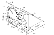
図1〜図4に示すように、本実施の形態1の車両用のレーダー探知装置10は扁平な略直方体形状に構成された筐体としての本体ケース11を備えている。本体ケース11の後端上面側は斜めにカット状に形成された斜壁部11aとされている。
本体ケース11の天板11b側には液晶ディスプレイ(LiquidCrystalDisplay:LCD)モジュールからなる表示器13が配設されている。表示器13(つまりLCDモジュール)は液晶層、基板、カラーフィルター等からなる液晶部とバックライト部と駆動回路と電源回路等から構成された電子機器であり視覚表示装置である。表示器13は平面かつ薄型の長方形形状の外形とされ、その前面側が表示画面14とされている。表示器13の前後幅は本体ケース11の前後幅よりも若干短く、左右幅は本体ケース11の左右幅と同幅に形成されている。表示器13の基部側(図1における左方向)端面位置からデータ線、給電線等が収容されたフレキコード15が延出されている。フレキコード15は本体ケース11の前面壁11cに形成されたスリット(通路)20から本体ケース11内に引き込まれている。
表示器13の基部寄り両側面には表示画面14の面方向と直交する方向に耳状支持部16が張り出し状に形成されている。両耳状支持部16は向かい合わせに配置され、その内側面には回動軸17が突出形成されている。同軸線上に配置された一対の回動軸17は本体ケース11の左右側壁11d内にそれぞれ挿入されて回動可能に軸支されている。本体ケース11内の前方位置にはモータ装置18が配設されている。モータ装置18はブラシレスDCモータと減速機から構成されるギアードモータであって、その出力軸と同軸に回動軸17は連結されている。ギアードモータには後述するロータリーエンコーダ19が配設されている。表示器13はモータ装置18の駆動によって回動軸17を中心に回動させられ図1及び図4の倒伏した第1の位置と図2及び図3の起立した第2の位置との間を往復移動する。モータ装置18はロータリーエンコーダ19によって回動時の位相を取得することで第1の位置と第2の位置が判断されそれぞれの位置で停止可能とされている。
Hereinafter, an embodiment of a
(Embodiment 1)
As shown in FIGS. 1 to 4, the
A
Ear-
図1及び図2に示すように、本体ケース11の内部後方には前記フレキコード15が接続される制御部21が配設されている。制御部21は基板と基板に搭載された電源回路やコントローラ、無線及びマイクロ波受信機、カードリーダー等から構成されている。制御部21の電気的構成については後述する。本体ケース11内の制御部21に隣接した位置であって本体ケース11の斜壁部11aに面した位置にはGPS受信機22が配設されている。斜壁部11aの外面には光センサ23が配設されている。
本体ケース11の前面壁11cの裏面にはスピーカ装置24が配設されている。前面壁11cにはスピーカ装置24の音声を外部に透過させる音声孔25が形成されている。音声孔25に隣接した位置には赤外線受光部26が形成されている。赤外線受光部26は図示しない操作手段としてのリモコンからのIrDA規格の赤外線データを受信するポートとなる。赤外線受光部26に隣接した位置にはマーク入りパネル27が配設されている。マーク入りパネル27はガラス製プレートであって中央に動物(ここでは猫)が獲物に飛びかかる直前の躍動感のある姿勢を模した物語性のある絵柄27aが図示されている。マーク入りパネル27では絵柄27a部分のみが光を透過できその周囲は光は透過しないように絵柄27aを中抜きしてその周囲を遮光印刷し中抜き部分を可視光が透過するように着色している。マーク入りパネル27の背面側であって絵柄27aに面した位置には発光ダイオード(LightEmittingDiode:以下LED)28が配設されている。本体ケース11の下方位置には図示しないメインスイッチが配設されており、本体ケース11の図1における手前側の側壁11dの制御部21に面した位置にはメモリカードとしてのmicroSDカードを挿入するためのスロット29が形成されている。本体ケース11背面からは図示しないメインケーブルが延出され、車両内に設けられている図示しない車両診断用コネクタに接続可能とされている。本実施の形態1では車両診断用コネクタ内のIGN信号端子から車両情報とともに電源を取得するものとするが、例えばシガーソケットから電源を取得するようなDC電源ジャックを設けるようにしてもよい。
As shown in FIGS. 1 and 2, a
A
図1〜図4に示すように、本体ケース11は保持手段としてのスタンド30によって片持ち梁状に保持されるようになっている。スタンド30はブラケット部31とベース32から構成されている。ブラケット部31はボール33とボール33に連結されたスライダ34から構成されている。ボール33はベース32側のボール33に対応した湾曲面を有する収納部35に収納されている。スタンド30はブラケット部31側がベース32側に干渉しない範囲で自在に回動可能とされている。このような構成のスタンド30は本体ケース11の底面に形成された案内レール36にスライダ34を後方(図1において右方)側から嵌合させ、案内レール36にスライダ34を案内させながら図示しない係合部を本体ケース11側に係合させることで固定されるようになっている。スタンド30はベース32底面の図示しない両面テープによって車両内の任意の位置(例えば、ダッシュボードD上)に固定される。
As shown in FIGS. 1 to 4, the
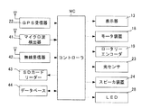
次に、図7のブロック図に基づいてレーダー探知装置10の制御部21の電気的な構成を説明する。尚、本発明とは直接関係のない構成については省略するが、レーダー探知装置として例えば従来と同様の構成を採ることがよい。
制御手段としてのコントローラMCには上記の表示器13、モータ装置18、ロータリーエンコーダ19、GPS受信機22、光センサ23、スピーカ装置24、LED28に加え、マイクロ波検出器41、無線受信器42、SDカードリーダー43、データベース44等がそれぞれ接続されている。
コントローラMCは周知のCPUやROM及びRAM等のメモリ、タイマ等から構成されている。コントローラMC内のROM内には地図データを呼び出し、得られた目標物データや速度測定装置(移動式レーダー等(以下、単に「レーダー」と称する)の検出データ等と関連付けてディスプレイ部14に表示させる地図表示プログラム、GPS受信器22によって受信されたGPS情報を処理するGPS情報処理プログラム、マイクロ波検出器41によって受信されたマイクロ波を判定するマイクロ波判定プログラム、無線受信器42よって受信された無線波を判定する無線波判定プログラム、車両診断用コネクタから出力される各種車両情報を任意に取得し、それら情報に基づいて燃料流量、各種燃費等の計算を実行する車両情報処理プログラム、ユーザーの操作によって所定のレイアウトや待ち受け用画像を表示画面14に表示させるレイアウト・待ち受け画面表示プログラム、OS(OperationSystem)等の各種プログラムが記憶されている。RAM内にはGPS受信機22で検出された位置情報や車両診断用コネクタのKラインあるいはCAN経由で取得した各種車両情報や計算された計算値等が記憶される。
Next, the electrical configuration of the
In addition to the
The controller MC includes a known CPU, a memory such as a ROM and a RAM, a timer, and the like. The map data is called into the ROM in the controller MC and displayed on the
現在位置取得手段、速度取得手段、現在時刻取得手段としてのGPS受信機22はコントローラMCの指示に基づいて現在時間における自車の位置を検出する。検出される位置情報は自車の速度、緯度、経度、高度及び時間である。マイクロ波検出器41は受信したマイクロ波から所定のマイクロ波を検出する。無線受信器42は受信した無線波から所定の無線波を検出する。SDカードリーダー43は挿入されるスロット29に挿入されるmicroSDカードのデータを読み取り、あるいはmicroSDカードのデータを更新する。データベース44はコントローラMC内、あるいはコントローラMCに外付けした不揮発性メモリ(例えばEEPROM)である。本実施の形態ではデータベース44内には主要な道路、主要な施設(例えばサービスエリア、パーキングエリア、ハイウェイオアシス、道の駅、駐車場等)、主要交通システム(例えばNシステム、ループコイル、Hシステム、LHシステム、レーダー式オービス等)の目標物の位置データ及び地図データ(模式図及び写真データ)が音声データと対応付けて記憶されている。
The
また、電気的構成において、コントローラMCは次のような制御を実行する。
コントローラMCはGPS受信器22及び(又は)光センサ23によって検出された値に基づいて表示器13を倒伏した第1の位置又は起立した第2の位置とするためにモータ装置18を駆動させる。コントローラMCはGPS受信器22又は光センサ23によって検出された値によって表示器13が現在第1の位置にある場合にそれが妥当ではないと判断した場合には第2の位置方向に移動するようにモータ装置18を駆動させる。一方、現在第1の位置にあるのが妥当と判断した場合にはモータ装置18を駆動させない。同様に表示器13が現在第2の位置にある場合にそれが妥当ではないと判断した場合には第1の位置方向に移動するようにモータ装置18を駆動させる。一方、現在第2の位置にあるのが妥当と判断した場合にはモータ装置18を駆動させない。コントローラMCはモータ装置18を駆動させた場合にロータリーエンコーダ19によって回動時の位相を取得しその値に基づいて第1の位置と第2の位置においてモータ装置18の駆動を停止させる。
Further, in the electrical configuration, the controller MC executes the following control.
Based on the values detected by the
また、コントローラMCは表示画面14に表示器13が倒伏した第1の位置にある際には倒伏モードとして例えば図4に示すような正しく読める状態の文字を裏向きに鏡像反転させ、かつ表示内容の上方側が回動基部側になるようにした表示内容で表示させる。表示画面14のレイアウトや画面に表示される情報はデータベース44内からユーザーが任意に選択してリモコンを使用して設定することが可能である。図4では間接視のレイアウトの一例として速度をデジタル式に表示する速度数字51が中央に大きく表示され、数字の斜め上にGPS警報、レーダー波警報、無線警報の対応するアイコン52が表示される。アイコン52はGPS警報、レーダー波警報、無線警報等の報知対象を検出した際に一定の時間表示画面14に表示させる。速度数字51の下方には速度のアナログ表示となる速度メーター53が表示される。
一方、表示器13が起立した第2の位置にある際には表示画面14を起立モードとして図3に示すような正しい向きで表示をさせる。このとき倒伏モードとは異なり起立した際に下側となる表示内容の下方側が回動基部側となるように表示させる。図3では直接視のレイアウトの一例として速度をアナログ式に表示する速度メーター55と速度をデジタル式に表示する速度数字56が重なるように表示され、その側方にエコメータ57と時計58が配置されている。また、それらメイン表示の下方にはGPS警報、レーダー波警報、無線警報等の報知対象を検出した際の表示としてHシステムを意味するアイコン59と、現在位置における制限速度その報知対象までの距離(ここでは50Km/H)を意味するアイコン60と、報知対象の表示(ここでは「Hシステム」)と、その報知対象までの距離と方向を示す表示61と、デジタル式の時間表示62が配置されている。アイコン52とアイコン59は同じ意味の情報であるが間接視となる図4の方を大きく表示している。本実施の形態1ではコントローラMCはロータリーエンコーダ19の数値に基づいて表示器13が第1の位置にあるのか第2の位置にあるのかを判断する。また、2種類の表示画面14の切り替えタイミングもロータリーエンコーダ19の第1の位置又は第2の位置に対応する数値に基づいて行っている。
Further, when the
On the other hand, when the
また、コントローラMCは車両診断用コネクタから取得した車両情報に基づいて車両が停車中であると判断すると、第1の位置にある表示画面14に例えば図8に示すような鏡像反転していない正しい向きでの表示をさせる。但し、この際の表示する向きとしては図3とは異なり表示内容の上方側が回動基部側となるように表示させる。つまり、図9に示すような倒伏状態にある表示画面14をフロントウィンドウFW側の外側から見た際に読みやすいように図3とは上下逆向きに表示させる。ここでの表示は第三者への警告となる標語や装飾用アニメーションや会社の宣伝広告のような運転に関する情報ではない停車中の車両内をのぞき込む第三者へのメッセージ情報である。本実施の形態1ではコントローラMCはこのようなメッセージ情報を表示画面14上でスクロール表示させる。例えば「車上狙いは犯罪です」「警報器を設置しています。車両に触らないでください」という文字表示を繰り返しスクロールさせながら表示させ一種の待ち受け画面として表示画面14を使用する。このような標語の種類やレイアウトに関する待ち受け画面用データはデータベース44内からユーザーが任意に選択してリモコンを使用して設定することが可能である。また、会社名はユーザーがリモコンを使用して、例えば「株式会社○○をよろしく」のような標語の文字情報の「○○」の部分を打ち込むようにすることでユーザーが作成した標語としてmicroSDカード内に保存させ、リモコンによって任意に呼び出して拡大・装飾等を施して文字表示として表示画面14上に表示させるようにする。
尚、図3、図4及び図8の図示では作図の都合上背景を白で表現しているが、実際の表示画面14では背景は表示内容が見やすいように黒(つまり文字等に対して相対的に暗い背景)で表示される。
Further, when the controller MC determines that the vehicle is stopped based on the vehicle information acquired from the vehicle diagnostic connector, the mirror image is not reversed as shown in FIG. 8 on the
3, 4, and 8, the background is expressed in white for convenience of drawing, but in the
また、コントローラMCは所定のタイミング(例えば1秒間隔)でGPS警報機能を実行する。コントローラMCはデータベース44に記憶された目標物の緯度及び経度データとGPS受信器22によって検出した現在位置の緯度及び経度データから両者の距離を求め、求めた距離が所定の接近距離(例えば1km以内)になった場合に、表示画面14にその旨を表示させると同時にスピーカ装置24から、例えば「1km先、高速道サービスエリアです」のようなその旨を示す接近警告の音声を出力させる。また同時にLED28にスピーカ装置24からの音声出力のタイミングに同期させて点滅による点灯警告をさせる。
また、コントローラMCはマイクロ波検出器41からのレーダーから発せられる所定の周波数帯のマイクロ波に対応する信号を検出することに基づいてレーダー波警報機能を実行する。コントローラMCはマイクロ波検出器41が所定のマイクロ波を検出したと判断するとディスプレイ部14に対してマイクロ波の種類に応じた警報画面を表示するとともに、スピーカ装置24から警報音を出力する警報機能である。例えば、レーダーの発するマイクロ波の周波数帯のマイクロ波がマイクロ波検出器41によって検出された場合に、データベース44に記憶された例えばレーダーのアイコン、模式図又は写真をディスプレイ部14に表示させるとともに、データベース44に記憶された音声データを読み出してスピーカ装置17から、例えば「50m先Hシステムです」のような音声報知をさせる。また同時にLED28にスピーカ装置24からの音声出力のタイミングに同期させて点滅による点灯警告をさせる。
コントローラMCは無線受信器15によって、緊急車両等の発する無線電波を受信した場合に、その走行等の妨げとならないよう、警報を発する無線警報機能を実行する。無線警報機能においては、取締無線、カーロケ無線、デジタル無線、特小無線、署活系無線、警察電話、警察活動無線、レッカー無線、ヘリテレ無線、消防ヘリテレ無線、消防無線、救急無線、高速道路無線、警備無線等の周波数をスキャンし、スキャンした周波数で、無線を受信した場合には、データベース44に無線種別ごとに記憶されたその周波数に対応する無線を受信した旨の例えばアイコン又は模式図を警報画面としてディスプレイ部14に表示するとともに、データベース44に無線種別ごとに記憶された音声データを読み出して、スピーカ装置24からその無線の種別を示す警報音声を出力する。たとえば、取締無線を受信した場合には、例えば「取締無線です。スピード注意」のような音声を出力させる。また同時にLED28にスピーカ装置24からの音声出力のタイミングに同期させて点滅による点灯警告をさせる。
In addition, the controller MC executes the GPS alarm function at a predetermined timing (for example, at intervals of 1 second). The controller MC obtains the distance between the latitude and longitude data of the target stored in the
Further, the controller MC executes a radar wave warning function based on detecting a signal corresponding to a microwave in a predetermined frequency band emitted from the radar from the
The controller MC executes a radio alarm function for issuing an alarm so that the
このような構成のレーダー探知装置10の動作についてコントローラMCの制御と併せて説明する。
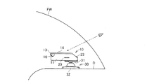
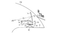
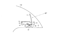
まず、図5に示すように、使用に際してユーザーはレーダー探知装置10を車両内のダッシュボードD上のフロントウィンドウFWを通して前方を目視する際の邪魔にならない位置に設置して図示しない車両診断用コネクタに接続し、メインスイッチをオン状態とする。設置にあたっては斜壁部12上に配設された光センサ23が前方、つまりフロントウィンドウFWに対峙するように本体ケース11を配置する。そして、前もって使用するユーザー(運転者)が表示画面14を直接視するための好適な位置と表示画面14がフロントウィンドウFWに反射した虚像を目視するための好適な位置となるようにユーザに対する本体ケース11の向きやダッシュボードDに対する角度等を本体ケース11をスタンド30に対して適宜動かして決めておく。
ユーザーが車両を走行可能(例えばエンジン車であればエンジンオン状態)な状態あるいはアクセサリー電源(ACC)をオン状態とすると車両診断用コネクタを介してレーダー探知装置10に自動的に電源が投入される。レーダー探知装置10の表示器13は初期状態では格納状態である図1の第1の位置(倒伏状態)にある。以下、電源投入後のコントローラMCの処理について図10のフローチャートに基づいて説明し、同時にレーダー探知装置10の動作を説明する。尚、以下のような処理は頻繁に行うと表示器13の起立と倒伏が短いタイミングで何度も行われ煩わしく感じられる可能性があるため、明るさが大きく変化する可能性のある時間帯や天候の変化を考慮した長いインターバルの分単位あるいは時間単位で実行することがよい。例えば以下は10分毎に実行される。
まず、ステップS1においてコントローラMCはGPS受信器22によって受信された位置情報と時間情報に基づいて現在が夜なのか昼間なのかを判断する。そして、ステップS1で夜であると判断した場合には、ステップS2でコントローラMCは表示器13が現在第1の位置かどうかを判断する。これは上記のロータリーエンコーダ19の検出値に基づいて判断される。ステップS2で第1の位置であると判断すると、ステップS3でコントローラMCは表示画面14に通常の読める態様の表示内容を鏡像反転させた裏向きの態様で、かつ表示内容全体の上方側が表示画面14の基部側(つまり直接視した場合の下方側)となるように表示画面14に表示させるように制御して処理は一旦終了する。このような場合では図5及び図6のように表示画面14はフロントウィンドウFWによって反射させられ、その虚像があたかもフロントウィンドウFWの外側の中空に浮かぶように表示されてユーザーに目視されることとなる。この虚像の状態での文字情報は人が通常読める(認識できる)正しい向きであり、また、表示される像の上側がユーザーの視野上方側でこれも人が通常認識できる正しい上下方向となる。この際、夜間であるため周囲は暗くなっており、夜間において直接視ではまぶしく感じることの多い表示画面14がまぶしすぎることなく、フロントウィンドウFWで反射されて光量が減衰されることでユーザーはちょうどよい光量で表示画面14を見ることができる。
一方、ステップS2で表示器13が第1の位置にはない(つまり第2の位置にある)と判断すると、ステップS4で表示器13を第1の位置に移動させるためにモータ装置18を駆動させて表示器13が第1の位置に移動させる。そして、コントローラMCはステップS3の処理を実行させる。
The operation of the
First, as shown in FIG. 5, in use, the user installs the
When the user can drive the vehicle (for example, if the engine is an engine, the engine is turned on) or the accessory power supply (ACC) is turned on, the
First, in step S1, the controller MC determines whether the current time is night or daytime based on the position information and time information received by the
On the other hand, if it is determined in step S2 that the
これに対して、コントローラMCはステップS1で夜ではないと判断した場合には、昼間であるとしてここで初めてステップS5において光センサ23によって明るさが所定のしきい値よりも上かどうか、つまり十分明るいかどうかを判断する。このようにまずGPS受信器22での判断を先に実行させその後に光センサ23での判断を行うようにしているのは、光センサ23だけの判断では例えば夜間に使用される車のヘッドライトの光等で光センサ23がしきい値よりも高い値を算出してしまうことがあるため、そのような場合の誤作動を防止するためである。ステップS5で明るさが所定のしきい値より上であると判断した場合には、ステップS6で上記と同様にコントローラMCは表示器13が現在第1の位置かどうかを判断する。この場合第2の位置に表示器13があることがよいため、第1の位置であると判断すると、コントローラMCはステップS7でモータ装置18を駆動させて表示画面14を第2の位置(起立状態)に移動させ、ステップS8で表示内容を裏向きに反転していない正しい画像として、かつ表示内容全体の下方側が表示画面14の基部側となるように(つまり上記と同様通常人が通常認識できる正しい上下方向)表示画面14に表示させるように制御して処理は一旦終了する。このような場合では図3のように本体ケース11の手前側(つまり、ユーザの近くで)においてユーザーは直接表示画面14を目視できることとなる。このとき十分光のある昼間であるため、ユーザーは瞳孔が開くため直接視で表示画面14を見てもまぶしく感じることはなく、ユーザーはちょうどよい光量で見ることができる。
一方、ステップS6で第1の位置ではないと判断すると、表示器13はすでに第2の位置(起立状態)にあると判断して処理はステップS8に移行してコントローラMCはステップS8の処理を実行させる。
On the other hand, if the controller MC determines that it is not night in step S1, whether or not the brightness is higher than a predetermined threshold value by the
On the other hand, if it is determined in step S6 that the position is not the first position, it is determined that the
これに対して、ステップS5で明るさが所定のしきい値より下であると判断した場合には、周囲が明るくないということで夜ではないものの光量の少ない雨天、曇天、夕方等であると判断する。そして、コントローラMCはステップS9で上記と同様にコントローラMCは表示器13が現在第1の位置かどうかを判断する。この場合第1の位置に表示器13があることがよいため、第1の位置であると判断すると、ステップS10でコントローラMCは表示画面14に通常の読める態様の表示内容を鏡像反転させた裏向きの態様で、かつ表示内容全体の上方側が表示画面14の基部側(つまり直接視した場合の下方側)となるように表示画面14に表示させるように制御して処理は一旦終了する。一方、ステップS9で第1の位置ではないと判断すると表示器13は第2の位置(起立状態)にあると判断してコントローラMCはステップS11でモータ装置18を駆動させて表示画面14を第1の位置(起立状態)に移動させ、次いでコントローラMCはステップS10の処理を実行させ処理は一旦終了する。
On the other hand, when it is determined in step S5 that the brightness is lower than the predetermined threshold, it is not rainy because the surroundings are not bright, but it is rainy, cloudy, evening or the like with little light. to decide. In step S9, the controller MC determines whether the
このような構成においては、車両走行中にレーダー探知装置10がGPS警報、レーダー波警報、無線警報等の報知対象を検出した際には第1の位置(倒伏状態)であっても第2の位置(起立状態)であっても表示画面14にそれぞれの位置で例えば図3や図4のように表示され、ユーザーは表示内容を間接的あるいは直接的に適切な目視環境で目視することができる。同時にスピーカ装置24から音声が音声孔25を通じて報知され、LED28が点滅することでマーク入りパネル27の絵柄27aが点滅しながら光ってユーザーに注意喚起がされる。
そして、車両が停止した際にコントローラMCは車両診断用コネクタから車両のエンジン停止情報を検出すると、レーダー探知装置10の表示器13が第1の位置(倒伏状態)にある場合にはその位置で、第2の位置(起立状態)にある場合には第1の位置(倒伏状態)に移動するようにモータ装置18を駆動させ、ユーザーへの運転情報を報知するための制御を終了させる。
また、コントローラMCは車両のエンジン停止を検出すると所定時間後に表示画面14上に図3の向きとは上下逆向きにした表示内容が鏡像反転していない正しい画像、例えば図9のような一種の待ち受け画像として表示させる。
In such a configuration, when the
When the controller MC detects the vehicle engine stop information from the vehicle diagnosis connector when the vehicle is stopped, if the
Further, when the controller MC detects that the engine of the vehicle is stopped, a correct image in which the display content reversed in the upside down direction with respect to the direction of FIG. Display as a standby image.
ユーザーは図示しないリモコンを操作して赤外線受光部26から設定条件を任意に変更できる。例えば、表示画面14のレイアウトや画面に表示される種々の情報の種類を入れ替え変更したり(図3や図4以外のレイアウトや図3や図4で表示されている運転に関する情報を表示させたり)、表示画面14の明るさを変更したり、スピーカ装置24からの音声出力を停止させたり、表示器13を常に第1の位置(倒伏状態)のみで使用するようにしたり、逆に常に第2の位置(起立状態)のみで使用するようにする。あるいは表示画面14の表示機能をまったく使用しない(つまり表示器13を第1の位置に保持させる)でスピーカ装置24からの音声出力又は(及び)マーク入りパネル27の絵柄27aの点灯だけで情報報知をさせるように使用する。
また、ユーザーはリモコンを操作して待ち受け画像を表示させるかどうかの設定が可能である。また、表示させる場合においては表示されるタイミングや待ち受け画像の種類、スクロールさせるかどうかの表示方法等の設定条件を任意に変更することができる。
The user can arbitrarily change the setting conditions from the infrared
In addition, the user can set whether to display a standby image by operating the remote controller. In the case of display, setting conditions such as the display timing, the type of standby image, and the display method for whether to scroll can be arbitrarily changed.
上記のように構成することにより本実施の形態1のレーダー探知装置10では次のような効果が奏される。
(1)表示画面14を目視する条件として直接視と間接視が明るさによって自動的に変更が行われることから夜間や暗い日中等の条件でも明るい昼間の条件でもユーザーにとってより見やすい適切な環境下での情報入手が可能となっている。
(2)直接視と間接視で同じ表示器13の表示画面14を使用しているため、レーダー探知装置10はコンパクト化、軽量化され、狭い車両内でユーザーが本機を設置する際において取り扱いやすく設置場所の裕度も増すため有利である。
(3)間接視においては表示画面14の虚像は直接視する場合よりも遠い位置に表示され、かつ明るさも相対的に減衰する。更に、フロントウィンドウFWの厚みによって虚像が二重写しになる可能性もある。しかし、間接視における表示画面14の表示内容は直接視におけるそれとは異なる表示態様で、かつより単純で大きな図柄とすることで見やすいものとしている。
(4)表示器13は車両の停止の際には倒伏した第1の位置に配置されているため、ユーザの車両への乗り降りや車内の掃除等の作業において起立した表示器13が邪魔となりにくい。
(5)直接視でも間接視でも表示画面14からGPS警報、レーダー波警報、無線警報の報知がされることとなるため、ユーザーにとってレーダー探知装置10の基本的機能は維持される。特に間接視ではユーザは何の報知か分かりにくいため間接視となる方を大きく表示することで見やすさを向上させている。
(6)ユーザーの操作で例えばスピーカ装置24からの音声出力を停止させたり、逆に表示画面14の表示機能を使用せずに音声出力又は(及び)マーク入りパネル27の絵柄27aの点灯だけでも情報報知を受けることができるため、ユーザーにとって様々なモードでの情報取得が可能となっている。
(7)GPS受信器22や光センサ23はデータを取得しやすい側に配置されるようになっているため、より正確な情報をユーザーに取得させることが可能となっている。
(8)車両が停止して駐車状態にあっては第1の位置(倒伏状態)にある表示器13の表示画面14上に待ち受け画像を表示させるようにしたため、ユーザーの所望で駐車中に第三者に様々なメッセージを発信することが可能となる。
(9)表示器13はLCDモジュールの基板のみから構成され、余分なフレームを外周にまとっていないため軽量化できてモータ装置18の駆動時の負荷が少なくなる。そして、両耳状支持部16を介して支持されると同時にフレキコード15によっても支えられることから、軽量化しても車両の振動で表示画面14が大きく揺れることがなくユーザーにとって見やすい画面となっている。
(10)表示画面14としてLCDのようなバックライト光によって光を発するドットマトリクスディスプレイを使用しているため、間接視では例えばヘッドライトが必要となるような周囲が暗くなる状況、例えば夜間等に限定すればよいためそれほど大きな輝度が必要ではなく、一方で例えば昼間など周囲が明るい状況ではユーザーに表示画面14を直接的に目視させることができる。そして、安価な汎用液晶等のドットマトリクスディスプレイを使用することができ低コスト化に寄与する。また、直接見ても高解像度できれいな表示を保つことができる。
With the configuration described above, the
(1) Direct viewing and indirect viewing are automatically changed depending on the brightness as a condition for viewing the
(2) Since the
(3) In indirect viewing, the virtual image on the
(4) Since the
(5) Since the GPS alarm, the radar wave alarm, and the radio alarm are notified from the
(6) For example, the sound output from the
(7) Since the
(8) Since the standby image is displayed on the
(9) The
(10) Since a dot matrix display that emits light by backlight light such as an LCD is used as the
(実施の形態2)
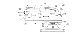
実施の形態2は実施の形態1に反射体としての反射プレート71を配設したものである。実施の形態2の図示において実施の形態1と同じ構成については同じ符号を付すことで詳しい説明は省略する。図11〜図13に示すように、実施の形態2のレーダー探知装置70の本体ケース11の天板11b側には反射プレート71が配設されている。反射プレート71はポリカーボネート製の透明な一体成形部材である。反射プレート71は内側面が上下方向及び左右方向において凹状にわずかに湾曲して形成された直方体形状の外形の本体72と本体72基部に形成された左右一対の脚部73から構成されている。反射プレート71の端面全周にかけて曇りガラス状の粗面処理がされている(但し、後述するように一部のみは透明のままに構成されている)。本体72は左右幅方向において表示器13よりも幅広に構成され、上下長さ方向は同じ長さに構成されている(全体の大きさとして表示器13よりも大きく構成されている)。反射プレート71の外側面には反射防止コートが施されている。
図14に示すように、両脚部73の内側にはそれぞれ円板74が形成されている。円板74の中央には回動軸75が突出形成され、円板74の外周には4つの係合突部76a〜76dが形成されている。図15に示すように、反射プレート71は脚部73の回動軸75を本体ケース11の両側壁11dの後部寄り位置(斜壁部11aに隣接した位置)に形成された軸孔77に対して軸支させることで本体ケース11に対して揺動可能とされる。反射プレート71は両脚部73を外方に撓ませて軸孔77から回動軸75を外すことで取り外し可能である。
(Embodiment 2)
In the second embodiment, a
As shown in FIG. 14,
本体ケース11の軸孔77に隣接した位置には断面円形の突起78が形成されている。図14及び図15に示すように、反射プレート71が本体ケース11に装着された状態で突起78は係合突部76a〜76dと干渉可能な位置に配置されている。そのため反射プレート71は所定以上のトルクを付与しないと突起78に係合突部76a〜76dが干渉し反射プレート71を回動させることができない。一方、所定以上のトルクを付与すれば円板74や突起78が撓んで係合突部76a〜76dが突起78を乗り越えていくため反射プレート71を回動させることができる。本実施の形態2では図14(a)の反射プレート71が起立した位置では突起78が係合突部76aと係合突部76bの間に嵌まり込んでいずれの方向にも回動しにくくなって反射プレート71は保持される。一方、図14(b)の反射プレート71が倒伏した位置では突起78が係合突部76cと係合突部76dの間に嵌まり込んで同様に反射プレート71は保持される。本実施の形態2では隣接する各係合突部76a〜76d間の3カ所の位置で突起78が嵌まり込んで反射プレート71の姿勢を保持することが可能となっている。
図12及び図13に示すように、反射プレート71が起立保持された状態では表示器13が第1の位置(倒伏した位置)と第2の位置(起立した位置)に往復移動する際の軌道内にはないため、反射プレート71が表示器13の移動の邪魔になることはない。表示器13が第1の位置(倒伏した位置)にある場合には図11のように上方から表示器13上に重ねて表示器13を保護したり表示画面14での表示をしない場合のカバーとすることができる。
図11〜図13に示すように、本体ケース11の後方の斜壁部11aにはLED80が配設されている。LED80は反射プレート71に隣接した位置に配置され、反射プレート71が起立した状態で照射方向が反射プレート71の端面に面して内部方向を指向するように配置されている。LED80と対峙した端面部分のみは粗面処理されずに透明な状態とされており光が進入しやすくなっている。
A
As shown in FIGS. 12 and 13, when the
As shown in FIGS. 11 to 13, the
図17は実施の形態2におけるレーダー探知装置70の制御部21の電気的な構成を説明するブロック図である。コントローラMCには上記実施の形態1の電気的構成に加えてLED80が接続されている。コントローラMCはイベントが発生するとそのイベントに応じてLED80を点灯させ所定の点滅表示をさせてユーザーの注意を喚起する。イベントとしては、本実施の形態2では車両走行中にレーダー探知装置70がGPS警報、レーダー波警報、無線警報等の報知対象を検出した場合(つまり、同時に表示画面14にはその旨が表示される)と、0分ちょうどの各時刻を取得した場合、ユーザーのリモコン入力によるユーザーの誕生日(誕生日当日の最初のレーダー探知装置70の起動時に実行させる)が用意されている。ユーザーは図示しないリモコンを操作して赤外線受光部26からLED80の発光について発光させるかどうかや発光させる場合にどのようなイベントで発光させるか等の設定条件を任意に変更できる。
FIG. 17 is a block diagram illustrating an electrical configuration of the
このような構成のレーダー探知装置70の動作について説明する。
使用に際してユーザーは実施の形態1と同様の操作でレーダー探知装置70を車両内のダッシュボードD上に設置する。そして、当初図11の反射プレート71を保護カバーとして第1の位置にある表示器13に重ねた位置から手動にて操作して図12の起立させた状態とする。以後の使用方法は実施の形態1のレーダー探知装置10と同様である。
このような構成とすることで、実施の形態2のレーダー探知装置70も実施の形態1のレーダー探知装置10と同様にユーザーは表示画面14に表示された表示内容を間接的あるいは直接的に適切な目視環境で目視することができる。実施の形態2では間接視においては図16に示すように表示画面14は反射プレート71の内側面によって反射させられ、その虚像があたかもフロントウィンドウFWの外側の中空に浮かぶように表示されてユーザーに目視されることとなる。また、実施の形態2でも実施の形態1と同様にスピーカ装置24から音声が音声孔25を通じて報知され、LED28が点滅することでマーク入りパネル27の絵柄27aが点滅しながら光ってユーザーに注意喚起がされる。
また、イベント発生時においてはLED80が点滅しながら発光して反射プレート71を照射する。
車両が停止した場合には上記実施の形態1と同様に表示器13は第1の位置(倒伏状態)に位置することとなる。反射プレート71は車両が停止しても起立状態であるため、ユーザーは所望によって手動で反射プレート71を本体ケース11に対して倒伏方向に回動させて図11の状態とする。
The operation of the
In use, the user installs the
By adopting such a configuration, similarly to the
Further, when an event occurs, the
When the vehicle stops, the
上記のように構成することにより本実施の形態2のレーダー探知装置70では上記実施の形態1の効果に加えて次のような効果が奏される。
(1)間接視においてはフロントウィンドウFWとは別に反射プレート71を設けているため、より近い位置でのユーザーの間接視が可能となるため、表示画面14をそれほど明るい仕様にしなくともよくなる。
(2)反射プレート71には反射防止コートを施しているため、画像が二重になりにくく鮮明な虚像を得ることができる。
(3)反射プレート71は格納時において表示器13に重ねて配置するようになっており、ユーザーが表示画面14を見ないという設定にしている場合に保護カバーとして役立つ。
(4)反射プレート71は適宜取り外すことができ、取り外しても車両情報の報知はされるためユーザの方針に合わせた使用が可能である。
(5)反射プレート71によって間接視ができるためレーダー探知装置70を必ずしもフロントウィンドウFWの前に配置しなくともよく、ユーザーにおいて配置位置の裕度が向上する。
(6)反射プレート71は反射面が凹面状に形成されているため映される表示内容が拡大されることとなり、ユーザーは見やすくなる。
(7)上記レーダー探知装置10では位置を変える表示器13の位置決めと反射プレート71のためにスタンド30はブラケット部31とベース32から構成するようにして、ベース32に対してブラケット部31を十分な可動範囲で自在な位置に変位できるようにした。そのため、表示器13と反射プレート71は回動できずに2つの定位置間を移動するだけであるが、表示器13も反射プレート71も十分ユーザーにとって見やすい位置に配置することができる。
(8)イベント発生時においてはLED80が点滅しながら発光して反射プレート71を照射する。ため反射プレート71の端部はその光を乱反射させて反射プレート71を包囲するようなイルミネーション効果を奏することとなり、ユーザーの遊び心を喚起することとなる。
By configuring as described above, the
(1) In the indirect viewing, since the
(2) Since the
(3) The
(4) The
(5) Since indirect viewing is possible with the
(6) Since the reflection surface of the
(7) In the
(8) When an event occurs, the
本発明を、以下のような態様で具体化して実施してもよい。
・上記実施の形態1では車両がエンジンを停止させて駐車させている状態でフロントウィンドウFWの外から第三者がダッシュボードDの上に設置されたレーダー探知装置10の倒伏した表示画面14をボンネット側から目視させるような構成であった。これを例えば、実施の形態2においては図18に示すように起立させた反射プレート71に反射する虚像を目視させるようにしてもよい。この場合には反射プレート71の運転者(ユーザー)側の裏面となる側から第三者は目視するわけであるから、表示画面14に表示される上記実施の形態1と同様に鏡像反転していない正しい向きで、図8と同様に倒伏状態にある表示画面14をフロントウィンドウFW側の外側から見た際に読みやすいように図3とは上下逆向きに表示させる。もちろん、実施の形態2でも反射プレート71を取り外して実施の形態1のような直接第三者に表示画面14を目視させるような構成を採択することも可能である。ユーザーがどちらかのパターンでの表示を選択するようにしてもよい。
・上記実施の形態2では拡大レンズ効果のある反射面が凹面に構成された反射プレート71を用意するようにしたが、反射プレート71は取り外し可能であるため、反射面が平面に構成された反射プレートを付け替え用に用意してデフォルトで用意された反射プレート71と交換可能にしてもよい。このように構成すれば、ユーザーは自身の好みやいずれか見やすい方のプレートを選択することができる。
・上記各実施の形態では図示しないリモコンを使用してユーザーは各種入力や設定モードの変更操作を行うようにしていたが、タッチパネル方式にしたり、別途でスイッチを本体ケース11等に設けるようにしてもよい。
・表示器13の回動位置の検出は上記各実施の形態ではロータリーエンコーダ19を使用したが他の検出手段、例えばリミットスイッチや近接スイッチ等を使用してもよい。
・上記各実施の形態では表示器13を回動させるモータ装置18としてはブラシレスDCモータを使用したが他の種類のモータ、例えばサーボモータ、リニアモータ等を使用してもよい。
・上記各実施の形態では表示器13の倒伏と起立はモータ装置18を制御して自動的に行うようにしていたが、モータ装置18のような駆動手段を使用せずユーザーが手動で操作することで行ってもよい。例えば、デフォルト状態で表示器13を倒伏させていて、光センサ23のような明るさを検出できる手段によって検出した結果、起立させた方が(つまり表示画面14を直接目視させた方が)よいと判断できる明るさが続いているとコントローラMCが判断した場合にユーザーにその旨を報知し、ユーザーの操作によって(操作手段としては手動あるいは例えばリモコンや入力スイッチでもよい)倒伏状態から起立状態をするような場合(あるいはその逆)である。モータのような駆動手段によらずにユーザーが手動で表示器13の倒伏と起立を行ってもよい。また、報知は表示画面に切り換えた方が見やすい旨の文字表示の視覚による報知やスピーカ装置からの音声やチャイム等の注意喚起音による聴覚による報知やそれらの両方を含んでもよい。また、明るさを検出できる手段がなくともユーザーの主観でこのようにユーザーの操作によって倒伏状態と起立状態を切り換えるようにしてもよい。このような場合でも表示器13の回動位置の検出は上記のようなロータリーエンコーダ19や他の検出手段を使用できる。
The present invention may be embodied in the following aspects.
In the first embodiment, the
In the second embodiment, the
In each of the above embodiments, the user performs various inputs and setting mode changing operations using a remote controller (not shown). However, a touch panel method or a separate switch is provided on the
In the above embodiments, the
In each of the above embodiments, a brushless DC motor is used as the
In each of the above-described embodiments, the
・上記各実施の形態では表示器13の倒伏と起立はGPS受信器22と光センサ23の両方を使用したが、いずれか一方だけでもよい。
・表示画面14となる液晶ディスプレイのバックライトの光量を表示器13を倒伏させた間接視の状態と起立させた直接視の状態で変えるようにしてもよい。例えば、間接視では直接視に対して相対的に暗くなるため、よりバックライトの光量を直接視の場合よりも明るくするようにコントローラMCが制御してもよい。逆に直接視の場合を間接視に対して相対的に暗くするように制御してもよい。
・上記各実施の形態では電子機器として車両内のダッシュボードDの上にレーダー探知装置10を設置する一例を挙げたが、車両内に配置することもダッシュボードD上に設置することも一例であり車載用の電子機器以外として使用するようにしてもよい。従って、車のフロントウィンドウFW以外に反射させるようにしてもよい。また車両内であっても他の位置、例えば、図5に示すAピラーPにレーダー探知装置10を配置するようにしてもよい。
・表示画面14となるデバイスとして液晶ディスプレイ以外の他の発光デバイス、例えば有機エレクトロルミネッセンス(OEL)やLEDを使用してもよい。
・反射プレート71の材質は透明であればよく、上記以外に例えばアクリル、ポリエステル等の透明プラスチックを使用することができる。
本発明はその趣旨を逸脱しない範囲において変更した態様で実施することは自由である。
In each of the above-described embodiments, both the
-You may make it change the light quantity of the backlight of the liquid crystal display used as the
In each of the above-described embodiments, an example in which the
-As a device used as the
The material of the
The present invention can be freely implemented in a modified form without departing from the spirit of the present invention.
10…電子情報システムとしてのレーダー探知装置、14…表示画面、71…反射体としての反射プレート、FW…反射体としてのフロントウィンドウ。
DESCRIPTION OF
Claims (26)
Priority Applications (1)
| Application Number | Priority Date | Filing Date | Title |
|---|---|---|---|
| JP2015244778A JP2017109577A (en) | 2015-12-16 | 2015-12-16 | Information display system |
Applications Claiming Priority (1)
| Application Number | Priority Date | Filing Date | Title |
|---|---|---|---|
| JP2015244778A JP2017109577A (en) | 2015-12-16 | 2015-12-16 | Information display system |
Related Child Applications (1)
| Application Number | Title | Priority Date | Filing Date |
|---|---|---|---|
| JP2020212123A Division JP7213561B2 (en) | 2020-12-22 | 2020-12-22 | Information display system |
Publications (1)
| Publication Number | Publication Date |
|---|---|
| JP2017109577A true JP2017109577A (en) | 2017-06-22 |
Family
ID=59079980
Family Applications (1)
| Application Number | Title | Priority Date | Filing Date |
|---|---|---|---|
| JP2015244778A Pending JP2017109577A (en) | 2015-12-16 | 2015-12-16 | Information display system |
Country Status (1)
| Country | Link |
|---|---|
| JP (1) | JP2017109577A (en) |
Cited By (9)
| Publication number | Priority date | Publication date | Assignee | Title |
|---|---|---|---|---|
| JP2018081220A (en) * | 2016-11-17 | 2018-05-24 | 株式会社Nttドコモ | Display system and program |
| JP2019045843A (en) * | 2017-09-01 | 2019-03-22 | 和全豐光電股▲ふん▼有限公司 | Optical projection system |
| CN110091806A (en) * | 2018-01-30 | 2019-08-06 | 丰田自动车株式会社 | Display apparatus |
| JP2021025883A (en) * | 2019-08-06 | 2021-02-22 | セルスター工業株式会社 | Notification device |
| CN113272170A (en) * | 2019-02-06 | 2021-08-17 | 宝马股份公司 | Vehicle with adjustable screen |
| KR20220054138A (en) * | 2020-10-23 | 2022-05-02 | 주식회사 디티앤바이오 | External cluster for supporting operation status and media functions by interlocking with vehicle using CAN communication |
| JP2022155434A (en) * | 2021-03-30 | 2022-10-13 | 株式会社ユピテル | System and program |
| WO2024048867A1 (en) * | 2022-09-02 | 2024-03-07 | 엘지전자 주식회사 | Display device for vehicle |
| WO2025162538A1 (en) * | 2024-01-30 | 2025-08-07 | Bayerische Motoren Werke Aktiengesellschaft | Arrangement and method for displaying contents in a motor vehicle |
Citations (14)
| Publication number | Priority date | Publication date | Assignee | Title |
|---|---|---|---|---|
| JPS63202529U (en) * | 1987-06-22 | 1988-12-27 | ||
| JPH02241843A (en) * | 1989-03-15 | 1990-09-26 | Nissan Motor Co Ltd | Display device for vehicle |
| JPH08160882A (en) * | 1994-11-30 | 1996-06-21 | Nippon Seiki Co Ltd | Display device |
| JPH0933856A (en) * | 1995-07-24 | 1997-02-07 | Denso Corp | Display device |
| JPH09230282A (en) * | 1996-02-21 | 1997-09-05 | Asahi Glass Co Ltd | Display device |
| US5963280A (en) * | 1995-12-05 | 1999-10-05 | Matsushita Electric Industrial Co., Ltd. | Backlighting device and color display device |
| JP2001166702A (en) * | 1999-12-06 | 2001-06-22 | Nissan Motor Co Ltd | Vehicle display system |
| JP2005028982A (en) * | 2003-07-11 | 2005-02-03 | Alpine Electronics Inc | In-vehicle display device |
| JP2005335555A (en) * | 2004-05-27 | 2005-12-08 | Nissan Motor Co Ltd | Vehicle information presentation apparatus and vehicle information presentation method |
| JP2006195007A (en) * | 2005-01-11 | 2006-07-27 | Fujitsu Ten Ltd | Display device |
| JP3134641U (en) * | 2007-05-14 | 2007-08-23 | 永發 林 | Electronic compass |
| JP2013040846A (en) * | 2011-08-15 | 2013-02-28 | Zenrin Datacom Co Ltd | Navigation device and navigation method |
| US20140333647A1 (en) * | 2013-05-13 | 2014-11-13 | Samsung Display Co., Ltd. | Head-up display system, and method and apparatus for controlling the same |
| JP2015024813A (en) * | 2013-07-25 | 2015-02-05 | ビステオン グローバル テクノロジーズ インコーポレイテッド | Articulating instrument cluster |
-
2015
- 2015-12-16 JP JP2015244778A patent/JP2017109577A/en active Pending
Patent Citations (14)
| Publication number | Priority date | Publication date | Assignee | Title |
|---|---|---|---|---|
| JPS63202529U (en) * | 1987-06-22 | 1988-12-27 | ||
| JPH02241843A (en) * | 1989-03-15 | 1990-09-26 | Nissan Motor Co Ltd | Display device for vehicle |
| JPH08160882A (en) * | 1994-11-30 | 1996-06-21 | Nippon Seiki Co Ltd | Display device |
| JPH0933856A (en) * | 1995-07-24 | 1997-02-07 | Denso Corp | Display device |
| US5963280A (en) * | 1995-12-05 | 1999-10-05 | Matsushita Electric Industrial Co., Ltd. | Backlighting device and color display device |
| JPH09230282A (en) * | 1996-02-21 | 1997-09-05 | Asahi Glass Co Ltd | Display device |
| JP2001166702A (en) * | 1999-12-06 | 2001-06-22 | Nissan Motor Co Ltd | Vehicle display system |
| JP2005028982A (en) * | 2003-07-11 | 2005-02-03 | Alpine Electronics Inc | In-vehicle display device |
| JP2005335555A (en) * | 2004-05-27 | 2005-12-08 | Nissan Motor Co Ltd | Vehicle information presentation apparatus and vehicle information presentation method |
| JP2006195007A (en) * | 2005-01-11 | 2006-07-27 | Fujitsu Ten Ltd | Display device |
| JP3134641U (en) * | 2007-05-14 | 2007-08-23 | 永發 林 | Electronic compass |
| JP2013040846A (en) * | 2011-08-15 | 2013-02-28 | Zenrin Datacom Co Ltd | Navigation device and navigation method |
| US20140333647A1 (en) * | 2013-05-13 | 2014-11-13 | Samsung Display Co., Ltd. | Head-up display system, and method and apparatus for controlling the same |
| JP2015024813A (en) * | 2013-07-25 | 2015-02-05 | ビステオン グローバル テクノロジーズ インコーポレイテッド | Articulating instrument cluster |
Cited By (21)
| Publication number | Priority date | Publication date | Assignee | Title |
|---|---|---|---|---|
| JP2018081220A (en) * | 2016-11-17 | 2018-05-24 | 株式会社Nttドコモ | Display system and program |
| JP2019045843A (en) * | 2017-09-01 | 2019-03-22 | 和全豐光電股▲ふん▼有限公司 | Optical projection system |
| JP7095291B2 (en) | 2018-01-30 | 2022-07-05 | トヨタ自動車株式会社 | Display device for vehicles |
| JP2019130971A (en) * | 2018-01-30 | 2019-08-08 | トヨタ自動車株式会社 | Vehicle display device |
| US11338678B2 (en) | 2018-01-30 | 2022-05-24 | Toyota Jidosha Kabushiki Kaisha | Vehicle display device |
| CN110091806A (en) * | 2018-01-30 | 2019-08-06 | 丰田自动车株式会社 | Display apparatus |
| US12011998B2 (en) | 2018-01-30 | 2024-06-18 | Toyota Jidosha Kabushiki Kaisha | Vehicle display device |
| CN110091806B (en) * | 2018-01-30 | 2022-10-28 | 丰田自动车株式会社 | Display device for vehicle |
| US11820225B2 (en) | 2018-01-30 | 2023-11-21 | Toyota Jidosha Kabushiki Kaisha | Vehicle display device |
| CN113272170A (en) * | 2019-02-06 | 2021-08-17 | 宝马股份公司 | Vehicle with adjustable screen |
| JP2022519272A (en) * | 2019-02-06 | 2022-03-22 | バイエリシエ・モトーレンウエルケ・アクチエンゲゼルシヤフト | Vehicles with adjustable displays |
| US12151556B2 (en) | 2019-02-06 | 2024-11-26 | Bayerische Motoren Werke Aktiengesellschaft | Vehicle having an adjustable display screen |
| JP7471310B2 (en) | 2019-02-06 | 2024-04-19 | バイエリシエ・モトーレンウエルケ・アクチエンゲゼルシヤフト | Vehicle with adjustable display |
| JP2021025883A (en) * | 2019-08-06 | 2021-02-22 | セルスター工業株式会社 | Notification device |
| JP7317360B2 (en) | 2019-08-06 | 2023-07-31 | セルスター工業株式会社 | Notification device |
| KR102443046B1 (en) * | 2020-10-23 | 2022-09-14 | 주식회사 디티앤바이오 | External cluster for supporting operation status and media functions by interlocking with vehicle using CAN communication |
| KR20220054138A (en) * | 2020-10-23 | 2022-05-02 | 주식회사 디티앤바이오 | External cluster for supporting operation status and media functions by interlocking with vehicle using CAN communication |
| JP2022155434A (en) * | 2021-03-30 | 2022-10-13 | 株式会社ユピテル | System and program |
| WO2024048867A1 (en) * | 2022-09-02 | 2024-03-07 | 엘지전자 주식회사 | Display device for vehicle |
| EP4545335A4 (en) * | 2022-09-02 | 2025-11-05 | Lg Electronics Inc | DISPLAY DEVICE FOR A VEHICLE |
| WO2025162538A1 (en) * | 2024-01-30 | 2025-08-07 | Bayerische Motoren Werke Aktiengesellschaft | Arrangement and method for displaying contents in a motor vehicle |
Similar Documents
| Publication | Publication Date | Title |
|---|---|---|
| JP2017109577A (en) | Information display system | |
| JP6118957B2 (en) | Vehicle system and program | |
| CN107206901A (en) | Display apparatus | |
| JP2012242586A (en) | Display device | |
| CN114994966A (en) | Display and light-blocking screens | |
| JP7829260B2 (en) | Display device and program | |
| JP7760181B2 (en) | Vehicle system and program | |
| JPH08227498A (en) | Head-up display for vehicle and navigation device using the same | |
| JP6427779B2 (en) | Vehicle system and program | |
| JP6155495B2 (en) | Vehicle system and program | |
| JP6355285B2 (en) | Vehicle system and program | |
| JP6216941B2 (en) | Electronic device and program | |
| US8379043B1 (en) | Methods and apparatus for displaying information on the inside of a windshield | |
| JP6155443B2 (en) | Vehicle system and program | |
| JP2025111684A (en) | System and program for vehicle | |
| JP6706726B2 (en) | Vehicle system and program | |
| JP7213561B2 (en) | Information display system | |
| JP2015157509A (en) | Vehicular warning device and vehicular warning unit | |
| JP2019131182A (en) | Display device and program | |
| JP6823767B2 (en) | Vehicle systems and programs | |
| JP7627970B2 (en) | Vehicle system and program | |
| JP2016084103A (en) | Display device and program | |
| JP7702755B2 (en) | Electronic devices and programs | |
| JP2018091853A (en) | Vehicle system and program | |
| JP2024055104A (en) | Head-up display device |
Legal Events
| Date | Code | Title | Description |
|---|---|---|---|
| A621 | Written request for application examination |
Free format text: JAPANESE INTERMEDIATE CODE: A621 Effective date: 20181204 |
|
| A131 | Notification of reasons for refusal |
Free format text: JAPANESE INTERMEDIATE CODE: A131 Effective date: 20190911 |
|
| A521 | Request for written amendment filed |
Free format text: JAPANESE INTERMEDIATE CODE: A523 Effective date: 20191108 |
|
| A131 | Notification of reasons for refusal |
Free format text: JAPANESE INTERMEDIATE CODE: A131 Effective date: 20200422 |
|
| A521 | Request for written amendment filed |
Free format text: JAPANESE INTERMEDIATE CODE: A523 Effective date: 20200605 |
|
| A02 | Decision of refusal |
Free format text: JAPANESE INTERMEDIATE CODE: A02 Effective date: 20200930 |