JP2017111908A - Vehicle headlamp - Google Patents
Vehicle headlamp Download PDFInfo
- Publication number
- JP2017111908A JP2017111908A JP2015244027A JP2015244027A JP2017111908A JP 2017111908 A JP2017111908 A JP 2017111908A JP 2015244027 A JP2015244027 A JP 2015244027A JP 2015244027 A JP2015244027 A JP 2015244027A JP 2017111908 A JP2017111908 A JP 2017111908A
- Authority
- JP
- Japan
- Prior art keywords
- air supply
- vehicle
- supply duct
- housing
- bonnet
- Prior art date
- Legal status (The legal status is an assumption and is not a legal conclusion. Google has not performed a legal analysis and makes no representation as to the accuracy of the status listed.)
- Pending
Links
Images


Landscapes
- Cooling, Air Intake And Gas Exhaust, And Fuel Tank Arrangements In Propulsion Units (AREA)
- Non-Portable Lighting Devices Or Systems Thereof (AREA)
Abstract
【課題】車両の外形を形成する車体パネルの一部を構成するボンネットやサイドパネル上に堆積した雪を簡単な構成で溶かして機能低下を防ぐことができる車両用前照灯を提供すること。【解決手段】ハウジング12とその前面開口部を覆うアウタレンズ22によって画成された灯室23内に、走行ビーム用ランプ24又はすれ違いビーム用ランプ25の少なくとも何れか一方を収容して成る車両用前照灯4において、前記ハウジング12には該ハウジング12と一体的に構成された送気ダクト11を配設し、該送気ダクト11の吸気口11aを車両1のエンジンルーム2内の熱源(ラジエータ7やエンジン10)に向けて開口させ、同送気ダクト11の排気口11b,11cを当該車両用前照灯4の上方に位置する車体パネル(ボンネット5やサイドパネル17)の裏面に向けて開口させる。【選択図】図4To provide a vehicle headlamp capable of melting a bonnet that forms a part of a vehicle body panel that forms an outer shape of a vehicle and snow accumulated on a side panel with a simple structure to prevent a deterioration in function. A front of a vehicle in which at least one of a traveling beam lamp and a low beam lamp is housed in a lamp chamber defined by an outer lens that covers a housing and a front opening of the housing. In the illumination lamp 4, an air supply duct 11 configured integrally with the housing 12 is disposed in the housing 12, and an air inlet 11 a of the air supply duct 11 is connected to a heat source (radiator) in the engine room 2 of the vehicle 1. 7 and the engine 10), and the exhaust ports 11b and 11c of the air supply duct 11 are directed toward the rear surface of the vehicle body panel (bonnet 5 and side panel 17) located above the vehicle headlamp 4. Open. [Selection] Figure 4
Description
本発明は、車両の外形を形成する車体パネルの一部を構成するボンネットやサイドパネル上に堆積した雪をエンジンルーム内のエンジンやラジエータ等の熱源から発生する熱によって溶かすようにした融雪構造を有する車両用前照灯に関するものである。 The present invention provides a snow melting structure in which snow accumulated on a bonnet and a side panel constituting a part of a vehicle body panel that forms the outer shape of a vehicle is melted by heat generated from a heat source such as an engine or a radiator in an engine room. The present invention relates to a vehicular headlamp.
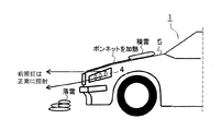
降雪下において車両が停車、駐車或いは徐行している場合等には、図13に示すように車両101のボンネット105上に雪が堆積し、この堆積した雪が前照灯104の前方へと垂れ下がり、この垂れ下がった雪(雪庇)が前照灯104からの出射光を遮るという不具合が発生する。
When the vehicle is stopped, parked or slowed down under snowfall, as shown in FIG. 13, snow accumulates on the
ところで、特許文献1には、フロントガラスに積もった雪によってワイパーの動作が阻害されないように、エンジン及び排気マニホールドの略上方のボンネット裏面に集熱器を配置するとともに、フロントガラスの下方に配置されたパネルヒータと集熱器及びタンクとを配管で接続して閉ループを構成し、集熱器においてエンジンと排気マニホールドの熱によって冷却水を加熱し、この加熱された冷却水をパネルヒータに導いてフロントガラスを加熱し、フロントガラス上に堆積した雪を冷却水の熱によって溶かすようにした融雪構造が提案されている。
By the way, in
又、特許文献2には、車両のボンネットや屋根に配管を取り回し、ラジエータからの温水を小型ポンプによって配管に循環させることによって、ボンネットや屋根に堆積した雪を溶かす融雪構造が提案されている。
特許文献1,2において提案された融雪構造は、エンジンやラジエータ等の熱源からの熱によって雪を溶かすものであるが、何れも熱媒体として冷却水を用いるため、この冷却水を循環させる配管や循環ポンプが必要となり、このために構造が複雑化してコストアップを招くという問題がある。
The snow melting structure proposed in
本発明は上記問題に鑑みてなされたもので、その目的とする処は、車両の外形を形成する車体パネルの一部を構成するボンネットやサイドパネル上に堆積した雪を簡単な構成で溶かして機能低下を防ぐことができる車両用前照灯を提供することにある。 The present invention has been made in view of the above problems, and the object of the present invention is to melt the snow accumulated on the bonnet and the side panel constituting a part of the vehicle body panel forming the outer shape of the vehicle with a simple configuration. An object of the present invention is to provide a vehicular headlamp that can prevent functional degradation.
上記目的を達成するため、請求項1に記載の発明は、ハウジングとその前面開口部を覆うアウタレンズによって画成された灯室内に、走行ビーム用ランプ又はすれ違いビーム用ランプの少なくとも何れか一方を収容して成る車両用前照灯において、前記ハウジングには該ハウジングと一体的に構成された送気ダクトを配設し、該送気ダクトの吸気口を車両のエンジンルーム内の熱源に向けて開口させ、同送気ダクトの排気口を当該車両用前照灯の上方に位置する車体パネルの裏面に向けて開口させたことを特徴とする。 To achieve the above object, according to the first aspect of the present invention, at least one of a traveling beam lamp and a passing beam lamp is accommodated in a lamp chamber defined by an outer lens covering a housing and a front opening of the housing. In this vehicle headlamp, the housing is provided with an air supply duct integrally formed with the housing, and the intake port of the air supply duct is opened toward a heat source in the engine room of the vehicle. The exhaust port of the air supply duct is opened toward the back surface of the vehicle body panel located above the vehicle headlamp.
請求項2に記載の発明は、請求項1に記載の発明において、前記車体パネルの一部はボンネットとして構成されており、前記送気ダクトの排気口を前記ボンネットとその裏面に設けられた遮熱材との間の空間に向けて開口させたことを特徴とする。 According to a second aspect of the present invention, in the first aspect of the present invention, a part of the vehicle body panel is configured as a bonnet, and an exhaust port of the air supply duct is provided on the bonnet and a rear surface thereof. It is characterized by opening toward the space between the heat material.
請求項3に記載の発明は、請求項1又は2に記載の発明において、前記送気ダクトの吸気口を車両のエンジンの近傍に開口させるとともに、該送気ダクト内に送気ファンを設けたことを特徴とする。
The invention according to
請求項4に記載の発明は、請求項1又は2に記載に発明において、前記送気ダクトの吸気口を車両のラジエータファンに向けて開口させたことを特徴とする。 According to a fourth aspect of the present invention, in the first or second aspect of the present invention, the intake port of the air supply duct is opened toward a radiator fan of a vehicle.
請求項5に記載の発明は、請求項1又は2に記載の発明において、前記送気ダクトの吸気口を車両のラジエータフード内に開口させるとともに、該送気ダクト内に送気ファンを設けたことを特徴とする。 According to a fifth aspect of the present invention, in the first or second aspect of the present invention, an air inlet of the air supply duct is opened in a radiator hood of the vehicle, and an air supply fan is provided in the air supply duct. It is characterized by that.
本発明によれば、熱源としてエンジンルーム内のエンジンやラジエータを用い、この熱源によって加熱された空気を送気ダクトの吸気口から該送気ダクト内に取り込んで排気口から車体パネル(ボンネットやサイドパネル)の裏面に向けて吹き付けるようにしたため、車体パネル(ボンネットやサイドパネル)が裏面側から加熱され、該車体パネル(ボンネットやサイドパネル)上に堆積した雪が溶けて落下する。このため、車体パネル(ボンネットやサイドパネル)上に堆積した雪が車両用前照灯の前方へと垂れ下がって該車両用前照灯からの出射光を遮ることがなく、車両用前照灯の機能が阻害されるという不具合の発生が防がれる。そして、本発明では、熱媒体として冷却水等の液体ではなく、気体としての空気を用いるために配管や循環ポンプが不要となり、車両用前照灯に送気ダクトを一体的に設けるだけの簡単な構成で前記効果を得ることができ、構造の複雑化や大幅なコストアップを招くことがない。そして、送気ダクトを車両用前照灯のハウジングと一体化したため、より一層の構造単純化とコストダウンを図ることができる。 According to the present invention, an engine or a radiator in an engine room is used as a heat source, and air heated by the heat source is taken into the air supply duct from the intake port of the air supply duct, and the vehicle body panel (bonnet or side Since the vehicle body panel (bonnet or side panel) is heated from the back surface side, the snow accumulated on the vehicle body panel (bonnet or side panel) melts and falls. For this reason, the function of the vehicle headlamp is such that the snow accumulated on the vehicle body panel (bonnet or side panel) hangs down to the front of the vehicle headlamp and does not block the light emitted from the vehicle headlamp. It is possible to prevent the occurrence of a malfunction that is hindered. In the present invention, since air as a gas is used instead of a liquid such as cooling water as a heat medium, piping and a circulation pump are not necessary, and an air supply duct is simply provided integrally with a vehicle headlamp. The above-described effect can be obtained with a simple configuration, and the structure is not complicated and the cost is not significantly increased. Further, since the air supply duct is integrated with the housing of the vehicle headlamp, the structure can be further simplified and the cost can be further reduced.
以下に本発明の実施の形態を添付図面に基づいて説明する。 Embodiments of the present invention will be described below with reference to the accompanying drawings.
<実施の形態1>
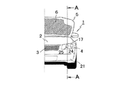
図1は本発明の実施の形態1に係る車両用前照灯を備える車両の半裁正面図、図2は図1のA−A線断面図、図3は同車両のエンジンルームの半裁平面図、図4は図3のA−A線断面図、図5は本発明の実施の形態1に係る車両用前照灯における送気ダクトの吸気口と排気口の開口状態を示す部分斜視図、図6(a),(b)は送気ダクトの構成例を示す部分断面図、図7(a),(b)は同送気ダクトの別構成例を示す部分断面図である。
<
FIG. 1 is a half-cut front view of a vehicle including a vehicle headlamp according to
図1に示す車両1は、車体の前部左右に本発明に係る前照灯4(図1には一方のみ図示)を備えている。ここで、左右の各前照灯4の基本構成は同じであるため、以下、一方の前照灯4についてのみ図示及び説明する。
A
各前照灯4は、図2に示すように、ハウジング12とその前面開口部を覆う透明なアウタレンズ22によって画成された灯室23内に、図1に示すように、車幅方向外側に配置された走行ビーム(ハイビーム)用ランプ24と、その内側に配置されたすれ違いビーム(ロービーム)用ランプ25等を収容して構成されている。
As shown in FIG. 2, each
ここで、すれ違いビーム用ランプ25の具体的な構成を図2に示すが、該すれ違いビーム陽ランプ25においては、固体光源(半導体発光素子である発光ダイオード(LED)やレーザー等)26がヒートシンク27に取り付けられており、この固体光源26の前方には、蛍光体28と投影レンズ29が順次配置されている。そして、このすれ違いビーム用ランプ25の周囲にはエクステンション30が配置されており、固体光源26は、ハウジング12の下面上に配置された電源31に給電用配線32を介して電気的に接続されている。
Here, a specific configuration of the
ところで、本発明に係る前照灯4を備える車両1は、図1に示すように、車体前部にエンジンルーム2を備えるとともに、フロントグリル3の左右に前照灯4(図1には一方のみ図示)を備えている。ここで、エンジンルーム2は、その上部が開閉可能なボンネット5(図1は開放状態を示す)によって覆われているが、このボンネット5の裏面には遮熱材6が設けられている。
By the way, as shown in FIG. 1, the
而して、図3に示すように、車両1のエンジンルーム2内には、前方からラジエータ7、ラジエータフード8、ラジエータファン9、エンジン10が順次配置されるとともに、左右の前照灯4(図3には一方のみ図示)の背面側には送気ダクト11がそれぞれ配置されている。ここで、左右の各送気ダクト11は、融雪構造を構成するものであって、図6に示すように、各前照灯4の樹脂製のハウジング12と一体化して構成されている。即ち、ハウジング12の外面の一部には、左右の縦リム12aが図6の紙面垂直方向に沿って互いに平行に一体に突設されており、図6(a)に示すように樹脂によってハウジング12とは別体に成形されたダクトカバー11Aを図6(b)に示すようにハウジング12の左右の縦リム12aに被せ、これをフック方式によって左右の縦リム12aに結合することによって送気ダクト11がハウジング12と一体的に形成される。ここで、ハウジング12の外面には、図7に示すように、縦リム11aに直交する横リム12bが立設されているが、この横リム12bが送気ダクト11内での空気(熱気)の流れを阻害しないように、図7(a)示すように、横リム12bの送気ダクト11内に臨む部位に複数(図示例では3つ)の孔13を形成したり、図7(b)に示すように、横リム12bの高さを縦リム12aの高さよりも低く(図示例では、縦リム12aの高さの1/2程度)にしている。
Thus, as shown in FIG. 3, a
そして、本実施の形態においては、図3及び図4に示すように、左右の各送気ダクト11(図3及び図4には一方のみ図示)に開口する吸気口11aは、熱源であるエンジン10の下部側方に向かって開口しており、各送気ダクト11内の吸気口11aに近い箇所には、図4に示すように、電磁ソレノイド14によって開閉される遮断弁15が設けられている。又、図4に示すように、各送気ダクト11の内部には送気ファン16がそれぞれ設けられている。
In the present embodiment, as shown in FIGS. 3 and 4, the
他方、図4及び図5に示すように、各送気ダクト11の上部には2つの排気口11b,11cがそれぞれ開口しており、一方の排気口11bは、ボンネット5とその裏面に設けられた遮熱材6との間に形成された空間Sに向かって開口し、他方の排気口11cは、サイドパネル17の裏面に向かって開口している。
On the other hand, as shown in FIGS. 4 and 5, two
ここで、本発明にッ駆る車両用前照灯4に設けられた融雪構造の制御システムの構成を図8に基づいて説明する。
Here, the configuration of the control system for the snow melting structure provided in the
図8は本実施の形態に係る融雪構造の制御システムを示すブロック図であり、制御手段であるECU18には記憶部18aが内蔵されており、このECU18の入力側には、融雪スイッチ19と降雪センサ20が接続され、出力側には、遮断弁15を駆動する電磁ソレノイド14と送気ファン16が接続されている。尚、融雪スイッチ19は、乗員が自らの意思によってON/OFF操作するものである。又、降雪センサ20は、例えばレーザー光線による反射の有無によって降雪を検知するものである。
FIG. 8 is a block diagram showing a control system for a snow melting structure according to the present embodiment. A
次に、本実施の形態に係る融雪構造の作用を図9に示すフローチャートを参照しながら以下に説明する。 Next, the operation of the snow melting structure according to the present embodiment will be described below with reference to the flowchart shown in FIG.
車両1に乗り込んだ乗員がエンジン10を始動し、そのとき、ボンネット5上やサイドパネル17上に雪が堆積している場合には、融雪スイッチ19をONする(図9のステップS1:Yes)。すると、ECU18は、融雪スイッチ19からの信号を受信して電磁ソレノイド14を駆動して遮断弁15を開くとともに、送気ファン16を駆動する(図9のステップS2)。このように遮断弁15が開かれて送気ファン16が駆動されると、熱源であるエンジン10の周囲の温度の高い空気(熱気)が送気ダクト11の吸気口11aから該送気ダクト11内に吸引される。そして、送気ダクト11内に吸引された温度の高い空気(熱気)は、送気ファン16によって排気口11b,11cへと送られ、一方の排気口11bから流出する空気(熱気)は、ボンネット5と遮熱材6との間の空間Sを流れる過程でボンネット5を裏面側から加熱し、他方の排気口11cから流出する空気(熱気)は、サイドパネル17の裏面に吹き付けられて該サイドパネル17を裏面側から加熱する。
An occupant who has entered the
上述のように、車両1のボンネット5とサイドパネル17が裏面側からそれぞれ加熱されることによって、これらのボンネット5上とサイドパネル17上に堆積した雪(正確には、ボンネット5とサイドパネル17の各表面に接する雪)が溶けるため、この堆積した雪が図10に示すようにボンネット5とサイドパネル17に沿って流れ落ちる。このため、ボンネット5上及びサイドパネル17上に堆積した雪が前照灯4の前方へと垂れ下がって該前照灯4からの出射光を遮ることがなく、前照灯4の機能が阻害されるという不具合の発生が防がれる。そして、本実施の形態では、熱媒体として冷却水等の液体ではなく、気体としての空気を用いるために配管や循環ポンプが不要となり、エンジンルーム2内に送気ダクト11を設けるだけの簡単な構成で前記効果を得ることができ、構造の複雑化や大幅なコストアップを招くことがない。尚、エンジン10の周囲の雰囲気温度は、77℃程度である。
As described above, the
又、本実施の形態では、送気ダクト11を前照灯4のハウジング12と一体化したため、より一層の構造単純化とコストダウンを図ることができる。そして、図7に示すように、送気ダクト11の一部を構成する縦リム12aを前照灯4のハウジング12に一体に立設すれば、該縦リム12aによってハウジング12の強度と剛性が高められるという効果も得られる。
In the present embodiment, since the
他方、乗員によって融雪スイッチ19がONされていない場合(図9のステップS1:No)であっても、降雪センサ20によって降雪が検知された場合(図9のステップS3:Yes)には、降雪センサ20からの信号を受信したECU18は、融雪の必要性があるものと判断して電磁ソレノイド14を駆動して遮断弁15を開くとともに、送気ファン16を駆動する(図9のステップS2)。すると、前述と同様に車両1のボンネット5とサイドパネル17が裏面側からそれぞれ加熱され、これらのボンネット5上とサイドパネル17上に堆積した雪が溶けて落下する。
On the other hand, even if the snow melting switch 19 is not turned on by the occupant (step S1: No in FIG. 9), if the snowfall sensor 20 detects snowfall (step S3: Yes in FIG. 9), the snowfall The
尚、車両1において、図3に示すように、バンパー21が前照灯4の前端よりも前方へ突出している場合には、このバンパー21上に雪が堆積して前記と同様の問題が発生するが、このような場合においては送気ダクト11の排出口(不図示)をバンパー21の上部裏面に向けて開口させることによってバンパー21を裏面側から加熱し、該バンパー21上に堆積した雪を溶かすことができる。
In the
<実施の形態2>
次に、本発明の実施の形態2を図11に基づいて説明する。
<
Next, a second embodiment of the present invention will be described with reference to FIG.
図11は本発明の実施の形態2に係る車両用前照灯に設けられた融雪構造を示す車両のエンジンルームの半裁平面図であり、本図においては、図3に示したものと同一要素には同一符号を付しており、以下、これらについての再度の説明は省略する。 FIG. 11 is a half plan view of a vehicle engine room showing a snow melting structure provided in a vehicle headlamp according to a second embodiment of the present invention. In FIG. 11, the same elements as those shown in FIG. Are denoted by the same reference numerals, and a repetitive description thereof will be omitted.
本実施の形態は、送気ダクト11の吸気口11aをラジエータファン9に向けて開口させたことを特徴としており、他の構成は前記実施の形態1のそれと同じである。但し、本実施の形態では、実施の形態1における送気ファン16は不要である。
The present embodiment is characterized in that the
而して、本実施の形態においては、ラジエータ7で高温のエンジン冷却水との間で熱交換して温度の高くなった空気(熱気)が送気ダクト11の吸気口11aから該送気ダクト11内に吸引され、前記実施の形態1と同様に、送気ダクト11から排出される温度の高い空気(熱気)によってボンネット5とサイドパネル17が裏側からそれぞれ加熱されるため、これらのボンネット5上とサイドパネル17上に堆積した雪が溶けて図10に示すように落下する。このため、ボンネット5上及びサイドパネル17上に堆積した雪が前照灯4の前方へと垂れ下がって該前照灯4からの出射光を遮ることがなく、前照灯4の機能が阻害されるという不具合の発生が防がれる。尚、ラジエータファン9を通過する空気の温度は、82℃程度の高い値を示す。
Thus, in the present embodiment, air (hot air) whose temperature has been increased by exchanging heat with the high-temperature engine cooling water by the
<実施の形態3>
次に、本発明の実施の形態3を図12に基づいて説明する。
<
Next,
図12は本発明の実施の形態3に係る車両用前照灯に設けられた融雪構造を示す車両のエンジンルームの半裁平面図であり、本図においても、図3に示したものと同一要素には同一符号を付しており、以下、これらについての再度の説明は省略する。
FIG. 12 is a half plan view of the engine room of the vehicle showing the snow melting structure provided in the vehicle headlamp according to
本実施の形態は、送気ダクト11をラジエータフード8に接続し、該送気ダクト11の吸気口11aをラジエータフード8内に開口させたことを特徴としており、他の構成は前記実施の形態1のそれと同じである。
The present embodiment is characterized in that the
而して、本実施の形態においては、ラジエータ7で高温のエンジン冷却水との間で熱交換して温度の高くなった空気(熱気)がラジエータフード8内に開口する送気ダクト11の吸気口11aから該送気ダクト11内に吸引され、前記実施の形態1と同様に、送気ダクト11から排出される温度の高い空気(熱気)によってボンネット5とサイドパネル17が裏側からそれぞれ加熱されるため、これらのボンネット5上とサイドパネル17上に堆積した雪が溶けて図10に示すように落下する。このため、前記実施の形態1,2と同様に、ボンネット5上及びサイドパネル17上に堆積した雪が前照灯4の前方へと垂れ下がって該前照灯4からの出射光を遮ることがなく、前照灯4の機能が阻害されるという不具合の発生が防がれる。
Thus, in the present embodiment, air (hot air) whose temperature has been increased by exchanging heat with the high-temperature engine cooling water in the
1 車両
2 エンジンルーム
3 フロントグリル
4 前照灯
5 ボンネット(車体パネル)
6 遮熱材
7 ラジエータ(熱源)
8 ラジエータフード
9 ラジエータファン
10 エンジン(熱源)
11 送気ダクト
11A ダクトカバー
11a 送気ダクトの吸気口
11b,11c 送気ダクトの排気口
12 前照灯のハウジング
12a ハウジングの縦リム
12b ハウジングの横リム
13 横リムの孔
14 電磁ソレノイド
15 遮断弁
16 送気ファン
17 サイドパネル(車体パネル)
18 ECU
19 融雪スイッチ
20 降雪センサ
21 バンパー
22 アウタレンズ
23 灯室
24 走行ビーム用ランプ
25 すれ違いビーム用ランプ
26 固体光源
27 ヒートシンク
28 蛍光体
29 投影レンズ
30 エクステンション
31 電源
32 給電用配線
S ボンネットと遮熱材との間の空間
1
6
8
DESCRIPTION OF
18 ECU
DESCRIPTION OF SYMBOLS 19 Snow-melting switch 20
Claims (5)
前記ハウジングには該ハウジングと一体的に構成された送気ダクトを配設し、該送気ダクトの吸気口を車両のエンジンルーム内の熱源に向けて開口させ、同送気ダクトの排気口を当該車両用前照灯の上方に位置する車体パネルの裏面に向けて開口させたことを特徴とする車両用前照灯。 In a vehicle headlamp configured to house at least one of a traveling beam lamp or a low beam lamp in a lamp chamber defined by an outer lens covering a housing and a front opening thereof,
The housing is provided with an air supply duct configured integrally with the housing, the air intake duct is opened toward a heat source in the engine room of the vehicle, and the air discharge duct has an exhaust port. A vehicle headlamp having an opening toward a back surface of a vehicle body panel positioned above the vehicle headlamp.
The vehicle headlamp according to claim 1 or 2, wherein an intake port of the air supply duct is opened in a radiator hood of the vehicle, and an air supply fan is provided in the air supply duct.
Priority Applications (1)
| Application Number | Priority Date | Filing Date | Title |
|---|---|---|---|
| JP2015244027A JP2017111908A (en) | 2015-12-15 | 2015-12-15 | Vehicle headlamp |
Applications Claiming Priority (1)
| Application Number | Priority Date | Filing Date | Title |
|---|---|---|---|
| JP2015244027A JP2017111908A (en) | 2015-12-15 | 2015-12-15 | Vehicle headlamp |
Publications (1)
| Publication Number | Publication Date |
|---|---|
| JP2017111908A true JP2017111908A (en) | 2017-06-22 |
Family
ID=59081396
Family Applications (1)
| Application Number | Title | Priority Date | Filing Date |
|---|---|---|---|
| JP2015244027A Pending JP2017111908A (en) | 2015-12-15 | 2015-12-15 | Vehicle headlamp |
Country Status (1)
| Country | Link |
|---|---|
| JP (1) | JP2017111908A (en) |
Cited By (2)
| Publication number | Priority date | Publication date | Assignee | Title |
|---|---|---|---|---|
| CN109484161A (en) * | 2017-09-11 | 2019-03-19 | 劳士领汽车集团 | The air valve apparatus with integrated optical conductor for motor vehicle |
| JP2019220321A (en) * | 2018-06-19 | 2019-12-26 | 株式会社クボタ | Operating machine |
-
2015
- 2015-12-15 JP JP2015244027A patent/JP2017111908A/en active Pending
Cited By (4)
| Publication number | Priority date | Publication date | Assignee | Title |
|---|---|---|---|---|
| CN109484161A (en) * | 2017-09-11 | 2019-03-19 | 劳士领汽车集团 | The air valve apparatus with integrated optical conductor for motor vehicle |
| CN109484161B (en) * | 2017-09-11 | 2023-12-15 | 劳士领汽车欧洲公司 | Valve system with integrated light guide for motor vehicles |
| JP2019220321A (en) * | 2018-06-19 | 2019-12-26 | 株式会社クボタ | Operating machine |
| JP7004413B2 (en) | 2018-06-19 | 2022-02-10 | 株式会社クボタ | Working machine |
Similar Documents
| Publication | Publication Date | Title |
|---|---|---|
| KR101796115B1 (en) | Head lamp assembly and vehicle having the same | |
| TWI527718B (en) | Vehicle headlight | |
| CN108916818A (en) | The anti-device that hazes, car light, automobile and the anti-control method that hazes | |
| US20180170247A1 (en) | Lamp assembly with grille lighting function | |
| US10634308B2 (en) | Lighting device for a motor vehicle | |
| JP2013152852A (en) | Vehicular lamp | |
| US8967842B2 (en) | Lamp condensation reduction system | |
| JP2017111908A (en) | Vehicle headlamp | |
| US20060104074A1 (en) | Vehicle body | |
| CN114543047A (en) | Projection device, anti-fog and anti-fog method thereof, lighting device and transportation tool | |
| JP2010170905A (en) | Cooling device for vehicular lighting fixture | |
| JP4455123B2 (en) | Vehicle headlight cooling system | |
| KR101936861B1 (en) | Air venting apparatus for lamp module of an automobile | |
| JP2018100011A (en) | Freezing prevention device for vehicle headlamp | |
| EP3584498B1 (en) | Vehicular lamp | |
| JP2006079881A (en) | Headlamp system | |
| JP2013152896A (en) | Vehicular lamp | |
| KR20100122642A (en) | Head lamp apparatus | |
| RU2706627C1 (en) | Vehicle cooling assembly and vehicle | |
| JP2018098087A (en) | Heat radiation structure of vehicular lighting | |
| JP4548252B2 (en) | Vehicle lighting device | |
| JP6960746B2 (en) | Heat dissipation structure of vehicle lighting equipment | |
| KR20140020655A (en) | Apparatus for cooling lamp module of an automobile | |
| JP2017191638A (en) | Vehicle lighting | |
| JP2017111923A (en) | Vehicle headlamp |