JP2017115991A - トルク伝達装置 - Google Patents
トルク伝達装置 Download PDFInfo
- Publication number
- JP2017115991A JP2017115991A JP2015252260A JP2015252260A JP2017115991A JP 2017115991 A JP2017115991 A JP 2017115991A JP 2015252260 A JP2015252260 A JP 2015252260A JP 2015252260 A JP2015252260 A JP 2015252260A JP 2017115991 A JP2017115991 A JP 2017115991A
- Authority
- JP
- Japan
- Prior art keywords
- sheet material
- rotating body
- pair
- side end
- torque
- Prior art date
- Legal status (The legal status is an assumption and is not a legal conclusion. Google has not performed a legal analysis and makes no representation as to the accuracy of the status listed.)
- Granted
Links
Images


Classifications
-
- F—MECHANICAL ENGINEERING; LIGHTING; HEATING; WEAPONS; BLASTING
- F16—ENGINEERING ELEMENTS AND UNITS; GENERAL MEASURES FOR PRODUCING AND MAINTAINING EFFECTIVE FUNCTIONING OF MACHINES OR INSTALLATIONS; THERMAL INSULATION IN GENERAL
- F16F—SPRINGS; SHOCK-ABSORBERS; MEANS FOR DAMPING VIBRATION
- F16F15/00—Suppression of vibrations in systems; Means or arrangements for avoiding or reducing out-of-balance forces, e.g. due to motion
- F16F15/10—Suppression of vibrations in rotating systems by making use of members moving with the system
- F16F15/12—Suppression of vibrations in rotating systems by making use of members moving with the system using elastic members or friction-damping members, e.g. between a rotating shaft and a gyratory mass mounted thereon
- F16F15/121—Suppression of vibrations in rotating systems by making use of members moving with the system using elastic members or friction-damping members, e.g. between a rotating shaft and a gyratory mass mounted thereon using springs as elastic members, e.g. metallic springs
- F16F15/123—Wound springs
- F16F15/1232—Wound springs characterised by the spring mounting
-
- F—MECHANICAL ENGINEERING; LIGHTING; HEATING; WEAPONS; BLASTING
- F16—ENGINEERING ELEMENTS AND UNITS; GENERAL MEASURES FOR PRODUCING AND MAINTAINING EFFECTIVE FUNCTIONING OF MACHINES OR INSTALLATIONS; THERMAL INSULATION IN GENERAL
- F16F—SPRINGS; SHOCK-ABSORBERS; MEANS FOR DAMPING VIBRATION
- F16F15/00—Suppression of vibrations in systems; Means or arrangements for avoiding or reducing out-of-balance forces, e.g. due to motion
- F16F15/10—Suppression of vibrations in rotating systems by making use of members moving with the system
- F16F15/12—Suppression of vibrations in rotating systems by making use of members moving with the system using elastic members or friction-damping members, e.g. between a rotating shaft and a gyratory mass mounted thereon
- F16F15/131—Suppression of vibrations in rotating systems by making use of members moving with the system using elastic members or friction-damping members, e.g. between a rotating shaft and a gyratory mass mounted thereon the rotating system comprising two or more gyratory masses
- F16F15/133—Suppression of vibrations in rotating systems by making use of members moving with the system using elastic members or friction-damping members, e.g. between a rotating shaft and a gyratory mass mounted thereon the rotating system comprising two or more gyratory masses using springs as elastic members, e.g. metallic springs
-
- F—MECHANICAL ENGINEERING; LIGHTING; HEATING; WEAPONS; BLASTING
- F16—ENGINEERING ELEMENTS AND UNITS; GENERAL MEASURES FOR PRODUCING AND MAINTAINING EFFECTIVE FUNCTIONING OF MACHINES OR INSTALLATIONS; THERMAL INSULATION IN GENERAL
- F16F—SPRINGS; SHOCK-ABSORBERS; MEANS FOR DAMPING VIBRATION
- F16F15/00—Suppression of vibrations in systems; Means or arrangements for avoiding or reducing out-of-balance forces, e.g. due to motion
- F16F15/10—Suppression of vibrations in rotating systems by making use of members moving with the system
- F16F15/12—Suppression of vibrations in rotating systems by making use of members moving with the system using elastic members or friction-damping members, e.g. between a rotating shaft and a gyratory mass mounted thereon
- F16F15/121—Suppression of vibrations in rotating systems by making use of members moving with the system using elastic members or friction-damping members, e.g. between a rotating shaft and a gyratory mass mounted thereon using springs as elastic members, e.g. metallic springs
- F16F15/123—Wound springs
- F16F15/1232—Wound springs characterised by the spring mounting
- F16F15/12346—Set of springs, e.g. springs within springs
Landscapes
- Engineering & Computer Science (AREA)
- General Engineering & Computer Science (AREA)
- Physics & Mathematics (AREA)
- Acoustics & Sound (AREA)
- Aviation & Aerospace Engineering (AREA)
- Mechanical Engineering (AREA)
- Springs (AREA)
- Mechanical Operated Clutches (AREA)
Abstract
Description
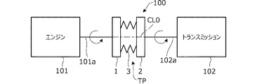
(1)トルク伝達装置100は、互いに同一の軸線CL0を中心にそれぞれ回転可能に設けられた第1回転体1および第2回転体2と、第1回転体1と第2回転体2との間のトルク伝達経路TPに配置され、第1回転体1および第2回転体2のいずれか一方からのトルクを第1回転体1および第2回転体2のいずれか他方に伝達するとともに、第1回転体1と第2回転体2との間のトルク変動を吸収するばね3と、ばね3の端部を保持する保持部411,421,431を一端面に有するシート材4(41〜43)とを備える(図3)。第1回転体1は、シート材4を周方向に移動可能に収容する収容部50を有し、収容部50は、シート材4の径方向外側への移動を規制する外周面51と、シート材4の周方向および径方向の移動を規制する凹曲面状の側端面53,54とを有する(図4)。第2回転体2は、径方向に突出する突出部23を有し、突出部23は、シート材4の周方向および径方向の移動を規制する凹曲面状の側端面25,26を有する(図3)。シート材4は、収容部50の周方向両端部に配置された一対のシート材41,42を含み、一対のシート材41,42は、ばね3と収容部50の側端面53,54および突出部23の側端面25,26との間に、収容部50の側端面53,54および突出部23の側端面25,26に対して接離可能に設けられる(図3)。一対のシート材41,42は、保持部411,421の反対側の他端面に、収容部50の側端面53,54および突出部23の側端面25,26に転動可能に接触する凸曲面状の接触面412,422をそれぞれ有する(図3)。
上記実施形態は種々の形態に変形することができる。以下、変形例について説明する。上記実施形態では、初期状態において、一対のばね3の中心線CL31,CL32の交点P30が基準線L3よりも径方向内側に位置するように、中間シート材43の座面角度βを0°より大きく設定したが、座面角度βの値はこれに限らない。例えば座面角度βを0°にしてもよい。この場合、初期状態で交点P30が基準線L3上に位置するようになる。上記実施形態では、ばね3を不等ピッチに構成したが、等ピッチに構成してもよい。すなわち、ばね3の長さ方向にわたってばね3の密度が一定となるようにしてもよい。
Claims (5)
- 互いに同一の軸線を中心にそれぞれ回転可能に設けられた第1回転体および第2回転体と、
前記第1回転体と前記第2回転体との間のトルク伝達経路に配置され、前記第1回転体および前記第2回転体のいずれか一方からのトルクを前記第1回転体および前記第2回転体のいずれか他方に伝達するとともに、前記第1回転体と前記第2回転体との間のトルク変動を吸収する弾性体と、
前記弾性体の端部を保持する保持部を一端面に有するシート材と、を備え、
前記第1回転体は、前記シート材を周方向に移動可能に収容する収容部であって、前記シート材の径方向外側への移動を規制する外周面と、前記シート材の周方向および径方向の移動を規制する凹曲面状の側端面とを有する収容部を有し、
前記第2回転体は、径方向に突出する突出部であって、前記シート材の周方向および径方向の移動を規制する凹曲面状の側端面を有する突出部を有し、
前記シート材は、前記収容部の周方向両端部に配置された一対のシート材であって、前記弾性体と前記収容部の前記側端面および前記突出部の前記側端面との間に、前記収容部の前記側端面および前記突出部の前記側端面に対して接離可能に設けられた一対のシート材を含み、
前記一対のシート材は、前記保持部の反対側の他端面に、前記収容部の前記側端面および前記突出部の前記側端面に転動可能に接触する凸曲面状の接触面をそれぞれ有することを特徴とするトルク伝達装置。 - 請求項1に記載のトルク伝達装置において、
前記シート材は、前記一対のシート材の間に配置される中間シート材をさらに有し、
前記弾性体は、前記一対のシート材と前記中間シート材との間にそれぞれ介装された一対のばねを有することを特徴とするトルク伝達装置。 - 請求項2に記載のトルク伝達装置において、
前記一対のばねは、前記中間シート材に作用する遠心力が0の初期状態で、前記一対のばねの中心線同士の交点が前記一対のシート材の前記保持部の中心部同士を接続する基準線よりも径方向内側に位置するように傾斜して配置されることを特徴とするトルク伝達装置。 - 請求項2または3に記載のトルク伝達装置において、
前記一対のばねは、前記一対のシート材から前記中間シート材に向かうほど、ばねの単位長さ当たりの密度が大きくなるように形成されることを特徴とするトルク伝達装置。 - 請求項2〜4のいずれか1項に記載のトルク伝達装置において、
前記中間シート材の外周面は、前記収容部の前記外周面よりも曲率半径が小さい円弧状を呈することを特徴とするトルク伝達装置。
Priority Applications (3)
| Application Number | Priority Date | Filing Date | Title |
|---|---|---|---|
| JP2015252260A JP6293113B2 (ja) | 2015-12-24 | 2015-12-24 | トルク伝達装置 |
| US15/379,366 US10151372B2 (en) | 2015-12-24 | 2016-12-14 | Torque transmission apparatus |
| CN201611189337.7A CN107013625B (zh) | 2015-12-24 | 2016-12-21 | 转矩传递装置 |
Applications Claiming Priority (1)
| Application Number | Priority Date | Filing Date | Title |
|---|---|---|---|
| JP2015252260A JP6293113B2 (ja) | 2015-12-24 | 2015-12-24 | トルク伝達装置 |
Publications (2)
| Publication Number | Publication Date |
|---|---|
| JP2017115991A true JP2017115991A (ja) | 2017-06-29 |
| JP6293113B2 JP6293113B2 (ja) | 2018-03-14 |
Family
ID=59086204
Family Applications (1)
| Application Number | Title | Priority Date | Filing Date |
|---|---|---|---|
| JP2015252260A Expired - Fee Related JP6293113B2 (ja) | 2015-12-24 | 2015-12-24 | トルク伝達装置 |
Country Status (3)
| Country | Link |
|---|---|
| US (1) | US10151372B2 (ja) |
| JP (1) | JP6293113B2 (ja) |
| CN (1) | CN107013625B (ja) |
Families Citing this family (2)
| Publication number | Priority date | Publication date | Assignee | Title |
|---|---|---|---|---|
| FR3090776B1 (fr) * | 2018-12-20 | 2020-12-18 | Valeo Embrayages | Dispositif de transmission de couple avec des ressorts en série et système de transmission de couple comprenant un tel dispositif |
| EP3899317B1 (fr) * | 2018-12-20 | 2023-01-04 | Valeo Embrayages | Dispositif de transmission de couple avec des ressorts en serie et systeme de transmission de couple comprenant un tel dispositif |
Citations (5)
| Publication number | Priority date | Publication date | Assignee | Title |
|---|---|---|---|---|
| JPS6081520A (ja) * | 1983-10-12 | 1985-05-09 | Shiyouyou Giken Kogyo Kk | 緩衝伝動装置 |
| JPS63103033U (ja) * | 1986-12-23 | 1988-07-04 | ||
| JPH0545257U (ja) * | 1991-11-25 | 1993-06-18 | 株式会社大金製作所 | ダンパーデイスク |
| US6047804A (en) * | 1997-08-01 | 2000-04-11 | Mannesmann Sachs Ag | Torsional vibration damper |
| JP2014111959A (ja) * | 2012-12-05 | 2014-06-19 | Toyota Motor Corp | 捩り振動減衰装置 |
Family Cites Families (4)
| Publication number | Priority date | Publication date | Assignee | Title |
|---|---|---|---|---|
| DE8522888U1 (de) * | 1985-08-08 | 1985-10-10 | Fichtel & Sachs Ag, 8720 Schweinfurt | Progressive Druckfeder in Kupplungsscheiben |
| US5377560A (en) * | 1992-08-03 | 1995-01-03 | Fichtel & Sachs Ag | Double-mass flywheel |
| JP2015086965A (ja) | 2013-10-31 | 2015-05-07 | 株式会社エクセディ | フライホイール組立体 |
| CN204025526U (zh) * | 2014-07-29 | 2014-12-17 | 郑州宇通客车股份有限公司 | 弹簧减振机构及使用该弹簧减振机构的扭转减振器 |
-
2015
- 2015-12-24 JP JP2015252260A patent/JP6293113B2/ja not_active Expired - Fee Related
-
2016
- 2016-12-14 US US15/379,366 patent/US10151372B2/en active Active
- 2016-12-21 CN CN201611189337.7A patent/CN107013625B/zh not_active Expired - Fee Related
Patent Citations (5)
| Publication number | Priority date | Publication date | Assignee | Title |
|---|---|---|---|---|
| JPS6081520A (ja) * | 1983-10-12 | 1985-05-09 | Shiyouyou Giken Kogyo Kk | 緩衝伝動装置 |
| JPS63103033U (ja) * | 1986-12-23 | 1988-07-04 | ||
| JPH0545257U (ja) * | 1991-11-25 | 1993-06-18 | 株式会社大金製作所 | ダンパーデイスク |
| US6047804A (en) * | 1997-08-01 | 2000-04-11 | Mannesmann Sachs Ag | Torsional vibration damper |
| JP2014111959A (ja) * | 2012-12-05 | 2014-06-19 | Toyota Motor Corp | 捩り振動減衰装置 |
Also Published As
| Publication number | Publication date |
|---|---|
| JP6293113B2 (ja) | 2018-03-14 |
| CN107013625B (zh) | 2018-11-30 |
| US10151372B2 (en) | 2018-12-11 |
| US20170184178A1 (en) | 2017-06-29 |
| CN107013625A (zh) | 2017-08-04 |
Similar Documents
| Publication | Publication Date | Title |
|---|---|---|
| JP6293111B2 (ja) | トルク伝達装置 | |
| CN103261733B (zh) | 离心力摆装置 | |
| JP2018504565A (ja) | 自動車の動力伝達チェーンに対する振動減衰装置 | |
| EP3163117A1 (en) | Damper device | |
| US20180231097A1 (en) | Blade-type torsional damper | |
| JP6293113B2 (ja) | トルク伝達装置 | |
| US10533629B2 (en) | Centrifugal pendulum damper and torque transmission device | |
| JP5772983B2 (ja) | 捩り振動減衰装置 | |
| JP6309409B2 (ja) | 等速ジョイント | |
| JP2006283828A (ja) | トリポード型等速自在継手 | |
| JP2021028521A (ja) | ダンパ装置 | |
| JP2006112495A (ja) | 等速ジョイント | |
| JP2014137079A (ja) | ダンパ装置 | |
| JP5030846B2 (ja) | 捩り振動低減装置 | |
| JP2017166656A (ja) | トルク伝達装置 | |
| CN112041590B (zh) | 离心摆 | |
| JP5742756B2 (ja) | 捩り振動減衰装置 | |
| JP6807253B2 (ja) | トルク伝達装置 | |
| JP6180993B2 (ja) | 無段変速機 | |
| JP2012013207A (ja) | トリポード型等速ジョイント | |
| JPH10325418A (ja) | 弾性軸継手 | |
| JP2007064324A (ja) | 等速自在継手 | |
| JP6875345B2 (ja) | センターベアリング | |
| JP2019019880A (ja) | ダンパ | |
| JP2018155379A (ja) | トリポード型等速自在継手 |
Legal Events
| Date | Code | Title | Description |
|---|---|---|---|
| A131 | Notification of reasons for refusal |
Free format text: JAPANESE INTERMEDIATE CODE: A131 Effective date: 20170919 |
|
| A521 | Request for written amendment filed |
Free format text: JAPANESE INTERMEDIATE CODE: A523 Effective date: 20170927 |
|
| TRDD | Decision of grant or rejection written | ||
| A01 | Written decision to grant a patent or to grant a registration (utility model) |
Free format text: JAPANESE INTERMEDIATE CODE: A01 Effective date: 20180206 |
|
| A61 | First payment of annual fees (during grant procedure) |
Free format text: JAPANESE INTERMEDIATE CODE: A61 Effective date: 20180213 |
|
| R150 | Certificate of patent or registration of utility model |
Ref document number: 6293113 Country of ref document: JP Free format text: JAPANESE INTERMEDIATE CODE: R150 |
|
| LAPS | Cancellation because of no payment of annual fees |