JP2017116165A - Water heater life diagnosis method - Google Patents
Water heater life diagnosis method Download PDFInfo
- Publication number
- JP2017116165A JP2017116165A JP2015250805A JP2015250805A JP2017116165A JP 2017116165 A JP2017116165 A JP 2017116165A JP 2015250805 A JP2015250805 A JP 2015250805A JP 2015250805 A JP2015250805 A JP 2015250805A JP 2017116165 A JP2017116165 A JP 2017116165A
- Authority
- JP
- Japan
- Prior art keywords
- water heater
- temperature
- score
- points
- heat exchanger
- Prior art date
- Legal status (The legal status is an assumption and is not a legal conclusion. Google has not performed a legal analysis and makes no representation as to the accuracy of the status listed.)
- Granted
Links
Images




Landscapes
- Heat-Pump Type And Storage Water Heaters (AREA)
Abstract
【課題】正確に温水器の寿命を判断する寿命診断方法を提供する。
【解決手段】温水器の様々な情報を取得し(ステップ1)、各情報に応じてあらかじめ定めた基準で得点を付与し(ステップ2)、得点の合計点により温水器の劣化を類推し、寿命を判断することにより(ステップ4)、正確に温水器の寿命を判断することができる。
【選択図】図3A life diagnosis method for accurately determining the life of a water heater is provided.
[Solution] Various information of the water heater is acquired (Step 1), a score is given according to a predetermined criterion according to each information (Step 2), and the deterioration of the water heater is inferred from the total score, By determining the lifetime (step 4), the lifetime of the water heater can be accurately determined.
[Selection] Figure 3
Description
ボイラ等の温水器の劣化を判断する温水器の寿命診断方法に関する。 The present invention relates to a life diagnosis method of a water heater for judging deterioration of a water heater such as a boiler.
蒸気ボイラおよび温水器は、ビルや病院,ホテル等の施設の暖房手段や給湯等に利用されている。温水器は法定耐用年数が定められておらず、温水器の交換時期を判断することは困難であった。温水器が故障すると、暖房や給湯が停止し、施設によっては営業に支障をきたす場合がある。そのため、温水器について、故障が発生する前に温水器の劣化を判断して寿命が近づいていることを検知し、温水器の交換時期を把握することが必要となる。 Steam boilers and water heaters are used for heating means and hot water supply for buildings, hospitals, hotels and other facilities. The water heater has no statutory useful life, and it is difficult to determine when to replace the water heater. When a water heater breaks down, heating and hot water supply are stopped, and depending on the facility, business may be hindered. For this reason, it is necessary to determine the deterioration of the water heater before the failure occurs, to detect that the life is approaching, and to grasp the replacement time of the water heater.
例えば従来から、燃焼用ファンの駆動モータに供給される電流とボイラ缶内圧力とを測定し、これらから使用蒸気量および使用熱量を演算してボイラの稼働状況を把握するボイラ用蒸気負荷分析装置があった(例えば、特許文献1参照)。 For example, conventionally, a steam load analyzer for a boiler that measures the current supplied to the drive motor of the combustion fan and the pressure in the boiler can, and calculates the amount of steam used and the amount of heat used to determine the operating status of the boiler. (For example, see Patent Document 1).
しかしながら、従来のボイラ用蒸気負荷分析装置は蒸気ボイラおよび温水器において、使用蒸気量および使用熱量を求める装置であるため、温水器の寿命である交換時期を正確に把握することが困難であった。 However, since the conventional steam load analyzer for boilers is a device for determining the amount of steam used and the amount of heat used in steam boilers and water heaters, it is difficult to accurately grasp the replacement time, which is the life of the water heater. .
本発明は、正確に温水器の寿命を判断することを目的とする。 An object of this invention is to determine the lifetime of a water heater correctly.
本発明の温水器の寿命診断方法は、温水器の排気ガスの温度,燃焼用ファンモータの振動,熱交換器内を循環する温水の圧力の温水器入口と出口における差圧,前記温水器の騒音,前記温水器の表面温度および付帯動力盤の温度を測定する工程と、前記温水器の排気ガスの温度,前記燃焼用ファンモータの振動,前記熱交換器内を循環する温水の圧力の温水器入口と出口における差圧,前記温水器の騒音,前記温水器の表面温度および前記付帯動力盤の温度それぞれについて劣化が少ないほど高くなる点数を付与する工程と、前記温水器に搭載されるマイコンについて新型であるほど高くなる点数を付与する工程と、前記温水器の使用年数に応じて使用年数が少ないほど高くなる点数を付与する工程と、前記点数を合計して合計点を求める工程と、前記合計点があらかじめ定めた基準値より低い場合に前記温水器の寿命であると診断する工程とを有することを特徴とする。 The water heater life diagnosis method of the present invention includes the temperature of the exhaust gas of the water heater, the vibration of the combustion fan motor, the difference in pressure of the hot water circulating in the heat exchanger at the inlet and outlet of the water heater, Measuring the noise, the surface temperature of the water heater and the temperature of the auxiliary power panel, the temperature of the exhaust gas of the water heater, the vibration of the combustion fan motor, the hot water pressure of the hot water circulating in the heat exchanger A step of assigning a higher point for less deterioration with respect to the differential pressure at the inlet and outlet, the noise of the water heater, the surface temperature of the water heater and the temperature of the auxiliary power panel, and a microcomputer mounted on the water heater The step of giving a higher score as the model is newer, the step of giving a higher score according to the number of years of use of the water heater, and a process for obtaining the total score by adding the points When, characterized in that a step of the total score is diagnosed with life of the water heater is lower than the predetermined reference value.
以上のように、温水器の様々な情報を取得し、各情報に応じてあらかじめ定めた基準で得点を付与し、得点の合計点により温水器の劣化を類推し、寿命を判断することにより、正確に温水器の寿命を判断することができる。 As described above, by acquiring various information on the water heater, assigning a score on a predetermined basis according to each information, analogizing the deterioration of the water heater by the total score, and judging the life, It is possible to accurately determine the life of the water heater.
まず、図1,図2を用いて、本発明の一実施形態における温水器と寿命の診断に用いる各種測定器との構成を説明する。
図1は各種情報を取得するための測定器と温水器との関係を例示する概略図、図2は取得した各種情報から寿命を判断する寿命診断装置の構成を例示する概略図である。
First, the configuration of a water heater and various measuring instruments used for life diagnosis in one embodiment of the present invention will be described with reference to FIGS.
FIG. 1 is a schematic diagram illustrating the relationship between a measuring instrument and a water heater for acquiring various types of information, and FIG. 2 is a schematic diagram illustrating the configuration of a life diagnosis apparatus that determines the lifetime from various types of acquired information.
温水器1には複数の測定器が接続され、各測定器において種々の情報が取得される。各測定器の一部は寿命診断装置2に接続されており、寿命診断装置2に取得した情報を送信する。寿命診断装置2は取得した各種の情報を保存する。残りの測定器が取得した情報は作業者が収集する。測定器としては、例えば以下のような機器を用いることができる。
A plurality of measuring devices are connected to the
温度測定器3は、温水器1の排気ガスを排出する煙道4に設けられ、排気ガスの温度を測定する。温度測定器3は煙道4内の排気ガスの温度を測定するために、煙道4内に温度測定部が配置されるように設けられ、寿命診断装置2に接続されて測定結果を寿命診断装置2に送信する。温度測定器3として、例えば、熱電対や測温抵抗体が用いられる。
The
速度計5および加速度計6は、温水器1の燃焼室18に空気を送風する燃焼用ファンモータ7に設けられ、燃焼用ファンモータ7の振動に伴う速度変化および加速度変化を測定する。速度計5および加速度計6は、燃焼用ファンモータ7の回転軸に対して直交する方向に設置される。速度計5および加速度計6は寿命診断装置2に接続されて測定結果を寿命診断装置2に送信する。
The
差圧計8は、給湯回路または循環・暖房回路の熱交換器内を循環する温水の圧力の温水器入口と出口における差圧を測定する。差圧計8は、給湯回路または循環・暖房回路における熱交換器入口9および熱交換器出口10それぞれに設けられ、熱交換器入口9および熱交換器出口10を流れる温水の水圧から差圧を測定する。差圧は熱交換器の閉塞の判断に用いることができる。給湯回路における熱交換器入口9および熱交換器出口10への差圧計設置が困難な場合、循環回路または暖房回路における熱交換器入口9および熱交換器出口10へ設けても良い。差圧計8は寿命診断装置2に接続されて測定された差圧を寿命診断装置2に送信する。
The
騒音計11は、温水器1のバーナ正面に設置され、温水器1が作動中の騒音を測定する。騒音計11の設置位置は、温水器1のバーナ正面に限らず、煙道4の正面等、あらかじめ定めた一定の場所に設置されても良い。騒音計11で得られた測定値は作業員により手動で記録され、例えば作業員により手動でPC15の記憶装置17に記録される。あるいは、騒音計11と寿命診断装置2とを接続し、測定結果を寿命診断装置2の記憶装置16に自動転送する構成としても良い。
The
サーモグラフィ12は、温水器1の本体および付帯動力盤13の放熱温度を赤外線撮影することにより測定する。サーモグラフィ12は、手動で温度を測定したい場所を撮影し、温水器1については、本体全面を撮影するようにする。サーモグラフィ12は、手動で温度を読取り作業員により手動で記憶される。例えば作業員により手動でPC15の記憶装置17に記録される。あるいは、サーモグラフィ12と寿命診断装置2とを接続し、測定結果を寿命診断装置2の記憶装置16に自動転送する構成としても良い。さらに、サーモグラフィ12内に赤外線写真を保存し、診断の際の参考資料としても良い。
The
電流計14は、付帯動力盤13の燃焼用ファンモータ7および燃料電磁弁に電流を供給する配線に接続され、燃焼用ファンモータ7および燃料電磁弁に供給される電流値を測定する。電流計14は配線を挟み込むことにより、配線を流れる電流の電流値を測定する構成とすることができる。電流計14は寿命診断装置2に接続されて測定結果を寿命診断装置2に送信する。
The
寿命診断装置2は、上記各測定結果である各種の一部の情報を取得し、測定結果を記録する記憶装置16を備える。作業者は、手動で温水器1に内蔵されるマイコンの情報や温水器1の使用年数、温水器1の型番等を情報としてPC15の記憶装置17に記憶する。作業者は収集した情報および寿命診断装置2が保存している情報を読み出して、各情報を劣化の度合いに応じた点数に換算し、温水器1の寿命を診断する。例えば、作業者はPC15等の記憶装置17に残りの測定器から収拾した情報を記録し、寿命診断装置2が保存している情報を記憶装置17に転送する。そして、PC15等を操作し、表計算ソフト等を用いて記憶装置17に保存された各温水器1の情報を点数に換算し、その合計点数から寿命を診断する。つまり、これら各種の情報それぞれについて、あらかじめ定めた基準に従い劣化の程度を表す点数に変換する。そしてこれらの点数の合計から温水器1の劣化を判断し、温水器1の寿命が近いか否かを診断する。あるいは、作業者は、残りの測定器が取得した情報を収集して手動で寿命診断装置2に入力し、寿命診断装置2があらかじめ定めた基準で各情報を点数換算し、寿命を診断することもできる。この場合、寿命診断装置2は、手動で情報を入力するためのキーボード等の入力装置(図示せず)を備える。また、各種の情報や変換された点数、診断結果等を記憶する記憶装置(図示せず)を備えることができる。さらに、点数への変換や寿命の診断を行うコンピュータ(図示せず)を搭載することもできる。また、寿命診断装置2を用いず、各測定器をPC15と接続し、測定結果の一部をPC15の記憶装置17に転送し、残りの測定結果を作業者が手動で記憶装置17に記憶する構成とすることもできる。
The
次に、図1〜図3を用いて温水器の寿命診断方法を説明する。
図3は本発明の温水器の寿命診断方法を示す概略フロー図である。
まず、寿命診断装置2は、各測定器で取得した情報を有線あるいは無線を介して取得する。手動で情報を寿命診断装置2に入力する必要がある場合は、作業者は手動で情報を寿命診断装置2に入力する。また、情報をPC15等の記憶装置17に入力する必要がある場合は、作業者は手動で情報を記憶装置17に入力する(図3のステップ1)。
Next, the lifetime diagnosis method of a water heater will be described with reference to FIGS.
FIG. 3 is a schematic flow chart showing the water heater life diagnosis method of the present invention.
First, the
次に、各種測定装置により測定した情報およびその他作業員が記録した各情報を、項目毎にあらかじめ定めた基準で点数に変換する。点数は、各項目での劣化の状況と測定値との関係に基づいて定められ、点数が高い程劣化の程度が低いとする。また、各項目は温水器1の劣化に与える影響を考慮して重み付けを付与される。上記の項目においては、温水器1の振動と熱交換器の差圧とが他の項目に比べて温水器1が劣化している時に顕著に測定結果に差がでるため、温水器1の振動と給湯回路または循環・暖房回路における熱交換器の差圧とに重み付けを付与しても良い。例えば、排気ガスの温度に10点、温水器1の振動に20点、給湯回路または循環・暖房回路における熱交換器の差圧に20点、温水器1の騒音に10点、温水器1の放熱に10点、動力盤13の放熱に10点、マイコンのバージョンに10点、温水器1の耐用年数に10点を付与する。各項目は劣化が進行している程点数が低くなる(図3のステップ2)。各項目における点数への変換方法については後述する。
Next, the information measured by the various measuring devices and the other information recorded by the workers are converted into points according to a predetermined criterion for each item. The score is determined based on the relationship between the state of deterioration in each item and the measured value, and the higher the score, the lower the degree of deterioration. Each item is given a weight in consideration of the influence on the deterioration of the
次に、各項目における点数を合計する。上記の例では配点の合計点は100点となる(図3のステップ3)。
最後に、合計点があらかじめ定めた所定の点数、例えば50点以下であるかどうか確認する(図3のステップ4)。合計点が所定の点数以下の場合、劣化が進行し、寿命が近く、交換時期であると診断し(図3のステップ5)、合計点が所定の点数より大きい場合、交換は不要であると診断する。点数の集計はエクセル等を使用し作業員が行う。以上の診断は作業者が行っても良いし、寿命診断装置2やPC15等のコンピュータが自動的に行っても良い(図3のステップ6)。
Next, the score in each item is totaled. In the above example, the total score is 100 points (
Finally, it is confirmed whether or not the total score is a predetermined score, for example, 50 or less (
以上のように、温水器1の劣化に伴って結果が変化する複数の項目の測定を行い、各項目の測定結果を劣化に対応する得点に変換し、複数の項目の合計点数から、総合的に温水器1の劣化を判断して温水器1の交換時期であるか否かを診断することにより、少ない項目での診断に比べて正確に診断できると共に、あらかじめ定めた基準で付与する点数により診断するため容易に温水器1の寿命を診断することが可能となる。
As described above, a plurality of items whose results change with the deterioration of the
以上のように、各工程の測定データを寿命診断装置が記録し、そのデータをもとに作業員が分析作業を行う。なお、以上の各工程をプログラムを実行することにより行っても良い。この場合、プログラムは寿命診断装置2またはPC15に搭載されるコンピュータにより実行される。また、記憶装置16または記憶装置17はコンピュータに読み込み可能な構成であり、プログラムが格納される。プログラムは、記憶装置16および記憶装置17に記憶された各種情報を読み込んで分析処理する。
As described above, the life diagnosis apparatus records the measurement data of each process, and the worker performs analysis work based on the data. Note that the above steps may be performed by executing a program. In this case, the program is executed by a computer mounted on the
次に、図1〜図7を用いて、図3のステップ2において各項目における測定結果を点数に変換する方法の例について説明する。
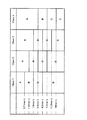
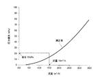
図4はISO10816−1における振動値判定基準を示す図、図5は24時間差圧を測定した例を示す図、図6は供給電流に対する温水器の循環ポンプの性能曲線を例示する図、図7は温水器が備える熱交換器能力グラフを例示する図である。
Next, an example of a method for converting the measurement result of each item into a score in
4 is a diagram illustrating vibration value determination criteria in ISO 10816-1, FIG. 5 is a diagram illustrating an example of measuring a differential pressure for 24 hours, FIG. 6 is a diagram illustrating a performance curve of a circulating pump of a water heater with respect to supply current, and FIG. FIG. 4 is a diagram illustrating a heat exchanger capacity graph included in the water heater.
まず、排気ガスの温度について、配点が10点である場合を例に説明する。
温水器1の運転時の排気ガスの温度を、温水器1の導入時つまり新品の状態での運転時の排気ガスの温度と比較する。温水器1の運転時とは、通常運転時または定格運転時である。温水器1の運転時の排気ガスの温度は劣化により温度が上昇するため、温度を測定することにより劣化を判断することができる。点数は、温水器1を導入した時に運転した時の排気ガスの温度を基準温度とする。運転時の排気ガスの温度が基準温度であれば10点とする。点数は、基準温度より6℃上回るごとに1点減点され、基準温度より60℃以上上回っていると0点とする。
First, the exhaust gas temperature will be described by taking as an example a case where there are 10 points.
The temperature of the exhaust gas during operation of the
次に、温水器1の振動について、配点が20点である場合を例に説明する。
温水器1の振動は劣化により大きくなるため、振動を測定することにより劣化を判断することができる。温水器1の振動については、速度計5の測定値および加速度計6の測定値それぞれに10点が配点される。速度計5の測定値はISO10816−1に準拠するゾーンに応じて点数に変換される。ISO10816−1では、温水器1の大きさおよび設置状態により4つのクラスに分けられる。また、図4に示すように、4つのクラスそれぞれにおいて、測定された速度に応じて4つのゾーンに分類される。そして、測定された速度が属するゾーンに応じて点数が付与され、測定された速度がゾーンAに入る場合は10点、ゾーンBに入る場合は5点、ゾーンCに入る場合は2点、ゾーンDに入る場合は0点とする。ISO10816−1ではclass1を「全体の構成要素の一部として組み込まれたエンジンや機械(15kW以下の汎用電動機等)」と定めており、温水器はこれに分類される。class1では測定された速度が0mm/s以上0.71mm/s未満の場合ゾーンAで10点、0.71mm/s以上1.80mm/s未満の場合ゾーンBで5点、1.80mm/s以上4.50mm/s未満の場合ゾーンCで2点、4.50mm/s以上の場合ゾーンDで0点となる。
Next, the vibration of the
Since the vibration of the
加速度については、測定された加速度に応じて4つのゾーンに分類される。そして、測定された加速度が属するゾーンに応じて点数が付与され、測定された加速度が、0G以上0.10G未満の場合はゾーンAとし10点、0.10G以上0.23G未満の場合はゾーンBとし5点、0.23G以上0.70G未満の場合はゾーンCとし2点、0.70G以上の場合はゾーンDとし0点とする。 The acceleration is classified into four zones according to the measured acceleration. A score is given according to the zone to which the measured acceleration belongs. If the measured acceleration is 0G or more and less than 0.10G, the zone A is 10 points, and if the measured acceleration is 0.10G or more and less than 0.23G, the zone is given. B is 5 points, and if it is 0.23G or more and less than 0.70G, it is set as zone C, and if it is 0.70G or more, it is set as zone D and 0 point.
次に、熱交換器の差圧について、配点が20点である場合を例に説明する。
熱交換器の閉塞を示す差圧は劣化により大きくなるため、差圧を測定することにより劣化を判断することができる。まず、差圧計8により、給湯回路または循環・暖房回路の熱交換器内を循環する温水の圧力の温水器入口と出口における差圧を一定時間連続的に測定する。このとき、給湯回路における熱交換器入口と出口を循環する温水の圧力の差圧を測定することが困難な場合、循環回路または暖房回路における熱交換器入口と出口を循環する温水の圧力の差圧を一定時間連続的に測定しても良い。例えば、図5に示すように24時間差圧を測定し、その最大値を熱交換器内での圧力損失として検出する。図5の例では差圧の最大値は22kPaとなる。
Next, the differential pressure of the heat exchanger will be described by taking as an example a case where there are 20 points.
Since the differential pressure indicating the blockage of the heat exchanger increases due to the deterioration, the deterioration can be determined by measuring the differential pressure. First, the
次に、電流計14で測定したる循環ポンプに供給される電流値を取得する。ここでは、電流値が5.1Aであったとする。そして、図6に示すような温水器1に搭載された循環ポンプの電流値と吐出し量との関係を示す性能曲線から、循環ポンプに供給される電流値に対応する循環ポンプから排出される給湯の吐出し量を求める。図6の例では、電流値5.1Aに対応する吐出し量は15m3/hとなる。
Next, the current value supplied to the circulation pump measured by the
その後、図7に示すような温水器1の熱交換器能力曲線から、循環する温水の流量である吐出し量に対する適正な差圧を算出する。検出した差圧が適正な差圧以下であれば20点とする。適正な差圧を超える場合の点数は、熱交換器の能力曲線から、設計上の最大流量が流れた場合の差圧を最大差圧として、最大差圧と適正差圧の間を20等分し、そこから検出した差圧の点数を判断する。検出した差圧が最大差圧の時0点とする。例えば、図7では、適正な差圧は15kPaであり、最大差圧は80kPaであるので、3.25kPa毎に1点減点する。21.5kPaの時18点、24.75kPaの時17点となり、検出した差圧は22kPaであるため、繰り下げて17点とする。
Thereafter, an appropriate differential pressure with respect to the discharge amount, which is the flow rate of the circulating hot water, is calculated from the heat exchanger capacity curve of the
次に、温水器1の騒音について、配点が10点である場合を例に説明する。
騒音は劣化により大きくなるため、騒音を測定することにより劣化を判断することができる。騒音計11で測定した音量を、温水器1を導入した時に同じ条件で測定した音量を基準値として基準値と比較する。測定した音量が基準値以下の場合を10点とし、基準値を1dB上回る毎に1点減点する。基準値よりも10dB上回った時に0点とする。例えば、基準値が73dBである時、測定値が76dBであれば7点とする。
Next, the noise of the
Since noise increases due to deterioration, deterioration can be determined by measuring noise. The sound volume measured by the
次に、温水器1の放熱について、配点が10点である場合を例に説明する。
この項目は、温水器1本体壁面に設けられた断熱材の劣化を確認するものである。放熱温度は断熱材の劣化により大きくなるため、放熱温度を測定することにより劣化を判断することができる。壁面に設けられた断熱材の熱伝導係数と温水器1内の温度から、断熱材の性能が完全に発揮されている場合の温水器1の表面温度を基準値として算出する。サーモグラフィ12で測定した温水器1表面の最高温度と基準値とを比較することにより劣化を判定する。温水器1表面の最高温度が基準値以下の場合を10点とし、温水器1表面の最高温度が例えば60℃より高い場合は0点とする。そして、基準値と60℃の間を10等分し点数化する。例えば、基準値が40℃の時、測定値が50℃であれば、2℃上回る毎に1点減点し、点数を5点とする。
Next, about the heat dissipation of the
This item confirms the deterioration of the heat insulating material provided on the wall surface of the
次に、付帯動力盤13の放熱について、配点が10点である場合を例に説明する。
付帯動力盤13の放熱は劣化により大きくなるため、放熱温度を測定することにより劣化を判断することができる。サーモグラフィ12により付帯動力盤13の温度を測定する。別途雰囲気温度を測定する。付帯動力盤の動作温度規格の上限が55℃である場合、付帯動力盤13の温度が55℃以上となると0点、雰囲気温度である場合10点とする。雰囲気温度と動作温度規格の上限との差を10等分し、付帯動力盤13の温度が雰囲気温度からこの温度だけ高くなる毎に1点減点して点数を求める。
Next, the heat dissipation of the
Since the heat radiation of the
次に、マイコンのバージョンについて、配点が10点である場合を例に説明する。
温水器1に搭載されるマイコンについて、あらかじめ、マイコンの製品およびバージョンに応じて0点から10点の点数を1点おきに定めておく。例えば、最新型の最新バージョンのマイコンの点数は10点とし、一定以上旧式のマイコンは0点とする。その間、その製品の新しさに応じて点数を定める。そして、搭載しているマイコンを確認し、作業員が記憶装置17に記録しあらかじめ定めた基準に当てはめて点数化する。あるいは、搭載しているマイコンの製品型番とバージョンを手動で寿命診断装置2に入力し、寿命診断装置2が記憶している点数との対応表により、寿命診断装置2が自動的に点数を付与しても良い。また、温水器1と寿命診断装置2またはPC15とがネットワークで接続可能で、マイコンの情報を寿命診断装置2またはPC15が取得可能であれば、寿命診断装置2またはPC15が自動的にマイコンの製品型番とバージョンを取得し、寿命診断装置2またはPC15が記憶している点数との対応表により、寿命診断装置2またはPC15が自動的に点数を付与しても良い。
Next, the case where the score of the microcomputer is 10 points will be described as an example.
About the microcomputer mounted in the
次に、温水器1の耐用年数について、配点が10点である場合を例に説明する。
温水器1の耐用年数は使用燃料がガスの場合は10年、油の場合で9年であるとする。温水器1の使用開始から耐用年数を経過している場合は0点、使用開始から1年未満である場合は10点とする。使用開始から1年を経過する毎に使用燃料の種類に応じて一定の点数を減点して点数を付与する。例えば、使用燃料がガスならば使用開始から1年を経過する毎に1点、油ならば使用開始から1年を経過する毎に1.1点を減点し、端数が出た場合には四捨五入する。そして、温水器1を確認し、作業員が記憶装置17に記録しあらかじめ定めた基準に当てはめて点数化する。あるいは、温水器1の製品型番や使用年数等を手動で寿命診断装置2に入力し、寿命診断装置2が記憶している点数との対応表により、寿命診断装置2が自動的に点数を付与しても良い。また、温水器1と寿命診断装置2またはPC15とがネットワークで接続可能で、温水器1の情報を寿命診断装置2またはPC15が取得可能であれば、寿命診断装置2またはPC15が自動的に温水器の製品型番や使用年数等を取得し、寿命診断装置2またはPC15が記憶している点数との対応表により、寿命診断装置2またはPC15が自動的に点数を付与しても良い。
Next, the service life of the
It is assumed that the service life of the
1 温水器
2 寿命診断装置
3 温度測定器
4 煙道
5 速度計
6 加速度計
7 燃焼用ファンモータ
8 差圧計
9 熱交換器入口
10 熱交換器出口
11 騒音計
12 サーモグラフィ
13 付帯動力盤
14 電流計
15 PC
16 記憶装置
17 記憶装置
18 燃焼室
DESCRIPTION OF
16
Claims (2)
前記温水器の排気ガスの温度,前記燃焼用ファンモータの振動,前記熱交換器内を循環する温水の圧力の温水器入口と出口における差圧,前記温水器の騒音,前記温水器の表面温度および前記付帯動力盤の温度それぞれについて劣化が少ないほど高くなる点数を付与する工程と、
前記温水器に搭載されるマイコンについて新型であるほど高くなる点数を付与する工程と、
前記温水器の使用年数に応じて使用年数が少ないほど高くなる点数を付与する工程と、
前記点数を合計して合計点を求める工程と、
前記合計点があらかじめ定めた基準値より低い場合に前記温水器の寿命であると診断する工程と
を有することを特徴とする温水器の寿命診断方法。 Exhaust gas temperature of the water heater, vibration of the fan motor for combustion, pressure difference of the hot water circulating in the heat exchanger at the inlet and outlet of the water heater, noise of the water heater, surface temperature of the water heater and incidental power Measuring the temperature of the panel;
Exhaust gas temperature of the water heater, vibration of the combustion fan motor, pressure difference of hot water circulating in the heat exchanger at the inlet and outlet of the water heater, noise of the water heater, surface temperature of the water heater And a step of giving a higher score for each of the temperatures of the accompanying power panel, the lower the deterioration,
A step of giving a higher score for a microcomputer mounted on the water heater,
A step of assigning a score that increases as the number of years of use decreases according to the years of use of the water heater;
Summing up the points to obtain a total score;
A method of diagnosing the life of the water heater when the total score is lower than a predetermined reference value.
前記燃焼用ファンモータの振動に係る点数を、前記燃焼用ファンモータの速度と加速度を測定して基準となる前記速度と前記加速度より大きくなる程低くなるように付与し、
前記熱交換器内を循環する温水の圧力の温水器入口と出口における差圧に係る点数を、前記温水器の循環ポンプに供給される電流値を測定して、前記電流値から求めた前記循環ポンプの吐出し量に対応する前記熱交換器内を循環する温水の圧力の温水器入口と出口における差圧を基準として高くなる程低く付与し、
前記温水器の騒音に係る点数を、前記温水器の導入時の騒音を基準として高くなる程低く付与し、
前記温水器の表面温度に係る点数を、前記温水器の壁面に設けられる断熱材の熱伝導係数と温水器内温度とから求めた前記温水器の表面温度を基準として高くなる程低く付与し、
前記付帯動力盤の温度に係る点数を、あらかじめ定めた基準温度より高くなる程低く付与する
ことを特徴とする請求項1記載の温水器の寿命診断方法。 The number of points related to the temperature of the exhaust gas of the water heater is given lower as it becomes higher with reference to the temperature of the exhaust gas at the time of introduction of the water heater,
The number of points related to the vibration of the combustion fan motor is given so that the speed and acceleration of the combustion fan motor are measured to become lower than the reference speed and acceleration.
The temperature obtained from the current value by measuring the current value supplied to the circulation pump of the water heater, the number of points relating to the pressure difference between the inlet and outlet of the hot water circulating through the heat exchanger The lower the higher the pressure of the hot water circulating through the heat exchanger corresponding to the discharge amount of the pump, the lower the pressure on the basis of the differential pressure at the outlet,
The score related to the noise of the water heater is given lower as it becomes higher with reference to the noise at the time of introduction of the water heater,
The score related to the surface temperature of the water heater is given lower as the surface temperature of the water heater obtained from the thermal conductivity coefficient of the heat insulating material provided on the wall surface of the water heater and the temperature inside the water heater becomes higher,
The hot water heater life diagnosis method according to claim 1, wherein a score related to the temperature of the incidental power panel is given lower as the temperature becomes higher than a predetermined reference temperature.
Priority Applications (1)
| Application Number | Priority Date | Filing Date | Title |
|---|---|---|---|
| JP2015250805A JP6655985B2 (en) | 2015-12-24 | 2015-12-24 | Water heater life diagnosis method |
Applications Claiming Priority (1)
| Application Number | Priority Date | Filing Date | Title |
|---|---|---|---|
| JP2015250805A JP6655985B2 (en) | 2015-12-24 | 2015-12-24 | Water heater life diagnosis method |
Publications (3)
| Publication Number | Publication Date |
|---|---|
| JP2017116165A true JP2017116165A (en) | 2017-06-29 |
| JP2017116165A5 JP2017116165A5 (en) | 2019-10-03 |
| JP6655985B2 JP6655985B2 (en) | 2020-03-04 |
Family
ID=59234396
Family Applications (1)
| Application Number | Title | Priority Date | Filing Date |
|---|---|---|---|
| JP2015250805A Active JP6655985B2 (en) | 2015-12-24 | 2015-12-24 | Water heater life diagnosis method |
Country Status (1)
| Country | Link |
|---|---|
| JP (1) | JP6655985B2 (en) |
Citations (5)
| Publication number | Priority date | Publication date | Assignee | Title |
|---|---|---|---|---|
| JPH0590155U (en) * | 1992-05-06 | 1993-12-07 | 株式会社ガスター | Combustion device life prediction device |
| JPH11110038A (en) * | 1997-09-30 | 1999-04-23 | Gastar Corp | Monitor device for combustion equipment |
| JP2000154940A (en) * | 1998-11-19 | 2000-06-06 | Sekisui Chem Co Ltd | Electric water heater |
| JP2002149865A (en) * | 2000-11-15 | 2002-05-24 | Tokyo Gas Co Ltd | Gas equipment assessment method and assessment device |
| JP2013155915A (en) * | 2012-01-30 | 2013-08-15 | Noritz Corp | Heat source machine |
-
2015
- 2015-12-24 JP JP2015250805A patent/JP6655985B2/en active Active
Patent Citations (5)
| Publication number | Priority date | Publication date | Assignee | Title |
|---|---|---|---|---|
| JPH0590155U (en) * | 1992-05-06 | 1993-12-07 | 株式会社ガスター | Combustion device life prediction device |
| JPH11110038A (en) * | 1997-09-30 | 1999-04-23 | Gastar Corp | Monitor device for combustion equipment |
| JP2000154940A (en) * | 1998-11-19 | 2000-06-06 | Sekisui Chem Co Ltd | Electric water heater |
| JP2002149865A (en) * | 2000-11-15 | 2002-05-24 | Tokyo Gas Co Ltd | Gas equipment assessment method and assessment device |
| JP2013155915A (en) * | 2012-01-30 | 2013-08-15 | Noritz Corp | Heat source machine |
Also Published As
| Publication number | Publication date |
|---|---|
| JP6655985B2 (en) | 2020-03-04 |
Similar Documents
| Publication | Publication Date | Title |
|---|---|---|
| JP6116466B2 (en) | Plant diagnostic apparatus and diagnostic method | |
| JP6805912B2 (en) | Evaluation device, evaluation system, and evaluation method | |
| CN105864954A (en) | Systems and methods for heat rise compensation | |
| JP5465400B2 (en) | Air conditioning capacity measurement system and outdoor unit air volume detection method | |
| WO2012001726A1 (en) | Gas turbine gap assessment device and gas turbine system | |
| JP4466232B2 (en) | Boiler deterioration diagnosis method, apparatus, system, and recording medium recording program | |
| US20150233578A1 (en) | Method for regulating a heating unit, and heating unit | |
| KR101174469B1 (en) | Life assessment method for piping | |
| CN108506963B (en) | Range hood, control method and system thereof, and fire-off detection method and device | |
| CN112240579B (en) | A range hood and its control method | |
| JP5461136B2 (en) | Plant diagnostic method and diagnostic apparatus | |
| JP6655985B2 (en) | Water heater life diagnosis method | |
| US20060275719A1 (en) | Warm air furnace baselining and diagnostic enhancements using rewritable non-volatile memory | |
| CN107315403A (en) | With the performance model control machinery of calibration | |
| JP6597144B2 (en) | Air preheater abnormality determination device and air preheater abnormality determination method | |
| JP2013139767A (en) | Working fluid sensor system for power generation system | |
| JP5164928B2 (en) | Gas turbine abnormality diagnosis device | |
| JP2568377Y2 (en) | Combustion device life prediction device | |
| JP5683148B2 (en) | Steam load analyzer for boiler | |
| JP2007329664A (en) | Remote monitoring system for gas combustion equipment | |
| JP2007315696A (en) | Diagnostic device and diagnostic method for air preheater | |
| JP4602885B2 (en) | Pump test device, pump operation support device, and pump bearing temperature calculation device | |
| JPH0875107A (en) | Method for estimating life time of high temperature pressure resistant part | |
| JP2024515930A (en) | Virtual sensor system for measuring the amount of volatile organic compounds (VOCs) inflow into regenerative thermal incinerators (RTOs) and verification method for volatile organic compounds (VOCs) measurement sensors using the same | |
| JP2010169461A (en) | System for detecting gas leak |
Legal Events
| Date | Code | Title | Description |
|---|---|---|---|
| A621 | Written request for application examination |
Free format text: JAPANESE INTERMEDIATE CODE: A621 Effective date: 20181129 |
|
| A521 | Request for written amendment filed |
Free format text: JAPANESE INTERMEDIATE CODE: A523 Effective date: 20190821 |
|
| A977 | Report on retrieval |
Free format text: JAPANESE INTERMEDIATE CODE: A971007 Effective date: 20190927 |
|
| A131 | Notification of reasons for refusal |
Free format text: JAPANESE INTERMEDIATE CODE: A131 Effective date: 20191023 |
|
| A521 | Request for written amendment filed |
Free format text: JAPANESE INTERMEDIATE CODE: A523 Effective date: 20191212 |
|
| TRDD | Decision of grant or rejection written | ||
| A01 | Written decision to grant a patent or to grant a registration (utility model) |
Free format text: JAPANESE INTERMEDIATE CODE: A01 Effective date: 20200107 |
|
| A61 | First payment of annual fees (during grant procedure) |
Free format text: JAPANESE INTERMEDIATE CODE: A61 Effective date: 20200204 |
|
| R150 | Certificate of patent or registration of utility model |
Ref document number: 6655985 Country of ref document: JP Free format text: JAPANESE INTERMEDIATE CODE: R150 |
|
| R250 | Receipt of annual fees |
Free format text: JAPANESE INTERMEDIATE CODE: R250 |
|
| R250 | Receipt of annual fees |
Free format text: JAPANESE INTERMEDIATE CODE: R250 |