JP2017123754A - Protector and wire harness with protector - Google Patents
Protector and wire harness with protector Download PDFInfo
- Publication number
- JP2017123754A JP2017123754A JP2016002553A JP2016002553A JP2017123754A JP 2017123754 A JP2017123754 A JP 2017123754A JP 2016002553 A JP2016002553 A JP 2016002553A JP 2016002553 A JP2016002553 A JP 2016002553A JP 2017123754 A JP2017123754 A JP 2017123754A
- Authority
- JP
- Japan
- Prior art keywords
- harness
- lid
- protector
- sub
- opening
- Prior art date
- Legal status (The legal status is an assumption and is not a legal conclusion. Google has not performed a legal analysis and makes no representation as to the accuracy of the status listed.)
- Granted
Links
Images


Landscapes
- Insulated Conductors (AREA)
- Details Of Indoor Wiring (AREA)
Abstract
【課題】ワイヤーハーネスを所望の位置で分岐できるとともに、簡単な構成で内部への異物の侵入を防止できるプロテクタおよびプロテクタ付きワイヤーハーネスを提供する。【解決手段】底面部101と、底面部101の幅方向両端から延設する側壁部102と、側壁部102の上面側に形成される開口を覆う上面103とで構成されるプロテクタ10であって、ワイヤーハーネス500が収納されるハーネス収納部11と、ハーネス収納部11と連結するとともに、ハーネス収納部11からサブハーネス700が引き出し可能なサブハーネス用開口が備えられたサブハーネス引出部13とで構成され、サブハーネス用開口を開閉する蓋部40と、サブハーネス用開口の開放状態を保持する蓋用固定凸部および固定用貫通被係止部と、サブハーネス用開口の閉塞状態を保持する蓋用被係止部および蓋側閉塞係止部とを備えた。【選択図】図1[PROBLEMS] To provide a protector and a wire harness with a protector that can branch a wire harness at a desired position and can prevent foreign substances from entering the inside with a simple configuration. A protector (10) comprising a bottom part (101), a side wall part (102) extending from both ends in the width direction of the bottom part (101), and an upper surface (103) covering an opening formed on the upper surface side of the side wall part (102). A harness storage portion 11 in which the wire harness 500 is stored, and a sub-harness extraction portion 13 connected to the harness storage portion 11 and provided with a sub-harness opening through which the sub-harness 700 can be pulled out from the harness storage portion 11. A lid portion 40 configured to open and close the sub-harness opening, a lid fixing convex portion and a fixing penetrating locked portion that hold the opened state of the sub-harness opening, and a closed state of the sub-harness opening are held. A lid locked portion and a lid-side closing locking portion were provided. [Selection diagram] FIG.
Description
この発明は、例えば、車両などに配索されるワイヤーハーネスを収納して保護するプロテクタおよびワイヤーハーネスの一部をプロテクタに収納したプロテクタ付きワイヤーハーネスに関する。 The present invention relates to, for example, a protector that houses and protects a wire harness routed in a vehicle or the like, and a wire harness with a protector that houses a part of the wire harness in a protector.
近年、運転の利便性を向上させるために自動車などに搭載されている電子機器類には、どのような仕様にも搭載される必須の電子機器類と、仕様によって搭載されるオプション機器類とがある。 In recent years, in order to improve driving convenience, electronic devices installed in automobiles include essential electronic devices installed in any specification and optional devices installed depending on the specification. is there.
これらの電子機器類をつなぐワイヤーハーネスは、車両全体の軽量化を図るとともに配索経路を確保するために、必須の電子機器類に接続される幹線に沿って枝線を配索し、所定の位置で幹線から分岐させた枝線とオプション機器類とを接続するように配索されている。 In order to reduce the weight of the entire vehicle and secure a routing route, the wire harness connecting these electronic devices is routed along the trunk line connected to the essential electronic devices, The branch line branched from the trunk line at the position is wired to connect the optional equipment.
このように適切な位置で幹線から枝線を分岐して、所望の配索経路に沿ってワイヤーハーネスを収納できるプロテクタが多数提案されている。
例えば、特許文献1に記載のプロテクタは、幹線に沿った枝線を外部に引き出す開口部を、ワイヤーハーネスを収容する収納部の側壁部に形成することで、前記開口からオプション機器類と接続する枝線を引き出すことができる構成となっている。
In this way, many protectors have been proposed that can branch a branch line from a trunk line at an appropriate position and store a wire harness along a desired routing route.
For example, the protector described in
しかしながら、オプション機器類は仕様によって搭載されないため、前記枝線が開口部から引き出されずに開放された状態となることがあった。そのため、プロテクタで保護しているワイヤーハーネスが、前記開口部から内部に侵入した小石などの異物と干渉して損傷するおそれがあった。 However, since the optional devices are not mounted depending on the specification, the branch line may be opened without being pulled out from the opening. Therefore, there is a possibility that the wire harness protected by the protector may be damaged by interfering with foreign matters such as pebbles that have entered from the opening.
この発明は、上述した問題を鑑み、仕様が異なっても共用できるとともに、使用しない開口部を閉塞して内部への異物の侵入を防止できるプロテクタおよびプロテクタ付きワイヤーハーネスの提供を目的とする。 In view of the above-described problems, an object of the present invention is to provide a protector and a wire harness with a protector that can be shared even if the specifications are different, and that can block an opening that is not used and prevent foreign matter from entering the inside.
この発明は、底面部と、該底面部の幅方向両端から延設する側壁部と、該側壁部の上面側に形成される開口を覆う上面部とで構成された、ワイヤーハーネスを収納するプロテクタであって、前記ワイヤーハーネスが収納されるハーネス収納部と、該ハーネス収納部と連結するとともに、前記ハーネス収納部に収納された前記ワイヤーハーネスが引き出される開口部が備えられたハーネス引出部とで構成され、前記開口部を開閉する蓋部と、該蓋部による前記開口部の閉塞状態を保持する閉塞保持部と、前記蓋部による前記開口部の開放状態を保持する開放保持部とが備えられたことを特徴とする。 The present invention provides a protector for storing a wire harness, which includes a bottom surface portion, side wall portions extending from both ends of the bottom surface portion in the width direction, and an upper surface portion covering an opening formed on the upper surface side of the side wall portion. And a harness storage part in which the wire harness is stored, and a harness lead-out part connected to the harness storage part and provided with an opening through which the wire harness stored in the harness storage part is drawn out. A lid portion configured to open and close the opening portion, a closing holding portion holding the closing state of the opening portion by the lid portion, and an opening holding portion holding the opening state of the opening portion by the lid portion. It is characterized by that.
またこの発明は、上記に記載のプロテクタに、前記ワイヤーハーネスが収納されるとともに、前記ワイヤーハーネスが引き出されない前記開口部が前記蓋部で閉塞されたことを特徴とする。 Further, the invention is characterized in that the wire harness is housed in the protector described above, and the opening from which the wire harness is not pulled out is closed by the lid.
前記底面部とは、前記プロテクタを車両本体などに取付ける場合において、前記車両本体などと対向する面をさす。すなわち、前記底面部が鉛直方向下側となる場合や、鉛直方向と交差する場合、鉛直方向上側となる場合を含む。 The bottom surface portion refers to a surface facing the vehicle main body when the protector is attached to the vehicle main body. That is, it includes a case where the bottom surface portion is on the lower side in the vertical direction, a case where the bottom surface portion is on the upper side in the vertical direction when intersecting the vertical direction.
また、前記底面部と前記側壁部と前記上面部とは、前記底面部と前記側壁部と前記上面部とが一体として形成されている場合、それぞれが別体で形成されている場合などを含む。なお、前記底面部と前記側壁部あるいは前記側壁部と前記上面部とがそれぞれ明確に区別できなくてもよい。 In addition, the bottom surface portion, the side wall portion, and the top surface portion include the case where the bottom surface portion, the side wall portion, and the top surface portion are integrally formed, and the case where each is formed separately. . Note that the bottom surface portion and the side wall portion or the side wall portion and the top surface portion may not be clearly distinguished from each other.
また、前記プロテクタ本体の断面形状は閉断面であればどのような形状であっても良く、例えば断面形状が矩形状である場合や、底面部を円弧状としたU字状である場合、上面部を円弧状とした逆U字状である場合、断面形状が円形状である場合などを含む。 Further, the cross-sectional shape of the protector body may be any shape as long as it is a closed cross-section. For example, when the cross-sectional shape is a rectangular shape, or when the cross-sectional shape is a U-shape with a bottom portion being an arc, This includes a case where the portion is an arcuate U-shape, and a case where the cross-sectional shape is a circle.
前記ハーネス引出部は、前記ワイヤーハーネスを収納する前記ハーネス収納部に対して交差する方向に設けられている場合や、前記ハーネス収納部と同方向に設けられている場合を含む。また、前記ハーネス引出部の個数は一個の場合や、複数個の場合を含む。 The harness lead-out part includes a case where the harness lead part is provided in a direction intersecting the harness storage part for storing the wire harness, and a case where the harness lead part is provided in the same direction as the harness storage part. Further, the number of the harness lead-out portions includes one case or a plurality of cases.
前記蓋部は前記開口部を開閉する構成であり、例えば、前記蓋部の一端側を中心として枢動することで前記開口部を開閉する構成や、前記蓋部が前記開口部に沿ってスライドすることで前記開口部を開閉する構成などを含む。 The lid is configured to open and close the opening. For example, the lid is opened and closed by pivoting about one end side of the lid, and the lid slides along the opening. This includes a configuration for opening and closing the opening.
前記開放保持部は、前記蓋部による前記開口部の開放状態を保つ構成であり、例えば、前記蓋部を開放状態で固定する固定部または他の部材で固定することで前記蓋部を所望の位置に固定する構成や、バネやゴムなどの弾性材を用いて前記蓋部が前記開口部を閉塞しない位置に保持する構成などを含む。 The opening holding portion is configured to keep the opening of the opening by the lid, for example, by fixing the lid with a fixing portion or other member that fixes the opening in a desired state. The structure which fixes to a position, the structure which the said cover part hold | maintains in the position which does not obstruct | occlude the said opening part using elastic materials, such as a spring and rubber | gum, are included.
前記閉塞保持部は、前記蓋部が前記開口部を閉塞する位置に配置された場合において前記開口部を確実に閉塞する構成であり、例えば閉塞状態において前記蓋部を固定する固定部を前記ハーネス引出部に設けた構成や、前記蓋部が前記開口部に嵌合して固定される構成、ゴムバンドや結束バンドなどを用いて前記開口部を閉塞するように前記蓋部を前記ハーネス引出部に固定する構成などを含む。 The closing holding portion is configured to reliably close the opening when the lid is disposed at a position closing the opening. For example, the fixing portion that fixes the lid in the closed state is the harness. A configuration provided in the drawer portion, a configuration in which the lid portion is fitted and fixed to the opening portion, and the harness drawer portion so as to close the opening portion using a rubber band or a binding band Including the configuration to be fixed to.
これらの発明により、仕様が異なっても共用できるとともに、使用しない開口部を閉塞して内部への異物の侵入を防止できる。
詳述すると、例えばオプションで追加する電子機器類(以下オプション機器とする)に応じた位置に前記ハーネス引出部を設けることにより、前記ハーネス引出部に備わる前記開口部から引き出したワイヤーハーネス引き出して前記オプション機器とを接続することができる。
According to these inventions, they can be shared even if the specifications are different, and an opening that is not used can be closed to prevent foreign matter from entering the inside.
More specifically, for example, by providing the harness lead-out portion at a position corresponding to an electronic device to be added as an option (hereinafter referred to as an optional device), the wire harness pulled out from the opening provided in the harness lead-out portion and Optional equipment can be connected.
一方で、仕様により前記オプション機器類を搭載しない場合には、前記蓋部を閉塞保持部で保持することにより、前記開口部を閉塞状態とすることができる。これにより、前記開口部が前記蓋部により閉塞され、前記プロテクタ内部に小石や水などの異物の侵入を防止できる。 On the other hand, when the optional equipment is not mounted according to the specification, the opening can be closed by holding the lid with the closing holding part. Thereby, the said opening part is obstruct | occluded by the said cover part and the penetration | invasion of foreign materials, such as a pebble and water, can be prevented inside the said protector.
このように、前記ワイヤーハーネスを引き出さない前記開口部を閉塞することができるため、前記ワイヤーハーネスを引き出さない仕様であっても、前記蓋部により前記開口部を閉塞することで内部への異物の侵入を防止できる。したがって、仕様が異なる車両に対しても共用できるとともに、使用しない開口部を閉塞して内部への異物の侵入を防止できる。 As described above, since the opening that does not pull out the wire harness can be closed, even if the specification is such that the wire harness is not pulled out, the opening is blocked by the lid portion to prevent foreign matter from entering the interior. Intrusion can be prevented. Therefore, it can be shared for vehicles with different specifications, and an unused opening can be closed to prevent foreign matter from entering the interior.
この発明の態様として、前記蓋部の一端側を枢動軸として前記蓋部を枢支する枢支手段が備えられたことを特徴とすることができる。
前記枢支手段は、前記収納部および前記蓋部のいずれか一方に他方を枢支する枢支手段である場合、双方が互いに枢支する枢支手段である場合、他の部品を用いて前記蓋部を前記収納部に枢動可能に枢支する場合を含む。なお、前記枢支手段は、前記ハーネス引出部を構成する前記底面部や前記上面部、前記側壁部のいずれに設けてもよい。
As an aspect of the present invention, a pivot means for pivotally supporting the lid portion with the one end side of the lid portion as a pivot axis may be provided.
In the case where the pivot means is a pivot means that pivotally supports the other on either one of the storage part and the lid part, when both are pivotal means that pivot on each other, the other parts are used to This includes a case where the lid portion is pivotally supported by the storage portion. In addition, you may provide the said pivot means in any of the said bottom face part, the said upper surface part, and the said side wall part which comprise the said harness drawer | drawing-out part.
この発明により、前記枢支手段を中心として前記蓋部を枢動操作することで前記開口部を開放状態から閉塞状態へ相互に移行できる。すなわち、前記蓋部を枢動操作するだけで、前記開口部の開放動作および閉塞動作を容易に行うことができ作業性を向上させることができる。 According to the present invention, the opening can be shifted from the open state to the closed state by pivoting the lid portion around the pivot means. That is, the opening operation and the closing operation of the opening can be easily performed only by pivoting the lid, and workability can be improved.
またこの発明の態様として、前記枢支手段は、前記ハーネス引出部の前記底面部に設けられ、前記開放保持部は、前記ハーネス引出部の底面側に設けられた、前記蓋部を固定する固定部で構成されたことを特徴とすることができる。
上述の前記ハーネス引出部の底面側に設けられたとは、前記ハーネス引出部または前記ハーネス収納部の底面部に固定部が設けられた場合や、前記ハーネス引出部または前記ハーネス収納部の側壁部の底面部側近傍から底面側に向けて固定部が設けられた場合などを含む。
As an aspect of the present invention, the pivot support means is provided on the bottom surface portion of the harness lead portion, and the open holding portion is provided on the bottom surface side of the harness lead portion, and is fixed to fix the lid portion. It can be characterized in that it is composed of sections.
Provided on the bottom surface side of the harness lead-out portion described above means that a fixing portion is provided on the harness lead-out portion or the bottom surface portion of the harness storage portion, or the harness lead-out portion or the side wall portion of the harness storage portion. This includes the case where the fixing portion is provided from the vicinity of the bottom surface portion side toward the bottom surface side.
この発明によると、前記ハーネス引出部の底面側に前記枢支手段および前記固定部が設けられるため、前記蓋部が前記底面側端部を中心として枢動することができるとともに、前記蓋部を前記底面部に固定することができる。これにより、仮に前記固定部に固定された前記蓋部の固定が解除された場合であっても、前記蓋部が上面側に向けて枢動されることがなく、前記プロテクタの上面側に配置された他の部材と干渉することを防止でき、他の部材を損傷することを防止できる。 According to this invention, since the pivot means and the fixing portion are provided on the bottom surface side of the harness lead portion, the lid portion can pivot about the bottom side end portion, and the lid portion is It can be fixed to the bottom part. Accordingly, even if the lid portion fixed to the fixing portion is released, the lid portion is not pivoted toward the upper surface side, and is disposed on the upper surface side of the protector. It is possible to prevent interference with other formed members and prevent damage to other members.
また、前記底面部を鉛直下側とした場合、前記蓋部の自重で開放状態から閉塞状態に戻ることがないため、前記開口部から引き出された前記ワイヤーハーネスと前記蓋部とが干渉して損傷することを防止できる。 In addition, when the bottom surface portion is set vertically downward, the lid does not return from the open state to the closed state due to its own weight, so the wire harness drawn out from the opening portion interferes with the lid portion. It can be prevented from being damaged.
さらにまた、前記プロテクタを車両本体などに組付けた場合において、前記固定部に固定された前記蓋部の固定が解除された場合であっても、前記蓋部は前記車両本体と接触するため、前記開口部側に枢動すること防止できる。これにより、前記蓋部が前記開口部から引き出された前記ワイヤーハーネスと干渉することを防止でき、前記ワイヤーハーネスが損傷されることを防止できる Furthermore, in the case where the protector is assembled to a vehicle body or the like, even if the lid portion fixed to the fixing portion is released, the lid portion contacts the vehicle body, It can prevent pivoting to the opening side. Thereby, it can prevent that the said cover part interferes with the said wire harness pulled out from the said opening part, and can prevent that the said wire harness is damaged.
さらに、閉塞状態においては前記固定部が、開放状態においては前記蓋部および前記固定部が前記車両本体側に隠れることとなるため、前記プロテクタの周囲に電子機器類などを容易に配置できるとともに、前記プロテクタの上面側からの見栄えに優れている。 Furthermore, since the fixing part is hidden in the closed state and the lid part and the fixing part are hidden on the vehicle main body side in the open state, electronic devices can be easily arranged around the protector, It is excellent in appearance from the upper surface side of the protector.
またこの発明の態様として、前記固定部は、前記底面または前記蓋部の一方に、前記閉塞状態において外向きに凸状の凸部と、他方に、前記開放状態において前記凸部が挿通して係合する挿通孔とで構成されたことを特徴とすることができる。
この発明により、前記蓋部を前記ハーネス引出部の底面部側に確実に固定できる。
Further, as an aspect of the present invention, the fixed portion is inserted into one of the bottom surface or the lid portion with a convex portion protruding outward in the closed state, and the convex portion is inserted into the other in the open state. It is characterized by comprising an insertion hole to be engaged.
By this invention, the said cover part can be reliably fixed to the bottom face part side of the said harness drawer | drawing-out part.
詳述すると、前記ハーネス引出部の前記底面部又は前記蓋部の一方に設けた前記凸部が他方側に設けた前記挿通孔を挿通して前記蓋部を前記底面部に固定する構成であるため、前記凸部が周囲に配置された他の部材と干渉することによる前記凸部と前記挿通孔との係合の解除を防止でき、前記蓋部の固定が容易に外れることを防止できる。換言すると、前記蓋部を前記ハーネス引出部に確実に固定できる。 More specifically, the convex portion provided on one of the bottom surface portion of the harness lead-out portion or the lid portion is inserted through the insertion hole provided on the other side to fix the lid portion to the bottom surface portion. Therefore, it is possible to prevent the engagement between the projection and the insertion hole due to interference between the projection and other members disposed around the projection, and it is possible to prevent the lid from being easily detached. In other words, the lid portion can be reliably fixed to the harness lead-out portion.
また、前記凸部を前記底面部または前記蓋部の一方に設けるため、例えば前記プロテクタを前記車両本体に固定するクランプなどと固定する固定具を前記側壁部に設けることや、前記側壁の周辺に他の部材を配置することができる。
さらに、前記閉塞状態において、前記挿通孔から前記プロテクタの内部を確認することができる。
Further, in order to provide the convex portion on one of the bottom surface portion or the lid portion, for example, a fixture for fixing the protector to the vehicle main body and a fixing tool for fixing the protector to the vehicle body are provided on the side wall portion or around the side wall. Other members can be placed.
Furthermore, in the closed state, the inside of the protector can be confirmed from the insertion hole.
またこの発明の態様として、前記底面部に前記凸部が備えられた場合に、前記ハーネス引出部における底面部分が、少なくとも前記ハーネス収納部における底面部分よりも前記凸部の高さ以上上面側に配置され、前記蓋部に前記凸部が備えられた場合に、前記ハーネス引出部における底面部分が、少なくとも前記ハーネス収納部における底面部分よりも前記蓋部の板厚以上上面側に配置されたことを特徴とすることができる。 Moreover, as an aspect of the present invention, when the bottom surface portion is provided with the convex portion, the bottom surface portion of the harness lead-out portion is at least the height of the convex portion higher than the bottom surface portion of the harness storage portion. When the convex portion is provided on the lid portion, the bottom surface portion of the harness lead-out portion is disposed on the upper surface side at least more than the plate thickness of the lid portion than the bottom surface portion of the harness storage portion. Can be characterized.
この発明により、前記プロテクタを車両本体などに配置する場合において、前記凸部が前記車両本体と干渉することなく前記プロテクタを車両本体に配置することができる。
詳述すると、例えば、前記凸部が備えられた前記ハーネス引出部の前記底面部が前記ハーネス収納部の底面部と同じ高さであるプロテクタを、車両本体などに組付ける場合、前記凸部が前記底面部から外側に突出しているため、前記車両本体と干渉することとなる。したがって、前記プロテクタを配置するためには、前記凸部を収容する収容部を前記車両本体側に設けるなど、車両本体の構成を変更する必要がある。
According to the present invention, when the protector is disposed on the vehicle main body or the like, the protector can be disposed on the vehicle main body without the convex portion interfering with the vehicle main body.
Specifically, for example, when the protector having the bottom surface portion of the harness lead portion provided with the convex portion is the same height as the bottom surface portion of the harness storage portion is assembled to a vehicle body or the like, the convex portion is Since it protrudes outward from the bottom surface, it interferes with the vehicle body. Therefore, in order to arrange the protector, it is necessary to change the configuration of the vehicle main body, such as providing an accommodating portion for accommodating the convex portion on the vehicle main body side.
しかしながら、前記ハーネス引出部の底面部が前記ハーネス収納部の底面部よりも前記凸部の高さ分だけ上面側に配置される構成とすることにより、前記底面部から突出している前記凸部が前記車両本体と干渉することを防止でき、前記プロテクタを従前道理の前記車両本体などに安定して組付けることができる。 However, when the bottom surface portion of the harness lead-out portion is arranged on the upper surface side by the height of the convex portion than the bottom surface portion of the harness storage portion, the convex portion protruding from the bottom surface portion Interference with the vehicle main body can be prevented, and the protector can be stably assembled to the vehicle main body or the like in a conventional manner.
またこの発明の態様として、前記蓋部と前記ハーネス引出部とが一体で形成されたことを特徴とすることができる。
この発明により、前記蓋部を前記ハーネス引出部に取り付ける作業を行うことなく、前記蓋部を前記プロテクタ本体部に固定できるため作業性を向上できる。また、前記プロテクタを構成する前記蓋部を紛失するおそれがなく、さらには部品点数を削減することができる。
Further, as an aspect of the present invention, the lid portion and the harness lead portion are integrally formed.
According to the present invention, since the lid can be fixed to the protector main body without performing the work of attaching the lid to the harness lead-out portion, workability can be improved. Moreover, there is no possibility of losing the lid portion constituting the protector, and the number of parts can be reduced.
またこの発明の態様として、前記閉塞保持部が、前記側壁部に設けられたことを特徴とすることができる。
この発明により、閉塞状態をより確実に維持できるとともに、前記プロテクタの組付ける車両本体および前記プロテクタの上面側に配置される他の部材との干渉を防止することができる。
Further, as an aspect of the present invention, the closing holding portion may be provided on the side wall portion.
According to the present invention, the closed state can be more reliably maintained, and interference with the vehicle body to which the protector is assembled and other members disposed on the upper surface side of the protector can be prevented.
詳述すると、前記閉塞保持部が前記底面部に設けられた場合、前記プロテクタを前記車両本体などに組付ける際に、前記閉塞保持部が前記車両本体と干渉するため、前記プロテクタを安定した状態で前記車両本体に組付けることができない。
同様に、前記閉塞保持部が前記上面部に設けられた場合には、上面側に他の部材を配置する際に前記閉塞保持部と干渉するおそれがある。
More specifically, when the obstruction holding portion is provided on the bottom surface portion, the obstruction holding portion interferes with the vehicle main body when the protector is assembled to the vehicle main body, so that the protector is in a stable state. It cannot be assembled to the vehicle body.
Similarly, when the closing holding portion is provided on the upper surface portion, there is a possibility of interfering with the closing holding portion when another member is disposed on the upper surface side.
これに対して、前記閉塞保持部を前記側壁部に設けた場合、前記プロテクタの前記車両本体などへの組付けや、前記閉塞保持部他の部材との干渉を防止できるとともに、前記閉塞保持部材が他の部材などと干渉しないため、閉塞状態をより確実に保持できる。 On the other hand, when the blocking holding portion is provided on the side wall portion, the protector can be prevented from being assembled to the vehicle body or the like, and interference with the blocking holding portion and other members can be prevented. Since it does not interfere with other members, the closed state can be more reliably maintained.
またこの発明の態様として、前記ハーネス引出部が複数設けられるとともに、前記ハーネス収納部の軸方向と交差する交差方向に向いて配置され、前記ハーネス引出部のうちの少なくとも一対が、前記ハーネス収容部の底面部または上面部と直交する直交面に対して面対称となる位置に、あるいは、前記軸方向の点を対称点とし、前記ハーネス収容部の底面部または上面部と平行な面に沿って回転対称となる位置に配置されていることを特徴とすることができる。 Moreover, as an aspect of the present invention, a plurality of the harness lead portions are provided and are arranged in a crossing direction intersecting with the axial direction of the harness storage portion, and at least a pair of the harness lead portions is the harness storage portion. At a position that is plane-symmetric with respect to an orthogonal plane that is orthogonal to the bottom surface portion or the top surface portion, or along a plane parallel to the bottom surface portion or the top surface portion of the harness housing portion, with the point in the axial direction as a symmetry point It can be characterized by being arranged at a position that is rotationally symmetric.
前記直交面は、前記軸方向に沿うとともに前記底面部に対して直交する直交面、または前記軸方向と直交する直交軸を含むとともに前記底面部に対して直交する直交面をさす。
また、前記直交面は前記プロテクタを水平に配置した場合において、鉛直方向に形成される面をさす。すなわち、前記底面部の断面がU字状である場合には、前記底面部の最下点において形成される接平面と直交する面をさす。なお、上述の底面部と平行な面上とは、前記プロテクタを水平に配置した場合の水平面と平行な面、すなわち前記底面部の最下点において形成される接平面が平行となる面をさす。
The orthogonal plane refers to an orthogonal plane that extends along the axial direction and is orthogonal to the bottom surface portion, or an orthogonal surface that includes the orthogonal axis orthogonal to the axial direction and is orthogonal to the bottom surface portion.
The orthogonal plane refers to a plane formed in the vertical direction when the protector is horizontally disposed. That is, when the cross section of the bottom surface portion is U-shaped, it refers to a surface orthogonal to the tangential plane formed at the lowest point of the bottom surface portion. Note that the above-mentioned plane parallel to the bottom surface portion refers to a surface parallel to a horizontal plane when the protector is horizontally disposed, that is, a surface where a tangential plane formed at the lowest point of the bottom surface portion is parallel. .
この発明により、例えば右ハンドル仕様と左ハンドル仕様のように、仕様によってワイヤーハーネスが対称に配索される車両に対しても対応できる、より汎用性の高いプロテクタとすることができる。 According to the present invention, for example, a protector with higher versatility can be provided that can cope with a vehicle in which the wire harness is symmetrically routed according to the specifications, such as the right handle specification and the left handle specification.
詳述すると、一対のハーネス引出部を前記直交軸方向に対して軸対称に配置することにより、例えば、右ハンドル仕様のように前記ハーネス引出部の一方(右側)と対応する位置に電子機器類が搭載された車両に対しては、前記一方から引き出されたワイヤーハーネスを前記電子機器類と接続できるとともに、他方側の開口部を前記蓋部で閉塞することができる。 More specifically, by arranging the pair of harness lead portions symmetrically with respect to the orthogonal axis direction, for example, the electronic devices at a position corresponding to one (right side) of the harness lead portions as in the right handle specification. For a vehicle on which the wire harness is mounted, the wire harness pulled out from the one side can be connected to the electronic devices, and the opening on the other side can be closed by the lid.
これに対して、右ハンドル仕様の車両に対して、前記電子機器類が対称となる位置に配置された左ハンドル仕様の車両では、対称軸と前記直交軸方向とを合わせることで前記ハーネス引出部の他方(左側)から引き出されたワイヤーハーネスを前記電子機器類と接続できるとともに、一方側の開口部を前記蓋部で閉塞することができる。 On the other hand, in the case of a vehicle with a left handle specification in which the electronic devices are arranged at a position that is symmetrical with respect to a vehicle with a right handle specification, the harness lead-out portion can be obtained by aligning the axis of symmetry with the direction of the orthogonal axis. The wire harness pulled out from the other (left side) can be connected to the electronic devices, and the opening on one side can be closed with the lid.
このように、ある仕様の車両に搭載されている電子機器類と、別の仕様の車両に搭載されている同一の電子機器類とが、所定の軸に対して軸対称あるいは、前記軸方向の点に対して点対称となる位置に配置されている場合であっても、両方の仕様においてワイヤーハーネスを所望の通りに収納できるとともに他方からの異物の侵入を防止でき、より汎用性を有するプロテクタとすることができる。
したがって、仕様に応じて別途プロテクタを製造する必要がなく、管理コストや製造コストを削減することができる。
In this way, electronic devices mounted on a vehicle with a certain specification and the same electronic devices mounted on a vehicle with a different specification are axisymmetric with respect to a predetermined axis or in the axial direction. Even when it is placed in a point-symmetrical position with respect to a point, the wire harness can be stored as desired in both specifications, and foreign matter can be prevented from entering from the other, providing a more versatile protector. It can be.
Therefore, it is not necessary to manufacture a protector separately according to the specifications, and management costs and manufacturing costs can be reduced.
またこの発明の態様として、前記収容部は、前記底面部および前記側壁部で構成されるベース体と、前記上面部を構成するカバー体とで構成されたことを特徴とすることができる。 Further, as an aspect of the present invention, the housing portion may be configured by a base body configured by the bottom surface portion and the side wall portion, and a cover body configuring the top surface portion.
前記カバー体は、前記底面部と前記側壁部とが形成する上面側の上面開口面を覆う形状であればどのような形状でもよい。また、前記カバー体は、前記上面部で構成されているが、前記上面部の両端から前記底面部側に延びる側壁部の一部を有していても場合も含む。 The cover body may have any shape as long as it covers the upper surface opening surface on the upper surface side formed by the bottom surface portion and the side wall portion. Moreover, although the said cover body is comprised by the said upper surface part, even if it has a part of side wall part extended from the both ends of the said upper surface part to the said bottom face part side, the case is included.
この発明により、前記ワイヤーハーネスを容易に前記プロテクタに容易に収納できる。
詳述すると、前記プロテクタの前記カバー体を前記ベース体から取り外すことで、前記ワイヤーハーネスを前記ベース体に容易に収納できるとともに、前記ワイヤーハーネスの一部(枝線)を前記ハーネス引出部から容易に引き出すことができる。
By this invention, the said wire harness can be easily accommodated in the said protector.
More specifically, by removing the cover body of the protector from the base body, the wire harness can be easily stored in the base body, and a part (branch line) of the wire harness can be easily removed from the harness lead-out portion. Can be pulled out.
またこの発明の態様として、前記ハーネス引出部に、前記開口部から引き出された前記ワイヤーハーネスを囲繞して保護する保護部材と嵌合する嵌合溝部が設けられたことを特徴とすることができる。
前記保護部材は、例えばコルゲートチューブなどの保護部材や、コルゲートチューブなどの保護部材の外側に嵌合用の保護部材を設けた場合を含む。
As an aspect of the present invention, the harness lead-out portion may be provided with a fitting groove portion that fits a protective member that surrounds and protects the wire harness drawn out from the opening. .
The protective member includes, for example, a protective member such as a corrugated tube or a case where a protective member for fitting is provided outside the protective member such as a corrugated tube.
上述の前記ワイヤーハーネスを保護する保護部材と嵌合するとは、前記開口部を含む前記ハーネス引出部の内側に前記保護部材が嵌合する場合や、前記ハーネス引出部の外側を前記保護部材が囲繞するとともに嵌合する場合などを含む。 Fitting with the protective member for protecting the wire harness described above means that the protective member surrounds the outside of the harness lead portion when the protective member is fitted inside the harness lead portion including the opening. Including the case of fitting together.
この発明により、前記ワイヤーハーネスの外周を保護する保護部材が前記ハーネス引出部と嵌合するため、前記ワイヤーハーネスが引き出された前記開口部からの異物の侵入をより確実に防止でき、前記ワイヤーハーネスの損傷を防止できる。加えて、前記開口部から引き出された前記ワイヤーハーネスの位置ずれを防止することができる。 According to the present invention, since the protective member that protects the outer periphery of the wire harness is fitted with the harness lead-out portion, it is possible to more reliably prevent the entry of foreign matter from the opening from which the wire harness is pulled out. Can prevent damage. In addition, it is possible to prevent displacement of the wire harness drawn out from the opening.
この発明により、仕様が異なっても共用できるとともに、使用しない開口部を閉塞して内部への異物の侵入を防止できるプロテクタおよびプロテクタ付きワイヤーハーネスの提供できる。 According to the present invention, it is possible to provide a protector and a wire harness with a protector which can be shared even if the specifications are different, and which can prevent an intrusion of a foreign substance by closing an unused opening.
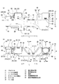
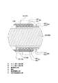
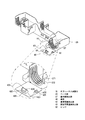
図1はプロテクタ付ハーネス1の概略斜視図を示し、図2はワイヤーハーネス500の収納状態を示し、詳述すると、図2(a)ワイヤーハーネス500の斜視図を示し、図2(b)はワイヤーハーネス500の収納状態の概略図を示す。
FIG. 1 shows a schematic perspective view of the
図3はプロテクタ10の外観を説明する説明図を示し、詳しくは、図3(a)はプロテクタ10の底面図を示し、図3(b)はプロテクタ10の側面図を示す。
FIG. 3 is an explanatory diagram for explaining the external appearance of the
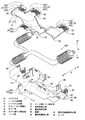
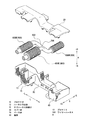
図4および図5は、上下方向からみたプロテクタ10の分解斜視図を示す。図6は図4中のβ部及びγ部の拡大図を示し、詳しくはカバー体20とベース体30とを係止させるカバー側係止部24とベース側固定係止枠34の拡大斜視図を示している。
4 and 5 are exploded perspective views of the
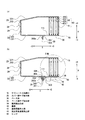
図7は、図3(b)中に示す一点鎖線で切断したA−A断面図であり、カバー体20とベース体30とを係止状態における断面図を示している。同様に、図8は、図3(b)中に示す一点鎖線で切断したB−B断面図であり、閉塞状態と開放状態のハーネス断面図を示している。より具体的には、図8(a)は蓋部40の閉塞状態の、図8(b)は蓋部40の開放状態の断面図を示す。
FIG. 7 is a cross-sectional view taken along the dashed line AA shown in FIG. 3B, and shows a cross-sectional view in a state where the
図9は図8中のδ部の拡大断面図を示し、詳しくはサブ引出口13とコルゲートとの嵌合状態におけるサブ引出口13の拡大断面図を示す。図10は図1中のα部の拡大図を示し、詳しくは蓋部40の閉塞状態における蓋側閉塞係止部42と蓋用被係止部37と係止状態の拡大斜視図を示している。図11は、蓋部40の蓋用固定凸部39の概略斜視図を示す。
FIG. 9 shows an enlarged cross-sectional view of a δ portion in FIG. 8, and specifically shows an enlarged cross-sectional view of the sub-drawer 13 in a fitted state between the sub-drawer 13 and the corrugate. FIG. 10 shows an enlarged view of the part α in FIG. 1, and more specifically shows an enlarged perspective view of the lid side
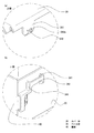
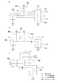
図12は同じプロテクタ10を用いた他のワイヤーハーネス500の収納状態を表す概略斜視図を示し、図13は、異なる使用の車両におけるワイヤーハーネス500の収納状態を示す概略配線図を示す。詳述すると、図13(a)は右ハンドル仕様の自動車のワイヤーハーネス500の概略配線図を示し、図13(b)は左ハンドル仕様の自動車のワイヤーハーネス500の概略配線図を示す。
FIG. 12 is a schematic perspective view showing a storage state of another
図14は、他の形態のプロテクタを平面視した概略配線図を示す。詳述すると、図14(a)は、ハーネス収納部11に沿った対称面に対して面対称となる位置にサブ引出部13が配置されたプロテクタ10の概略配線図を示し、図14(b)は、底面部11の略中央部分おいて底面部101と直交する軸を対称軸としてサブ引出部13を180度回転させた位置に配置したプロテクタ10の概略配線図を示し、図14(b)は、ハーネス収納部11の略中央部分おいて底面部101と直交する軸を対称軸としてサブ引出部13を90度回転させた位置に配置したプロテクタ10の概略配線図を示す。
FIG. 14: shows the schematic wiring diagram which planarly viewed the protector of another form. Specifically, FIG. 14A shows a schematic wiring diagram of the
ここで、図1において、プロテクタ10の長手方向を長手方向L、長手方向と直交する短手方向を短手方向S、長手方向Lおよび短手方向Sの双方に直交する方向を高さ方向Hと定義する。また、図1において、長手方向Lの右側を+L方向、左側を−L方向とし、短手方向Sの手前側を+S方向、奥側を−S方向とする。すなわち、メイン引出部12Bが配置された側を−L方向とし、サブ引出部13Rが配置された側を+L方向とする。また、メイン引出部12Fが配置されている側を−S方向とし、サブ引出部13が配置されている側を+S方向とする。
さらに、プロテクタ10において、カバー材20が配置されている方向を上側とし、ベース材30が配置する方向を下側とする。なお、この軸および方向は、図1乃至図10においても同様とする。
Here, in FIG. 1, the longitudinal direction of the
Further, in the
プロテクタ付ワイヤーハーネス1は、図1に示すように、ワイヤーハーネス500をプロテクタ10に収納したものである。
ワイヤーハーネス500は、図2(a)に示すように、メインハーネス600と、メインハーネス600から分岐したサブハーネス700とで構成しており、ワイヤーハーネス500のうちプロテクタ10に収納されていない箇所は、コルゲートチューブ800で囲繞されている。
As shown in FIG. 1, the
As shown in FIG. 2A, the
メインハーネス600は、導線を絶縁被覆で被覆した被覆電線(図示省略)の束であり、図2(b)に示すように、仕様に関わらず標準装備されている電子機器P同士を接続して主要経路を形成している。
The
サブハーネス700は、メインハーネス600と同様に、被覆電線の束であり、図2に示すように、例えば追加機能として車両に取り付けられたオプション機能を構成するオプション電子機器類Oと接続している。
なお、サブハーネス700は、電気回線を導通する導線を被覆電線で被覆した1本の被覆電線や通信用ケーブルであってもよい。
Similar to the
The sub-harness 700 may be a single covered electric wire or a communication cable in which a conducting wire that conducts an electric line is covered with a covered electric wire.
コルゲートチューブ800は、ワイヤーハーネス500が挿通可能な中空状の樹脂製の保護チューブであり、図9に示すように、全周を凹状とした凹部810と全周を凸状とした凸部820とを交互に配置した蛇腹状に形成されている。
The
なお、コルゲートチューブ800のうち、メインハーネス600を囲繞するものをコルゲートチューブ800M、サブハーネス700を囲繞する物をコルゲートチューブ800Eとする。
Of the
プロテクタ10は、図1に示すように、上面103を形成するカバー体20と、底面部101と側壁部102とを形成するベース体30とで形成された筒状体であり、ワイヤーハーネス500を収納する長手方向Lに沿って延びるハーネス収納部11と、ハーネス収納部11と連結するとともに短手方向Sに延びる2つのメイン引出部12と、ハーネス収納部11から分岐して+S方向に向けて突出する一対のサブ引出部13と、サブ引出部13の下端に設けられた蓋部40とで構成されている。
As shown in FIG. 1, the
ハーネス収納部11は、図1及び図3に示すように、長手方向Lに沿って延びる中空状の筒状体であり、側面からみて中央部分が両端部分と比べて下方に窪んだ形状をしている。
As shown in FIGS. 1 and 3, the
メイン引出部12は、ハーネス収納部11から短手方向Sに突出している箱体であり、その一端側、詳しくはハーネス収納部11と連結している側の反対側端面には、メインハーネス600を引き出すメインハーネス用開口14が形成されている。
The main lead-out
なお、ハーネス収納部11の−L方向側の端部から+S方向側に設けられているメイン引出部12をメイン引出部12Fとし、ハーネス収納部11の中央部分から−S方向側に設けられているメイン引出部12をメイン引出部12Bとする。
In addition, the main drawer | drawing-out
サブ引出部13は、メイン引出部12と同様に、ハーネス収納部11から+S方向に突出している箱体であり、その一端側、詳しくはハーネス収納部11と連結している側の反対側端面には、サブハーネス700を引き出すサブハーネス用開口15が形成されている。また、サブ引出部13の下端には、サブハーネス用開口15を閉塞する蓋部40がヒンジ50を介して一体として連接されている。
The
なお、ハーネス収納部11の+L方向側の端部に設けられたサブ引出部13をサブ引出部13Rとし、ハーネス収納部11の中央部分から+S方向側に設けられたサブ引出部13をサブ引出部13Lとする。
サブ引出部13Rとサブ引出部13Lとは、ハーネス収納部11の窪んだ部位の中心を短手方向Sに沿って底面部101と直交するように形成した対称面SLを中心軸として対称となっている(図3(b)参照)。
In addition, the
The sub lead-out
プロテクタ10の上面側を形成する合成樹脂製のカバー体20は、図4および図5に示すように、ハーネス収納部11の上面部分を形成するカバー側収容部21と、メイン引出部12の上面部分を形成するカバー側メイン引出部22と、サブ引出部13の上面部分を形成するカバー側サブ引出部23とで構成している。
As shown in FIGS. 4 and 5, the synthetic
カバー側収容部21は、ハーネス収納部11の上面を形成するカバー側収容部上面211と、カバー側収容部上面211の端部から下方に僅かに延設するベース側収容部側面212とで構成されている。
The cover
カバー側収容部上面211は、長手方向Lに沿って延びるとともに、側面からみて中央部分が両端と比べて下方に窪んだ形状をしており、この窪んだ位置、メイン引出部12Bとサブ引出部13Lとの間、およびカバー側収容部上面211の両端部の−S方向側には、カバー側係止部24が設けられている。
The cover side accommodating portion
カバー側係止部24は、図6(a)に示すように、カバー側収容部21の下端(カバー側収容部側面212や、後述するカバー側メイン側面222、カバー側サブ側面232)から下方に延設するカバー側支持板241と、カバー側支持板241の先端部分中央から外側に突出するカバー側係止突部242とで構成しており、内側方向に力が作用した場合に内側に撓むことができる程度の弾性を有している。
カバー側支持板241の長さは、カバー側収容部21の側壁の高さよりも少し長く、所定の幅長を有している。
As shown in FIG. 6A, the cover
The length of the cover-
カバー側係止突部242は、カバー側支持板241の下端部分から外側方向に突出する突出部であり、ベース側係止部上面242aがカバー側収容部上面211と平行であるとともに、下方に向けて先細りする略直角三角形状に形成している。なお、カバー側係止突部242の下端側はわずかに丸みを帯びた形状をしている。
The cover-
メイン引出部12の上面部分に対応するカバー側メイン引出部22は、図4および図5に示すように、メイン引出部12の上面であるカバー側メイン上面221と、カバー側メイン側面222と、メインハーネス用開口14側端部から下方に延設されたカバー側メイン引出口側面223で構成されている。また、カバー側メイン側面222の長手方向Lの両端にはカバー側係止部24が設けられ、カバー側メイン引出部22の下面にはカバー側メイン嵌合部25が設けられている。
As shown in FIGS. 4 and 5, the cover-side
カバー側メイン引出口側面223は、カバー側メイン上面221から下方に延設された略五角形状の板体であり、下端部分は、コルゲートチューブ800Mを構成する凹部810の外径と同径の円弧をくり貫いた逆U字状に形成されている。
なお、円弧の頂上点とカバー側メイン上面221の上端との距離は、コルゲートチューブ800Mを構成する凹部810の外径と凸部820の外径との差に略等しい。
The cover-side main
The distance between the top point of the arc and the upper end of the cover-side main
カバー側メイン嵌合部25は、カバー側メイン引出口側面223と同形の板体が、凹部810と凸部820との間隔と等しい間隔で所定の数並んだ構成であり、メインハーネス用開口14を挿通するコルゲートチューブ800Mと嵌合することができる。
The cover-side main
サブ引出部13の上面部分に対応するカバー側サブ引出部23は、カバー側メイン引出部22と同様に、サブ引出部13の上面であるカバー側サブ上面231と、カバー側サブ上面231の長手方向L側端部から下方に延設するカバー側サブ側面232と、サブハーネス用開口15側の端部から下方に延設されておりカバー側サブ引出口側面233とで構成されている。また、カバー側サブ側面232の長手方向Lの両端にはカバー側係止部24が設けられ、カバー側サブ引出部23の下面にはカバー側サブ嵌合部26が設けられている。
Similar to the cover-side
カバー側サブ引出口側面233は、カバー側メイン引出口側面223と同様に、カバー側サブ引出部23から下方に延設された略五角形状の板体であり、コルゲートチューブ800Eを構成する凹部810外径と同径の円弧をくり貫いた逆U字状に形成されている。なお、円弧の頂上点と前記221の上端との距離は、コルゲートチューブ800Eを構成する凹部810の外径と凸部820の外径との差に略等しい。
The cover-side
カバー側サブ嵌合部26は、カバー側サブ引出口側面233と同形の板体が、隣接する凹部810同士の間隔と等しい間隔で所定の数並んだ構成である。詳しくは、凹部810と嵌合するカバー側サブ嵌合凸部261と、凸部820と嵌合するカバー側サブ嵌合凹部262とで構成され、サブハーネス用開口15を挿通するコルゲートチューブ800Eと嵌合できる。
The cover-
プロテクタ10の下方側を形成する合成樹脂製のベース体30は、図4および図5に示すように、上面が開口した箱体であり、カバー体20と同様にワイヤーハーネス500などを収納可能なベース側収容部31と、メインハーネス600を所定の方向に引き出し可能とするベース側メイン引出部32と、サブハーネス700を所定の方向に引き出し可能とするベース側サブ引出部33とで構成しており、カバー体20の装着状態におけるカバー側係止部24と対向する位置にベース側固定係止枠34が設けられている。
As shown in FIGS. 4 and 5, the synthetic
また、ハーネス収納部11Rに対応するベース側メイン引出部32Rとベース側収納部側面312との間、およびハーネス収納部11Lに対応するベース側メイン引出部32Lとベース側収納部側面312との間には、ボルト止め固定部60とクランプ用固定部70とが設けられている。
Moreover, between the base side main drawer | drawing-out part 32R corresponding to the harness accommodating part 11R, and the base side accommodating part side surface 312 and between the base side main drawer | drawing-out part 32L corresponding to the harness accommodating part 11L, and the base side accommodating part side surface 312 Are provided with a
ベース側収容部31は、ハーネス収納部11の下方部分を構成しており、ハーネス収納部11の底面に対応するベース側収納部底面311と、ハーネス収納部11の側面に対応するベース側収納部側面312とが一体となって、上面が開口した箱状体を形成している。
The base
ベース側収納部底面311は、幅がワイヤーハーネス500の外径よりも一回り以上大きく、長手方向Lに沿って延びた板体であり、図3(b)に示すように、側面からみて中央部分から両端に形成された第一ベース側収納部底面311aと、第一ベース側収納部底面311aと比べて下方に窪んだ第二ベース側収納部底面311bと形状をしている。
The base-side storage
ベース側収納部側面312は、ベース側収納部底面311の端部から上方に延設する側壁であり、その高さはワイヤーハーネス500の外径よりも一回り高い。また、カバー体20を取付けた状態においてカバー側係止部24と対向する位置にベース側固定係止枠34が備えられている。
The base-side storage unit side surface 312 is a side wall extending upward from the end of the base-side storage
ベース側固定係止枠34は、図7に示すように、カバー側係止部24を挿入することにより係止してカバー体20とベース体30とを固定する係止枠である。
詳述すると、ベース側固定係止枠34は、図6(b)に示すように、所定の間隔を隔てて外向きに突設する二本のベース体被係止枠341と、ベース体被係止枠341の外側突出方向の端部同士を架設するベース体被係止面342とで一体構成している。
As shown in FIG. 7, the base-side fixing and locking
More specifically, as shown in FIG. 6B, the base-side fixed locking
ベース体被係止枠341の高さ方向Hに対する長さは、カバー側支持板241の長さと略等しく、ベース体被係止枠341同士の間隔はカバー側支持板241の幅長よりも一回り大きい。また、ベース体被係止枠341間を架設するベース体被係止面342の高さ方向Hに対する長さは、ベース側係止部上面242aの上端からカバー側支持板241の上端までの長さよりも一回り短い長さである。
The length of the base body locked
すなわち、カバー体20とベース体30とを嵌合させた状態において、ベース側係止部上面242aはベース体被係止面342の底面と係止するように、ベース体被係止面342の長さが設定されている。
That is, in a state where the
したがって、ベース体30の側面(例えばベース側収納部側面312)と被係止枠341と被係止面342とで形成されるベース側固定係止枠34は、カバー側係止部24を挿入できるとともに、ベース側係止部上面242aと被係止面342の下端とが係止可能な構成となっている。(図7参照)
Therefore, the base side fixed locking
ベース側メイン引出部32は、図4および図5に示すように、メイン引出部12の底面に対応するベース側メイン底面321と、メイン引出部12の側面に対応するベース側メイン側面322と、メインハーネス用開口14側に設けられたベース側メイン開口面323とで構成されており、ベース側メイン引出部32の内部にはベース側メイン嵌合部35が備えられている。
As shown in FIGS. 4 and 5, the base-side
ベース側メイン底面321は、幅がメインハーネス用開口14を挿通するコルゲートチューブ800Mの外径よりも一回り以上大きな板体であり、ベース側メイン底面321の下面には後述する水抜用孔111が設けられている。
The base-side main
なお、ベース側メイン底面321と第一ベース側収納部底面311aは面一となるように形成されている。
The base-side main
ベース側メイン側面322は、ベース側メイン底面321の端部から上方に延設する側壁であり、その高さはコルゲートチューブ800Mの外径よりも一回り高く、またカバー体20を取付けた状態においてカバー側係止部24と対向する位置にベース側固定係止枠34が備えられている。
The base-side
ベース側メイン開口面323は、ベース側メイン底面321の上端やや下方から内側に突出した直線部分と、ベース側メイン底面321のメインハーネス用開口14側端部から上方に延設された下向き円弧で構成されたU字状の板体であり、円弧部分の径はメインハーネス用開口14を挿通するコルゲートチューブ800Mの凹部810と同一の外径である。
The base-side
ベース側メイン嵌合部35は、ベース側メイン底面321と同形の板体が隣接する凹部810同士の間隔と等しい間隔で所定の数並んだ構成である。なお、ベース側メイン開口面323の円弧部分の最下点の高さは、サブハーネス用開口15を挿通するコルゲートチューブ800Mの凹部810の外径と凸部820の外径との差に略等しい。
The base-side main
ベース側サブ引出部33は、サブ引出部13の底面に対応するベース側サブ底面331と、サブ引出部13の側面に対応するベース側サブ側面332と、サブハーネス用開口15側に設けられたベース側サブ開口面333とで構成されており、ベース側サブ引出部33の内部にはベース側サブ嵌合部36が備えられている。
The base side
ベース側サブ底面331は、幅がサブハーネス用開口15を挿通するコルゲートチューブ800Eの外径よりも一回り以上大きな板体であり、下面には、蓋用固定凸部39と水抜用孔111とが設けられている。
なお、ベース側サブ底面331と第一ベース側収納部底面311aは面一となるように形成されている。
The base-
The base-
蓋用固定凸部39は、カバー側係止部24と同一の形状をしている。
詳述すると、図8に示すように、蓋用固定凸部39は、ベース側サブ底面331から下方に向けて突出する蓋用固定板391と、蓋用固定板391の先端部分中央から−S方向に突出する蓋用固定突部392とで構成されており、短手方向Sに力が作用した場合に撓むことができる程度の弾性を有している。
The lid fixing
More specifically, as shown in FIG. 8, the lid fixing
蓋用固定板391の長さは、蓋部40の板厚よりも少し長く、幅長はカバー側支持板241と同じである。なお、蓋用固定板391の長さは、第二ベース側収納部底面311bとベース側サブ底面331および第一ベース側収納部底面311aの高さの差よりも短い構成である。
The length of the
蓋用固定突部392は、開放状態において蓋用固定板391の下端側面から−S方向に突出する突出部であり、正面から見て蓋用固定突部392の上面392aがベース側サブ底面331と平行であるとともに、下方に向けて先細りする略直角三角形状に形成している。なお蓋用固定突部392の下端側は、わずかに丸みを帯びた形状をしている。
なお、水抜用孔111は、ベース側メイン底面321およびベース側サブ底面331を貫通した水抜き用の貫通孔であり、図3(a)および図5に示すように、蓋用固定凸部39よりも外側(+S方向側)に位置する。
The
The
ベース側サブ側面332は、ベース側サブ底面331の端部から上方に延設する側壁であり、その高さはコルゲートチューブ800Eの外径よりも一回り高い。そして、カバー体20を取付けた状態においてカバー側係止部24と対向する位置にベース側固定係止枠34が備えられている。また、+L方向側に設けられたベース側サブ側面332のサブハーネス用開口15側端部の中央部分には、後述する蓋側閉塞係止部42と係止する蓋用被係止部37が備えられている。
The base-side
蓋用被係止部37は、カバー側係止部24と同様に、+L方向側のベース側サブ側面332から外側(+L方向側)向けて突設する二本の蓋用被係止枠371と、蓋用被係止枠371のサブハーネス用開口15側端部を架設する蓋用被係止面372とで一体構成している。
Similarly to the cover
蓋用被係止枠371は、短手方向Sに沿って所定の間隔を隔てて配設されており、その短手方向Sに対する長さはカバー側支持板241の高さ方向Hの長さと略等しく、幅方向Wの長さはカバー側支持板241の幅方向Wの長さと略等しい。また、蓋用被係止枠371の間を架設する蓋用被係止面372の短手方向Sに対する長さは、ベース側係止部上面242aの上端からカバー側支持板241の上端までの長さよりも一回り短い長さであり、蓋用被係止枠371の間隔、すなわち蓋用被係止面372の幅はカバー側支持板241の幅よりも一回り大きい。
The
なお、図4に示すように、上方に位置する蓋用被係止枠371とサブハーネス用開口15側に位置するベース体被係止枠341とは端部同士が連結されており、ベース側固定係止枠34および蓋用被係止部37の剛性を高めている。
As shown in FIG. 4, the lid locked
ベース側サブ開口面333は、ベース側サブ側面332の上端やや下方から内側に突出した直線部分と、ベース側サブ底面331のサブハーネス用開口15側の端部から上方に延設された下向き円弧で構成されたU字状の板体であり、円弧部分の径はサブハーネス用開口15を挿通するコルゲートチューブ800Eの凹部810と同一の外径である。
The base-side
ベース側サブ嵌合部36は、ベース側サブ開口面333と同形の板体が凹部810と凸部820との間隔と等しい間隔で所定の数並んだ構成である。詳しくは、凹部810と嵌合するカバー側サブ嵌合凸部261と、凸部820と嵌合するカバー側サブ嵌合凹部262とで構成されており、図9に示すように、サブハーネス用開口15から引き出されるサブハーネス700を保護するコルゲート800Eとカバー側サブ嵌合部26およびベース側サブ嵌合部36とが嵌合することができる。
The base side
また、ベース側サブ開口面333の下端部、すなわちベース側サブ底面331のサブハーネス用開口15側端部には、ヒンジ50を介して蓋部40が一体として連結されている。
蓋部40は、サブ引出部13のサブハーネス用開口15を閉塞可能な大きさの閉塞版41と、閉塞板41の+L側端部に設けられた蓋側係止部42と、閉塞板41の略中央部分に設けられた固定用貫通被係止部43とで構成されている。
Further, the
The
閉塞板41は、カバー側サブ上面231とベース側サブ底面331とベース側サブ側面332とで形成した四角形と同形の一枚板であり、板厚が蓋用固定突部392の上面392aとベース側サブ底面331との間の長さと略等しい構成である。また、閉塞板41の閉塞状態における下端側端部は、ヒンジ50と一体に連結されており、ヒンジ50を枢動軸として枢動し、蓋部40がサブハーネス用開口15を閉塞しない開放状態と蓋部40がサブハーネス用開口15を閉塞した閉塞状態とを移行することができる。
The closing
蓋側閉塞係止部42は、図10に示すように、蓋用被係止部37と係止することにより蓋部40をベース側サブ引出部33に固定する固定具であり、カバー側係止部24と同形である。
この蓋側閉塞係止部42は、閉塞状態において閉塞板41の+L側端部の上方部分から−S方向に延設する蓋側支持板421と、蓋側支持板421の先端部分中央から外側(+L側)に突出する蓋側係止突部422とで構成しており、長手方向Lに力が作用した場合に撓むことができる程度の弾性を有している。
As shown in FIG. 10, the lid-side
In the closed state, the lid-side
蓋側閉塞支持板421の長さは、カバー側支持板241の長さと等しく、所定の幅長を有している。
蓋側閉塞係止突部422は、カバー側係止突部242と同じ形状している。詳しくは、蓋側閉塞係止突部422は、蓋側閉塞支持板421から外側方向に突出する突出部であり、正面からみて蓋側閉塞係止突部422の側面422aが閉塞板41と平行であるとともに、−S方向に向けて先細りする略直角三角形状に形成している。なお蓋側閉塞係止突部422の先端は、わずかに丸みを帯びた形状をしている。
The length of the lid-side
The lid
固定用貫通被係止部43は、図8(a)および図11に示すように、開放状態において蓋用固定凸部39が貫通する位置に設けられた被係止部であり、閉塞板41の略中央部分を貫通する貫通孔と、蓋部40がサブハーネス用開口15を閉塞した閉塞状態において内部側に突出する係止用の枠体とで構成されている。
As shown in FIG. 8A and FIG. 11, the fixing penetration locked
詳述すると、固定用貫通被係止部43は、閉塞状態において所定の間隔を隔てて内向きに突設する四角形状のベース体被係止枠431と、ベース体被係止枠431上方側の基端部分同士を架設するベース体被係止面432と、ベース体被係止枠431の下方側を架橋する係止枠固定面433と、ベース体被係止面432とベース体被係止枠431の間において閉塞板41を貫通する係止凸部貫通孔434と、ベース体被係止面432を対称面として面対称となる位置において閉塞板41を貫通した係止補助用貫通孔435とが一体構成している。
More specifically, the fixing penetration locked
ベース体被係止枠431は、図11に示すように、閉塞状態において内側に向けて延びる四角形状の板体による枠であり、閉塞板41に対して直交する方向への長さは、蓋用固定板391の長さと略等しく、ベース体被係止枠431同士の間隔は蓋用固定凸部39の幅長よりも一回り大きい。
As shown in FIG. 11, the base body locked
ベース体被係止枠431の基端側端部同士を架設するベース体被係止面432は、高さが蓋用固定突部392の上面392aから蓋用固定板391の先端までの長さよりも一回り短い長さである。すなわち、蓋部40を枢動させて蓋用固定凸部39と固定用貫通被係止部43とを嵌合させた状態において、蓋用固定突部392の上面392aはベース体被係止面432の底面と係止するように、ベース体被係止面432の長さが設定されている(図8(b)参照)。
The base body locked
係止枠固定面433は、閉塞状態において、ベース体被係止枠431の下方側端部を架橋する板状体である。
係止凸部貫通孔434は、閉塞板41を貫通した貫通孔であり、その縦幅(閉塞状態における高さ方向Hの幅)は蓋用固定板391の縦幅よりも一回り長く、横幅(閉塞状態における短手方向Sの幅)は蓋用固定突部392が挿通可能な程度の長さである。すなわち、係止凸部貫通孔434は蓋用固定凸部39を挿通可能な貫通孔である。なお、係止凸部貫通孔434の位置は、閉塞状態においてベース側サブ開口面333、およびカバー側サブ引出口側面233と重複しない位置に配置されている。これにより、閉塞状態において係止凸部貫通孔434からプロテクタ10の中を確認することができる。
The locking
The locking projection through-
係止補助用貫通孔435は、閉塞板41を貫通した貫通孔であり、ベース体被係止枠431を対称軸として係止凸部貫通孔434と対向する位置に設けられている。係止補助用貫通孔435の縦幅は係止凸部貫通孔434よりの縦幅よりも長く、又係止補助用貫通孔435の横幅(厚さ)は係止凸部貫通孔434の横幅よりも短く形成されている。
The locking auxiliary through
係止補助用貫通孔435を係止凸部貫通孔434の上方側に配置することにより、係止凸部貫通孔434を蓋用固定凸部39が挿通した際に係止凸部貫通孔434の上方側の枠部分が係止補助用貫通孔435側に撓ますことができるため、蓋用固定凸部39の挿通を補助することができる。
ヒンジ50は、ベース側サブ底面331に対して蓋部40を枢動させる枢動軸となる位置に配設しており、図8示すように、蓋部40が枢動して開閉するように支持している。
By disposing the latching auxiliary through
The
このような構成を有することで、ヒンジ50を枢動軸として蓋部40を枢動させることで、図8(a)に示すように、蓋部40がサブハーネス用開口15を閉塞する位置において、蓋側閉塞係止部42を蓋用被係止部37に挿入して係止させることで、蓋部40をサブ引出部13に固定することができる。
By having such a configuration, the
また、図8(b)に示すように、蓋部40がベース側サブ底面331と対向する位置までヒンジ50を枢動軸として蓋部40を枢動させることにより、蓋用固定凸部39が係止凸部貫通孔434に挿通されるとともに、蓋用固定突部392の上面392aがベース体被係止面432と係止することとなり、蓋部40をベース側サブ底面331とに固定できる。
Further, as shown in FIG. 8B, the lid fixing
ベース側メイン引出部32Lとベース側収納部側面312との間に設けられたボルト止め固定部60は、図示しない車両本体とプロテクタ10とをボルトで固定するための固定具であり、ベース側収納部側面312とベース側サブ側面332とに跨って形成された固定面61と、固定面61の中央部分に設けられたボルトを挿通させるためのボルト用貫通孔62とで構成されている。
A
ボルト用貫通孔62の高さは第二ベース側収納部底面311bと略同一の高さに形成されている。
なお、ボルト止め固定部60の+S方向側側面は、ベース体被係止枠341の一方と連結することによりベース側固定係止枠34の剛性を高めている。
The height of the bolt through
The + S direction side surface of the
クランプ用固定部70は、ヒンジ50と同様に、図示しない車両本体と固定するためのクランプ止めであり、中央部分に車両本体に設けたクランプ(図示省略)を挿通させるための貫通孔を有している。また、クランプ用固定部70の+S方向側側面は、ベース体被係止枠341の一方と連結することによりベース側固定係止枠34の剛性を高めている。
なお、クランプ用固定部70の底面は第一ベース側収納部底面311aの底面と略面一となっている。
The
The bottom surface of the
ボルト止め固定部60とクランプ用固定部70を備えることにより、底面部101と車両本体とが対向するようにプロテクタ10を車両本体に配置し、ボルト止め固定部60にボルトを挿通して固定するとともに、クランプ用固定部70にクランプを挿通させることで、プロテクタ10を車両本体に固定することができる。
By providing the
このように、底面部101と、底面部101の幅方向両端から延設する側壁部102と、側壁部102の上面側に形成される開口を覆う上面103とで構成され、ワイヤーハーネス500を収納するプロテクタ10であって、ワイヤーハーネス500を収納ハーネス収納部11と、ハーネス収納部11と連結するとともに、ハーネス収納部11からサブハーネス700が引き出すサブハーネス用開口15が備えられたサブ引出部13とで構成され、サブハーネス用開口15を開閉する蓋部40と、蓋部40よるサブハーネス用開口15の閉塞状態を保持する蓋用被係止部37および蓋側閉塞係止部42と、蓋部40よるサブハーネス用開口15の開放状態を保持する蓋用固定凸部39および固定用貫通被係止部43とが備えられたことにより、プロテクタ10は例えばワイヤーハーネス500の配索が異なるなど仕様が異なっていても共用できるとともに、使用しないサブハーネス用開口15を閉塞することで内部への異物の侵入を防止できる。
As described above, the
詳述すると、例えば図2(b)に示すように、オプションで追加する電子機器類であるオプション電子機器類Oに対応する位置に設けられたサブ引出部13Rに備わるサブハーネス用開口15からサブハーネス700を引き出しオプション機器と接続することができる。
More specifically, for example, as shown in FIG. 2B, the
一方で、仕様によりオプション電子機器類Oが配置されていないサブ引出部13Lでは、蓋部40を蓋用被係止部37と蓋側閉塞係止部42とで保持することにより、サブハーネス用開口15を蓋部40で閉塞することができ、サブ引出部13Lのサブハーネス用開口15からプロテクタ10の内部に小石や水などの異物が侵入することを防止できる。このように、使用しないサブ引出部13Lのサブハーネス用開口15を蓋部40で閉塞することができるため、内部への異物の侵入を防止できるとともに、仕様が異なる車両に対してプロテクタ10を共用できる。
On the other hand, in the
また、蓋部40の一端側を枢動軸として蓋部40を枢支するヒンジ50を備えることにより、ヒンジ50を中心として蓋部40を枢動操作してサブハーネス用開口15を開放状態から閉塞状態へ相互に移行できる。
すなわち、蓋部40を枢動操作するだけで、サブハーネス用開口15の開放動作および閉塞動作を容易に行うことができ、作業性を向上させることができる。
Further, by providing a
That is, the opening operation and the closing operation of the
また、ヒンジ50が、ベース側サブ底面331に設けられとともに、蓋部40を固定する蓋用固定凸部39がベース側サブ底面331に設けられたことにより、蓋部40がヒンジ50を中心として枢動することができるとともに、蓋部40を底面部101に固定することができる。これにより、仮に蓋用固定凸部39と固定用貫通被係止部43の係止が解除された場合であっても、蓋部40がプロテクタ10の上面側に配置された他の部材と干渉することを防止できる。したがって、他の部材を損傷することを防止できる。
In addition, since the
また、プロテクタ10を図示しない車両本体などに組付けた場合において、万が一蓋部40を固定する蓋用固定凸部39と固定用貫通被係止部43の係止が解除された場合であっても、蓋部40は枢動して車両本体と接触するため、サブハーネス用開口15側に枢動すること防止できる。これにより、蓋部40は車両本体と干渉するため蓋部40がサブハーネス用開口15から引き出されたワイヤーハーネス500と干渉することを防止でき、ワイヤーハーネス500が損傷されることを防止できる。
In addition, when the
さらに、開放状態における蓋部40および蓋用固定凸部39と固定用貫通被係止部43が車両本体側に隠れることとなるため、プロテクタ10の周囲に電子機器類などを容易に配置できるとともに、車両本体に組付けたプロテクタ10の見栄えに優れている。
Further, since the
また、ベース側サブ底面331に、閉塞状態において外側に突出する蓋用固定凸部39を設け、蓋部40に開放状態において蓋用固定凸部39が挿通して係合する固定用貫通被係止部43とで構成されたことにより、蓋部40をベース側サブ引出部33に確実に固定できる。
In addition, a fixing
詳述すると、ベース側サブ底面331に設けた蓋用固定凸部39が固定用貫通被係止部43を貫通することで蓋部40をベース側サブ底面331に固定するため、プロテクタ10を車両本体などに組付けた場合に、蓋用固定凸部39が周囲に配置された他の部材と干渉を防止し、蓋用固定凸部39と固定用貫通被係止部43とによる蓋部40の固定が容易に外れることを防止できる。すなわち、蓋部40をサブ引出部13に確実に固定できる。
また、ベース側サブ底面331を鉛直下側とした場合、蓋部40の自重で開放状態から閉塞状態に戻ることがないため、ワイヤーハーネス500と干渉して損傷することを防止できる。
More specifically, the lid fixing
Further, when the base-
さらにまた、蓋用固定凸部39をベース側サブ底面331に設けるため、例えばプロテクタ10を車両本体に固定するボルト止め固定部60やクランプ用固定部70をプロテクタ10の側壁部102側に設けることや、側壁部102の周辺に他の部材を配置することができる。
さらには、閉塞状態において、固定用貫通被係止部43からプロテクタ10の内部を確認することができる。
Furthermore, in order to provide the fixing
Further, in the closed state, the inside of the
また、サブ引出部13の底面部分であるベース側サブ底面331が、ハーネス収納部11の底面部分であるベース側収納部底面311(第二ベース側収納部底面311b)よりも蓋用固定凸部39の高さ以上上面側に配置されたことにより、プロテクタ10を車両本体などに配置する場合において、蓋用固定凸部39が車両本体と干渉することなくプロテクタ10を配置することができる。
Further, the base-
詳述すると、例えば、蓋用固定凸部39が備えられたベース側サブ引出部33の底面ベース側サブ底面331がベース側収容部31の底面であるベース側収納部底面311(第二ベース側収納部底面311b)と同じ高さであるプロテクタ10を車両本体などに組付ける場合、蓋用固定凸部39が下方に突出しているため車両本体と干渉することとなるため、プロテクタ10を配置するためには、蓋用固定凸部39を収容する収容部を車両本体側に設ける必要がある。
More specifically, for example, a base-side storage unit bottom surface 311 (second base side) in which the bottom-side base-
しかしながら、ベース側サブ底面331がベース側収納部底面311(第二ベース側収納部底面311b)よりも蓋用固定凸部39の高さ分だけ上面側に配置される構成とすることにより、蓋用固定凸部39が車両本体と干渉することを防止でき、プロテクタ10を車両本体などに安定して組付けることができる。
However, the base-
また、蓋部40とベース側サブ引出部33とがヒンジ50を介して一体で形成したことにより、蓋部40をベース側サブ引出部33に取り付ける作業を行うことなく、蓋部40をベース側サブ引出部33に固定できるため作業性を向上できる。また、プロテクタ10を構成する蓋部40を紛失することがなく、さらには部品点数を削減することができる
Further, since the
さらにまた、蓋用被係止部37がベース側サブ側面332に、蓋側閉塞係止部42が蓋部40に設けられたことにより、蓋用被係止部37と蓋側閉塞係止部42とを係止することで閉塞状態をより確実に維持できるとともに、プロテクタ10を組付ける車両本体およびプロテクタ10の上面側に配置される他の部材との干渉を防止することができる。
Furthermore, the lid locked
詳述すると、蓋用被係止部37がベース側サブ底面331に設けられた場合、プロテクタ10を車両本体などに組付ける際に、蓋用被係止部37が車両本体と干渉するため、プロテクタ10を安定した状態で車両本体に組付けることができない。同様に、蓋用被係止部37がカバー側サブ上面231に設けられた場合には、上面側に他の部材を配置する際に蓋用被係止部37と干渉するおそれがある。
More specifically, when the
これに対して、ベース側サブ側面332に蓋用被係止部37を設け、蓋部40に蓋側閉塞係止部42を設けることにより、プロテクタ10の車両本体などへの組付けや、蓋用被係止部37および蓋側閉塞係止部42他の部材との干渉を防止できるとともに、蓋用被係止部37および蓋側閉塞係止部42材が他の部材などと干渉しないため、閉塞状態をより確実に保持できる。
On the other hand, the lid
さらにまた、一対のサブ引出部13が、ハーネス収納部11の軸方向と交差する交差方向に沿って配置されるとともに、ハーネス収納部11の底面部101と直交する対称面SLに対して面対称となる位置に配置されたことにより、例えば図12に示すように、右ハンドル仕様と左ハンドル仕様のように、仕様によってワイヤーハーネス500の配索が対称となる車両に対しても対応できる、より汎用性の高いプロテクタ10とすることができる。
Furthermore, the pair of sub lead-out
詳述すると、プロテクタ10は一対のサブ引出部13のうちのサブ引出部13Rとサブ引出部13Lとを直交軸方向に対して軸対称に配置されている。ここで、図13(a)および図4に示すように、右ハンドル仕様の自動車にプロテクタ10を搭載する場合、右ハンドル仕様に対応して搭載されたオプション電子機器類Oに対応した位置にサブ引出部13Rが配置されるため、サブ引出部13Rのサブハーネス用開口15から引き出されたサブハーネス700をオプション電子機器類Oと接続できるとともに、サブ引出部13Lのサブハーネス用開口15を蓋部40で閉塞することができる。
More specifically, in the
これに対して、図13(b)に示すように、右ハンドル仕様の自動車と比較して、オプション電子機器類Oが対称面SLを中心として面対称となる位置に配置された左ハンドル仕様の車両に対しては、図12に示すように、対称面SLと直交軸方向とを合わせることでサブ引出部13Lのサブハーネス用開口15から引き出されたワイヤーハーネス500をオプション電子機器類Oと接続でき、サブ引出部13Rのサブハーネス用開口15を蓋部40で閉塞することができる。
On the other hand, as shown in FIG. 13 (b), as compared with a right-hand drive vehicle, the option electronic device O has a left-hand drive specification in which the optional electronic equipment O is disposed at a position that is plane-symmetric about the symmetry plane SL. For the vehicle, as shown in FIG. 12, the
このように、ある仕様の車両に搭載されている電子機器類と、別の仕様の車両に搭載されている同一の電子機器類とが、所定の軸に対して軸対称あるいは点対称となる位置に配置されている場合であっても、両方の仕様においてワイヤーハーネス500をプロテクタ10に収納できるとともに他方からの異物の侵入を防止できる、より汎用性を有するプロテクタ10とすることができる。
したがって、仕様に応じて別途プロテクタ10を製造する必要がなく、管理コストや製造コストを削減することができる。
As described above, the position where the electronic devices mounted on a vehicle with a certain specification and the same electronic devices mounted on a vehicle with another specification are axially symmetric or point-symmetric with respect to a predetermined axis. Even if it is a case where it is arrange | positioned, it can be set as the
Therefore, it is not necessary to manufacture the
また、プロテクタ10を、カバー体20とベース体30とで構成したことにより、ワイヤーハーネス500を容易にハーネス収納部11、メイン引出部12およびサブ引出部13に容易に収納することができる。
Further, since the
詳述すると、プロテクタ10のカバー体20をベース体30から取り外すことで、ワイヤーハーネス500をプロテクタ10に上面側から容易に収納することができるとともに、ワイヤーハーネス500の枝線であるサブハーネス700をサブ引出部13から容易に引き出すことができる。
More specifically, by removing the
また、サブ引出部13(カバー側サブ引出部23およびベース側サブ引出部33)に、サブハーネス用開口15から引き出されたサブハーネス700を保護するコルゲートチューブ800Eと嵌合するカバー側サブ嵌合部26およびベース側サブ嵌合部36を設けたことにより、サブハーネス700の外周を保護するコルゲートチューブ800Eが、カバー側サブ嵌合部26およびベース側サブ嵌合部36と嵌合するため、サブハーネス700が引き出されたサブハーネス用開口15からの異物の侵入をより確実に防止でき、ワイヤーハーネス500の損傷を防止できる。加えて、サブ引出部13から引き出されたワイヤーハーネス500の位置ずれを防止することができる。
Moreover, the cover side sub fitting which fits with the
さらに、プロテクタ10はカバー体20とベース体30とに分かれているため、ワイヤーハーネス500をベース体30に収納してコルゲートチューブ800Eをベース側サブ嵌合部36に嵌合させた後に、カバー体20を上方から取り付けてカバー側サブ嵌合部26とコルゲートチューブ800Eとを嵌合させることができるため、プロテクタ10とコルゲートチューブ800Eとをより確実に嵌合させることができる。
Furthermore, since the
この発明の構成と、上述の実施形態との対応において、
開口部は、サブハーネス用開口15に対応し、
ハーネス引出部は、サブ引出部13に対応し、
開放保持部は、蓋用固定凸部39および固定用貫通被係止部43に対応し、
閉塞保持部は、蓋用被係止部37および蓋側閉塞係止部42に対応し、
枢支手段は、ヒンジ50に対応し、
凸部は、蓋用固定凸部39に対応し、
挿通孔は、固定用貫通被係止部43に対応し、
保護部材800は、コルゲート800に対応し、
嵌合溝部は、カバー側サブ嵌合部26およびベース側サブ嵌合部36に対応するが、
この発明は、上述の実施形態の構成のみに限定されるものではなく、多くの実施の形態を得ることができる。
In correspondence between the configuration of the present invention and the above-described embodiment,
The opening corresponds to the
The harness lead portion corresponds to the
The opening holding portion corresponds to the lid fixing
The closure holding portion corresponds to the lid locked
The pivot means corresponds to the
The convex portion corresponds to the fixed
The insertion hole corresponds to the fixing through-
The
The fitting groove portion corresponds to the cover side
The present invention is not limited only to the configuration of the above-described embodiment, and many embodiments can be obtained.
例えば、本実施例において、ハーネス引出部13は2個としているが、必ずしも2個である必要はなく、様々な仕様の車両に配置する予定の電子機器類の数に合わせて適宜調整できる。
For example, in the present embodiment, the number of harness lead-out
また、複数配置されたハーネス引出部13はすべてが左右対称である必要もなく、ハーネス収納部11における所定の点を対称点として点対称となる位置に設けてもよい。
Further, the plurality of harness lead-out
また、本実施例において、ハーネス引出部13は短手方向Sに沿って形成された対称面SLを対称面として面対称となる位置に配置されているが、必ずしも短手方向Sに沿った対称面SLを対称面とする面対称とする必要はなく、例えば図14に示すように、ハーネス引出部13を異なる位置に配置することができる。
Further, in the present embodiment, the harness lead-out
具体的には、図14(a)に示すように、長手方向Lに沿って形成された対称面LSに対して面対称となるようにハーネス引出部13を配置することができる。換言すると、ハーネス収容部11の端部から±S方向にハーネス引出部13が突出するように配置できる。
Specifically, as illustrated in FIG. 14A, the harness lead-out
また、図14(b)や図14(c)に示すように、ハーネス収納部11の窪んだ部位の中心に下した回転軸Cを中心に回転させた位置にハーネス引出部13を配置することができる。
このように、ハーネス引出部13が所定の面に対して面対称となる平面視T字状となるように配置されたり、平面視S字状となるように配置されたりすることができるため、電子機器類が異なる位置に配置される仕様であっても共用できる。
Further, as shown in FIG. 14B and FIG. 14C, the harness lead-out
In this way, the harness lead-out
1 プロテクタ付きワイヤーハーネス
10 プロテクタ
11 ハーネス収納部
13 ハーネス引出部
15 サブハーネス用開口
20 カバー体
26 カバー側サブ嵌合部
30 ベース体
35 ベース側メイン嵌合部
37 蓋用被係止部
39 蓋用固定凸部
40 蓋部
42 蓋側閉塞係止部
43 固定用貫通被係止部
50 ヒンジ
101 底面部
102 側壁部
103 上面部
500 ワイヤーハーネス
800 コルゲート
DESCRIPTION OF
Claims (11)
前記ワイヤーハーネスが収納されるハーネス収納部と、
該ハーネス収納部と連結するとともに、前記ハーネス収納部に収容された前記ワイヤーハーネスが引き出される開口部が備えられたハーネス引出部とで構成され、
前記開口部を開閉する蓋部と、
該開口部の蓋部による閉塞状態を保持する閉塞保持部と、
前記蓋部による前記開口部の開放状態を保持する開放保持部とが備えられた
プロテクタ。 A protector for housing a wire harness, comprising a bottom surface portion, a side wall portion extending from both ends of the bottom surface portion in the width direction, and an upper surface portion covering an opening formed on the upper surface side of the side wall portion,
A harness storage section in which the wire harness is stored;
The harness storage unit is connected to the harness storage unit, and is configured with a harness lead-out unit provided with an opening through which the wire harness stored in the harness storage unit is pulled out.
A lid for opening and closing the opening;
An occlusion holding portion for holding an occlusion state by the lid portion of the opening;
The protector provided with the open holding | maintenance part which hold | maintains the open state of the said opening part by the said cover part.
請求項1に記載のプロテクタ。 The protector of Claim 1 provided with the pivot means which pivotally supports the said cover part by making the one end side of the said cover part into a pivot axis.
前記開放保持部は、
前記ハーネス引出部の底面側に設けられ、前記蓋部を固定する固定部で構成された
請求項2に記載のプロテクタ。 The pivot support means is provided on the bottom surface portion of the harness lead portion,
The open holding part is
The protector according to claim 2, wherein the protector is configured by a fixing portion that is provided on a bottom surface side of the harness lead portion and fixes the lid portion.
前記底面または前記蓋部の一方に、前記閉塞状態において外向きに凸状の凸部と、
他方に、前記開放状態において前記凸部が挿通して係合する挿通孔とで構成された
請求項3に記載のプロテクタ。 The fixing part is
On one of the bottom surface or the lid portion, a convex portion protruding outward in the closed state,
On the other hand, the protector according to claim 3, wherein the protector is configured with an insertion hole through which the convex portion is inserted and engaged in the open state.
前記蓋部に前記凸部が備えられた場合に、前記ハーネス引出部における底面部分が、少なくとも前記ハーネス収納部における底面部分よりも前記蓋部の板厚以上上面側に配置された
請求項4に記載のプロテクタ。 When the convex portion is provided on the bottom surface, at least the bottom surface portion in the harness lead-out portion is arranged on the upper surface side more than the height of the convex portion than the bottom surface portion in the harness storage portion,
5. When the convex part is provided in the lid part, the bottom surface part in the harness lead-out part is disposed on the upper surface side at least more than the thickness of the lid part than the bottom surface part in the harness storage part. The protector described.
請求項1乃至請求項5のうちのいずれかに記載のプロテクタ。 The protector according to any one of claims 1 to 5, wherein the lid portion and the harness lead-out portion are integrally formed.
請求項1乃至請求項6のうちのいずれかに記載のプロテクタ。 The protector in any one of Claims 1 thru | or 6 with which the said obstruction | occlusion holding | maintenance part was provided in the said side wall part.
前記ハーネス収納部の軸方向と交差する交差方向に向いて配置され、
前記ハーネス引出部のうちの少なくとも一対が、
前記ハーネス収容部の底面部または上面部と直交する直交面に対して面対称となる位置に、
あるいは、
前記軸方向の点を対称点とし、前記ハーネス収容部の底面部または上面部と平行な面に沿って回転対称となる位置に配置されている
請求項1乃至請求項7のうちのいずれかに記載のプロテクタ。 A plurality of the harness lead portions are provided,
Arranged in the crossing direction intersecting the axial direction of the harness storage part,
At least a pair of the harness lead portions is
In a position that is plane-symmetric with respect to an orthogonal plane that is orthogonal to the bottom surface or top surface of the harness housing portion,
Or
8. The device according to claim 1, wherein the axial point is a symmetric point, and is arranged at a position that is rotationally symmetric along a plane parallel to the bottom surface or the top surface of the harness housing portion. The protector described.
前記底面部および前記側壁部で構成されるベース体と、
前記上面部を構成するカバー体とで構成された
請求項1乃至請求項8のうちのいずれかに記載のプロテクタ。 The protector body is
A base body composed of the bottom surface portion and the side wall portion;
The protector in any one of Claims 1 thru | or 8 comprised with the cover body which comprises the said upper surface part.
前記開口部から引き出された前記ワイヤーハーネスを囲繞して保護する保護部材と嵌合する嵌合溝部が設けられた
請求項1乃至請求項9のうちのいずれかに記載のプロテクタ。 In the front harness drawer,
The protector in any one of Claim 1 thru | or 9 with which the fitting groove part fitted with the protection member which surrounds and protects the said wire harness pulled out from the said opening part was provided.
前記ワイヤーハーネスが収納されるとともに、
前記ワイヤーハーネスが引き出されない前記開口部が前記蓋部で閉塞された
プロテクタ付きワイヤーハーネス。 The protector according to any one of claims 1 to 10,
The wire harness is stored,
A wire harness with a protector in which the opening from which the wire harness is not pulled out is closed by the lid.
Priority Applications (1)
| Application Number | Priority Date | Filing Date | Title |
|---|---|---|---|
| JP2016002553A JP6623068B2 (en) | 2016-01-08 | 2016-01-08 | Protector and wire harness with protector |
Applications Claiming Priority (1)
| Application Number | Priority Date | Filing Date | Title |
|---|---|---|---|
| JP2016002553A JP6623068B2 (en) | 2016-01-08 | 2016-01-08 | Protector and wire harness with protector |
Publications (2)
| Publication Number | Publication Date |
|---|---|
| JP2017123754A true JP2017123754A (en) | 2017-07-13 |
| JP6623068B2 JP6623068B2 (en) | 2019-12-18 |
Family
ID=59306016
Family Applications (1)
| Application Number | Title | Priority Date | Filing Date |
|---|---|---|---|
| JP2016002553A Active JP6623068B2 (en) | 2016-01-08 | 2016-01-08 | Protector and wire harness with protector |
Country Status (1)
| Country | Link |
|---|---|
| JP (1) | JP6623068B2 (en) |
Cited By (2)
| Publication number | Priority date | Publication date | Assignee | Title |
|---|---|---|---|---|
| JP2020162242A (en) * | 2019-03-26 | 2020-10-01 | 矢崎総業株式会社 | Protector |
| US10906481B2 (en) | 2018-03-12 | 2021-02-02 | Toyota Jidosha Kabushiki Kaisha | Protector |
Citations (3)
| Publication number | Priority date | Publication date | Assignee | Title |
|---|---|---|---|---|
| JPH08251754A (en) * | 1995-03-03 | 1996-09-27 | Sumitomo Wiring Syst Ltd | Protector for wire harness forming |
| JP2009050107A (en) * | 2007-08-21 | 2009-03-05 | Yazaki Corp | Wire harness lead-out structure of the protector |
| JP2014110722A (en) * | 2012-12-04 | 2014-06-12 | Sumitomo Wiring Syst Ltd | Protector |
-
2016
- 2016-01-08 JP JP2016002553A patent/JP6623068B2/en active Active
Patent Citations (3)
| Publication number | Priority date | Publication date | Assignee | Title |
|---|---|---|---|---|
| JPH08251754A (en) * | 1995-03-03 | 1996-09-27 | Sumitomo Wiring Syst Ltd | Protector for wire harness forming |
| JP2009050107A (en) * | 2007-08-21 | 2009-03-05 | Yazaki Corp | Wire harness lead-out structure of the protector |
| JP2014110722A (en) * | 2012-12-04 | 2014-06-12 | Sumitomo Wiring Syst Ltd | Protector |
Cited By (3)
| Publication number | Priority date | Publication date | Assignee | Title |
|---|---|---|---|---|
| US10906481B2 (en) | 2018-03-12 | 2021-02-02 | Toyota Jidosha Kabushiki Kaisha | Protector |
| JP2020162242A (en) * | 2019-03-26 | 2020-10-01 | 矢崎総業株式会社 | Protector |
| JP7235550B2 (en) | 2019-03-26 | 2023-03-08 | 矢崎総業株式会社 | protector |
Also Published As
| Publication number | Publication date |
|---|---|
| JP6623068B2 (en) | 2019-12-18 |
Similar Documents
| Publication | Publication Date | Title |
|---|---|---|
| JP2016119740A (en) | Protector and wiring harness | |
| CN108418150B (en) | Protectors and wiring harnesses | |
| JP3293556B2 (en) | Protector | |
| JP5013781B2 (en) | Electrical junction box | |
| CN108475903A (en) | Method for the protector of harness and for manufacturing harness | |
| JP2002225648A (en) | Wire harness protector and wire harness mounting method and structure using the same | |
| JP6623068B2 (en) | Protector and wire harness with protector | |
| JP2018093671A (en) | Electrical junction box and wire harness | |
| JP7339225B2 (en) | Resin structure and wire harness | |
| JP6475689B2 (en) | Electrical junction box arrangement structure, electrical junction box, wire harness, and vehicle | |
| JP6339607B2 (en) | Protector and wire harness with protector | |
| JP7314766B2 (en) | protector and routing unit | |
| JP7100445B2 (en) | Housing, electrical junction box, and wire harness | |
| JP2018186624A (en) | Electric connection box and wire harness | |
| JP2018001905A (en) | Interior member | |
| JP2021005948A (en) | Protector for wire harnesses and wire harness with protector | |
| JP7235550B2 (en) | protector | |
| JP2015074307A (en) | Electric wire guide device | |
| JP2023132009A (en) | Protector with clamp, wire harness with protector and clamp | |
| JP5644126B2 (en) | Electrical component with hinged lid | |
| JP7513664B2 (en) | Electrical connection box and manufacturing method | |
| JP2018153031A (en) | Protector and wire harness | |
| JP6831822B2 (en) | Protector | |
| JP3414309B2 (en) | Electrical junction box | |
| JP2005065399A (en) | Method of manufacturing protector and wire harness |
Legal Events
| Date | Code | Title | Description |
|---|---|---|---|
| RD01 | Notification of change of attorney |
Free format text: JAPANESE INTERMEDIATE CODE: A7426 Effective date: 20160115 |
|
| A521 | Request for written amendment filed |
Free format text: JAPANESE INTERMEDIATE CODE: A821 Effective date: 20160115 |
|
| A711 | Notification of change in applicant |
Free format text: JAPANESE INTERMEDIATE CODE: A711 Effective date: 20160628 |
|
| A521 | Request for written amendment filed |
Free format text: JAPANESE INTERMEDIATE CODE: A821 Effective date: 20160628 |
|
| A711 | Notification of change in applicant |
Free format text: JAPANESE INTERMEDIATE CODE: A711 Effective date: 20181102 |
|
| A521 | Request for written amendment filed |
Free format text: JAPANESE INTERMEDIATE CODE: A821 Effective date: 20181102 |
|
| A621 | Written request for application examination |
Free format text: JAPANESE INTERMEDIATE CODE: A621 Effective date: 20181212 |
|
| A977 | Report on retrieval |
Free format text: JAPANESE INTERMEDIATE CODE: A971007 Effective date: 20190814 |
|
| A131 | Notification of reasons for refusal |
Free format text: JAPANESE INTERMEDIATE CODE: A131 Effective date: 20190820 |
|
| A521 | Request for written amendment filed |
Free format text: JAPANESE INTERMEDIATE CODE: A523 Effective date: 20191015 |
|
| TRDD | Decision of grant or rejection written | ||
| A01 | Written decision to grant a patent or to grant a registration (utility model) |
Free format text: JAPANESE INTERMEDIATE CODE: A01 Effective date: 20191029 |
|
| A61 | First payment of annual fees (during grant procedure) |
Free format text: JAPANESE INTERMEDIATE CODE: A61 Effective date: 20191125 |
|
| R151 | Written notification of patent or utility model registration |
Ref document number: 6623068 Country of ref document: JP Free format text: JAPANESE INTERMEDIATE CODE: R151 |
|
| S531 | Written request for registration of change of domicile |
Free format text: JAPANESE INTERMEDIATE CODE: R313531 |
|
| R350 | Written notification of registration of transfer |
Free format text: JAPANESE INTERMEDIATE CODE: R350 |