JP2017124773A - Pneumatic tire - Google Patents
Pneumatic tire Download PDFInfo
- Publication number
- JP2017124773A JP2017124773A JP2016005757A JP2016005757A JP2017124773A JP 2017124773 A JP2017124773 A JP 2017124773A JP 2016005757 A JP2016005757 A JP 2016005757A JP 2016005757 A JP2016005757 A JP 2016005757A JP 2017124773 A JP2017124773 A JP 2017124773A
- Authority
- JP
- Japan
- Prior art keywords
- tire
- center
- groove
- width direction
- block
- Prior art date
- Legal status (The legal status is an assumption and is not a legal conclusion. Google has not performed a legal analysis and makes no representation as to the accuracy of the status listed.)
- Granted
Links
Images



Classifications
-
- B—PERFORMING OPERATIONS; TRANSPORTING
- B60—VEHICLES IN GENERAL
- B60C—VEHICLE TYRES; TYRE INFLATION; TYRE CHANGING; CONNECTING VALVES TO INFLATABLE ELASTIC BODIES IN GENERAL; DEVICES OR ARRANGEMENTS RELATED TO TYRES
- B60C11/00—Tyre tread bands; Tread patterns; Anti-skid inserts
- B60C11/03—Tread patterns
- B60C11/0327—Tread patterns characterised by special properties of the tread pattern
- B60C11/0332—Tread patterns characterised by special properties of the tread pattern by the footprint-ground contacting area of the tyre tread
-
- B—PERFORMING OPERATIONS; TRANSPORTING
- B60—VEHICLES IN GENERAL
- B60C—VEHICLE TYRES; TYRE INFLATION; TYRE CHANGING; CONNECTING VALVES TO INFLATABLE ELASTIC BODIES IN GENERAL; DEVICES OR ARRANGEMENTS RELATED TO TYRES
- B60C11/00—Tyre tread bands; Tread patterns; Anti-skid inserts
- B60C11/03—Tread patterns
- B60C11/12—Tread patterns characterised by the use of narrow slits or incisions, e.g. sipes
- B60C11/1259—Depth of the sipe
-
- B—PERFORMING OPERATIONS; TRANSPORTING
- B60—VEHICLES IN GENERAL
- B60C—VEHICLE TYRES; TYRE INFLATION; TYRE CHANGING; CONNECTING VALVES TO INFLATABLE ELASTIC BODIES IN GENERAL; DEVICES OR ARRANGEMENTS RELATED TO TYRES
- B60C11/00—Tyre tread bands; Tread patterns; Anti-skid inserts
- B60C11/03—Tread patterns
- B60C11/12—Tread patterns characterised by the use of narrow slits or incisions, e.g. sipes
- B60C11/1272—Width of the sipe
-
- B—PERFORMING OPERATIONS; TRANSPORTING
- B60—VEHICLES IN GENERAL
- B60C—VEHICLE TYRES; TYRE INFLATION; TYRE CHANGING; CONNECTING VALVES TO INFLATABLE ELASTIC BODIES IN GENERAL; DEVICES OR ARRANGEMENTS RELATED TO TYRES
- B60C11/00—Tyre tread bands; Tread patterns; Anti-skid inserts
- B60C11/03—Tread patterns
- B60C2011/0337—Tread patterns characterised by particular design features of the pattern
- B60C2011/0339—Grooves
- B60C2011/0341—Circumferential grooves
-
- B—PERFORMING OPERATIONS; TRANSPORTING
- B60—VEHICLES IN GENERAL
- B60C—VEHICLE TYRES; TYRE INFLATION; TYRE CHANGING; CONNECTING VALVES TO INFLATABLE ELASTIC BODIES IN GENERAL; DEVICES OR ARRANGEMENTS RELATED TO TYRES
- B60C2200/00—Tyres specially adapted for particular applications
- B60C2200/06—Tyres specially adapted for particular applications for heavy duty vehicles
Landscapes
- Engineering & Computer Science (AREA)
- Mechanical Engineering (AREA)
- Tires In General (AREA)
Abstract
【課題】ドライ性能とスノー性能とを共に向上させることのできる空気入りタイヤを提供すること。【解決手段】タイヤ幅方向におけるタイヤ赤道面CLの両側に配設される一対の内側周方向溝21と、タイヤ幅方向において一対の内側周方向溝21のそれぞれの外側に配設される一対の外側周方向溝25と、両端が一対の内側周方向溝21に接続されると共に、タイヤ周方向に延びる周方向延在部33とタイヤ幅方向に延びる幅方向延在部34とを有するセンターラグ溝31と、センターラグ溝31と内側周方向溝21とにより画成されるセンターブロック11と、屈曲部32の劣角側の位置に形成され、周方向延在部33と幅方向延在部34とに接続される屈曲部凹部40と、を備え、タイヤ幅方向におけるセンターブロック11の中心を中心とし、センターブロック11のタイヤ幅方向における幅の10%の領域であるセンター領域内の接地面積比率が30%以上70%以下である。【選択図】図2A pneumatic tire capable of improving both dry performance and snow performance is provided. A pair of inner circumferential grooves 21 disposed on both sides of a tire equatorial plane CL in the tire width direction and a pair of outer circumferential grooves 21 disposed in the tire width direction. A center lug having an outer circumferential groove 25, both ends connected to the pair of inner circumferential grooves 21, and a circumferential extending portion 33 extending in the tire circumferential direction and a width extending portion 34 extending in the tire width direction. The groove 31, the center block 11 defined by the center lug groove 31 and the inner circumferential groove 21, and the circumferential extension portion 33 and the width extension portion are formed at positions on the minor angle side of the bent portion 32. 34 in a center region that is a region of 10% of the width of the center block 11 in the tire width direction with the center of the center block 11 in the tire width direction as the center. Contact area ratio is 70% or less than 30%. [Selection] Figure 2
Description
本発明は、空気入りタイヤに関する。 The present invention relates to a pneumatic tire.
空気入りタイヤは、主に排水性を確保するためにトレッド面に溝が形成されているが、溝を多くし過ぎると陸部の剛性が低下して操縦安定性や耐摩耗性が低下するため、従来の空気入りタイヤの中には、溝の配設形態を工夫することにより、これらの相反する性能の向上を図っているものがある。例えば、特許文献1に記載された空気入りタイヤでは、タイヤ周方向に沿ってジグザグ状に延びる周方向溝をタイヤ幅方向に4本並べて配設し、4本の周方向溝のうち、タイヤ幅方向における内側の2本の周方向溝同士の間に、クランク状に形成されるラグ溝を配設することにより、ウェット路面でのトラクション性と耐摩耗性の向上を図っている。 Pneumatic tires have grooves on the tread surface mainly to ensure drainage, but if too many grooves are used, the rigidity of the land will decrease and steering stability and wear resistance will decrease. Some conventional pneumatic tires improve the contradictory performance by devising the arrangement of grooves. For example, in the pneumatic tire described in Patent Document 1, four circumferential grooves extending in a zigzag shape along the tire circumferential direction are arranged side by side in the tire width direction, and the tire width of the four circumferential grooves is Between the two inner circumferential grooves in the direction, a lug groove formed in a crank shape is arranged to improve traction and wear resistance on wet road surfaces.
ここで、空気入りタイヤは、走行時における車両の重量によって接地特性が変化するが、特に、貨物を積載していない状態における重量と、貨物の満載時における重量との差が大きいトラックやバスでは、車両の重量の変化に伴う接地特性の変化が顕著になっている。例えば、トラックやバスにおいて、複数の車輪を重ねて装着する車両では、貨物を積載していない状態である空車時には、貨物が積載された状態である積車時と比較して、空気入りタイヤにおける路面への接地面積が小さくなり、センター領域付近のみが接地することになる。このように、接地面積が小さくなった場合、空気入りタイヤのトレッド面と路面との間でスリップが発生し易くなるため、スリップを防ぐにはセンター領域付近の溝面積比を小さくした方が良いが、溝面積比を小さくすると、雪道での走行性能が低下する。 Here, the grounding characteristics of pneumatic tires change depending on the weight of the vehicle during travel, but in particular for trucks and buses where the difference between the weight when the cargo is not loaded and the weight when the cargo is full is large. The change in the ground contact characteristic accompanying the change in the weight of the vehicle is remarkable. For example, in trucks and buses, vehicles that have multiple wheels mounted on top of each other are more suitable for pneumatic tires when they are not loaded with cargo than when they are loaded with cargo. The ground contact area to the road surface is reduced, and only the vicinity of the center region is grounded. As described above, when the ground contact area becomes small, slip is likely to occur between the tread surface of the pneumatic tire and the road surface. Therefore, in order to prevent the slip, it is better to reduce the groove area ratio near the center region. However, when the groove area ratio is reduced, the running performance on snowy roads is degraded.
つまり、空気入りタイヤのトレッド面に形成される溝は、排水性以外に、雪道での走行性能であるスノー性能にも寄与する。しかし、乾燥した路面を走行する際における走行性能であるドライ性能は、接地面積を増加させることによって性能を向上させることができるのに対し、スノー性能は、主に、溝面積を増加させて雪柱せん断力等を高めることによって向上させるため、ドライ性能とスノー性能とは二律背反の要素となっている。このため、ドライ性能を向上させると共にスノー性能を向上させることは困難なものとなっており、特に、貨物の積載状態に関わらず、即ち、空車や積車に関わらず、ドライ性能とスノー性能とを両立することは、大変困難なものとなっていた。 That is, the groove formed on the tread surface of the pneumatic tire contributes to snow performance, which is a running performance on a snowy road, in addition to drainage. However, the dry performance, which is the driving performance when driving on a dry road surface, can be improved by increasing the ground contact area, while the snow performance mainly increases the groove area and increases the snow area. In order to improve by increasing the column shearing force, etc., the dry performance and the snow performance are incompatible elements. For this reason, it is difficult to improve the dry performance and the snow performance, and in particular, the dry performance and the snow performance regardless of the cargo loading state, that is, regardless of whether the cargo is empty or loaded. It has been very difficult to achieve both.
本発明は、上記に鑑みてなされたものであって、ドライ性能とスノー性能とを共に向上させることのできる空気入りタイヤを提供することを目的とする。 This invention is made | formed in view of the above, Comprising: It aims at providing the pneumatic tire which can improve both dry performance and snow performance.
上述した課題を解決し、目的を達成するために、本発明に係る空気入りタイヤは、タイヤ赤道面を挟んでタイヤ幅方向における前記タイヤ赤道面の両側に配設され、タイヤ周方向に延びる一対の内側周方向溝と、タイヤ幅方向において一対の前記内側周方向溝のそれぞれの外側に配設され、タイヤ周方向に延びる一対の外側周方向溝と、両端が一対の前記内側周方向溝に接続されると共に、複数の位置で屈曲することによりタイヤ周方向に延びる周方向延在部とタイヤ幅方向に延びる幅方向延在部とを有する複数のセンターラグ溝と、前記センターラグ溝と前記内側周方向溝とにより画成される陸部であるセンターブロックと、前記センターブロックにおける前記センターラグ溝の屈曲部の劣角側の位置でトレッド面から凹むことにより形成され、且つ、前記周方向延在部と前記幅方向延在部とに接続される屈曲部凹部と、を備え、タイヤ幅方向における前記センターブロックの中心を中心とし、前記センターブロックのタイヤ幅方向における幅の10%の領域であるセンター領域内の接地面積比率が30%以上70%以下であることを特徴とする。 In order to solve the above-described problems and achieve the object, a pneumatic tire according to the present invention is disposed on both sides of the tire equatorial plane in the tire width direction across the tire equatorial plane, and extends in the tire circumferential direction. Inner circumferential grooves, a pair of outer circumferential grooves disposed on the outer sides of the pair of inner circumferential grooves in the tire width direction and extending in the tire circumferential direction, and a pair of inner circumferential grooves at both ends. A plurality of center lug grooves having a circumferential extension portion extending in the tire circumferential direction and a width extension portion extending in the tire width direction by being bent at a plurality of positions, and the center lug groove, A center block, which is a land portion defined by an inner circumferential groove, and a recess formed in the center block at a position on the minor angle side of the bent portion of the center lug groove from the tread surface. And a bent portion concave portion connected to the circumferentially extending portion and the widthwise extending portion, and centering on the center of the center block in the tire width direction, the tire width direction of the center block The ground contact area ratio in the center region, which is a region having a width of 10%, is 30% to 70%.
また、上記空気入りタイヤにおいて、前記周方向延在部は、前記センター領域内に位置することが好ましい。 Moreover, the said pneumatic tire WHEREIN: It is preferable that the said circumferential direction extension part is located in the said center area | region.
また、上記空気入りタイヤにおいて、前記屈曲部凹部は、面取りにより形成されることが好ましい。 Moreover, the said pneumatic tire WHEREIN: It is preferable that the said bending part recessed part is formed by chamfering.
また、上記空気入りタイヤにおいて、前記屈曲部凹部は、前記周方向延在部に接続される部分と前記幅方向延在部に接続される部分とが等しい長さで形成されることが好ましい。 Moreover, the said pneumatic tire WHEREIN: It is preferable that the said bending part recessed part is formed in the length in which the part connected to the said circumferential direction extension part and the part connected to the said width direction extension part are equal.
また、上記空気入りタイヤにおいて、前記屈曲部凹部は、前記トレッド面からの深さが前記センターラグ溝の溝深さの20%以上50%以下の範囲内で形成されることが好ましい。 In the pneumatic tire, it is preferable that the bent portion recess is formed so that a depth from the tread surface is in a range of 20% to 50% of a groove depth of the center lug groove.
また、上記空気入りタイヤにおいて、前記センターブロックには、前記幅方向延在部の延長線上に設けられると共に一端が前記屈曲部に接続され、他端が前記センターブロック内で終端するセンター切欠き部が形成されることが好ましい。 Further, in the pneumatic tire, the center block is provided on an extension line of the width direction extending portion, one end is connected to the bent portion, and the other end is terminated in the center block. Is preferably formed.
また、上記空気入りタイヤにおいて、前記センター切欠き部は、前記幅方向延在部の形成方向に沿った方向の長さが、タイヤ幅方向における前記センターブロックの幅の10%以上20%以下の範囲内で形成されることが好ましい。 Further, in the pneumatic tire, the center cutout portion has a length in a direction along a forming direction of the width direction extending portion of 10% or more and 20% or less of the width of the center block in the tire width direction. It is preferable to form within the range.
また、上記空気入りタイヤにおいて、前記屈曲部凹部と前記センター切欠き部とは、共通の前記屈曲部に接続される前記屈曲部凹部の開口面積A1と前記センター切欠き部の開口面積A2との関係が3≦(A2/A1)≦6であることが好ましい。 Further, in the pneumatic tire, the bent portion recess and the center cutout portion are defined by an opening area A1 of the bent portion recess connected to the common bent portion and an opening area A2 of the center cutout portion. The relationship is preferably 3 ≦ (A2 / A1) ≦ 6.
また、上記空気入りタイヤにおいて、隣り合う前記内側周方向溝と前記外側周方向溝とに両端が接続される複数の中間ラグ溝と、前記外側周方向溝のタイヤ幅方向における外側に配設され、一端が前記外側周方向溝に接続される複数のショルダーラグ溝と、前記内側周方向溝と前記外側周方向溝と前記中間ラグ溝とにより画成される陸部である中間ブロックと、前記外側周方向溝と前記ショルダーラグ溝とにより画成される陸部であるショルダーブロックと、を備え、前記中間ブロックには、前記ショルダーラグ溝の延長線上に設けられると共に一端が前記外側周方向溝に接続され、他端が中間ブロック内で終端する中間切欠き部が形成され、前記ショルダーブロックには、前記中間ラグ溝の延長線上に設けられると共に一端が前記外側周方向溝に接続され、他端がショルダーブロック内で終端するショルダー切欠き部が形成されることが好ましい。 Further, in the pneumatic tire, a plurality of intermediate lug grooves whose both ends are connected to the adjacent inner circumferential groove and the outer circumferential groove, and the outer circumferential groove disposed outside the tire circumferential direction. A plurality of shoulder lug grooves, one end of which is connected to the outer circumferential groove, an intermediate block that is a land portion defined by the inner circumferential groove, the outer circumferential groove, and the intermediate lug groove; A shoulder block that is a land portion defined by an outer circumferential groove and the shoulder lug groove, and the intermediate block is provided on an extension line of the shoulder lug groove and has one end at the outer circumferential groove An intermediate notch is formed at the other end of the intermediate block, and the shoulder block is provided on an extension line of the intermediate lug groove and has one end at the outer circumferential side. Is connected to the groove, the other end it is preferable that shoulder notch for termination is formed in the shoulder block.
また、上記空気入りタイヤにおいて、前記中間ラグ溝は、タイヤ周方向に対するタイヤ幅方向への傾斜角度が、75°以上105°以下の範囲内で形成されることが好ましい。 In the pneumatic tire, it is preferable that the intermediate lug groove is formed with an inclination angle in a tire width direction with respect to a tire circumferential direction in a range of 75 ° to 105 °.
また、上記空気入りタイヤにおいて、前記中間ラグ溝と前記ショルダーラグ溝とは、前記中間ラグ溝の、タイヤ周方向に対するタイヤ幅方向への傾斜角度α1と、前記ショルダーラグ溝の、タイヤ周方向に対するタイヤ幅方向への傾斜角度α2と、の関係が、0°≦|α2−α1|≦10°であることが好ましい。 Further, in the pneumatic tire, the intermediate lug groove and the shoulder lug groove include an inclination angle α1 of the intermediate lug groove in the tire width direction with respect to the tire circumferential direction, and the shoulder lug groove with respect to the tire circumferential direction. The relationship with the inclination angle α2 in the tire width direction is preferably 0 ° ≦ | α2−α1 | ≦ 10 °.
また、上記空気入りタイヤにおいて、前記内側周方向溝と前記外側周方向溝とは、前記内側周方向溝の溝幅W1と前記外側周方向溝の溝幅W2との関係が0.5≦(W2/W1)≦0.9であることが好ましい。 In the pneumatic tire, the inner circumferential groove and the outer circumferential groove have a relationship between a groove width W1 of the inner circumferential groove and a groove width W2 of the outer circumferential groove of 0.5 ≦ ( It is preferable that W2 / W1) ≦ 0.9.
また、上記空気入りタイヤにおいて、前記センターブロックは、タイヤ幅方向における幅がトレッド展開幅の20%以上40%以下であることが好ましい。 In the pneumatic tire, the center block preferably has a width in the tire width direction of 20% or more and 40% or less of a tread developed width.
また、上記空気入りタイヤにおいて、前記センターブロックは、タイヤ周方向における長さLとタイヤ幅方向における幅Wとの比率が、0.9≦(L/W)≦1.1であることが好ましい。 In the pneumatic tire, the center block preferably has a ratio of a length L in the tire circumferential direction to a width W in the tire width direction of 0.9 ≦ (L / W) ≦ 1.1. .
また、上記空気入りタイヤは、用途が重荷重用空気入りタイヤであることが好ましい。 The pneumatic tire is preferably a heavy duty pneumatic tire.
本発明に係る空気入りタイヤは、ドライ性能とスノー性能とを共に向上させることができる、という効果を奏する。 The pneumatic tire according to the present invention has an effect that both dry performance and snow performance can be improved.
以下に、本発明に係る空気入りタイヤの実施形態を図面に基づいて詳細に説明する。なお、この実施形態によりこの発明が限定されるものではない。また、下記実施形態における構成要素には、当業者が置換可能、且つ、容易に想到できるもの、或いは実質的に同一のものが含まれる。 Hereinafter, an embodiment of a pneumatic tire according to the present invention will be described in detail with reference to the drawings. In addition, this invention is not limited by this embodiment. In addition, constituent elements in the following embodiments include those that can be replaced by those skilled in the art and can be easily conceived, or those that are substantially the same.
以下の説明において、タイヤ幅方向とは、空気入りタイヤの回転軸と平行な方向をいい、タイヤ幅方向内方とはタイヤ幅方向においてタイヤ赤道面に向かう方向、タイヤ幅方向外方とは、タイヤ幅方向においてタイヤ赤道面に向かう方向の反対方向をいう。また、タイヤ径方向とは、タイヤ回転軸と直交する方向をいい、タイヤ径方向内方とはタイヤ径方向においてタイヤ回転軸に向かう方向、タイヤ径方向外方とは、タイヤ径方向においてタイヤ回転軸から離れる方向をいう。また、タイヤ周方向とは、タイヤ回転軸を中心として回転する方向をいう。 In the following description, the tire width direction refers to the direction parallel to the rotation axis of the pneumatic tire, the inner side in the tire width direction is the direction toward the tire equatorial plane in the tire width direction, and the outer side in the tire width direction is The direction opposite to the direction toward the tire equatorial plane in the tire width direction. The tire radial direction means a direction orthogonal to the tire rotation axis, the tire radial inner direction means the direction toward the tire rotation axis in the tire radial direction, and the tire radial direction outer direction means that the tire rotates in the tire radial direction. The direction away from the axis. Further, the tire circumferential direction refers to a direction rotating around the tire rotation axis.
図1は、実施形態に係る空気入りタイヤの要部を示す子午断面図である。図1に示す空気入りタイヤ1は、子午断面図で見た場合、タイヤ径方向の最も外方側となる部分にトレッド部2が配設されており、トレッド部2の表面、即ち、当該空気入りタイヤ1を装着する車両(図示省略)の走行時に路面と接触する部分は、トレッド面3として形成されている。トレッド面3には、タイヤ周方向に延びる周方向溝20が複数形成されており、周方向溝20に交差するラグ溝30(図2参照)が複数形成されている。トレッド面3には、これらの複数の周方向溝20やラグ溝30によって複数の陸部10が画成されている。
FIG. 1 is a meridional cross-sectional view showing a main part of a pneumatic tire according to an embodiment. The pneumatic tire 1 shown in FIG. 1 has a
タイヤ幅方向におけるトレッド部2の両端は、ショルダー部4として形成されており、ショルダー部4から、タイヤ径方向内方側の所定の位置までは、サイドウォール部5が配設されている。つまり、サイドウォール部5は、タイヤ幅方向における空気入りタイヤ1の両側2箇所に配設されている。
Both ends of the
さらに、それぞれのサイドウォール部5のタイヤ径方向内方側には、ビード部50が位置しており、ビード部50は、サイドウォール部5と同様に、タイヤ赤道面CLの両側2箇所に配設されている。即ち、ビード部50は、タイヤ幅方向におけるタイヤ赤道面CLの両側に一対が配設されている。一対のビード部50のそれぞれにはビードコア51が設けられており、それぞれのビードコア51のタイヤ径方向外方にはビードフィラー55が設けられている。ビードコア51は、スチールワイヤであるビードワイヤをリング状に巻くことにより形成されている。ビードフィラー55は、後述するカーカス6のタイヤ幅方向端部がビードコア51の位置でタイヤ幅方向外方側に折り返されることにより形成された空間に配置されるゴム材である。
Further,
トレッド部2のタイヤ径方向内方には、ベルト層7が設けられている。ベルト層7は、例えば、4層のベルト71,72,73,74を積層した多層構造をなし、スチール、またはポリエステルやレーヨンやナイロン等の有機繊維材から成る複数のベルトコードをコートゴムで被覆して圧延加工して構成される。また、ベルト71,72,73,74は、タイヤ周方向に対するベルトコードの繊維方向の傾斜角として定義されるベルトコードが互いに異なっており、ベルトコードの繊維方向を相互に交差させて積層される、いわゆるクロスプライ構造として構成される。
A
このベルト層7のタイヤ径方向内方、及びサイドウォール部5のタイヤ赤道面CL側には、ラジアルプライのコードを内包するカーカス6が連続して設けられている。このカーカス6は、1枚のカーカスプライから成る単層構造、或いは複数のカーカスプライを積層して成る多層構造を有し、タイヤ幅方向の両側に配設されるビードコア51間にトロイダル状に架け渡されてタイヤの骨格を構成する。詳しくは、カーカス6は、タイヤ幅方向における両側に位置する一対のビード部50のうち、一方のビード部50から他方のビード部50にかけて配設されており、ビードコア51及びビードフィラー55を包み込むようにビード部50でビードコア51に沿ってタイヤ幅方向外方に巻き返されている。このように配設されるカーカス6のカーカスプライは、スチール材から成るカーカスコードであるスチールコードが用いられ、複数のスチールコードをコートゴムで被覆して圧延加工して構成されている。即ち、カーカス6は、スチールカーカス材を使用して構成されている。
A carcass 6 including a radial ply cord is continuously provided on the inner side in the tire radial direction of the
また、カーカス6の内方側、或いは、当該カーカス6の、空気入りタイヤ1における内部側には、インナーライナ8がカーカス6に沿って形成されている。
An
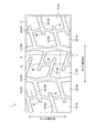
図2は、図1のA−A矢視図である。トレッド面3に形成される周方向溝20としては、タイヤ赤道面CLを挟んでタイヤ幅方向におけるタイヤ赤道面CLの両側に配設され、タイヤ周方向に延びる一対の内側周方向溝21と、タイヤ幅方向において一対の内側周方向溝21のそれぞれの外側に配設され、タイヤ周方向に延びる一対の外側周方向溝25とが設けられている。つまり、内側周方向溝21は、2本の内側周方向溝21がタイヤ幅方向におけるタイヤ赤道面CLの両側に配設され、外側周方向溝25は、2本の外側周方向溝25がタイヤ幅方向において2本の内側周方向溝21を挟んで2本の内側周方向溝21のタイヤ幅方向における両側に配設されている。これらの内側周方向溝21と外側周方向溝25とは、それぞれタイヤ幅方向に振幅しつつタイヤ周方向に延びて形成されている。
FIG. 2 is an AA arrow view of FIG. The
なお、内側周方向溝21は、溝幅が6mm以上15mm以下の範囲内になっており、溝深さが10mm以上18mm以下の範囲内になっている。また、外側周方向溝25は、溝幅が4mm以上12mm以下の範囲内になっており、溝深さが6mm以上18mm以下の範囲内になっている。また、内側周方向溝21と外側周方向溝25とは、外側周方向溝25の溝幅W2(図5参照)よりも、内側周方向溝21の溝幅W1(図5参照)の方が大きくなっている。詳しくは、内側周方向溝21と外側周方向溝25とは、内側周方向溝21の溝幅W1と外側周方向溝25の溝幅W2との関係が0.5≦(W2/W1)≦0.9になっており、即ち、(W2/W1)が0.5以上0.9以下となる関係になっている。また、内側周方向溝21の溝幅W1と外側周方向溝25の溝幅W2との関係は、好ましくは0.6≦(W2/W1)≦0.8の範囲内であるのが好ましい。
The inner
トレッド面3には、周方向溝20の他に、タイヤ幅方向に延びるラグ溝30が複数設けられている。ラグ溝30としては、センターラグ溝31と中間ラグ溝35とショルダーラグ溝36とが設けられている。このうち、センターラグ溝31は、タイヤ幅方向における一対の内側周方向溝21同士の間に配設されて、両端が一対の内側周方向溝21に接続されるラグ溝30になっている。また、中間ラグ溝35は、タイヤ幅方向において隣り合う内側周方向溝21と外側周方向溝25との間に配設され、両端が内側周方向溝21と外側周方向溝25とに接続されるラグ溝30になっている。また、ショルダーラグ溝36は、外側周方向溝25のタイヤ幅方向における外側に配設され、一端が外側周方向溝25に接続されるラグ溝30になっている。これらのセンターラグ溝31、中間ラグ溝35、ショルダーラグ溝36は、それぞれ複数がタイヤ周方向に並んで設けられている。
In addition to the
なお、センターラグ溝31は、溝幅が4mm以上9mm以下の範囲内になっており、溝深さが9mm以上18mm以下の範囲内になっている。また、中間ラグ溝35は、溝幅が4mm以上9mm以下の範囲内になっており、溝深さが2mm以上16mm以下の範囲内になっている。また、ショルダーラグ溝36は、溝幅が4mm以上16mm以下の範囲内になっており、溝深さが2mm以上16mm以下の範囲内になっている。
The
センターラグ溝31と中間ラグ溝35とは、共通の内側周方向溝21に接続されるが、内側周方向溝21に接続される部分のタイヤ周方向における位置が、センターラグ溝31と中間ラグ溝35とで異なっている。同様に、中間ラグ溝35とショルダーラグ溝36とは、共通の外側周方向溝25に接続されるが、外側周方向溝25に接続される部分のタイヤ周方向における位置が、中間ラグ溝35とショルダーラグ溝36とで異なっている。
The
トレッド面3に形成される陸部10は、これらの複数のラグ溝30と複数の周方向溝20とにより、センターブロック11と中間ブロック12とショルダーブロック13とが画成されている。このうち、センターブロック11は、隣り合うセンターラグ溝31と一対の内側周方向溝21とにより画成される陸部10になっており、これにより、センターブロック11は、タイヤ赤道面CL上に位置している。また、中間ブロック12は、隣り合う内側周方向溝21及び外側周方向溝25と、隣り合う中間ラグ溝35とにより画成される陸部10になっている。また、ショルダーブロック13は、タイヤ幅方向における外側周方向溝25の外側に設けられ、隣り合うショルダーラグ溝36により区画されると共にタイヤ幅方向における内側部分が外側周方向溝25によって区画される陸部10になっている。即ち、ショルダーブロック13は、外側周方向溝25とショルダーラグ溝36とにより画成される。これらのセンターブロック11、中間ブロック12、ショルダーブロック13は、それぞれ複数がタイヤ周方向に並んで設けられている。
In the
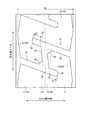
図3は、図2のB部詳細図である。陸部10を区画するラグ溝30のうち、センターラグ溝31は、複数の位置で屈曲することにより、タイヤ周方向に延びる周方向延在部33と、タイヤ幅方向に延びる幅方向延在部34とを有している。具体的には、1つのセンターラグ溝31は、屈曲する部分である屈曲部32を2箇所有しており、2箇所の屈曲部32で屈曲することによりクランク状の形状で形成されている。センターラグ溝31は、この2箇所の屈曲部32に挟まれた位置が、周方向延在部33として形成されている。周方向延在部33は、タイヤ赤道面CL上に形成されており、タイヤ周方向に対して所定の範囲内でタイヤ幅方向に傾斜している。タイヤ周方向に対する周方向延在部33の傾斜角度は、0°以上15°以下の範囲内になっている。なお、周方向延在部33は、全ての部分がタイヤ赤道面CL上に位置していなくてもよく、一部の位置がタイヤ赤道面CL上に位置し、他の部分はタイヤ赤道面CL上に位置していなくてもよい。
FIG. 3 is a detailed view of part B of FIG. Of the
また、幅方向延在部34は、周方向延在部33の端部からタイヤ幅方向に延びることにより、周方向延在部33の端部と内側周方向溝21、即ち、屈曲部32と内側周方向溝21とを接続している。詳しくは、幅方向延在部34は、各センターラグ溝31の2箇所に設けられており、2箇所の幅方向延在部34は、互いに異なる屈曲部32と、一対の内側周方向溝21における異なる内側周方向溝21とを接続している。2箇所の幅方向延在部34は、それぞれタイヤ幅方向に延びつつ、タイヤ周方向における同じ方向に傾斜している。詳しくは、幅方向延在部34は、当該幅方向延在部34と共に屈曲部32を構成する周方向延在部33が、タイヤ幅方向に対してタイヤ周方向に傾斜する側と同じ側に、周方向延在部33の傾斜角度とは異なる角度で傾斜している。また、1つのセンターラグ溝31が有する2箇所の幅方向延在部34の、タイヤ幅方向に対する傾斜角度は、ほぼ同じ角度になっている。
The
また、センターブロック11におけるセンターラグ溝31の屈曲部32の劣角側の位置には、トレッド面3から凹むことにより形成される屈曲部凹部40が設けられている。この屈曲部凹部40は、屈曲部32を構成する周方向延在部33と幅方向延在部34との双方に接続されており、周方向延在部33及び幅方向延在部34から連続して、トレッド面3から凹んで形成されている。屈曲部凹部40は、センターブロック11における屈曲部32の劣角側の部分に施される面取りにより形成されており、屈曲部凹部40の深さ方向に見た場合に、屈曲部32を1つの角とし、周方向延在部33に接続される部分と幅方向延在部34に接続される部分とをそれぞれ辺とする略三角形の形状で形成されている。
Further, a
つまり、屈曲部凹部40は、トレッド面3における屈曲部32の劣角側の部分が、屈曲部32から所定の大きさで周方向延在部33と幅方向延在部34との間にかけて除去されることにより構成されている。本実施形態では、屈曲部凹部40は、周方向延在部33に接続される部分と幅方向延在部34に接続される部分とが等しい長さで形成されている。なお、屈曲部凹部40は、トレッド面3からの深さが、1mm以上8mm以下の範囲内で形成されており、センターラグ溝31の溝深さの10%以上50%以下の範囲内で形成されている。
That is, the bent portion
また、センターブロック11には、幅方向延在部34の延長線上に設けられると共に、一端が屈曲部32に接続され、他端がセンターブロック11内で終端するセンター切欠き部45が形成されている。このセンター切欠き部45は、溝幅が幅方向延在部34の溝幅と同じ大きさで、溝深さが幅方向延在部34の溝深さと同じ深さとなる溝状の形状で形成されている。このため、換言すると、幅方向延在部34とセンター切欠き部45と周方向延在部33とは、幅方向延在部34とセンター切欠き部45とからなる1つの溝の途中に、周方向延在部33の端部が接続された形態で構成されている。
Further, the
これらのように、センターラグ溝31の屈曲部32に接続されるセンター切欠き部45は、幅方向延在部34の形成方向に沿った方向の長さELが、タイヤ幅方向におけるセンターブロック11の幅Wの10%以上20%以下の範囲内で形成されている。この場合におけるセンター切欠き部45の長さELは、屈曲部32を構成する周方向延在部33と幅方向延在部34とにおける、優角側の辺同士の接続部分から、センター切欠き部45の延在方向における長さになっている。
As described above, the
また、センター切欠き部45と屈曲部凹部40とは、共通の屈曲部32に接続される屈曲部凹部40の開口面積A1とセンター切欠き部45の開口面積A2との関係が3≦(A2/A1)≦6になっており、即ち、(A2/A1)が3以上6以下となる関係になっている。
Further, the
図4は、屈曲部空間部についての説明図である。さらに、センター切欠き部45は、周方向延在部33及び幅方向延在部34と、屈曲部凹部40とからなる屈曲部空間部42の開口面積A3と、センター切欠き部45の開口面積A2との関係が、0.03≦(A2/A3)≦0.10の範囲内になるように形成されている。この場合における屈曲部空間部42は、屈曲部凹部40の形状である三角形の屈曲部32側の角部に対向する辺41を、周方向延在部33と幅方向延在部34とにおける、屈曲部凹部40が位置する側の溝壁に対向する溝壁33a,34aまで延長することにより形成される空間部になっている。
FIG. 4 is an explanatory diagram of the bent space portion. Further, the
つまり、屈曲部空間部42は、延長した屈曲部凹部40の辺41と、周方向延在部33と幅方向延在部34とにおける屈曲部凹部40が位置する側の溝壁に対向する溝壁33a,34aをそれぞれ辺とする三角形状の空間部になっている。センター切欠き部45は、この屈曲部空間部42の開口面積A3と、センター切欠き部45の開口面積A2との比率(A2/A3)が、0.03以上0.10以下となる関係になっている。
In other words, the bent
本実施形態に係る空気入りタイヤ1は、タイヤ周方向における両側がセンターラグ溝31によって区画されるセンターブロック11とセンターラグ溝31とが主に含まれる領域であるセンター領域CA内の接地面積比率が、30%以上70%以下の範囲内で形成されている。この場合におけるセンター領域CAは、タイヤ幅方向におけるセンターブロック11の中心であるセンターブロック中心BCを中心とし、センターブロック11のタイヤ幅方向における幅Wの10%の領域になっている。即ち、センター領域CAは、センターブロック中心BCからタイヤ幅方向における両側に、タイヤ幅方向におけるセンターブロック11の幅Wのそれぞれ5%となる範囲の領域になっている。
In the pneumatic tire 1 according to the present embodiment, the contact area ratio in the center area CA, which is an area mainly including the
また、この場合におけるセンターブロック中心BCは、センターブロック11のタイヤ幅方向における両側で、タイヤ幅方向において最も外方側に位置する部分同士のタイヤ幅方向における中心となる位置をいう。本実施形態に係る空気入りタイヤでは、センターブロック中心BCは、タイヤ赤道面CL上に位置しており、センターブロック中心BCは、タイヤ幅方向における位置がタイヤ赤道面CLの位置と同じ位置になっている。また、センターブロック11の幅Wは、センターブロック11のタイヤ幅方向における両側で、タイヤ幅方向において最も外方側に位置する部分同士のタイヤ幅方向における距離になっている。
Further, the center block center BC in this case refers to the center position in the tire width direction of the portions located on the outermost side in the tire width direction on both sides of the
また、接地面積比率は、センター領域CAの面積に対する、実際に接地するトレッド面3の面積をいう。センターラグ溝31が有する周方向延在部33は、センター領域CA内に位置している。実際に空気入りタイヤ1が接地する際には、空気入りタイヤ1はタイヤ周方向上におけるいずれかの位置が接地し、接地面積比率は接地する部分ごとに異なるが、いずれの位置が接地した場合においても、センター領域CA内の接地面比率は、30%以上70%以下の範囲内になっている。また、センター領域CA内の接地面比率は、好ましくは40%以上60%以下の範囲内であるのが好ましい。
The ground contact area ratio refers to the area of the
また、センターブロック11は、タイヤ幅方向における幅Wが、トレッド展開幅TWの20%以上40%以下の範囲内で形成されている。この場合におけるトレッド展開幅TWは、空気入りタイヤ1を規定リムにリム組みして規定内圧で空気入りタイヤ1内に空気を充填し、荷重を加えない無負荷状態のときの、トレッド部2の展開図におけるタイヤ幅方向の両端の直線距離をいう。
Further, the
なお、規定リムとは、JATMAに規定される「適用リム」、TRAに規定される「Design Rim」、或いはETRTOに規定される「Measuring Rim」をいう。また、規定内圧とは、JATMAに規定される「最高空気圧」、TRAに規定される「TIRE LOAD LIMITS AT VARIOUS COLD INFLATION PRESSURES」の最大値、或いはETRTOで規定される「INFLATION PRESSURES」をいう。また、センターブロック11のタイヤ幅方向における幅Wは、好ましくはトレッド展開幅TWの25%以上35%以下の範囲内であるのが好ましい。
The specified rim refers to “applied rim” defined in JATMA, “Design Rim” defined in TRA, or “Measuring Rim” defined in ETRTO. The specified internal pressure refers to the “maximum air pressure” specified in JATMA, the maximum value of “TIRE LOAD LIMITS AT VARIOUS COLD INFLATION PRESSURES” specified in TRA, or “INFLATION PRESSURES” specified in ETRTO. The width W of the
また、センターブロック11は、タイヤ周方向における長さLとタイヤ幅方向における幅Wとの比率が、0.9≦(L/W)≦1.1の範囲内となって形成されている。つまり、センターブロック11は、タイヤ周方向における長さLが、タイヤ幅方向における幅Wに対して0.9倍以上1.1倍以下となる形状で形成されている。この場合におけるセンターブロック11の長さLは、センターブロック11における、タイヤ周方向において最も離間している部分同士のタイヤ周方向における距離になっている。
The
また、センターブロック11は、面積が中間ブロック12やショルダーブロック13の面積よりも大きくなっている。換言すると、中間ブロック12やショルダーブロック13は、センターブロック11よりも面積が小さくなっており、例えば、ショルダーブロック13は、面積が、センターブロック11の面積の40%以上60%以下の範囲内となって形成されている。なお、センターブロック11の面積に対するショルダーブロック13の面積は、45%以上55%以下であるのが好ましい。
The
センターブロック11は、タイヤ幅方向における幅Wが、ベルト層7のタイヤ幅方向における最大幅である最大ベルト幅BWの25%以上45%以下の範囲内となって形成されている。ここでいう最大ベルト幅BWは、ベルト層7を構成する複数のベルト71,72,73,74のタイヤ幅方向両側のそれぞれの端部において、タイヤ幅方向における位置が最も外方側に位置する端部同士のタイヤ幅方向における距離になっている。また、最大ベルト幅BWに対するセンターブロック11のタイヤ幅方向における幅Wは、好ましくは30%以上40%以下の範囲内であるのが好ましい。
The
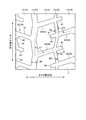
図5は、図2のC部詳細図である。また、中間ラグ溝35とショルダーラグ溝36とは、共にタイヤ幅方向に対して、タイヤ周方向に傾斜している。詳しくは、中間ラグ溝35は、タイヤ幅方向に対するタイヤ周方向への傾斜角度が、0°以上15°以下の範囲内で形成されている。換言すると、中間ラグ溝35は、タイヤ周方向に対するタイヤ幅方向への傾斜角度α1が、75°以上105°以下の範囲内で形成されており、即ち、中間ラグ溝35は、タイヤ周方向に対するタイヤ幅方向への傾斜角度α1が90°±15°の範囲内で形成されている。なお、タイヤ周方向に対する中間ラグ溝35の傾斜角度α1は、好ましくは90°±10°の範囲内であるのが好ましい。
FIG. 5 is a detailed view of part C of FIG. The
また、ショルダーラグ溝36は、タイヤ幅方向に対するタイヤ周方向への傾斜方向が、中間ラグ溝35のタイヤ幅方向に対するタイヤ周方向への傾斜方向と同じ方向になっている。これらの中間ラグ溝35とショルダーラグ溝36とは、中間ラグ溝35の、タイヤ周方向に対するタイヤ幅方向への傾斜角度α1と、ショルダーラグ溝36の、タイヤ周方向に対するタイヤ幅方向への傾斜角度α2と、の関係が、0°≦|α2−α1|≦10°の範囲内となって形成されている。
The
また、中間ブロック12には、外側周方向溝25に接続される中間切欠き部46が形成され、ショルダーブロック13には、外側周方向溝25に接続されるショルダー切欠き部47が形成されている。このうち、中間切欠き部46は、外側周方向溝25における中間切欠き部46が接続される側の反対側に接続されるショルダーラグ溝36の延長線上に設けられており、一端が外側周方向溝25に接続され、他端が中間ブロック12内で終端して形成されている。この中間切欠き部46は、ショルダーラグ溝36の延在方向における長さMLが、外側周方向溝25の溝幅W2の150%以上300%以下の範囲内で形成されている。
Further, the
また、ショルダー切欠き部47は、外側周方向溝25におけるショルダー切欠き部47が接続される側の反対側に接続される中間ラグ溝35の延長線上に設けられており、一端が外側周方向溝25に接続され、他端がショルダーブロック13内で終端して形成されている。このショルダー切欠き部47は、中間ラグ溝35の延在方向における長さSLが、外側周方向溝25の溝幅W2の100%以上300%以下の範囲内で形成されている。
Further, the
これらのように構成される本実施形態に係る空気入りタイヤ1は、用途が重荷重用空気入りタイヤになっている。この空気入りタイヤ1を車両に装着する際には、リムホイールにリム組みしてインフレートした状態で車両に装着する。リムホイールにリム組みした状態の空気入りタイヤ1は、例えばトラックやバス等の大型の車両に装着して使用される。 The pneumatic tire 1 according to the present embodiment configured as described above is used for a heavy-duty pneumatic tire. When the pneumatic tire 1 is mounted on the vehicle, the pneumatic tire 1 is mounted on the vehicle in a rim-assembled and inflated state. The pneumatic tire 1 in a rim assembled state with a rim wheel is used by being mounted on a large vehicle such as a truck or a bus.
空気入りタイヤ1を装着した車両が走行すると、トレッド面3のうち下方に位置するトレッド面3が路面に接触しながら当該空気入りタイヤ1は回転する。車両は、トレッド面3と路面との間の摩擦力により、駆動力や制動力を路面に伝達したり、旋回力を発生させたりすることにより走行する。このため、空気入りタイヤ1の接地領域における接地面積は、車両の走行時における操縦安定性に対して重要な要素となる。一方で、雪道を走行する際には、周方向溝20やラグ溝30での雪柱せん断力やエッジ効果を多用して走行するため、接地領域における溝面積も重要な要素になる。
When the vehicle equipped with the pneumatic tire 1 travels, the pneumatic tire 1 rotates while the
また、トラックやバス等の大型の車両では、貨物の積載状態によって車両の総重量が大きく変化し、これに伴い、空気入りタイヤ1に作用する荷重も大きく変化する。空気入りタイヤ1に作用する荷重が大きく変化した場合、空気入りタイヤ1の接地領域の形状が変化し、荷重が大きくなるに従って接地領域が大きくなる。つまり、空気入りタイヤ1に作用する荷重が大きくなるに従って、空気入りタイヤ1の接地領域は、タイヤ幅方向とタイヤ周方向とのいずれの方向にも大きくなる。 Further, in a large vehicle such as a truck or a bus, the total weight of the vehicle greatly varies depending on the cargo loading state, and accordingly, the load acting on the pneumatic tire 1 also varies greatly. When the load acting on the pneumatic tire 1 changes greatly, the shape of the ground contact area of the pneumatic tire 1 changes, and the ground contact area increases as the load increases. That is, as the load acting on the pneumatic tire 1 increases, the contact area of the pneumatic tire 1 increases in both the tire width direction and the tire circumferential direction.
しかし、トレッド面3のタイヤ幅方向における中心付近、即ち、トレッド面3におけるタイヤ赤道面CL付近は、空気入りタイヤ1に作用する荷重の大きさに関わらず、車両の走行時に接地する。本実施形態に係る空気入りタイヤ1は、タイヤ赤道面CLの両側に内側周方向溝21が配設されてタイヤ赤道面CL上にセンターブロック11が位置することにより、タイヤ赤道面CL付近の接地面積が確保されている。これにより、空気入りタイヤ1に作用する荷重の大きさに関わらず、乾燥した路面を走行する際における操縦安定性を確保することができる。
However, the vicinity of the center of the
また、センターラグ溝31は、複数の位置で屈曲することにより、タイヤ赤道面CL上に周方向延在部33を有しているため、雪道を走行する際におけるタイヤ赤道面CL付近での雪柱せん断力やエッジ効果が確保されている。さらに、センターラグ溝31には、屈曲部32の劣角側の位置に屈曲部凹部40が接続されているため、雪が詰まり易い部分である屈曲部32近傍の排雪性を向上させることができる。これらにより、空気入りタイヤ1に作用する荷重の大きさに関わらず、雪道を走行する際における接地面と雪面との間の抵抗を、継続的に確保することができる。また、センターラグ溝31には周方向延在部33が形成されているため、タイヤ赤道面CL付近における、タイヤ幅方向に対するエッジ成分を増加させることができる。これにより、加速時のスリップに対する空気入りタイヤ1の横滑りを低減することができ、また、雪道を走行する際における操縦安定性を向上させることができる。
Further, the
さらに、トレッド面3は、センター領域CA内の接地面積比率が30%以上70%以下であるため、空気入りタイヤ1に作用する荷重の大きさに関わらず、乾燥した路面を走行する際における接地面積を確保することができ、且つ、雪道を走行する際における雪面と接地面との間の抵抗を確保することができる。つまり、センター領域CA内の接地面積比率が30%未満の場合は、荷重が小さい場合における接地面積が小さくなるため、操縦安定性の確保が困難になり、センター領域CA内の接地面積比率が70%を超える場合は、荷重が小さい場合における溝面積が小さくなるため、接地面と雪面との間の抵抗の確保が困難になる。これに対し、本実施形態に係る空気入りタイヤ1は、センター領域CA内の接地面積比率が30%以上70%以下の範囲内で形成されているため、空気入りタイヤ1に作用する荷重が小さい場合における接地面積を確保しつつ、接地面と雪面との間の抵抗を確保することができる。これらの結果、貨物の積載状態に関わらず、即ち、空車や積車に関わらず、ドライ性能とスノー性能とを共に向上させることができ、特に、空車時のドライ性能とスノー性能とを向上させることができる。
Further, the
また、センターラグ溝31の周方向延在部33は、センター領域CA内に位置するため、タイヤ赤道面CL上に位置するセンターブロック11を設けた場合における、センター領域CA内の溝面積を確保することができる。これにより、タイヤ赤道面CL上にセンターブロック11を配設することによって空車時のドライ性能を確保した場合における、空車時の接地面と雪面との間の抵抗を確保することができる。この結果、より確実にドライ性能とスノー性能とを共に向上させることができる。
Further, since the
また、屈曲部凹部40は、面取りにより形成されるため、ブロック剛性が低くなり易いセンターラグ溝31の屈曲部32の劣角側の部分に、センターブロック11の剛性を低下させることなく、屈曲部凹部40を設けることができる。これにより、排雪性を向上させるために屈曲部凹部40を設ける場合におけるドライ性能の低下を抑制することができ、ドライ性能とスノー性能とを、より確実に共に向上させることができる。
Further, since the bent portion
また、屈曲部凹部40は、センターラグ溝31の周方向延在部33に接続される部分と幅方向延在部34に接続される部分とが等しい長さで形成されるため、屈曲部凹部40を設けることに起因してセンターブロック11の剛性を低下させることなく、屈曲部凹部40を設けることができる。これにより、排雪性を向上させるために屈曲部凹部40を設ける場合におけるドライ性能の低下を抑制することができ、ドライ性能とスノー性能とを、より確実に共に向上させることができる。
Further, the
また、屈曲部凹部40は、トレッド面3からの深さがセンターラグ溝31の溝深さの10%以上50%以下の範囲内で形成されるため、より確実にドライ性能とスノー性能とを両立することができる。つまり、屈曲部凹部40の深さがセンターラグ溝31の溝深さの10%未満の場合は、屈曲部凹部40の深さが浅すぎ、センターラグ溝31の溝深さとの差が大きすぎるため、センターラグ溝31に入り込んだ雪を効果的に排雪するのが困難になる虞がある。また、屈曲部凹部40の深さがセンターラグ溝31の溝深さの50%を超える場合は、センターブロック11における屈曲部凹部40の近傍の剛性が低下し、ドライ性能を確保し難くなる虞がある。これに対し、屈曲部凹部40の深さをセンターラグ溝31の溝深さの10%以上50%以下の範囲内にした場合には、センターブロック11の剛性を低下させることなく、屈曲部凹部40での排雪性を確保することができる。この結果、より確実にドライ性能とスノー性能とを共に向上させることができる。
Moreover, since the depth from the
また、センターブロック11には、センターラグ溝31の屈曲部32に接続されるセンター切欠き部45が形成されているため、センター切欠き部45によっても雪柱せん断力やエッジ効果を確保することができる。これにより、センター領域CA付近での接地面と雪面との間の抵抗を、より確実に高めることができ、スノー性能を、より確実に向上させることができる。
Further, since the
また、センター切欠き部45は、センターラグ溝31の幅方向延在部34の形成方向に沿った方向の長さELが、センターブロック11の幅Wの10%以上20%以下の範囲内で形成されているため、ドライグリップに寄与する接地面積を充分に確保しつつ、雪上でのトラクション性能を向上させることができる。つまり、センター切欠き部45の長さELがセンターブロック11の幅Wの10%未満の場合は、センター切欠き部45での雪柱せん断力やエッジ効果があまり高くないため、接地面と雪面との間の抵抗を効果的に向上させるのが困難になる。また、センター切欠き部45の長さELがセンターブロック11の幅Wの20%を超える場合は、センターブロック11の接地面積が小さくなり過ぎる虞がある。これに対し、センター切欠き部45の長さELをセンターブロック11の幅Wの10%以上20%以下の範囲内にした場合には、雪柱せん断力やエッジ効果が期待できるセンター切欠き部45を、センターブロック11の接地面積を小さくし過ぎることなく設けることができる。この結果、より確実にドライ性能とスノー性能とを共に向上させることができる。
Further, the
また、屈曲部凹部40とセンター切欠き部45とは、共通の屈曲部32に接続される屈曲部凹部40の開口面積A1とセンター切欠き部45の開口面積A2との関係が3≦(A2/A1)≦6であるため、センターブロック11の剛性を均一にすることができる。つまり、屈曲部凹部40とセンター切欠き部45とは、タイヤ幅方向におけるセンターラグ溝31の周方向延在部33の両側に配設されているため、(A2/A1)が3未満であったり、(A2/A1)が6を超えたりする場合は、センターブロック11における周方向延在部33の両側の剛性差が大きくなり過ぎ、偏摩耗の原因となる虞がある。これに対し、屈曲部凹部40の開口面積A1とセンター切欠き部45の開口面積A2との関係を3≦(A2/A1)≦6の範囲内にした場合には、周方向延在部33の両側の剛性差を小さくすることができる。この結果、屈曲部凹部40とセンター切欠き部45とを設けた場合における偏摩耗の発生を抑制することができる。
In addition, the bending
また、中間ブロック12には中間切欠き部46が形成され、ショルダーブロック13にはショルダー切欠き部47が形成されているため、中間切欠き部46とショルダー切欠き部47との雪柱せん断力やエッジ効果により、接地領域のタイヤ幅方向における両端付近での、接地面と雪面との間の抵抗を大きくすることができる。この結果、スノー加速性能を向上させることができ、スノー性能をより確実に向上させることができる。
Further, since the
また、中間ラグ溝35は、タイヤ周方向に対するタイヤ幅方向への傾斜角度α1が、75°以上105°以下の範囲内で形成されているため、接地領域のタイヤ幅方向における両端付近での、タイヤ周方向に対するエッジ成分を向上させることができる。この結果、より確実にスノー性能を向上させることができる。
Further, the
また、中間ラグ溝35とショルダーラグ溝36とは、中間ラグ溝35の傾斜角度α1とショルダーラグ溝36の傾斜角度α2との関係が、0°≦|α2−α1|≦10°の範囲内であるため、排雪性を確保することができ、また、中間ラグ溝35やショルダーラグ溝36での雪柱せん断力やエッジ効果を効果的に高めることができる。この結果、より確実にスノー性能を向上させることができる。
The
また、内側周方向溝21と外側周方向溝25とは、内側周方向溝21の溝幅W1と外側周方向溝25の溝幅W2との関係が0.5≦(W2/W1)≦0.9の関係を満たして形成されるため、センター領域CA寄りの位置の溝面積を確保することができ、排雪性を充分に発揮することができる。この結果、ドライ性能を向上させつつ、空車時のスノー性能を向上させることができる。
The inner
また、センターブロック11は、タイヤ幅方向における幅Wが、トレッド展開幅TWの20%以上40%以下となって形成されるため、センター領域CAの溝面積を確保しつつ、センターブロック11の面積を大きく取ることができる。この結果、スノー性能を確保しつつ、ドライ性能を向上させることができる。
Further, since the
また、センターブロック11は、タイヤ周方向における長さLとタイヤ幅方向における幅Wとの比率が、0.9≦(L/W)≦1.1の範囲内で形成されているため、センターブロック11の剛性を確保することができ、操縦安定性を確保することができる。つまり、(L/W)が0.9未満であったり、1.1よりも大きかったりすると、センターブロック11のタイヤ周方向における剛性やタイヤ幅方向における剛性が低くなり過ぎる虞があり、センターブロック11が倒れ易くなるため、センターブロック11の有効接地面積が低下する虞がある。これに対し、センターブロック11のタイヤ周方向における長さLとタイヤ幅方向における幅Wとの比率を、0.9≦(L/W)≦1.1の範囲内にすることにより、センターブロック11の剛性を確保することができるため、センターブロック11の有効接地面積が低下することを抑制することができる。この結果、より確実にドライ性能とスノー性能とを共に向上させることができる。
The
また、ショルダーブロック13の面積が、センターブロック11の面積の40%以上60%以下の範囲内となって形成されているため、空車時にはセンター領域CAと比較して接地する頻度が少ないショルダー領域の溝面積を確保することができ、雪柱せん断力やエッジ効果を確保することができる。また、ショルダーブロック13の面積に対してセンターブロック11の面積を大きくすることにより、センターブロック11の剛性を確保することができる。これにより、センターブロック11の剛性が低いことに起因してセンターブロック11の有効接地面積が低下することを抑制することができる。この結果、より確実にドライ性能とスノー性能とを共に向上させることができる。
Further, since the area of the
また、センターブロック11は、タイヤ幅方向における幅Wが、最大ベルト幅BWの25%以上45%以下の範囲内となって形成されているため、タイヤ幅方向において、センター領域CAを中心とする接地圧が高い領域でのベルト層7の幅の最適化を図ることができる。これにより、タイヤ幅方向におけるトレッド部2の剛性の均一化を図ることができる。この結果、車両の走行状態に関わらず、操縦安定性を向上させることができる。
Further, since the
また、カーカス6にスチールカーカス材を使用するため、空気入りタイヤ1全体の剛性を確保することができる。この結果、車両の走行状態に関わらず、操縦安定性を向上させることができる。 Moreover, since a steel carcass material is used for the carcass 6, the rigidity of the entire pneumatic tire 1 can be ensured. As a result, the steering stability can be improved regardless of the running state of the vehicle.
また、本実施形態に係る空気入りタイヤ1を重荷重用空気入りタイヤとして用いることにより、貨物の積載状態により空気入りタイヤ1に作用する荷重が大きく変化する場合でも、荷重の大きさに関わらず、ドライ性能とスノー性能とを共に向上させることができる。この結果、本実施形態に係る空気入りタイヤ1をトラックやバス等の大型の車両に装着した場合における車両の走行性能を向上させることができる。 In addition, by using the pneumatic tire 1 according to the present embodiment as a heavy duty pneumatic tire, even when the load acting on the pneumatic tire 1 varies greatly depending on the cargo loading state, regardless of the magnitude of the load, Both dry performance and snow performance can be improved. As a result, the running performance of the vehicle when the pneumatic tire 1 according to the present embodiment is mounted on a large vehicle such as a truck or a bus can be improved.
〔実施例〕
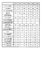
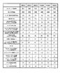
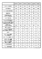
図6A〜図6Dは、空気入りタイヤの性能試験の結果を示す図表である。以下、上記の空気入りタイヤ1について、従来例の空気入りタイヤ1と、本発明に係る空気入りタイヤ1とについて行なった性能の評価試験について説明する。性能評価試験は、乾燥した路面での加速性能であるドライ加速性能についての試験と、雪上での加速性能であるスノー加速性能についての試験とについて行った。
〔Example〕
6A to 6D are tables showing results of performance tests of pneumatic tires. Hereinafter, the performance evaluation test performed on the pneumatic tire 1 according to the related art and the pneumatic tire 1 according to the present invention will be described. In the performance evaluation test, a test for dry acceleration performance, which is acceleration performance on a dry road surface, and a test for snow acceleration performance, which is acceleration performance on snow, were performed.
これらの性能評価試験は、JATMAで規定されるタイヤの呼びが275/80R22.5サイズでロードインデックスが151Jの空気入りタイヤ1をJATMAで規定される規定リムのリムホイールにリム組みし、空気圧をJATMAで規定される最大空気圧に調整し、2−Dの試験車両(トラクターヘッド)に装着してテスト走行をすることにより行った。 In these performance evaluation tests, a pneumatic tire 1 with a tire size specified by JATMA of 275 / 80R22.5 size and a road index of 151J is assembled on a rim wheel of a specified rim specified by JATMA, and the air pressure is increased. The test was carried out by adjusting the maximum air pressure specified by JATMA and mounting it on a 2-D test vehicle (tractor head).
各試験項目の評価方法は、ドライ加速性能については、ドライ路面での5〜40km/hの速度区間の加速度を測定し、平均加速度を指数化することによって評価した。数値が大きいほどドライ加速性能が優れていることを示している。スノー加速性能については、圧雪路面での5〜20km/hの速度区間の加速度を測定し、平均加速度を指数化することによって評価した。数値が大きいほどスノー加速性能が優れていることを示している。また、ドライ加速性能とスノー加速性能は、それぞれ指数が105以上である場合、有効な性能を有しているものとする。 The evaluation method of each test item evaluated the dry acceleration performance by measuring the acceleration in the speed section of 5 to 40 km / h on the dry road surface and indexing the average acceleration. The larger the value, the better the dry acceleration performance. The snow acceleration performance was evaluated by measuring the acceleration in the speed section of 5 to 20 km / h on the snowy road surface and indexing the average acceleration. The larger the value, the better the snow acceleration performance. Further, it is assumed that the dry acceleration performance and the snow acceleration performance have effective performance when the index is 105 or more.
評価試験は、従来の空気入りタイヤ1の一例である従来例1〜3の空気入りタイヤ1と、本発明に係る空気入りタイヤ1である実施例1〜21の24種類の空気入りタイヤ1について行った。これらの空気入りタイヤ1は、センターラグ溝31が屈曲しているか否か、周方向溝20がタイヤ幅方向に振幅しているか否か、センター領域CA内の接地面積比、屈曲部凹部40の有無がそれぞれ異なって形成されている。このうち、従来例1〜3の空気入りタイヤ1は、全て屈曲部凹部40が設けられておらず、センターラグ溝31が屈曲していない、または周方向溝20が振幅していない、またはセンター領域CA内の接地面積比が30%以上70%以下の範囲内に無いものになっている。
The evaluation test is performed on the 24 types of pneumatic tires 1 of Examples 1 to 21 that are the pneumatic tires 1 of the conventional examples 1 to 3 that are examples of the conventional pneumatic tire 1 and the pneumatic tire 1 according to the present invention. went. In these pneumatic tires 1, whether or not the
これに対し、本発明に係る空気入りタイヤ1の一例である実施例1〜21は、センターラグ溝31が屈曲し、周方向溝20が振幅しており、センター領域CA内の接地面積比が30%以上70%以下の範囲内になっており、屈曲部凹部40を有している。さらに、実施例1〜21に係る空気入りタイヤ1は、センター切欠き部45の有無や、センター切欠き部45の長さEL、屈曲部凹部40の開口面積A1に対するセンター切欠き部45の開口面積A2の割合、中間切欠き部46とショルダー切欠き部47の有無、中間ラグ溝35やショルダーラグ溝36の傾斜角度α1,α2、内側周方向溝21と外側周方向溝25の溝幅W1,W2の相対関係、トレッド展開幅TWに対するセンターブロック11の幅Wの割合、センターブロック11の縦横比、センターブロック11の面積に対するショルダーブロック13の面積の割合、最大ベルト幅BWに対するセンターブロック11の幅Wの割合が、それぞれ異なっている。
On the other hand, in Examples 1-21, which are examples of the pneumatic tire 1 according to the present invention, the
これらの空気入りタイヤ1を用いて評価試験を行った結果、図6A〜図6Dに示すように、実施例1〜21の空気入りタイヤ1は、従来例1〜3に対して、ドライ加速性能とスノー加速性能とが共に向上することが分かった。つまり、実施例1〜21に係る空気入りタイヤ1は、ドライ性能とスノー性能とを共に向上させることができる。 As a result of performing an evaluation test using these pneumatic tires 1, as shown in FIGS. 6A to 6D, the pneumatic tires 1 of Examples 1 to 21 have a dry acceleration performance compared to the conventional examples 1 to 3. And snow acceleration performance are improved. That is, the pneumatic tire 1 according to Examples 1 to 21 can improve both dry performance and snow performance.
1 空気入りタイヤ
2 トレッド部
3 トレッド面
4 ショルダー部
5 サイドウォール部
6 カーカス
7 ベルト層
8 インナーライナ
10 陸部
11 センターブロック
12 中間ブロック
13 ショルダーブロック
20 周方向溝
21 内側周方向溝
25 外側周方向溝
30 ラグ溝
31 センターラグ溝
32 屈曲部
33 周方向延在部
34 幅方向延在部
35 中間ラグ溝
36 ショルダーラグ溝
40 屈曲部凹部
42 屈曲部空間部
45 センター切欠き部
46 中間切欠き部
47 ショルダー切欠き部
50 ビード部
CL タイヤ赤道面
CA センター領域
DESCRIPTION OF SYMBOLS 1
Claims (15)
タイヤ幅方向において一対の前記内側周方向溝のそれぞれの外側に配設され、タイヤ周方向に延びる一対の外側周方向溝と、
両端が一対の前記内側周方向溝に接続されると共に、複数の位置で屈曲することによりタイヤ周方向に延びる周方向延在部とタイヤ幅方向に延びる幅方向延在部とを有する複数のセンターラグ溝と、
前記センターラグ溝と前記内側周方向溝とにより画成される陸部であるセンターブロックと、
前記センターブロックにおける前記センターラグ溝の屈曲部の劣角側の位置でトレッド面から凹むことにより形成され、且つ、前記周方向延在部と前記幅方向延在部とに接続される屈曲部凹部と、
を備え、
タイヤ幅方向における前記センターブロックの中心を中心とし、前記センターブロックのタイヤ幅方向における幅の10%の領域であるセンター領域内の接地面積比率が30%以上70%以下であることを特徴とする空気入りタイヤ。 A pair of inner circumferential grooves disposed on both sides of the tire equatorial plane in the tire width direction across the tire equatorial plane and extending in the tire circumferential direction;
A pair of outer circumferential grooves disposed on the outer sides of the pair of inner circumferential grooves in the tire width direction and extending in the tire circumferential direction;
A plurality of centers having both ends connected to the pair of inner circumferential grooves and having a circumferentially extending portion extending in the tire circumferential direction and a widthwise extending portion extending in the tire width direction by bending at a plurality of positions Lug grooves,
A center block which is a land portion defined by the center lug groove and the inner circumferential groove;
A bent portion recess formed by recessing from the tread surface at a position on the minor angle side of the bent portion of the center lug groove in the center block and connected to the circumferentially extending portion and the width extending portion. When,
With
Centering on the center of the center block in the tire width direction, the contact area ratio in the center region, which is a region of 10% of the width of the center block in the tire width direction, is 30% or more and 70% or less Pneumatic tire.
前記外側周方向溝のタイヤ幅方向における外側に配設され、一端が前記外側周方向溝に接続される複数のショルダーラグ溝と、
前記内側周方向溝と前記外側周方向溝と前記中間ラグ溝とにより画成される陸部である中間ブロックと、
前記外側周方向溝と前記ショルダーラグ溝とにより画成される陸部であるショルダーブロックと、
を備え、
前記中間ブロックには、前記ショルダーラグ溝の延長線上に設けられると共に一端が前記外側周方向溝に接続され、他端が中間ブロック内で終端する中間切欠き部が形成され、
前記ショルダーブロックには、前記中間ラグ溝の延長線上に設けられると共に一端が前記外側周方向溝に接続され、他端がショルダーブロック内で終端するショルダー切欠き部が形成される請求項1〜8のいずれか1項に記載の空気入りタイヤ。 A plurality of intermediate lug grooves whose both ends are connected to the adjacent inner circumferential groove and the outer circumferential groove;
A plurality of shoulder lug grooves disposed on the outer side in the tire width direction of the outer circumferential groove, one end of which is connected to the outer circumferential groove;
An intermediate block which is a land portion defined by the inner circumferential groove, the outer circumferential groove and the intermediate lug groove;
A shoulder block which is a land portion defined by the outer circumferential groove and the shoulder lug groove;
With
The intermediate block is formed on an extension line of the shoulder lug groove, and one end is connected to the outer circumferential groove, and the other end is formed with an intermediate notch that terminates in the intermediate block.
The shoulder block is formed on the extension line of the intermediate lug groove, and is formed with a shoulder notch portion having one end connected to the outer circumferential groove and the other end terminating in the shoulder block. The pneumatic tire according to any one of the above.
前記中間ラグ溝の、タイヤ周方向に対するタイヤ幅方向への傾斜角度α1と、
前記ショルダーラグ溝の、タイヤ周方向に対するタイヤ幅方向への傾斜角度α2と、
の関係が、0°≦|α2−α1|≦10°である請求項9または10に記載の空気入りタイヤ。 The intermediate lug groove and the shoulder lug groove are
An inclination angle α1 of the intermediate lug groove in the tire width direction with respect to the tire circumferential direction,
An inclination angle α2 of the shoulder lug groove in the tire width direction with respect to the tire circumferential direction;
The pneumatic tire according to claim 9 or 10, wherein the relationship is 0 ° ≦ | α2−α1 | ≦ 10 °.
Priority Applications (2)
| Application Number | Priority Date | Filing Date | Title |
|---|---|---|---|
| JP2016005757A JP6724373B2 (en) | 2016-01-15 | 2016-01-15 | Pneumatic tire |
| CN201710023977.9A CN106976362B (en) | 2016-01-15 | 2017-01-13 | Pneumatic tire |
Applications Claiming Priority (1)
| Application Number | Priority Date | Filing Date | Title |
|---|---|---|---|
| JP2016005757A JP6724373B2 (en) | 2016-01-15 | 2016-01-15 | Pneumatic tire |
Publications (2)
| Publication Number | Publication Date |
|---|---|
| JP2017124773A true JP2017124773A (en) | 2017-07-20 |
| JP6724373B2 JP6724373B2 (en) | 2020-07-15 |
Family
ID=59340254
Family Applications (1)
| Application Number | Title | Priority Date | Filing Date |
|---|---|---|---|
| JP2016005757A Active JP6724373B2 (en) | 2016-01-15 | 2016-01-15 | Pneumatic tire |
Country Status (2)
| Country | Link |
|---|---|
| JP (1) | JP6724373B2 (en) |
| CN (1) | CN106976362B (en) |
Cited By (6)
| Publication number | Priority date | Publication date | Assignee | Title |
|---|---|---|---|---|
| JP2019034661A (en) * | 2017-08-17 | 2019-03-07 | 東洋ゴム工業株式会社 | Pneumatic tire |
| JP2019194282A (en) * | 2018-05-01 | 2019-11-07 | 横浜ゴム株式会社 | Tire rubber composition and pneumatic tire |
| JP2019194038A (en) * | 2018-05-01 | 2019-11-07 | 横浜ゴム株式会社 | Pneumatic tire |
| CN111114206A (en) * | 2020-01-17 | 2020-05-08 | 安徽佳通乘用子午线轮胎有限公司 | Winter tire with crescent pattern blocks |
| WO2020170466A1 (en) * | 2019-02-20 | 2020-08-27 | 横浜ゴム株式会社 | Pneumatic tire |
| CN114641400A (en) * | 2019-10-29 | 2022-06-17 | 株式会社普利司通 | Pneumatic tires |
Families Citing this family (5)
| Publication number | Priority date | Publication date | Assignee | Title |
|---|---|---|---|---|
| JP6521110B1 (en) | 2018-01-23 | 2019-05-29 | 横浜ゴム株式会社 | Pneumatic tire |
| JP6658789B2 (en) * | 2018-04-17 | 2020-03-04 | 横浜ゴム株式会社 | Pneumatic tire |
| JP7312643B2 (en) * | 2019-08-07 | 2023-07-21 | Toyo Tire株式会社 | pneumatic tire |
| JP7291032B2 (en) * | 2019-08-07 | 2023-06-14 | Toyo Tire株式会社 | pneumatic tire |
| JP6888707B1 (en) * | 2020-03-04 | 2021-06-16 | 横浜ゴム株式会社 | tire |
Citations (9)
| Publication number | Priority date | Publication date | Assignee | Title |
|---|---|---|---|---|
| JPH02231204A (en) * | 1989-03-02 | 1990-09-13 | Bridgestone Corp | Anti-skid pattern of pneumatic tire |
| JP2000043512A (en) * | 1998-07-29 | 2000-02-15 | Bridgestone Corp | Pneumatic tire |
| JP2004098854A (en) * | 2002-09-10 | 2004-04-02 | Bridgestone Corp | Pneumatic tire |
| JP2006111122A (en) * | 2004-10-14 | 2006-04-27 | Bridgestone Corp | Pneumatic tire |
| JP2007161057A (en) * | 2005-12-13 | 2007-06-28 | Bridgestone Corp | Pneumatic tire |
| JP2010260471A (en) * | 2009-05-08 | 2010-11-18 | Bridgestone Corp | Pneumatic tire |
| JP2013103621A (en) * | 2011-11-14 | 2013-05-30 | Yokohama Rubber Co Ltd:The | Pneumatic tire |
| JP2015123936A (en) * | 2013-12-27 | 2015-07-06 | 住友ゴム工業株式会社 | Pneumatic tire |
| WO2015166803A1 (en) * | 2014-05-01 | 2015-11-05 | 横浜ゴム株式会社 | Pneumatic tire |
Family Cites Families (6)
| Publication number | Priority date | Publication date | Assignee | Title |
|---|---|---|---|---|
| JP4189980B2 (en) * | 1998-11-27 | 2008-12-03 | 株式会社ブリヂストン | Pneumatic tire |
| JP4377862B2 (en) * | 2005-08-04 | 2009-12-02 | 住友ゴム工業株式会社 | Heavy duty pneumatic tire |
| JP5595863B2 (en) * | 2010-10-12 | 2014-09-24 | 横浜ゴム株式会社 | Heavy duty pneumatic tire |
| JP5798586B2 (en) * | 2013-03-15 | 2015-10-21 | 住友ゴム工業株式会社 | Pneumatic tire |
| JP5941449B2 (en) * | 2013-09-24 | 2016-06-29 | 住友ゴム工業株式会社 | Pneumatic tire |
| CN203666285U (en) * | 2014-02-10 | 2014-06-25 | 波沃兹斯卡亚什纳亚库帕尼亚有限责任公司 | Tire tread structure and tire utilizing same |
-
2016
- 2016-01-15 JP JP2016005757A patent/JP6724373B2/en active Active
-
2017
- 2017-01-13 CN CN201710023977.9A patent/CN106976362B/en not_active Expired - Fee Related
Patent Citations (9)
| Publication number | Priority date | Publication date | Assignee | Title |
|---|---|---|---|---|
| JPH02231204A (en) * | 1989-03-02 | 1990-09-13 | Bridgestone Corp | Anti-skid pattern of pneumatic tire |
| JP2000043512A (en) * | 1998-07-29 | 2000-02-15 | Bridgestone Corp | Pneumatic tire |
| JP2004098854A (en) * | 2002-09-10 | 2004-04-02 | Bridgestone Corp | Pneumatic tire |
| JP2006111122A (en) * | 2004-10-14 | 2006-04-27 | Bridgestone Corp | Pneumatic tire |
| JP2007161057A (en) * | 2005-12-13 | 2007-06-28 | Bridgestone Corp | Pneumatic tire |
| JP2010260471A (en) * | 2009-05-08 | 2010-11-18 | Bridgestone Corp | Pneumatic tire |
| JP2013103621A (en) * | 2011-11-14 | 2013-05-30 | Yokohama Rubber Co Ltd:The | Pneumatic tire |
| JP2015123936A (en) * | 2013-12-27 | 2015-07-06 | 住友ゴム工業株式会社 | Pneumatic tire |
| WO2015166803A1 (en) * | 2014-05-01 | 2015-11-05 | 横浜ゴム株式会社 | Pneumatic tire |
Cited By (12)
| Publication number | Priority date | Publication date | Assignee | Title |
|---|---|---|---|---|
| JP2019034661A (en) * | 2017-08-17 | 2019-03-07 | 東洋ゴム工業株式会社 | Pneumatic tire |
| JP2019194282A (en) * | 2018-05-01 | 2019-11-07 | 横浜ゴム株式会社 | Tire rubber composition and pneumatic tire |
| JP2019194038A (en) * | 2018-05-01 | 2019-11-07 | 横浜ゴム株式会社 | Pneumatic tire |
| JP7059782B2 (en) | 2018-05-01 | 2022-04-26 | 横浜ゴム株式会社 | Pneumatic tires |
| JP7355985B2 (en) | 2018-05-01 | 2023-10-04 | 横浜ゴム株式会社 | pneumatic tires |
| WO2020170466A1 (en) * | 2019-02-20 | 2020-08-27 | 横浜ゴム株式会社 | Pneumatic tire |
| JP2020131944A (en) * | 2019-02-20 | 2020-08-31 | 横浜ゴム株式会社 | Pneumatic tires |
| CN114641400A (en) * | 2019-10-29 | 2022-06-17 | 株式会社普利司通 | Pneumatic tires |
| CN114641400B (en) * | 2019-10-29 | 2024-03-15 | 株式会社普利司通 | Pneumatic tire |
| US12227032B2 (en) | 2019-10-29 | 2025-02-18 | Bridgestone Corporation | Pneumatic tire |
| CN111114206A (en) * | 2020-01-17 | 2020-05-08 | 安徽佳通乘用子午线轮胎有限公司 | Winter tire with crescent pattern blocks |
| CN111114206B (en) * | 2020-01-17 | 2022-05-10 | 安徽佳通乘用子午线轮胎有限公司 | Winter tire with crescent pattern blocks |
Also Published As
| Publication number | Publication date |
|---|---|
| JP6724373B2 (en) | 2020-07-15 |
| CN106976362A (en) | 2017-07-25 |
| CN106976362B (en) | 2019-06-14 |
Similar Documents
| Publication | Publication Date | Title |
|---|---|---|
| JP6724373B2 (en) | Pneumatic tire | |
| JP5756486B2 (en) | Pneumatic tire | |
| JP5333510B2 (en) | Pneumatic tire | |
| JP5841568B2 (en) | Pneumatic tire | |
| JP6332481B1 (en) | Pneumatic tire | |
| JP5416750B2 (en) | Pneumatic tire | |
| WO2015050022A1 (en) | Pneumatic tire | |
| JP7789888B2 (en) | pneumatic tires | |
| JP7095244B2 (en) | Pneumatic tires | |
| WO2019171554A1 (en) | Pneumatic tire | |
| JP3365731B2 (en) | Pneumatic tire | |
| JP6790841B2 (en) | Pneumatic tires | |
| JP6672814B2 (en) | Pneumatic tire | |
| JP2018079903A (en) | Pneumatic tire | |
| JP2018043553A (en) | Pneumatic tire | |
| JP5521730B2 (en) | Pneumatic tire | |
| JP2017222256A (en) | Pneumatic tire | |
| JP2020006878A (en) | Pneumatic tire | |
| JP6805782B2 (en) | Pneumatic tires | |
| JP2020015383A (en) | studless tire | |
| JP2000006616A (en) | Pneumatic tire | |
| JP6878946B2 (en) | Pneumatic tires | |
| JP6907541B2 (en) | Pneumatic tires | |
| JP7553777B2 (en) | tire | |
| WO2020179137A1 (en) | Motorcycle tire |
Legal Events
| Date | Code | Title | Description |
|---|---|---|---|
| A621 | Written request for application examination |
Free format text: JAPANESE INTERMEDIATE CODE: A621 Effective date: 20190111 |
|
| A131 | Notification of reasons for refusal |
Free format text: JAPANESE INTERMEDIATE CODE: A131 Effective date: 20200204 |
|
| A977 | Report on retrieval |
Free format text: JAPANESE INTERMEDIATE CODE: A971007 Effective date: 20200131 |
|
| A521 | Request for written amendment filed |
Free format text: JAPANESE INTERMEDIATE CODE: A523 Effective date: 20200330 |
|
| TRDD | Decision of grant or rejection written | ||
| A01 | Written decision to grant a patent or to grant a registration (utility model) |
Free format text: JAPANESE INTERMEDIATE CODE: A01 Effective date: 20200526 |
|
| A61 | First payment of annual fees (during grant procedure) |
Free format text: JAPANESE INTERMEDIATE CODE: A61 Effective date: 20200608 |
|
| R150 | Certificate of patent or registration of utility model |
Ref document number: 6724373 Country of ref document: JP Free format text: JAPANESE INTERMEDIATE CODE: R150 |
|
| R250 | Receipt of annual fees |
Free format text: JAPANESE INTERMEDIATE CODE: R250 |
|
| S531 | Written request for registration of change of domicile |
Free format text: JAPANESE INTERMEDIATE CODE: R313531 |
|
| R350 | Written notification of registration of transfer |
Free format text: JAPANESE INTERMEDIATE CODE: R350 |
|
| R250 | Receipt of annual fees |
Free format text: JAPANESE INTERMEDIATE CODE: R250 |
|
| R250 | Receipt of annual fees |
Free format text: JAPANESE INTERMEDIATE CODE: R250 |