JP2017126830A - Audio digital signal processing device, on-vehicle audio device using the same, and electronic equipment - Google Patents
Audio digital signal processing device, on-vehicle audio device using the same, and electronic equipment Download PDFInfo
- Publication number
- JP2017126830A JP2017126830A JP2016003685A JP2016003685A JP2017126830A JP 2017126830 A JP2017126830 A JP 2017126830A JP 2016003685 A JP2016003685 A JP 2016003685A JP 2016003685 A JP2016003685 A JP 2016003685A JP 2017126830 A JP2017126830 A JP 2017126830A
- Authority
- JP
- Japan
- Prior art keywords
- signal processing
- digital signal
- setting
- audio
- digital
- Prior art date
- Legal status (The legal status is an assumption and is not a legal conclusion. Google has not performed a legal analysis and makes no representation as to the accuracy of the status listed.)
- Granted
Links
Images

Classifications
-
- G—PHYSICS
- G06—COMPUTING OR CALCULATING; COUNTING
- G06F—ELECTRIC DIGITAL DATA PROCESSING
- G06F3/00—Input arrangements for transferring data to be processed into a form capable of being handled by the computer; Output arrangements for transferring data from processing unit to output unit, e.g. interface arrangements
- G06F3/16—Sound input; Sound output
- G06F3/165—Management of the audio stream, e.g. setting of volume, audio stream path
-
- H—ELECTRICITY
- H03—ELECTRONIC CIRCUITRY
- H03G—CONTROL OF AMPLIFICATION
- H03G3/00—Gain control in amplifiers or frequency changers
- H03G3/20—Automatic control
-
- H—ELECTRICITY
- H03—ELECTRONIC CIRCUITRY
- H03G—CONTROL OF AMPLIFICATION
- H03G5/00—Tone control or bandwidth control in amplifiers
- H03G5/005—Tone control or bandwidth control in amplifiers of digital signals
-
- H—ELECTRICITY
- H03—ELECTRONIC CIRCUITRY
- H03G—CONTROL OF AMPLIFICATION
- H03G5/00—Tone control or bandwidth control in amplifiers
- H03G5/16—Automatic control
- H03G5/165—Equalizers; Volume or gain control in limited frequency bands
-
- H—ELECTRICITY
- H04—ELECTRIC COMMUNICATION TECHNIQUE
- H04R—LOUDSPEAKERS, MICROPHONES, GRAMOPHONE PICK-UPS OR LIKE ACOUSTIC ELECTROMECHANICAL TRANSDUCERS; ELECTRIC HEARING AIDS; PUBLIC ADDRESS SYSTEMS
- H04R3/00—Circuits for transducers
- H04R3/12—Circuits for transducers for distributing signals to two or more loudspeakers
-
- H—ELECTRICITY
- H04—ELECTRIC COMMUNICATION TECHNIQUE
- H04R—LOUDSPEAKERS, MICROPHONES, GRAMOPHONE PICK-UPS OR LIKE ACOUSTIC ELECTROMECHANICAL TRANSDUCERS; ELECTRIC HEARING AIDS; PUBLIC ADDRESS SYSTEMS
- H04R2499/00—Aspects covered by H04R or H04S not otherwise provided for in their subgroups
- H04R2499/10—General applications
- H04R2499/13—Acoustic transducers and sound field adaptation in vehicles
-
- H—ELECTRICITY
- H04—ELECTRIC COMMUNICATION TECHNIQUE
- H04S—STEREOPHONIC SYSTEMS
- H04S2400/00—Details of stereophonic systems covered by H04S but not provided for in its groups
- H04S2400/15—Aspects of sound capture and related signal processing for recording or reproduction
-
- H—ELECTRICITY
- H04—ELECTRIC COMMUNICATION TECHNIQUE
- H04S—STEREOPHONIC SYSTEMS
- H04S2420/00—Techniques used stereophonic systems covered by H04S but not provided for in its groups
- H04S2420/07—Synergistic effects of band splitting and sub-band processing
-
- H—ELECTRICITY
- H04—ELECTRIC COMMUNICATION TECHNIQUE
- H04S—STEREOPHONIC SYSTEMS
- H04S5/00—Pseudo-stereo systems, e.g. in which additional channel signals are derived from monophonic signals by means of phase shifting, time delay or reverberation
- H04S5/02—Pseudo-stereo systems, e.g. in which additional channel signals are derived from monophonic signals by means of phase shifting, time delay or reverberation of the pseudo four-channel type, e.g. in which rear channel signals are derived from two-channel stereo signals
Landscapes
- Engineering & Computer Science (AREA)
- Health & Medical Sciences (AREA)
- General Health & Medical Sciences (AREA)
- Physics & Mathematics (AREA)
- Theoretical Computer Science (AREA)
- Signal Processing (AREA)
- Acoustics & Sound (AREA)
- Otolaryngology (AREA)
- Multimedia (AREA)
- Audiology, Speech & Language Pathology (AREA)
- Human Computer Interaction (AREA)
- General Engineering & Computer Science (AREA)
- General Physics & Mathematics (AREA)
- Tone Control, Compression And Expansion, Limiting Amplitude (AREA)
- Circuit For Audible Band Transducer (AREA)
Abstract
Description
本発明は、オーディオ用のデジタル信号処理装置に関する。 The present invention relates to an audio digital signal processing apparatus.
車載オーディオ(カーオーディオ)、ホームオーディオ、ポータブルオーディオなどに使用されるオーディオ機器には、オーディオ信号の周波数特性を変化させる機能が搭載される。たとえばカーオーディオ製品(あるいはAVアンプ機器)では、フラット、ロック、ポップス、ボーカル、ピアノ、ジャズ、クラシックなど、オーディオのジャンルや楽器に対応する複数のイコライザ設定から、ユーザが好みにより選択できるものが存在する(プリセットイコライザ)。あるいは、コンサートホールやジャズクラブ、教会などの空間を再現する機能を有するものもある(音響調整機能)。あるいは視聴位置において最適な周波数特性および位相特性が得られるように、室内の音場にあわせて、スピーカから再生するオーディオ信号の周波数特性や位相特性を補正する機能が搭載される場合がある(固定イコライザあるいはルーム補正とも称される)。これらを本明細書において、周波数補正と総称する。 Audio devices used for in-vehicle audio (car audio), home audio, portable audio, and the like are equipped with a function for changing the frequency characteristics of an audio signal. For example, some car audio products (or AV amplifier devices) can be selected by the user from multiple equalizer settings corresponding to audio genres and instruments, such as flat, rock, pop, vocals, piano, jazz, and classic. (Preset equalizer). Alternatively, some have a function of reproducing a space such as a concert hall, a jazz club, or a church (acoustic adjustment function). Alternatively, a function for correcting the frequency characteristic and phase characteristic of the audio signal reproduced from the speaker may be mounted in accordance with the sound field in the room so that the optimum frequency characteristic and phase characteristic can be obtained at the viewing position (fixed). Also called equalizer or room correction). These are collectively referred to as frequency correction in this specification.
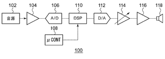
このような周波数補正をアナログ回路で実装すると、回路規模が膨大になる。そこで、デジタルのオーディオ信号に対して、デジタル信号処理を施すデジタル信号処理装置(DSP:Digital Signal Processor)が用いられる。図1は、DSPを備えるオーディオシステムのブロック図である。オーディオシステム100は、音源102、アナログアンプ104、A/Dコンバータ106、マイコン108、DSP110、D/Aコンバータ112、ボリューム回路114、パワーアンプ116、電気音響変換素子118を備える。
When such frequency correction is implemented by an analog circuit, the circuit scale becomes enormous. Therefore, a digital signal processor (DSP) that performs digital signal processing on a digital audio signal is used. FIG. 1 is a block diagram of an audio system including a DSP. The
音源102は、CDプレイヤ、DVDプレイヤ、シリコンオーディオプレイヤ、スマートホンなどであり、アナログオーディオ信号を出力する。アナログアンプ104は、音源102からのアナログオーディオ信号を増幅し、後段のA/Dコンバータ106の入力レンジにマッチさせる。あるいは音源102が生成するデジタルオーディオ信号は、DSP110に直接入力される。
The
DSP110は、A/Dコンバータ106もしくは音源102からのデジタルオーディオ信号を受け、所定のデジタル信号処理を施す。DSP110による信号処理としては、上述の周波数補正に関連する処理の他、ステレオ−モノラル変換、デジタルボリューム制御などが例示される。
The DSP 110 receives a digital audio signal from the A /
D/Aコンバータ112は、DSP110による処理を受けたデジタルオーディオ信号をアナログオーディオ信号に変換する。ボリューム回路114はD/Aコンバータ112の出力信号をボリューム値に応じた利得で増幅する。パワーアンプ116は、ボリューム回路114の出力を増幅し、電気音響変換素子118であるスピーカやヘッドホンを駆動する。
The D /
マイコン108は、オーディオシステム100を統合的に制御する。マイコン108は、ボリュームボタンやタッチパネルなどのユーザインタフェースを介して入力されるユーザの指令を受け、指令にもとづいてDSP110を制御する。マイコン108とDSP110は、バスあるいは制御ライン介して接続される。たとえばマイコン108は、ユーザによるボリューム変更の指示を検出すると、DSP110のデジタルボリューム回路のゲインの指令値をDSP110に送信する。
The
図2(a)、(b)は、DSP110の周波数補正に関連するブロック図である。図2(a)に示すようにDSP110は、マルチバンドイコライザ120と、マイコン108とのインタフェース回路130を備える。マルチバンドイコライザ120は、バンド数Mに対応する複数M個のフィルタ122_1〜122_Mを含む。マイコン108は、ユーザによるイコライザの変更の指示を検出すると、フィルタ122_1〜122_Mの設定データを送信する。
2A and 2B are block diagrams related to frequency correction of the
図2(b)は、フィルタ122の回路図である。このフィルタ122は、2次のIIR(Infinite Impulse Response)フィルタであり、5個の係数b0〜b2,a0,a1の組み合わせによって、Q値、周波数fおよびゲインが設定可能となっている。
FIG. 2B is a circuit diagram of the
インタフェース回路130は、たとえばI2C(Inter IC)シリアルインタフェースであり、8ビットを1ワードとしてデータ伝送が可能である。各係数が24ビット(あるいは32ビット)である場合、5個の係数を伝送するためには、1バンドあたり24×5/8=15回のデータ伝送が必要となり、M=13バンド分については、13×15=195回のデータ伝送が必要となる。
The
マイコン108とインタフェース回路130の間では、常時、さまざまなデータの送受信が行われている。一例として、オーディオシステム100は、再生中のオーディオ信号の周波数スペクトルを視覚的に表示する機能(スペクトラムアナライザ機能)を有し、オーディオ信号の再生中、マイコン108は、DSP110のインタフェース回路130を経由して、バンドごとの信号強度を読み出す。イコライザの設定変更のためのデータ伝送が割り込むと、そのたびにスペクトラムアナライザのためのデータ伝送が停止されるため、正しい周波数スペクトルが表示されなくなる。特にI2Cインタフェースでは、マスターからスレーブにデータを送信した後に、アクナリッジACKを待つ必要があり、オーバーヘッドが生じやすい。
Various data is constantly transmitted and received between the
本発明は係る課題に鑑みてなされたものであり、そのある態様の例示的な目的のひとつは、オーディオ再生中の、マイコンとDSP間のデータ伝送のデータ量/回数を削減することにある。 SUMMARY OF THE INVENTION The present invention has been made in view of the above problems, and one of exemplary purposes of an aspect thereof is to reduce the amount / number of data transmissions between a microcomputer and a DSP during audio playback.
本発明のある態様は、オーディオ用のデジタル信号処理装置に関する。デジタル信号処理装置は、外部のマイコンとの通信を行うインタフェース回路と、複数のバンドに対応する複数のデジタルフィルタを含み、各デジタルフィルタの周波数特性が係数群に応じて変更可能である、マルチバンドイコライザと、メモリと、複数のデジタルフィルタそれぞれの係数群を設定する係数設定回路と、を備える。マルチバンドイコライザの周波数特性は、複数のプリセットから選択可能である。(i)デジタル信号処理装置の起動時に、インタフェース回路は、マイコンから複数のプリセットに対応する複数の設定データを受信してメモリに格納する。(ii)オーディオ再生時において、インタフェース回路は、複数のプリセットのひとつを指定する選択データを受信する。また係数設定回路は、メモリに格納される複数の設定データのうち選択データに対応するひとつに応じて、複数のデジタルフィルタそれぞれの係数群を設定する。 One embodiment of the present invention relates to an audio digital signal processing apparatus. The digital signal processing device includes an interface circuit that communicates with an external microcomputer and a plurality of digital filters corresponding to a plurality of bands, and the frequency characteristics of each digital filter can be changed according to a coefficient group. An equalizer, a memory, and a coefficient setting circuit that sets coefficient groups of each of the plurality of digital filters are provided. The frequency characteristics of the multiband equalizer can be selected from a plurality of presets. (I) When the digital signal processing device is activated, the interface circuit receives a plurality of setting data corresponding to a plurality of presets from the microcomputer and stores them in the memory. (Ii) At the time of audio reproduction, the interface circuit receives selection data specifying one of a plurality of presets. The coefficient setting circuit sets a coefficient group for each of the plurality of digital filters according to one corresponding to the selected data among the plurality of setting data stored in the memory.
複数のプリセットに対応するすべての設定データは、システムの起動時に一括してマイコンからDSPへと送信され、オーディオ再生中には、選択データのみが送信される。これにより、オーディオ再生中のデータ伝送のデータ量、回数を減らすことができる。 All setting data corresponding to a plurality of presets is transmitted from the microcomputer to the DSP at the time of system startup, and only selected data is transmitted during audio reproduction. As a result, the amount and number of data transmissions during audio playback can be reduced.
設定データは、複数のデジタルフィルタそれぞれの係数群を含んでもよい。 The setting data may include a coefficient group for each of the plurality of digital filters.
複数のバンドそれぞれの周波数は固定されており、設定データは、複数のバンドそれぞれのゲインを含んでもよい。係数設定回路は、複数のバンドそれぞれについて、ゲインと、対応するデジタルフィルタの係数群の対応関係を保持してもよい。 The frequency of each of the plurality of bands is fixed, and the setting data may include the gain of each of the plurality of bands. The coefficient setting circuit may hold the correspondence between the gain and the corresponding digital filter coefficient group for each of the plurality of bands.
デジタル信号処理装置は、マルチバンドイコライザの前段もしくは後段に設けられ、オーディオ信号に、可変遅延を与える遅延回路をさらに備えてもよい。設定データは、複数のプリセットに対応する複数の遅延設定値を含んでもよい。オーディオ再生時において、係数設定回路は、メモリに格納される複数の設定データのうち選択データに対応するひとつに含まれる遅延設定値に応じて、遅延回路の遅延量を設定してもよい。
これにより、残響を利用したプリセットをサポートすることができる。
The digital signal processing apparatus may further include a delay circuit that is provided at the front stage or the rear stage of the multiband equalizer and gives a variable delay to the audio signal. The setting data may include a plurality of delay setting values corresponding to a plurality of presets. At the time of audio reproduction, the coefficient setting circuit may set the delay amount of the delay circuit according to the delay setting value included in one of the plurality of setting data stored in the memory corresponding to the selection data.
Thereby, a preset using reverberation can be supported.
デジタル信号処理装置は、ひとつの半導体基板上に一体集積化されてもよい。
「一体集積化」とは、回路の構成要素のすべてが半導体基板上に形成される場合や、回路の主要構成要素が一体集積化される場合が含まれ、回路定数の調節用に一部の抵抗やキャパシタなどが半導体基板の外部に設けられていてもよい。
The digital signal processing device may be integrated on a single semiconductor substrate.
“Integrated integration” includes the case where all of the circuit components are formed on a semiconductor substrate and the case where the main components of the circuit are integrated. A resistor, a capacitor, or the like may be provided outside the semiconductor substrate.
本発明の別の態様は、車載オーディオ装置に関する。車載オーディオ装置は、上述のいずれかのデジタル信号処理装置を備える。 Another aspect of this invention is related with a vehicle-mounted audio apparatus. The in-vehicle audio device includes any one of the digital signal processing devices described above.
本発明の別の態様は、電子機器に関する。電子機器は、上述のいずれかのデジタル信号処理装置を備える。 Another embodiment of the present invention relates to an electronic device. The electronic device includes any of the digital signal processing devices described above.
なお、以上の構成要素の任意の組み合わせや本発明の構成要素や表現を、方法、装置、システムなどの間で相互に置換したものもまた、本発明の態様として有効である。 Note that any combination of the above-described constituent elements and the constituent elements and expressions of the present invention replaced with each other among methods, apparatuses, systems, and the like are also effective as an aspect of the present invention.
本発明に係るオーディオ回路によれば、オーディオ再生中におけるマイコンとのデータ伝送のデータ量を削減できる。 According to the audio circuit of the present invention, the data amount of data transmission with the microcomputer during audio reproduction can be reduced.
以下、本発明を好適な実施の形態をもとに図面を参照しながら説明する。各図面に示される同一または同等の構成要素、部材、処理には、同一の符号を付するものとし、適宜重複した説明は省略する。また、実施の形態は、発明を限定するものではなく例示であって、実施の形態に記述されるすべての特徴やその組み合わせは、必ずしも発明の本質的なものであるとは限らない。 The present invention will be described below based on preferred embodiments with reference to the drawings. The same or equivalent components, members, and processes shown in the drawings are denoted by the same reference numerals, and repeated descriptions are omitted as appropriate. The embodiments do not limit the invention but are exemplifications, and all features and combinations thereof described in the embodiments are not necessarily essential to the invention.
本明細書において、「部材Aが、部材Bと接続された状態」とは、部材Aと部材Bが物理的に直接的に接続される場合のほか、部材Aと部材Bが、電気的な接続状態に影響を及ぼさない他の部材を介して間接的に接続される場合も含む。
同様に、「部材Cが、部材Aと部材Bの間に設けられた状態」とは、部材Aと部材C、あるいは部材Bと部材Cが直接的に接続される場合のほか、電気的な接続状態に影響を及ぼさない他の部材を介して間接的に接続される場合も含む。
In this specification, “the state in which the member A is connected to the member B” means that the member A and the member B are electrically connected in addition to the case where the member A and the member B are physically directly connected. It includes the case of being indirectly connected through another member that does not affect the connection state.
Similarly, “the state in which the member C is provided between the member A and the member B” refers to the case where the member A and the member C or the member B and the member C are directly connected, as well as an electrical condition. It includes the case of being indirectly connected through another member that does not affect the connection state.
(第1の実施の形態)
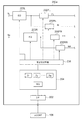
図3は、第2の実施の形態に係るDSP200のブロック図である。このDSP200は、デジタルオーディオ信号に対して、さまざまな信号処理を施す。たとえばDSP200は、図1のオーディオシステム100におけるDSP110として用いることができる。
(First embodiment)
FIG. 3 is a block diagram of a
DSP200は、マイコン108からの制御にもとづいて、オーディオ信号の周波数特性を変更可能となっている。DSP200は、インタフェース回路202、メモリ204、係数設定回路206、マルチバンドイコライザ220を備える。インタフェース回路202は、外部のマイコン108との通信を行う。たとえばインタフェース回路202は、I2Cインタフェースであってもよい。
The
マルチバンドイコライザ220は、複数M個(Mは2以上の整数)のバンドBAND1〜BANDMに対応する複数のデジタルフィルタ222_1〜222_Mを含み、各デジタルフィルタ222の周波数特性が、係数群に応じて変更可能である。デジタルフィルタ222は、IIR(Infinite Impulse Response)フィルタであってもよいし、FIR(Finite Impulse Response)フィルタであってもよい。加算器224は、複数M個のデジタルフィルタ222_1〜222_Mの出力を加算する。なお、マルチバンドイコライザ220の構成は図3のそれには限定されず、たとえば複数のデジタルフィルタ222は直列に接続されてもよい。あるいはマルチバンドイコライザ220を、複数のデジタルフィルタ222の直列接続と並列接続の組み合わせで構成してもよい。
The
係数設定回路206は、複数のデジタルフィルタ222_1〜222_Mそれぞれの係数群を設定する。たとえばデジタルフィルタ222が、図2(b)の2次IIRフィルタである場合、係数群は、5個の係数b0〜b2,a1,a2を含む。
The
マルチバンドイコライザ220の周波数特性は、複数N個(Nは2以上の整数)の周波数特性(以下、プリセットという)から選択可能である。たとえば、複数のプリセットは、フラット、ロック、ポップス、ボーカル、ピアノ、ジャズ、クラシックなど、オーディオのジャンルや楽器ごとに用意される。あるいは、複数のプリセットは、コンサートホールやジャズクラブ、教会などの残響を再現する音響調整機能のために用意されてもよい。またこれらのプリセットは、ルーム補正のためのイコライジングの成分を含んでもよい。
The frequency characteristics of the
DSP200の起動時に、インタフェース回路202は、複数のプリセットに対応する複数の設定データS1〜SNをマイコン108から受信し、それらをメモリ204に格納する。
When the
そしてオーディオ再生時において、インタフェース回路202は、複数のプリセットのひとつを指定する選択データSELを受信する。係数設定回路206は、メモリ204に格納される複数の設定データS1〜SNのうち選択データSELに対応するひとつに応じて、複数のデジタルフィルタ222_1〜222_Mそれぞれの係数群を設定する。
At the time of audio reproduction, the
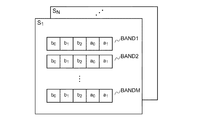
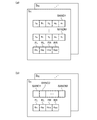
図4は、設定データの一例を示す図である。たとえば設定データS1は、複数のバンドBAND1〜BANDM(つまり複数のデジタルフィルタ222)に対応する、複数の係数群を含んでいる。その他の設定データS2〜SNも同様である。 FIG. 4 is a diagram illustrating an example of setting data. For example setting data S 1 corresponds to a plurality of bands BAND1~BANDM (i.e. a plurality of digital filter 222) includes a plurality of coefficient groups. The same applies to the other setting data S 2 to S N.
オーディオ再生中に、i番目(1≦i≦N)のプリセットを指示する選択信号SELがメモリ204に書き込まれたとする。このとき、係数設定回路206は、i番目の設定データSiを参照し、それに含まれる各バンドの係数群を、対応するバンドのデジタルフィルタ222に設定する。
It is assumed that a selection signal SEL for instructing an i-th (1 ≦ i ≦ N) preset is written in the
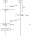
以上がDSP200の構成である。続いてその動作を説明する。図5は、DSP200を備えるオーディオシステム100のシーケンス図である。起動直後に、セットアップシーケンスS100が実行される。セットアップシーケンスS100では、複数N個のプリセットに対応するN個の設定データS1〜SNが、マイコン108からDSP200に送信される(S102)。この送信は、割り込み処理ではなく、予定された処理である。DSP200のインタフェース回路202は、受信したN個の設定データS1〜SNをメモリ204に格納する。
The above is the configuration of the
マイコン108は、セットアップシーケンスの完了後、再生シーケンスに移行する前に、複数のデジタルフィルタ222の係数群が初期化される。たとえば、DSP200は、プリセットの初期値(デフォルト値)を保持しており、その初期値に応じてマルチバンドイコライザ220を初期化してもよい。あるいはセットアップシーケンス中にDSP200が、プリセットの初期値を、選択データSELとしてDSP200に送信してもよい。
The
セットアップシーケンスS100が完了すると、再生シーケンスS110に移行する。再生シーケンス中、DSP200は、オーディオ信号に対して、図5のシーケンス図に示されない様々な信号処理を施している。またマイコン108は、再生シーケンス中に、DSP200との間でシーケンス図に示されない様々なデータの送受信を行っている。たとえばこの送受信には、スペクトラムアナライザ機能のためのデータ伝送が含まれる。
When the setup sequence S100 is completed, the process proceeds to the reproduction sequence S110. During the playback sequence, the
マイコン108は、再生シーケンスS110の間に、ユーザによるプリセットの変更の入力を検出すると(S112)、変更後のプリセットを指定する選択データSELをDSP200に送信する(S114)。
When the
DSP200の係数設定回路206は、選択データSELが指定するプリセットに対応する設定データSiを選択し(S116)、選択した設定データSiに対応する係数群を、デジタルフィルタ222にセットする(S118)。その後、再びイコライザの変更が指示されると、S112〜S118の処理が行われる。
以上がDSP200を備えるオーディオシステム100の動作である。このDSP200によれば、セットアップシーケンスの間に、すべてのプリセットに対応する設定データS1〜SNを送信しておき、オーディオ再生中には、プリセットを指定する選択データSELのみを送信することとした。たとえばN=8個のプリセットが選択可能である場合、選択データSELは3ビットでよく、したがってオーディオ再生中にプリセットイコライザの変更があった場合に、1回のデータ伝送のみで、プリセットを切りかえることができる。
The above is the operation of the
これと引き替えに、セットアップシーケンスS100において、すべてのプリセットに対応する設定データS1〜SNが送信される。図4に示すように、各設定データSが、バンドごとの係数群を含むとする。係数群が5個の係数を含み、各係数が24ビットであり、M=13バンドのシステムにおいては、セットアップシーケンスS100において
5×24ビット×M×N=5×24×13×8=12480ビット
のデータを送信することとなる。1ワード8ビットのシリアルインタフェースでは、1560回のデータ伝送が発生する。ただし、セットアップシーケンスS100のデータ伝送は、割り込み処理ではなく、予定されたものである。したがって、その他のデータ伝送の邪魔になることはなく、DSP200やマイコン108の処理のボトルネックとなることもない。また、割り込み処理を考慮しなくて済むため、ソフトウェアの設計の負担が大幅に軽減される。
In exchange for this, in the setup sequence S100, the setting data S 1 to S N corresponding to all the presets are transmitted. As shown in FIG. 4, it is assumed that each setting data S includes a coefficient group for each band. The coefficient group includes 5 coefficients, each coefficient is 24 bits, and in an M = 13 band system, 5 × 24 bits × M × N = 5 × 24 × 13 × 8 = 1240 bits in the setup sequence S100 Will be transmitted. In a 1-word 8-bit serial interface, data transmission occurs 1560 times. However, the data transmission of the setup sequence S100 is not an interrupt process but a scheduled one. Therefore, it does not interfere with other data transmission, and does not become a bottleneck in processing of the
(第2の実施の形態)
第1の実施の形態では、マルチバンドイコライザ220において複数のバンドBAND1〜BANDMの周波数が可変であった。このようなイコライザをパラメトリックイコライザとも称する。第2の実施の形態では、各バンドの周波数が固定されている。このようなイコライザは、グラフィックイコライザとも称される。たとえば複数のバンドの周波数は、オクターブ刻みで規定される。そしてマルチバンドイコライザ220は、各バンドのゲインのみが可変となっている。図6(a)は、設定データの別の一例を示す図である。図6(a)の設定データS1は、複数のバンドBAND1〜BANDMそれぞれのゲインg1〜gMを含む。その他の設定データS2〜SNも同様である。
(Second Embodiment)
In the first embodiment, in the
係数設定回路206は、複数のバンドBAND1〜BANDMそれぞれについて、ゲインgと、対応するデジタルフィルタ222の係数群の対応関係を保持する。図6(b)は、第1バンドBAND1の、ゲインgと係数群の対応関係を示すテーブルである。たとえばゲインgの値は、−7dB〜+7dBの間で、1dB刻みで15段階から選択可能である。ゲインの値ごとに、係数群b0〜b2,a0,a1が保持されている。なお係数の具体的な値は省略されている。その他のバンドBAND2〜BANDMについても同様である。図6(b)の対応関係は、テーブルとして保持されてもよいし、演算式で保持してもよい。
The
各バンドのゲインが15段階で設定可能である場合、ゲインの設定は4ビットとなる。第2の実施の形態によれば、セットアップシーケンスS100において伝送される設定データS1〜SNは、
4ビット×M×N=4×13×8=416ビット
となり、1ワード8ビットのシリアルインタフェースを用いた場合、52回のデータ伝送で足り、第1の実施の形態に比べて大幅に削減される。
When the gain of each band can be set in 15 steps, the gain setting is 4 bits. According to the second embodiment, the setting data S 1 to S N transmitted in the setup sequence S100 are:
4 bits x M x N = 4 x 13 x 8 = 416 bits. When a 1-word 8-bit serial interface is used, 52 times of data transmission is sufficient, which is a significant reduction compared to the first embodiment. The
第2の実施の形態は、バンド数Mが10以上と大きい用途に適していると言え、反対に第1の実施の形態は、バンド数Mが10以下、より好ましくは5以下の用途に適していると言える。 The second embodiment can be said to be suitable for applications where the number of bands M is as large as 10 or more. On the other hand, the first embodiment is suitable for applications where the number of bands M is 10 or less, more preferably 5 or less. It can be said that.
(第3の実施の形態)
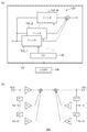
図7は、第3の実施の形態に係るDSP200aのブロック図である。DSP200aは、たとえば2チャンネル(Lチャンネル、Rチャンネル)で構成され、チャンネルごとにマルチバンドイコライザ220L,220Rを備える。ここでは車載オーディオ用のDSPを例に説明する。車載オーディオシステムは、フロント左右、リア左右、合計4個のスピーカを備える。マルチバンドイコライザ220Lの出力は、左側の前後のスピーカに振り分けられ、マルチバンドイコライザ220Rの出力は、右側の前後のスピーカに振り分けられる。
(Third embodiment)
FIG. 7 is a block diagram of a
DSP200aはさらに、遅延回路230FL,230RL,230FR,230RRを備える。これらの遅延回路230は可変遅延回路であり、遅延量が遅延設定値に応じて独立に調節可能となっている。
The
なお図7では明確化のため、Lチャンネル、Rチャンネルそれぞれにおいて、フロントとリアでひとつのマルチバンドイコライザ220を共有しているが本発明はそれには限定されない。すなわち、フロントとリアそれぞれに個別にマルチバンドイコライザ220を設けてもよく、したがってマルチバンドイコライザ220は、スピーカごとに設けられてもよい。これにより、より臨場感のあふれる音場の設定が可能となる。あるいは、マルチバンドイコライザは、全チャンネルで共通の1個のみを設けてもよい。あるいは、フロントLチャンネル、フロントRチャンネルで共有される1個のマルチバンドイコライザ220と、リアLチャンネル、リアRチャンネルで共有される1個のマルチバンドイコライザ220と、を設けてもよい。
In FIG. 7, for the sake of clarity, one
図8(a)、(b)は、設定データの一例を示す図である。設定データS1は、マルチバンドイコライザ220のためのデータに加えて、複数の遅延回路230FL,230RL,230FR,230RRのための遅延設定値DFL,DRL,DFR,DRRを含む。図8(a)の設定データS1は、マルチバンドイコライザ220ためのデータを、図4のフォーマットで含む。図8(b)の設定データS1は、マルチバンドイコライザ220ためのデータを、図6(a)のフォーマットで含む。なお図7において、同じプリセットに対して、マルチバンドイコライザ220Lとマルチバンドイコライザ220Rに異なる周波数特性を設定する場合、設定データS1に、Lチャンネルのマルチバンドイコライザ220Lのためのデータと、Rチャンネルのマルチバンドイコライザ220Rのためのデータを含めればよい。
FIGS. 8A and 8B are diagrams illustrating an example of setting data. The setting data S 1 includes delay setting values D FL , D RL , D FR , D RR for the plurality of delay circuits 230 FL, 230 RL, 230 FR, 230 RR in addition to the data for the
続いてDSP200aの動作を説明する。インタフェース回路202は、セットアップシーケンスにおいて、複数のプリセットに対応する複数の設定データS1〜SNを受信し、メモリ204に保持する。インタフェース回路202がプリセットを指定する選択データSELを受信すると、係数設定回路206は、選択データSELに応じたひとつの設定データSiを選択し、それにもとづいてマルチバンドイコライザ220L,220Rの周波数特性ならびに遅延回路230FL,230RL,230FR,230RRの遅延量を設定する。
Next, the operation of the
以上が第3の実施の形態に係るDSP200aの構成および動作である。このDSP200aによれば、遅延を利用したプリセットを、瞬時に切りかえることができる。たとえば音響調整機能に関するプリセットは、リアスピーカからの音を、フロントスピーカからの音に対して遅延させることによる残響効果を利用することがある。第3の実施の形態によれば、プリセットごとに遅延量を切りかえることができるため、音響調整用などに関するプリセットをサポートすることができる。
The above is the configuration and operation of the
あるいは、カーオーディオでは、視聴位置(たとえば運転席)と、4個のスピーカの距離がそれぞれ異なっており、同じ位相でスピーカが鳴ると、視聴位置において位相がずれて音像がぼやけることとなる。これを補正するためのルーム補正(音場補正、固定イライザともいう)においては、スピーカごとに異なる遅延量を設定する必要がある。第3の実施の形態によれば、ルーム補正を考慮したプリセットを選択することができる。 Alternatively, in the car audio, the viewing position (for example, the driver's seat) and the distance between the four speakers are different from each other. If the speakers sound at the same phase, the sound image blurs due to a phase shift at the viewing position. In room correction (also referred to as sound field correction or fixed equalizer) for correcting this, it is necessary to set a different delay amount for each speaker. According to the third embodiment, a preset considering room correction can be selected.
(用途)
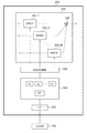
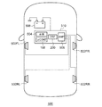
最後に、DSP200の用途を説明する。図9は、DSP200を用いた車載オーディオ装置500の構成を示すブロック図である。車載オーディオ装置500は、4チャンネル(フロント右FR、リア右RR、フロント左FL、リア左RL)で構成され、4チャンネルに対応する複数のスピーカ502FR,502RR,502FL,502RLを備える。車載オーディオ装置500は、さらにセンターチャンネル、サブウーファチャンネルを備える5.1チャンネルであってもよい。
(Use)
Finally, the use of the
音源504は、CDプレイヤ、DVDプレイヤ、ブルーレイプレイヤ、HDD/シリコンオーディオプレイヤ、ラジオチューナなどであり、アナログあるいはデジタルのオーディオ信号を再生する。DSP200は、音源504からのオーディオ信号を受け、さまざまなデジタル信号処理を施す。DSP200の処理を受けたオーディオ信号は、アナログオーディオ信号に変換され、アンプ506に入力される。アンプ506は、各チャンネルのアナログオーディオ信号を増幅し、対応するスピーカ502を駆動する。マイコン108は、DSP200をはじめとするブロックを統合的に制御する。音源504、マイコン108、DSP200、アンプ506は、バッテリ508からの給電を受けて動作する。音源504、マイコン108、DSP200、アンプ506は、ヘッドユニット510に内蔵されてもよい。なおアンプ506は、DSP200と同一のチップに集積化されてもよい。
The
ユーザ(運転者)がイグニッションをオン(あるいはアクセサリオン)すると、マイコン108をはじめとする回路に電源が供給される。電源が供給されると、セットアップシーケンスに移行し、マイコン108からDSP200に対して、設定データS1〜SNが送信される。
When the user (driver) turns on the ignition (or accessories on), power is supplied to circuits including the
DSP200は、車載オーディオ装置の他、オーディオコンポーネント装置、テレビ、デスクトップPC、ノートPC、タブレットPC、携帯電話端末、デジタルカメラ、ポータブルオーディオプレイヤなどの電子機器に搭載することもできる。
The
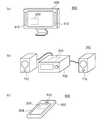
図10(a)〜(c)は、電子機器の外観図である。図10(a)は電子機器の一例であるディスプレイ装置600である。ディスプレイ装置600は、筐体602、スピーカ612を備える。DSP200は筐体に内蔵される。
10A to 10C are external views of electronic devices. FIG. 10A illustrates a
図10(b)は電子機器の一例であるオーディオコンポーネント装置700である。オーディオコンポーネント装置700は、筐体702、スピーカ712を備える。DSP200は筐体702に内蔵される。
FIG. 10B shows an
図10(c)は電子機器の一例である小型情報端末800である。小型情報端末800は、携帯電話、タブレット端末、オーディオプレイヤなどである。小型情報端末800は、筐体802、スピーカ812、ディスプレイ804を備える。DSP200は筐体802に内蔵される。
FIG. 10C illustrates a
実施の形態にもとづき、具体的な語句を用いて本発明を説明したが、実施の形態は、本発明の原理、応用を示しているにすぎず、実施の形態には、請求の範囲に規定された本発明の思想を逸脱しない範囲において、多くの変形例や配置の変更が認められる。 Although the present invention has been described using specific terms based on the embodiments, the embodiments only illustrate the principles and applications of the present invention, and the embodiments are defined in the claims. Many variations and modifications of the arrangement are permitted without departing from the spirit of the present invention.
100…オーディオシステム、102…音源、104…アナログアンプ、106…A/Dコンバータ、108…マイコン、110…DSP、112…D/Aコンバータ、114…ボリューム回路、116…パワーアンプ、118…電気音響変換素子、120…マルチバンドイコライザ、122…フィルタ、130…インタフェース回路、200…DSP、202…インタフェース回路、204…メモリ、206…係数設定回路、220…マルチバンドイコライザ、222…デジタルフィルタ、230…遅延回路。
DESCRIPTION OF
Claims (7)
外部のマイコンとの通信を行うインタフェース回路と、
複数のバンドに対応する複数のデジタルフィルタを含み、各デジタルフィルタの周波数特性が係数群に応じて変更可能である、マルチバンドイコライザと、
メモリと、
前記複数のデジタルフィルタそれぞれの前記係数群を設定する係数設定回路と、
を備え、
前記マルチバンドイコライザの周波数特性は、複数のプリセットから選択可能であり、
(i)前記デジタル信号処理装置の起動時に、前記インタフェース回路は、前記マイコンから前記複数のプリセットに対応する複数の設定データを受信して前記メモリに格納し、
(ii)オーディオ再生時において、前記インタフェース回路は、前記複数のプリセットのひとつを指定する選択データを受信し、前記係数設定回路は、前記メモリに格納される複数の設定データのうち前記選択データに対応するひとつに応じて、前記複数のデジタルフィルタそれぞれの前記係数群を設定することを特徴とするデジタル信号処理装置。 A digital signal processing device for audio,
An interface circuit for communicating with an external microcomputer;
A multi-band equalizer including a plurality of digital filters corresponding to a plurality of bands, the frequency characteristics of each digital filter being changeable according to a coefficient group;
Memory,
A coefficient setting circuit for setting the coefficient group of each of the plurality of digital filters;
With
The frequency characteristics of the multiband equalizer can be selected from a plurality of presets,
(I) Upon activation of the digital signal processing device, the interface circuit receives a plurality of setting data corresponding to the plurality of presets from the microcomputer and stores them in the memory;
(Ii) At the time of audio reproduction, the interface circuit receives selection data specifying one of the plurality of presets, and the coefficient setting circuit uses the selection data among the plurality of setting data stored in the memory. The digital signal processing apparatus, wherein the coefficient group of each of the plurality of digital filters is set according to a corresponding one.
前記設定データは、前記複数のバンドそれぞれのゲインを含み、
前記係数設定回路は、前記複数のバンドそれぞれについて、前記ゲインと、前記対応する前記デジタルフィルタの係数群の対応関係を保持することを特徴とする請求項1に記載のデジタル信号処理装置。 The frequency of each of the plurality of bands is fixed,
The setting data includes gains of the plurality of bands,
The digital signal processing apparatus according to claim 1, wherein the coefficient setting circuit holds a correspondence relationship between the gain and the corresponding coefficient group of the digital filter for each of the plurality of bands.
前記設定データは、前記複数のプリセットに対応する複数の遅延設定値を含み、
オーディオ再生時において、前記係数設定回路は、前記メモリに格納される複数の設定データのうち前記選択データに対応するひとつに含まれる前記遅延設定値に応じて、前記遅延回路の遅延量を設定することを特徴とする請求項1から3のいずれかに記載のデジタル信号処理装置。 A delay circuit that is provided in a preceding stage or a subsequent stage of the multiband equalizer, and that gives a variable delay to the audio signal;
The setting data includes a plurality of delay setting values corresponding to the plurality of presets,
At the time of audio reproduction, the coefficient setting circuit sets the delay amount of the delay circuit according to the delay setting value included in one of the plurality of setting data stored in the memory corresponding to the selection data. The digital signal processing apparatus according to claim 1, wherein the digital signal processing apparatus is a digital signal processing apparatus.
Priority Applications (2)
| Application Number | Priority Date | Filing Date | Title |
|---|---|---|---|
| JP2016003685A JP6737597B2 (en) | 2016-01-12 | 2016-01-12 | Audio digital signal processing device and vehicle-mounted audio device and electronic equipment using the same |
| US15/401,424 US10506340B2 (en) | 2016-01-12 | 2017-01-09 | Digital signal processor for audio, in-vehicle audio system and electronic apparatus including the same |
Applications Claiming Priority (1)
| Application Number | Priority Date | Filing Date | Title |
|---|---|---|---|
| JP2016003685A JP6737597B2 (en) | 2016-01-12 | 2016-01-12 | Audio digital signal processing device and vehicle-mounted audio device and electronic equipment using the same |
Publications (2)
| Publication Number | Publication Date |
|---|---|
| JP2017126830A true JP2017126830A (en) | 2017-07-20 |
| JP6737597B2 JP6737597B2 (en) | 2020-08-12 |
Family
ID=59275248
Family Applications (1)
| Application Number | Title | Priority Date | Filing Date |
|---|---|---|---|
| JP2016003685A Active JP6737597B2 (en) | 2016-01-12 | 2016-01-12 | Audio digital signal processing device and vehicle-mounted audio device and electronic equipment using the same |
Country Status (2)
| Country | Link |
|---|---|
| US (1) | US10506340B2 (en) |
| JP (1) | JP6737597B2 (en) |
Families Citing this family (3)
| Publication number | Priority date | Publication date | Assignee | Title |
|---|---|---|---|---|
| US10491997B2 (en) * | 2017-04-27 | 2019-11-26 | Cirrus Logic, Inc. | Controlling noise transfer function of signal path to reduce charge pump noise |
| TWI683534B (en) * | 2019-09-19 | 2020-01-21 | 宏碁股份有限公司 | Adjusting system and adjusting method thereof for equalization processing |
| EP4373134A4 (en) * | 2021-07-15 | 2024-11-13 | Sony Group Corporation | INFORMATION PROCESSING DEVICE, INFORMATION PROCESSING METHOD AND PROGRAM |
Citations (7)
| Publication number | Priority date | Publication date | Assignee | Title |
|---|---|---|---|---|
| JPH02250420A (en) * | 1989-03-24 | 1990-10-08 | Fujitsu Ten Ltd | Filter coefficient revision system for digital filter |
| JPH08250978A (en) * | 1995-03-07 | 1996-09-27 | Mitsubishi Electric Corp | Audio filter device |
| JPH11331995A (en) * | 1998-05-08 | 1999-11-30 | Alpine Electronics Inc | Sound image controller |
| US20090015594A1 (en) * | 2005-03-18 | 2009-01-15 | Teruo Baba | Audio signal processing device and computer program for the same |
| JP2009147629A (en) * | 2007-12-13 | 2009-07-02 | Mitsubishi Electric Corp | Sound equipment |
| JP2010233198A (en) * | 2009-03-05 | 2010-10-14 | Rohm Co Ltd | Audio signal processing circuit, filter circuit, and audio system using the filter circuit |
| JP2015201729A (en) * | 2014-04-07 | 2015-11-12 | ローム株式会社 | Mixer circuit, audio signal processing circuit, audio signal mixing method, on-vehicle audio device using the method, audio component device, and electronic apparatus |
Family Cites Families (7)
| Publication number | Priority date | Publication date | Assignee | Title |
|---|---|---|---|---|
| US5892833A (en) * | 1993-04-28 | 1999-04-06 | Night Technologies International | Gain and equalization system and method |
| JP3235925B2 (en) * | 1993-11-19 | 2001-12-04 | 松下電器産業株式会社 | Howling suppression device |
| US8724822B2 (en) * | 2003-05-09 | 2014-05-13 | Nuance Communications, Inc. | Noisy environment communication enhancement system |
| CN101053152B (en) * | 2005-07-29 | 2010-12-29 | 哈曼国际工业有限公司 | automatic audio tuning system and method |
| JP2007096694A (en) * | 2005-09-28 | 2007-04-12 | Neuro Solution Corp | Fm transmitter |
| WO2008124786A2 (en) * | 2007-04-09 | 2008-10-16 | Personics Holdings Inc. | Always on headwear recording system |
| US9280964B2 (en) * | 2013-03-14 | 2016-03-08 | Fishman Transducers, Inc. | Device and method for processing signals associated with sound |
-
2016
- 2016-01-12 JP JP2016003685A patent/JP6737597B2/en active Active
-
2017
- 2017-01-09 US US15/401,424 patent/US10506340B2/en active Active
Patent Citations (7)
| Publication number | Priority date | Publication date | Assignee | Title |
|---|---|---|---|---|
| JPH02250420A (en) * | 1989-03-24 | 1990-10-08 | Fujitsu Ten Ltd | Filter coefficient revision system for digital filter |
| JPH08250978A (en) * | 1995-03-07 | 1996-09-27 | Mitsubishi Electric Corp | Audio filter device |
| JPH11331995A (en) * | 1998-05-08 | 1999-11-30 | Alpine Electronics Inc | Sound image controller |
| US20090015594A1 (en) * | 2005-03-18 | 2009-01-15 | Teruo Baba | Audio signal processing device and computer program for the same |
| JP2009147629A (en) * | 2007-12-13 | 2009-07-02 | Mitsubishi Electric Corp | Sound equipment |
| JP2010233198A (en) * | 2009-03-05 | 2010-10-14 | Rohm Co Ltd | Audio signal processing circuit, filter circuit, and audio system using the filter circuit |
| JP2015201729A (en) * | 2014-04-07 | 2015-11-12 | ローム株式会社 | Mixer circuit, audio signal processing circuit, audio signal mixing method, on-vehicle audio device using the method, audio component device, and electronic apparatus |
Also Published As
| Publication number | Publication date |
|---|---|
| JP6737597B2 (en) | 2020-08-12 |
| US20170201828A1 (en) | 2017-07-13 |
| US10506340B2 (en) | 2019-12-10 |
Similar Documents
| Publication | Publication Date | Title |
|---|---|---|
| CN103888103B (en) | system and method for digital signal processing | |
| CN104285451B (en) | Audio system | |
| US20110116642A1 (en) | Audio System with Portable Audio Enhancement Device | |
| US8396233B2 (en) | Beam forming in spatialized audio sound systems using distributed array filters | |
| CN103886866A (en) | System And Method For Digital Signal Processing | |
| JP2015167413A (en) | Spectrum management system | |
| CN106713794B (en) | A method for adjusting audio balance and an audio system providing balance adjustment | |
| JP6737597B2 (en) | Audio digital signal processing device and vehicle-mounted audio device and electronic equipment using the same | |
| JP6402666B2 (en) | Information processing apparatus and information processing method therefor | |
| CN111510847B (en) | Micro loudspeaker array, in-vehicle sound field control method and device and storage device | |
| US20190131947A1 (en) | Audio circuit | |
| US11314477B2 (en) | Audio processing apparatus, operation method of audio processing apparatus, and audio processing system | |
| US9949026B2 (en) | Audio monitor signal interception device | |
| JPWO2007004433A1 (en) | Sound image localization controller | |
| JP4840641B2 (en) | Audio signal delay time difference automatic correction device | |
| JP6474246B2 (en) | Audio signal processing circuit, in-vehicle audio device, audio component device, electronic equipment | |
| US20180192188A1 (en) | Input of time delay values to signal processor | |
| JP2002101499A (en) | Sound reproduction device | |
| CN213880236U (en) | Sound effect conversion device | |
| JP6185363B2 (en) | SOUND SYSTEM, SOUND DEVICE, AND SOUND QUALITY ADJUSTING METHOD | |
| JP4940634B2 (en) | Audio system | |
| HK1197312B (en) | System and method for digital signal processing | |
| HK1197323B (en) | System and method for digital signal processing | |
| HK1197323A1 (en) | System and method for digital signal processing | |
| GB2447634A (en) | Sound output device with earphone mode and speaker mode |
Legal Events
| Date | Code | Title | Description |
|---|---|---|---|
| A621 | Written request for application examination |
Free format text: JAPANESE INTERMEDIATE CODE: A621 Effective date: 20181206 |
|
| A977 | Report on retrieval |
Free format text: JAPANESE INTERMEDIATE CODE: A971007 Effective date: 20190819 |
|
| A131 | Notification of reasons for refusal |
Free format text: JAPANESE INTERMEDIATE CODE: A131 Effective date: 20190827 |
|
| A521 | Request for written amendment filed |
Free format text: JAPANESE INTERMEDIATE CODE: A523 Effective date: 20191024 |
|
| A131 | Notification of reasons for refusal |
Free format text: JAPANESE INTERMEDIATE CODE: A131 Effective date: 20200128 |
|
| A521 | Request for written amendment filed |
Free format text: JAPANESE INTERMEDIATE CODE: A523 Effective date: 20200325 |
|
| TRDD | Decision of grant or rejection written | ||
| A01 | Written decision to grant a patent or to grant a registration (utility model) |
Free format text: JAPANESE INTERMEDIATE CODE: A01 Effective date: 20200707 |
|
| A61 | First payment of annual fees (during grant procedure) |
Free format text: JAPANESE INTERMEDIATE CODE: A61 Effective date: 20200716 |
|
| R150 | Certificate of patent or registration of utility model |
Ref document number: 6737597 Country of ref document: JP Free format text: JAPANESE INTERMEDIATE CODE: R150 |
|
| R250 | Receipt of annual fees |
Free format text: JAPANESE INTERMEDIATE CODE: R250 |
|
| R250 | Receipt of annual fees |
Free format text: JAPANESE INTERMEDIATE CODE: R250 |
|
| R250 | Receipt of annual fees |
Free format text: JAPANESE INTERMEDIATE CODE: R250 |