JP2017128754A - Can roll and vacuum film deposition apparatus, and film deposition method for long-sized body - Google Patents
Can roll and vacuum film deposition apparatus, and film deposition method for long-sized body Download PDFInfo
- Publication number
- JP2017128754A JP2017128754A JP2016007764A JP2016007764A JP2017128754A JP 2017128754 A JP2017128754 A JP 2017128754A JP 2016007764 A JP2016007764 A JP 2016007764A JP 2016007764 A JP2016007764 A JP 2016007764A JP 2017128754 A JP2017128754 A JP 2017128754A
- Authority
- JP
- Japan
- Prior art keywords
- roll
- film
- outer peripheral
- peripheral surface
- resin film
- Prior art date
- Legal status (The legal status is an assumption and is not a legal conclusion. Google has not performed a legal analysis and makes no representation as to the accuracy of the status listed.)
- Granted
Links
Images



Landscapes
- Physical Vapour Deposition (AREA)
Abstract
Description
本発明は、ロールツーロールで搬送される長尺体(長尺状耐熱性樹脂フィルム、金属箔、金属ストリップ等)をキャンロール外周面に巻き付けながらスパッタリング等の成膜を行う真空成膜装置に係り、特に、成膜時に発生し易い長尺体の皺を抑制できるキャンロールと真空成膜装置および長尺体の成膜方法に関するものである。 The present invention provides a vacuum film forming apparatus that performs film formation such as sputtering while winding a long body (long heat-resistant resin film, metal foil, metal strip, etc.) conveyed by roll-to-roll around the outer surface of a can roll. In particular, the present invention relates to a can roll, a vacuum film forming apparatus, and a method for forming a long body that can suppress wrinkles of the long body that are likely to occur during film formation.
液晶パネル、ノートパソコン、デジタルカメラ、携帯電話等には、フレキシブル配線基板が用いられている。フレキシブル配線基板は、耐熱性樹脂フィルムの片面若しくは両面に金属膜を成膜した金属膜付耐熱性樹脂フィルムから作製される。近年、フレキシブル配線基板に形成される配線パターンはますます微細化、高密度化しており、金属膜付耐熱性樹脂フィルム自体が皺のない平滑なものであることがより一層重要になってきている。 Flexible wiring boards are used in liquid crystal panels, notebook computers, digital cameras, mobile phones, and the like. The flexible wiring board is manufactured from a heat-resistant resin film with a metal film in which a metal film is formed on one side or both sides of a heat-resistant resin film. In recent years, wiring patterns formed on flexible wiring boards have become increasingly finer and denser, and it has become even more important that the heat-resistant resin film with metal film itself is smooth and free from defects. .
この種の金属膜付耐熱性樹脂フィルムの製造方法としては、接着剤により金属箔を耐熱性樹脂フィルムに貼り付けて製造する方法(3層基板の製造方法と称される)、金属箔に耐熱性樹脂溶液をコーティングした後、乾燥させて製造する方法(キャスティング法と称される)、乾式めっき法(真空成膜法)若しくは乾式めっき法(真空成膜法)と湿式めっき法との組み合わせにより耐熱性樹脂フィルムに金属膜を成膜して製造する方法(メタライジング法と称される)等が従来から知られている。また、メタライジング法における上記乾式めっき法(真空成膜法)には、真空蒸着法、スパッタリング法、イオンプレーティング法、イオンビームスパッタリング法等がある。 As a manufacturing method of this kind of heat-resistant resin film with a metal film, a method of manufacturing by attaching a metal foil to a heat-resistant resin film with an adhesive (referred to as a manufacturing method of a three-layer substrate), heat-resistant to the metal foil By coating with a conductive resin solution and drying to manufacture (called casting method), dry plating method (vacuum film forming method) or a combination of dry plating method (vacuum film forming method) and wet plating method A method for producing a metal film on a heat-resistant resin film (referred to as a metallizing method) has been conventionally known. Further, the dry plating method (vacuum film forming method) in the metalizing method includes a vacuum deposition method, a sputtering method, an ion plating method, an ion beam sputtering method and the like.
上記メタライジング法については、特許文献1に、ポリイミド絶縁層上にクロムをスパッタリングした後、銅をスパッタリングしてポリイミド絶縁層上に導体層を形成する方法が開示されている。また、特許文献2に、銅ニッケル合金をターゲットとするスパッタリングで形成した第一の金属薄膜と、銅をターゲットとするスパッタリングで形成した第二の金属薄膜とが、この順でポリイミドフィルム上に積層されたフレキシブル回路基板用材料(すなわち、銅張積層樹脂フィルム基板)が開示されている。尚、ポリイミドフィルム等の耐熱性樹脂フィルムに真空成膜を行って金属膜付耐熱性樹脂フィルムを製造する場合、以下に述べるスパッタリングウェブコータを用いることが一般的である。 Regarding the metallizing method, Patent Document 1 discloses a method in which chromium is sputtered on a polyimide insulating layer and then copper is sputtered to form a conductor layer on the polyimide insulating layer. In Patent Document 2, a first metal thin film formed by sputtering using a copper nickel alloy as a target and a second metal thin film formed by sputtering using copper as a target are laminated on a polyimide film in this order. A flexible circuit board material (that is, a copper-clad laminated resin film substrate) is disclosed. In addition, when manufacturing a heat resistant resin film with a metal film by vacuum film-forming on heat resistant resin films, such as a polyimide film, it is common to use the sputtering web coater described below.
上記スパッタリング法は、一般に、成膜された金属薄膜等の密着力に優れる利点を有する反面、真空蒸着法に較べて耐熱性樹脂フィルムに与える熱負荷が大きいといわれている。そして、成膜の際に耐熱性樹脂フィルムに大きな熱負荷がかかるとフィルムに皺が発生し易くなることも知られている。 In general, the sputtering method has an advantage of excellent adhesion of a formed metal thin film or the like, but it is said that the thermal load applied to the heat resistant resin film is larger than that of the vacuum deposition method. It is also known that wrinkles are likely to occur in the film when a large heat load is applied to the heat resistant resin film during film formation.
皺の発生を防ぐため、スパッタリングウェブコータでは、ロールツーロールにより搬送される長尺状耐熱性樹脂フィルムを、冷却機能を有するキャンロール外周面に巻き付けることで成膜中の耐熱性樹脂フィルムを裏面側から冷却する方式が採用されている。例えば、特許文献3には、スパッタリングウェブコータの一例である巻出巻取式(ロールツーロール方式)の真空スパッタリング装置が開示されている。この巻出巻取式の真空スパッタリング装置には、キャンロールとして機能するクーリングロールを具備し、更に、クーリングロールの少なくとも耐熱性樹脂フィルムの搬入側(搬送上流側)にサブロール(前フィードロール)が設けられており、このサブロールによって耐熱性樹脂フィルムをクーリングロールに密着させる制御が行われている。 In order to prevent wrinkling, the sputtering web coater has a long heat-resistant resin film conveyed by roll-to-roll wound around the outer peripheral surface of the can roll having a cooling function so that the heat-resistant resin film being formed is backside. The method of cooling from the side is adopted. For example, Patent Literature 3 discloses an unwinding type (roll-to-roll type) vacuum sputtering apparatus which is an example of a sputtering web coater. This unwinding / winding-type vacuum sputtering apparatus includes a cooling roll that functions as a can roll, and a sub-roll (pre-feed roll) is provided at least on the carry-in side (upstream side of the heat-resistant resin film) of the cooling roll. The sub-roll is used to control the heat-resistant resin film in close contact with the cooling roll.
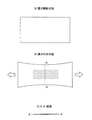
ところで、熱負荷が作用していない長尺状耐熱性樹脂フィルムに対し長さ方向へ向けて張力が印加された場合でも、図1(A)〜(C)に示すように樹脂フィルムの中央部に皺が発生する。すなわち、図1(A)に示すように樹脂フィルムに対し長さ方向への張力が印加されていない場合(張力開放状態)には樹脂フィルムに弛みがなく平坦状であるが、樹脂フィルムに対し長さ方向へ向けて張力が印加された場合(張力印加状態)には、図1(B)〜(C)に示すようにキャンロール(クーリングロール)と接触しない搬送状態においても、樹脂フィルム全体が伸びて樹脂フィルムの中央部に皺が発生する状態(中だるみ状態)となる。 By the way, even when a tension is applied in the length direction to the long heat-resistant resin film to which no thermal load is applied, the central portion of the resin film as shown in FIGS.皺 will occur. That is, as shown in FIG. 1 (A), when no tension in the length direction is applied to the resin film (tension release state), the resin film is flat without a slack, but with respect to the resin film When tension is applied in the length direction (tension applied state), as shown in FIGS. 1 (B) to (C), the entire resin film even in a conveying state where it does not contact the can roll (cooling roll) It becomes a state (medium sagging state) where wrinkles are generated and wrinkles are generated at the center of the resin film.
このため、長尺状耐熱性樹脂フィルムに対し長さ方向へ向けて張力(搬送張力)が印加されていると、平行キャンロール(平行形状型キャンロール)に巻き付けられた状態であっても、極僅かではあるが、図2(A)に示すように耐熱性樹脂フィルムの中央部に皺が発生する状態(中だるみ状態)となる。 For this reason, when tension (conveyance tension) is applied in the length direction to the long heat-resistant resin film, even if it is wound around a parallel can roll (parallel shape type can roll), Although it is very small, as shown to FIG. 2 (A), it will be in the state (medium slack state) in which wrinkles generate | occur | produce in the center part of a heat resistant resin film.
上記「中だるみ状態」が極僅かであっても、「中だるみ部位」に隙間が生じて平行キャンロール(平行形状型キャンロール)との熱伝導効率が不十分となるため、その分、冷却効果が低下し、スパッタリング成膜の熱負荷に起因して上記「中だるみ部位」に幅方向の皺が発生し易くなる問題が存在した。特に、スパッタリング成膜の効率等を高める目的で耐熱性樹脂フィルムの搬送速度を高めた場合には、所望膜厚のスパッタリング成膜を短時間で行う必要があることから大電力をスパッタリングカソードに印加することになるため、その分、耐熱性樹脂フィルムに与える熱負荷が更に大きくなって上記問題が顕著となる。 Even if the above “sagging state” is very small, a gap occurs in the “sagging part” and the heat conduction efficiency with the parallel can roll (parallel shape type can roll) becomes insufficient. There has been a problem that wrinkles in the width direction are likely to occur at the above-mentioned “sagging portion” due to the thermal load of sputtering film formation. In particular, when the transport speed of the heat-resistant resin film is increased for the purpose of increasing the efficiency of sputtering film formation, a large amount of power is applied to the sputtering cathode because it is necessary to perform sputtering film formation with a desired film thickness in a short time. As a result, the heat load applied to the heat-resistant resin film is further increased, and the above problem becomes remarkable.
この問題を解消するため、非特許文献1では、ロール中央部に較べてロール端部側が高く加工された「逆クラウン形状」のキャンロールを採用し、キャンロール端部側の周速がロール中央部より速くなるようにして耐熱性樹脂フィルムの幅方向に皺が発生し難い装置を提案している。しかし、「逆クラウン形状」のキャンロールを採用する方法は、大気中において長尺状樹脂フィルムとロールのグリップ力が弱くかつフィルムの搬送速度が速いときには効果的な方法であるが、真空中において長尺状樹脂フィルムとロールのグリップ力が強くかつフィルムの搬送速度が遅いときには効果的な方法とは言えなかった。 In order to solve this problem, Non-Patent Document 1 adopts a “reverse crown-shaped” can roll in which the roll end side is processed higher than the roll center portion, and the peripheral speed on the can roll end portion side is the roll center. An apparatus is proposed in which wrinkles are less likely to occur in the width direction of the heat-resistant resin film so as to be faster than the part. However, the method using the “reverse crown shape” can roll is effective when the grip force between the long resin film and the roll is weak and the film transport speed is fast in the atmosphere. It was not an effective method when the long resin film and the roll had a strong grip force and the film transport speed was slow.
他方、上記問題を解消するため、特許文献4では、ロールの軸方向端部側に較べ軸方向中央部が高く加工された太鼓型(クラウン形状型:特許文献4から計算すると軸方向中央部が軸方向端部側より2〜3mm程度高い)のキャンロールを採用することでフィルムの幅方向に皺が発生し難い装置を提案している。 On the other hand, in order to solve the above-mentioned problem, in Patent Document 4, a drum type (crown shape type: calculated from Patent Document 4) in which the axial central portion is processed higher than the axial end portion side of the roll has an axial central portion. By adopting a can roll having a height of about 2 to 3 mm higher than the axial end side, an apparatus that is less likely to cause wrinkles in the width direction of the film is proposed.
そして、「逆クラウン形状」のキャンロールを用いる非特許文献1の装置と比較した場合、真空中において樹脂フィルムとロールのグリップ力が強くかつフィルムの搬送速度が遅いときには、図2(B)に示すように太鼓型(クラウン形状型)のキャンロールを用いる特許文献4の装置(方法)は、クラウン形状型キャンロールの外周面に樹脂フィルムを巻き付けて上記「中だるみ部位」を伸ばす作用があるため効果的であった。 When compared with the apparatus of Non-Patent Document 1 using a “reverse crown-shaped” can roll, when the grip force between the resin film and the roll is strong and the transport speed of the film is slow in vacuum, FIG. As shown, the apparatus (method) of Patent Document 4 using a drum-shaped (crown-shaped) can roll has an action of winding a resin film around the outer peripheral surface of the crown-shaped can-roll and extending the above-mentioned “sagging portion”. It was effective.
ところで、上述した平行形状型キャンロールやクラウン形状型キャンロールは、図4に示すように内側に冷媒循環路が設けられた円筒部30と該円筒部30の回転中心軸部分に設けられた回転軸31とで主要部が構成されており、当該ロールの使用想定温度(例えば、キャンロール外周面の温度が20℃条件下で使用する)を考慮しながら円筒部の形状が設定されており、円筒部外周面を研削研磨して平行形状型若しくはクラウン形状型に加工されている。そして、上記円筒部30外周面の軸方向中央部直径α1と両端部直径α2の直径差(α=α1−α2)が0となるように加工された「平行形状型のキャンロール」において当該ロールの使用想定温度を超えた温度条件下で使用された場合には、上記回転軸31に較べ円筒部30の外周面が大きく熱膨張するため(構造的に長尺状樹脂フィルム等と接触しない回転軸31は円筒部30の外周面に較べて温度上昇が小さい)、上記直径差(α=α1−α2)が正の「クラウン形状型キャンロール」へ自然に変形し、また、上記円筒部30外周面の軸方向中央部直径α1と両端部直径α2の直径差(α=α1−α2)が正となるように加工された「クラウン形状型キャンロール」においても当該ロールの使用想定温度を超えた温度条件下で使用された場合には、回転軸31に較べて円筒部30の外周面が大きく熱膨張するため、上記直径差(α=α1−α2)で定義されるクラウン量が当初の設定値に較べて自然に増大する。このため、成膜効率等を高める目的で大電力をスパッタリングカソードに印加したとしても、当初の「平行形状型のキャンロール」は「クラウン形状型キャンロール」へ自然に変形し、「クラウン形状型キャンロール」も当初のクラウン量が自然に増大することから、長尺状樹脂フィルムにおける皺の発生についてある程度抑制することは可能であった。
By the way, the parallel shape type can roll and the crown shape type can roll described above have the
しかし、成膜効率等を更に高める目的でスパッタリングカソードにより大きな電力を印加した場合、上記皺発生の抑制効果には限界が存在した。 However, when a large amount of power is applied to the sputtering cathode for the purpose of further increasing the film formation efficiency, there is a limit to the effect of suppressing the generation of soot.
本発明はこのような問題点に着目してなされたもので、その課題とするところは、使用想定温度を大きく超えた温度条件下においてキャンロールが使用された場合でも、耐熱性樹脂フィルム等長尺体における皺の発生を抑制できるキャンロールと真空成膜装置を提供し、かつ、皺の発生が抑制された長尺体の成膜方法を提供することにある。 The present invention has been made by paying attention to such problems, and the problem is that even when a can roll is used under a temperature condition that greatly exceeds the expected use temperature, An object of the present invention is to provide a can roll and a vacuum film forming apparatus capable of suppressing the generation of wrinkles in a long body, and to provide a method for forming a long body in which the generation of wrinkles is suppressed.
そこで、使用想定温度を大きく超えた温度条件下においても長尺体に皺が発生し難い新たなキャンロール構造について本発明者が鋭意研究を行ったところ、キャンロールの円筒部についてキャンロールの回転軸より熱膨張係数が大きい金属材料を用いて構成した場合に使用温度に対応可能な十分なクラウン量が確保されることを見出すに至り、かつ、上記回転軸の温度を一定に制御する回転軸用の冷却手段を付設した場合においても使用温度に対応可能な十分なクラウン量が確保されることを見出すに至った。本発明はこのような技術的発見に基づき完成されたものである。 Therefore, when the present inventor conducted intensive research on a new can roll structure in which wrinkles are unlikely to occur in a long body even under temperature conditions greatly exceeding the assumed temperature of use, the rotation of the can roll is performed on the cylindrical portion of the can roll. Rotating shaft that finds that a sufficient crown amount corresponding to the operating temperature is secured when it is configured using a metal material having a thermal expansion coefficient larger than that of the shaft, and that controls the temperature of the rotating shaft to be constant. It has been found that a sufficient crown amount that can correspond to the operating temperature is secured even when a cooling means for the above is provided. The present invention has been completed based on such technical findings.
すなわち、本発明に係る第1の発明は、
内側に冷媒循環路が設けられた円筒部と該円筒部の回転中心軸部分に設けられた回転軸を備え、真空チャンバー内においてロールツーロールで搬送される長尺体を円筒部外周面に巻き付けて冷却するキャンロールにおいて、
上記回転軸を構成する金属材料よりその熱膨張係数が大きい金属材料を用いて円筒部が構成されていることを特徴とし、
第2の発明は、
内側に冷媒循環路が設けられた円筒部と該円筒部の回転中心軸部分に設けられた回転軸を備え、真空チャンバー内においてロールツーロールで搬送される長尺体を円筒部外周面に巻き付けて冷却するキャンロールにおいて、
上記回転軸の温度を一定に制御する回転軸用の冷却手段が設けられていることを特徴とするものである。
That is, the first invention according to the present invention is:
It has a cylindrical part with a refrigerant circulation path inside and a rotating shaft provided at the center of rotation of the cylindrical part, and a long body that is conveyed by roll-to-roll in a vacuum chamber is wound around the outer peripheral surface of the cylindrical part In the can roll that cools
The cylindrical portion is configured using a metal material having a larger coefficient of thermal expansion than the metal material constituting the rotating shaft,
The second invention is
It has a cylindrical part with a refrigerant circulation path inside and a rotating shaft provided at the center of rotation of the cylindrical part, and a long body that is conveyed by roll-to-roll in a vacuum chamber is wound around the outer peripheral surface of the cylindrical part In the can roll that cools
A cooling means for the rotating shaft for controlling the temperature of the rotating shaft to be constant is provided.
また、本発明に係る第3の発明は、
第1の発明または第2の発明に記載のキャンロールにおいて、
上記円筒部外周面の軸方向中央部直径α1と両端部直径α2の直径差(α=α1−α2)が0である平行形状型若しくは上記直径差(α)が正であるクラウン形状型に加工されていることを特徴とし、
第4の発明は、
第1の発明〜第3の発明のいずれかに記載のキャンロールにおいて、
クラウン形状型キャンロールにおける上記直径差(α)で定義されるクラウン量を100〜500μmの範囲で変化させることを特徴とするものである。
Further, the third invention according to the present invention is
In the can roll according to the first invention or the second invention,
Machining into a parallel-shaped mold where the diameter difference (α = α1-α2) between the axial center diameter α1 and the both-ends diameter α2 of the cylindrical outer peripheral surface is 0 or a crown-shaped mold where the diameter difference (α) is positive It is characterized by being,
The fourth invention is:
In the can roll according to any one of the first to third inventions,
The crown amount defined by the diameter difference (α) in the crown-shaped can roll is changed in a range of 100 to 500 μm.
次に、本発明に係る第5の発明は、
真空チャンバーと、該真空チャンバー内においてロールツーロールで長尺体を搬送する搬送機構と、外周面に長尺体を巻き付けて冷却するキャンロールと、キャンロールに巻き付けられた長尺体に対し真空成膜を施す手段を備える真空成膜装置において、
第1の発明〜第4の発明のいずれかに記載のキャンロールで上記キャンロールが構成されていることを特徴とし、
第6の発明は、
第5の発明に記載の真空成膜装置において、
上記真空成膜を施す手段がマグネトロンスパッタリングであることを特徴とし、
また、本発明に係る第7の発明は、
真空チャンバー内においてロールツーロールで搬送される長尺体をキャンロールの外周面に巻き付けると共に、キャンロールに巻き付けられた長尺体に対し真空成膜を行う長尺体の成膜方法において、
第1の発明〜第4の発明のいずれかに記載のキャンロールで上記キャンロールが構成されていることを特徴とするものである。
Next, the fifth invention according to the present invention is:
A vacuum chamber, a transport mechanism that transports a long body in a roll-to-roll manner in the vacuum chamber, a can roll that winds and cools the long body around the outer peripheral surface, and a vacuum against the long body wound around the can roll In a vacuum film forming apparatus provided with means for performing film formation,
The can roll according to any one of the first to fourth aspects of the invention is constituted by the can roll,
The sixth invention is:
In the vacuum film forming apparatus according to the fifth invention,
The means for performing the vacuum film formation is magnetron sputtering,
The seventh invention according to the present invention is:
In a film forming method of a long body that wraps a long body conveyed by roll-to-roll in a vacuum chamber around the outer peripheral surface of the can roll and performs vacuum film formation on the long body wound around the can roll,
The can roll according to any one of the first to fourth inventions is characterized in that the can roll is configured.
第1の発明に記載のキャンロールによれば、
回転軸を構成する金属材料よりその熱膨張係数が大きい金属材料を用いて円筒部が構成されており、長尺体が冷却される際の円筒部外周面の温度上昇に伴う円筒部外周面の熱膨張が上記回転軸の熱膨張に較べて大きくなるため、円筒部外周面の軸方向中央部直径α1と両端部直径α2の直径差(α=α1−α2)を増大させることが可能となる。
According to the can roll described in the first invention,
The cylindrical portion is made of a metal material whose thermal expansion coefficient is larger than that of the metal material constituting the rotating shaft, and the cylindrical portion outer peripheral surface is associated with the temperature rise of the cylindrical portion outer peripheral surface when the long body is cooled. Since the thermal expansion is larger than the thermal expansion of the rotating shaft, it is possible to increase the difference in diameter (α = α1−α2) between the axial center diameter α1 and both end diameters α2 of the outer peripheral surface of the cylindrical portion. .
また、第2の発明に記載のキャンロールによれば、
回転軸の温度を一定に制御する回転軸用の冷却手段が設けられており、長尺体が冷却される際の円筒部外周面の温度上昇に伴う円筒部外周面の熱膨張が冷却手段を備える回転軸の熱膨張に較べて大きくなるため、円筒部外周面の軸方向中央部直径α1と両端部直径α2の直径差(α=α1−α2)を増大させることが可能となる。
Moreover, according to the can roll as described in 2nd invention,
A cooling means for the rotating shaft that controls the temperature of the rotating shaft to be constant is provided, and the thermal expansion of the outer peripheral surface of the cylindrical portion accompanying the rise in the temperature of the outer peripheral surface of the cylindrical portion when the long body is cooled Since it becomes larger than the thermal expansion of the provided rotating shaft, it is possible to increase the diameter difference (α = α1−α2) between the axial center diameter α1 and the both end diameter α2 of the outer peripheral surface of the cylindrical portion.
そして、使用想定温度を大きく超えた温度条件下においてキャンロールが使用された場合でも、上記軸方向中央部直径α1と両端部直径α2の直径差(α=α1−α2)で定義されるクラウン量の増大が図れるため長尺体における皺の発生を抑制することが可能となる。 Even when the can roll is used under a temperature condition that greatly exceeds the expected use temperature, the crown amount defined by the diameter difference between the axial center diameter α1 and the both end diameter α2 (α = α1-α2) Therefore, it is possible to suppress the generation of wrinkles in the long body.
以下、本発明に係る実施の形態について詳細に説明する。 Hereinafter, embodiments according to the present invention will be described in detail.
(1)キャンロール
キャンロールは、図4に示すように円筒部30、側板32、ベアリング35を有する回転軸31とで構成されている。また、キャンロールの円筒部30はジャケット構造と呼ばれる2重構造になっており、その内側は、上記回転軸31における中心軸2重配管の内側導入管33から冷媒(温媒)が入り、外側排出管34から冷媒(温媒)が出る構造になっている。
(1) Can Roll As shown in FIG. 4, the can roll includes a
そして、キャンロールは、当該ロールの使用想定温度(例えば20℃)に制御された状態で上記円筒部30が切削研磨され、平行形状型、クラウン形状型、逆クラウン形状型等に加工される。
The can roll is processed into a parallel shape mold, a crown shape mold, an inverted crown shape mold, or the like by cutting and polishing the
また、大型キャンロールの自重を考慮し、長尺状樹脂フィルム等が接する側の円筒部が上記回転軸と平行になるよう研削研磨加工されることもある。例えば、長尺状樹脂フィルム等がキャンロールの上側に接する場合、キャンロールの自重による撓みを考慮して、上記円筒部の上側が回転軸と平行になるようロールの軸方向中央部直径を太く(すなわちクラウン形状型)設定することもある。あるいは、長尺状樹脂フィルム等がキャンロールの下側に接する場合、キャンロールの自重による撓みを考慮して、上記円筒部の下側が回転軸と平行になるようロールの軸方向中央部直径を細く(すなわち逆クラウン形状型)に設定することもある。 In consideration of the weight of the large can roll, the cylindrical portion on the side where the long resin film or the like contacts may be ground and polished so as to be parallel to the rotation axis. For example, when a long resin film or the like is in contact with the upper side of the can roll, the diameter of the central portion in the axial direction of the roll is increased so that the upper side of the cylindrical portion is parallel to the rotation axis in consideration of bending due to the weight of the can roll. (That is, a crown shape type) may be set. Alternatively, when a long resin film or the like is in contact with the lower side of the can roll, the diameter of the central portion in the axial direction of the roll is set so that the lower side of the cylindrical portion is parallel to the rotation axis in consideration of bending due to the weight of the can roll. It may be set to be thin (that is, an inverted crown shape type).
そして、当該ロールの使用想定温度(例えば20℃)条件下で円筒部が回転軸と平行になるよう切削研磨加工された平行形状型キャンロールは、上記使用想定温度を超えた温度条件下で使用された場合、円筒部を構成する金属材料の熱膨張作用によりロールの軸方向中央部直径が太いクラウン形状型に自然に熱変形し、また、上記使用想定温度条件下でロールの軸方向中央部直径が太いクラウン形状型に切削研磨加工されたキャンロールにおいては、上記使用想定温度を超えた温度条件下で使用された場合、円筒部を構成する金属材料の熱膨張作用によりそのクラウン量が自然に増大するため、長尺状樹脂フィルム等長尺体における皺の発生に対して上述したようにある程度抑制することは可能であった。 The parallel-shaped can roll that has been cut and polished so that the cylindrical portion is parallel to the rotation axis under the assumed use temperature (for example, 20 ° C.) of the roll is used under a temperature condition that exceeds the assumed use temperature. In this case, due to the thermal expansion action of the metal material constituting the cylindrical part, the roll is naturally thermally deformed into a crown-shaped mold having a large diameter in the axial direction of the roll. In a can roll that has been cut and polished into a crown-shaped mold with a large diameter, when used under temperature conditions exceeding the expected temperature, the crown amount is naturally reduced by the thermal expansion action of the metal material constituting the cylindrical portion. Therefore, it was possible to suppress the occurrence of wrinkles in a long body such as a long resin film to some extent as described above.
しかし、樹脂フィルム等長尺体の皺発生に起因する上記「中だるみ状態」を低減させる最適なクラウン量[円筒部外周面の軸方向中央部直径α1と両端部直径α2の直径差(α=α1−α2)で定義される]に関しては、長尺体の種類、厚み、成膜時の熱負荷、成膜する膜厚、長尺体の搬送速度等に依存するため、当該ロールの使用想定温度条件に基づいて上記クラウン量を特定な値に予め定めておくことは好ましくない。このため、キャンロールの製作時にクラウン量を特定な値に決めるのではなく、キャンロールが使用される温度条件に対応してクラウン量を適正な値に調整できるようにしたい。しかし、従来のキャンロールにおいては使用温度条件が想定を超えて著しく高温となった場合、長尺状樹脂フィルム等長尺体における皺発生の抑制効果には上述したように限界が存在した。すなわち、上記「中だるみ状態」を伸ばす目的のクラウン量は100μm以上でないと効果は期待できず、500μmを超えると、フィルムの速度が速い方向(周速が速い方向)にフィルムが寄っていく上述の性質に起因したフィルム中央に皺が発生することがある。 However, the optimum crown amount that reduces the above-mentioned “sagging state” due to the occurrence of wrinkles on a long body such as a resin film [diameter difference between the axial center diameter α1 of the cylindrical outer peripheral surface and both end diameters α2 (α = α1 -Defined by -α2)] depends on the type and thickness of the long body, the thermal load during film formation, the thickness of the film to be formed, the transport speed of the long body, etc. It is not preferable to predetermine the crown amount to a specific value based on conditions. For this reason, instead of determining the crown amount to a specific value at the time of manufacturing the can roll, it is desired to be able to adjust the crown amount to an appropriate value corresponding to the temperature condition in which the can roll is used. However, in the conventional can roll, when the operating temperature condition becomes extremely high exceeding the assumption, there is a limit to the effect of suppressing wrinkle generation in a long body such as a long resin film as described above. That is, if the crown amount intended to extend the above-mentioned “sagging state” is not 100 μm or more, the effect cannot be expected, and if it exceeds 500 μm, the film approaches the direction in which the film speed is high (the peripheral speed is high). Wrinkles may occur in the center of the film due to the properties.
そこで、図5(A)と(B)に示すように円筒部70に熱膨張係数が大きい金属材料を採用し、回転軸71には熱膨張係数が小さい金属材料を採用した場合、円筒部の温度を上昇させることで円筒部70外周面の熱膨張が回転軸71の熱膨張に較べて大きくなるため、従来のキャンロールに較べてクラウン量をより増加させることが可能となり、効率的である。尚、円筒部70に熱膨張係数が小さい金属材料を採用し、回転軸71に熱膨張係数が大きい金属を採用した場合、回転軸部の温度を低下させることによりキャンロールのクラウン量を増加させることも可能である。しかし、真空チャンバー内において部品が極端に冷却されてしまうと、真空チャンバー内に存在する水分の吸着等が問題となる。このため、回転軸71を構成する金属材料よりその熱膨張係数が大きい金属材料を用いて円筒部70を構成する前者の方法が望ましい。
Therefore, as shown in FIGS. 5A and 5B, when a metal material having a large thermal expansion coefficient is employed for the
また、図6に示すように回転軸41の温度を一定に制御する回転軸用の冷却手段を付設した構成を採用した場合においても、円筒部40の温度を上昇させることで円筒部40外周面の熱膨張が回転軸41の熱膨張(冷却手段の作用で回転軸の膨張が少ない)に較べて大きくなるため、従来のキャンロールに較べてクラウン量をより増加させることが可能となり、効率的である。すなわち、上記冷却手段を構成する回転軸冷媒導入管46から冷媒が入り、同じく冷却手段を構成する回転軸冷媒排出管47から冷媒が出る構造を採用することにより回転軸41の温度を一定に制御することが可能となる。尚、図6中、符号42は側板、符号43は中心軸2重配管の内側導入管、符号44は中心軸2重配管の外側排出管、符号45はベアリングをそれぞれ示す。
In addition, even when a configuration provided with a cooling means for the rotating shaft that controls the temperature of the
(2)真空成膜装置
真空成膜手段の一例としてスパッタリングを挙げ、かつ、ロールツーロールで搬送される長尺体の一例として長尺状耐熱性樹脂フィルムを挙げて実施の形態に係る真空成膜装置(スパッタリングウェブコータ)について詳細に説明する。
(2) Vacuum film-forming apparatus Sputtering is given as an example of a vacuum film-forming means, and a long heat-resistant resin film is given as an example of a long body conveyed by roll-to-roll. The film apparatus (sputtering web coater) will be described in detail.
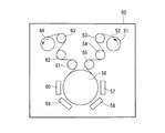
本実施の形態に係る真空成膜装置(スパッタリングウェブコータ)は、図3に示すように真空チャンバー(減圧室)50内に、長尺状耐熱性樹脂フィルム52を巻き出す巻き出しロール51と、長尺状耐熱性樹脂フィルム52を巻き取る巻き取りロール64と、巻き出しロール51と巻き取りロール64間に設けられかつ内部で温調された冷媒が循環していると共にサーボモータにより回転駆動される冷却キャンロール56と、冷却キャンロール56の上流側に設けられかつサーボモータにより回転駆動されると共に巻き出しロール51から供給された長尺状耐熱性樹脂フィルム52を冷却キャンロール56に搬入させる前フィードロール55と、冷却キャンロール56の下流側に設けられかつサーボモータにより回転駆動されると共に冷却キャンロール56から送り出される長尺状耐熱性樹脂フィルム52を上記巻き取りロール64側へ搬出させる後フィードロール61が配置された構造を有しており、かつ、上記冷却キャンロール56の対向側には熱負荷を伴う真空成膜手段としてのマグネトロンスパッタリングカソード57、58、59、60が冷却キャンロール56の外周面に沿って設けられている。尚、冷却キャンロール56については、回転軸を構成する金属材料よりその熱膨張係数が大きい金属材料を用いて円筒部を構成した上述のキャンロールが用いられている。
A vacuum film forming apparatus (sputtering web coater) according to the present embodiment includes an unwinding
また、巻き出しロール51から冷却キャンロール56までの上流側搬送路上には、長尺状耐熱性樹脂フィルム52を案内するフリーロール53と、長尺状耐熱性樹脂フィルム52の張力測定を行う張力センサロール54と、サーボモータにて回転駆動される前フィードロール55がそれぞれ配置されている。
Further, on the upstream conveyance path from the unwinding
そして、サーボモータにて回転駆動される冷却キャンロール56に対しその周速度が遅くなるように調整された前フィードロール55により長尺状耐熱性樹脂フィルム52が冷却キャンロール56の外周面に密着し搬送されるようになっている。
Then, the long heat-
また、上記冷却キャンロール56から巻き取りロール64までの下流側搬送路上にも、サーボモータにて回転駆動される後フィードロール61と、長尺状耐熱性樹脂フィルム52の張力測定を行う張力センサロール62と、長尺状耐熱性樹脂フィルム52を案内するフリーロール63がそれぞれ配置されている。
Also, a tension sensor that measures the tension of the
そして、冷却キャンロール56に対しその周速度が同一若しくは速くなるように調整された上記後フィードロール61により冷却キャンロール56から巻き取りロール64側に向けて長尺状耐熱性樹脂フィルム52が排出されるようになっている。
Then, the long heat-
また、上記巻き出しロール51と巻き取りロール64では、パウダークラッチ等によるトルク制御によって、長尺状耐熱性樹脂フィルム52の張力バランスが保たれるようになっている。更に、冷却キャンロール56の回転とこれに連動して回転するサーボモータ駆動の前フィードロール55と後フィードロール61により、巻き出しロール51から長尺状耐熱性樹脂フィルム52が巻き出されて上記巻き取りロール64に巻き取られるようになっている。
The unwinding
また、真空成膜装置(スパッタリングウェブコータ)では、上述したように熱負荷を伴う真空成膜手段としてのマグネトロンスパッタリングカソード57、58、59、60が上記冷却キャンロール56の外周面に沿って設けられている。
Further, in the vacuum film forming apparatus (sputtering web coater), as described above, the
そして、スパッタリング成膜に際しては、スパッタリングウェブコータの減圧室内を到達圧力10-4Pa程度まで減圧した後、スパッタリングガスの導入により0.1〜10Pa程度の圧力調整が行われる。スパッタリングガスにはアルゴン等公知のガスが使用され、目的に応じて更に酸素等のガスが添加される。真空成膜装置(スパッタリングウェブコータ)の形状や材質に関しては、減圧状態に耐え得るものであれば特に限定はなく、種々のものが使用される。また、スパッタリングウェブコータにおける減圧室内の減圧状態を維持するため、スパッタリングウェブコータには、図示しないドライポンプ、ターボ分子ポンプ、クライオコイル等の種々の装置が付設されている。 In sputtering film formation, the pressure inside the reduced pressure chamber of the sputtering web coater is reduced to an ultimate pressure of about 10 −4 Pa, and then the pressure is adjusted to about 0.1 to 10 Pa by introducing a sputtering gas. A known gas such as argon is used as the sputtering gas, and a gas such as oxygen is further added depending on the purpose. The shape and material of the vacuum film forming apparatus (sputtering web coater) are not particularly limited as long as they can withstand a reduced pressure state, and various types can be used. In order to maintain the reduced pressure state in the reduced pressure chamber of the sputtering web coater, the sputtering web coater is provided with various devices such as a dry pump, a turbo molecular pump, and a cryocoil (not shown).
尚、金属膜のスパッタリング成膜の場合には、板状のターゲット(図示せず)を使用することができるが、板状ターゲットを用いた場合、ターゲット上にノジュール(異物の成長)が発生することがある。これが問題となる場合には、ノジュールの発生がなく、ターゲットの使用効率が高い円筒形のロータリーターゲットを使用することが好ましい。また、図3に示す真空成膜装置(スパッタリングウェブコータ)は、熱負荷を伴う真空成膜手段としてスパッタリングを想定したものであることからマグネトロンスパッタリングカソード57、58、59、60が示されているが、熱負荷を伴う真空成膜手段が蒸着等の他の成膜手段である場合は、板状ターゲットに代えて他の成膜手段が設けられる。他の真空成膜手段としては、CVD(化学的気相成長)および蒸着法等が例示される。
In the case of sputtering a metal film, a plate-like target (not shown) can be used. However, when a plate-like target is used, nodules (foreign material growth) are generated on the target. Sometimes. When this becomes a problem, it is preferable to use a cylindrical rotary target that generates no nodules and has high target use efficiency. Further, since the vacuum film forming apparatus (sputtering web coater) shown in FIG. 3 assumes sputtering as a vacuum film forming means with a thermal load,
(3)長尺体と金属膜付耐熱性樹脂フィルム
(3-1)長尺体
長尺体は、長尺状の樹脂フィルム、金属箔、金属ストリップ等が挙げられる。そして、樹脂フィルムとしては、ポリエチレンテレフタレート(PET)フィルムのような長尺状樹脂フィルムや、ポリイミドフィルムのような長尺状耐熱性樹脂フィルム等が例示される。
(3) Long body and heat resistant resin film with metal film (3-1) Long body Examples of the long body include a long resin film, metal foil, and metal strip. Examples of the resin film include a long resin film such as a polyethylene terephthalate (PET) film, a long heat resistant resin film such as a polyimide film, and the like.
(3-2)金属膜付耐熱性樹脂フィルム(銅張積層樹脂フィルム基板)
本発明に係る長尺体の成膜方法を用いて、金属膜付耐熱性樹脂フィルム(銅張積層樹脂フィルム基板)を製造することができる。
(3-2) Heat-resistant resin film with metal film (copper-clad laminated resin film substrate)
A heat-resistant resin film with a metal film (copper-clad laminated resin film substrate) can be produced using the method for forming a long body according to the present invention.
上記金属膜付耐熱性樹脂フィルム(銅張積層樹脂フィルム基板)としては、耐熱性樹脂フィルム表面にNi、Ni系合金、クロム等からなる下地金属層と、下地金属層の表面に積層された銅薄膜層とで構成された構造体が例示される。このような構造を有する銅張積層樹脂フィルム基板は、サブトラクティブ法によりフレキシブル配線基板に加工される。ここで、サブトラクティブ法とは、レジストで覆われていない金属膜(例えば、上記銅薄膜層)をエッチングにより除去してフレキシブル配線基板を製造する方法である。 As the heat-resistant resin film with metal film (copper-clad laminated resin film substrate), a base metal layer made of Ni, Ni-based alloy, chromium, etc. on the surface of the heat-resistant resin film, and copper laminated on the surface of the base metal layer A structure composed of a thin film layer is exemplified. The copper clad laminated resin film substrate having such a structure is processed into a flexible wiring substrate by a subtractive method. Here, the subtractive method is a method of manufacturing a flexible wiring board by removing a metal film (for example, the copper thin film layer) not covered with a resist by etching.
上記Ni合金等からなる層はシード層(下地金属層)と呼ばれ、銅張積層樹脂フィルム基板の電気絶縁性や耐マイグレーション性等の所望の特性によりその組成が選択される。そして、シード層には、Ni−Cr合金またはインコネル、コンズタンタンやモネル等の各種公知の合金を用いることができる。また、金属膜付耐熱性樹脂フィルム(銅張積層樹脂フィルム基板)の金属膜(銅薄膜層)を更に厚くしたい場合は、湿式めっき法を用いて金属膜を形成することがある。尚、電気めっき処理(すなわち、電解めっき処理)のみで金属膜を形成する場合と、一次めっきとして無電解めっき処理を行い、二次めっきとして電解めっき処理等の湿式めっき法を組み合わせて行う場合もある。湿式めっき処理は、常法による湿式めっき法の諸条件を採用すればよい。 The layer made of Ni alloy or the like is called a seed layer (underlying metal layer), and its composition is selected depending on desired characteristics such as electrical insulation and migration resistance of the copper-clad laminated resin film substrate. The seed layer can be made of various known alloys such as Ni—Cr alloy or Inconel, Condanthan, Monel and the like. Moreover, when it is desired to further increase the thickness of the metal film (copper thin film layer) of the heat-resistant resin film with metal film (copper-clad laminated resin film substrate), the metal film may be formed using a wet plating method. There are cases where a metal film is formed only by electroplating (ie, electroplating), and electroless plating is performed as primary plating and wet plating such as electrolytic plating is combined as secondary plating. is there. The wet plating process may employ various conditions of a conventional wet plating method.
また、上記金属膜付耐熱性樹脂フィルム(銅張積層樹脂フィルム基板)に用いる耐熱性樹脂フィルムとしては、例えば、ポリイミド系フィルム、ポリアミド系フィルム、ポリエステル系フィルム、ポリテトラフルオロエチレン系フィルム、ポリフェニレンサルファイド系フィルム、ポリエチレンナフタレート系フィルムまたは液晶ポリマー系フィルムから選ばれる樹脂フィルムが挙げられ、金属膜付耐熱性樹脂フィルム(銅張積層樹脂フィルム)としての柔軟性、実用上必要な強度、配線材料として好適な電気絶縁性を有する点から好ましい。 Moreover, as a heat resistant resin film used for the said heat resistant resin film with a metal film (copper clad laminated resin film substrate), for example, polyimide film, polyamide film, polyester film, polytetrafluoroethylene film, polyphenylene sulfide Resin film selected from polyethylene film, polyethylene naphthalate film or liquid crystal polymer film, flexibility as heat-resistant resin film with metal film (copper-clad laminated resin film), practically necessary strength, as wiring material It is preferable from the viewpoint of having suitable electrical insulation.
尚、上記金属膜付耐熱性樹脂フィルム(銅張積層樹脂フィルム)として、長尺耐熱性樹脂フィルムにNi-Cr合金やCu等の金属膜を積層した構造体を例示したが、上記金属膜以外に、目的に応じて酸化物膜、窒化物膜、炭化物膜等を用いることも可能である。 In addition, as the heat-resistant resin film with a metal film (copper-clad laminated resin film), a structure in which a metal film such as a Ni—Cr alloy or Cu is laminated on a long heat-resistant resin film is exemplified. In addition, an oxide film, a nitride film, a carbide film, or the like can be used depending on the purpose.
以下、本発明の実施例について比較例も挙げて具体的に説明するが、本発明に係る技術的構成が下記実施例の構成に限定されるものではない。 Hereinafter, examples of the present invention will be specifically described with reference to comparative examples, but the technical configuration according to the present invention is not limited to the configurations of the following examples.
まず、本実施例においては図3に示した真空成膜装置(スパッタリングウェブコータ)を用い、長尺体としての耐熱性樹脂フィルム52には、幅500mm、長さ800m、厚さ25μmの宇部興産株式会社製の耐熱性ポリイミドフィルム「ユーピレックス(登録商標)」を使用した。
First, in this embodiment, the vacuum film forming apparatus (sputtering web coater) shown in FIG. 3 is used, and the heat-
また、真空成膜装置(スパッタリングウェブコータ)に組み込まれたキャンロールは、当該ロールの使用想定温度(20℃)条件下で円筒部が回転軸と平行(すなわち、円筒部外周面の軸方向中央部直径α1と両端部直径α2が同一に設定)になるよう切削研磨加工された平行形状型キャンロールを適用し、上記中央部直径α1と両端部直径α2が900mm、幅750mm、かつ、キャンロール本体(円筒部)表面にハードクロムめっきが施されている。 In addition, the can roll incorporated in the vacuum film forming apparatus (sputtering web coater) has the cylindrical portion parallel to the rotation axis under the assumed use temperature (20 ° C.) of the roll (that is, the axial center of the outer peripheral surface of the cylindrical portion). Applying a parallel-shaped can roll that has been cut and polished so that the part diameter α1 and the both end diameters α2 are set to be the same), the central part diameter α1 and both end diameters α2 are 900 mm, the width is 750 mm, and the can roll Hard chrome plating is applied to the surface of the main body (cylindrical part).
また、キャンロールの円筒部と回転軸を構成する金属材料には、熱膨張係数の大きいアルミニウム(線熱膨張係数:23ppm/K)と熱膨張係数の小さいステンレス(線熱膨張係数:15ppm/K)を適用し、以下の表1〜表4に示すように、円筒部と回転軸がそれぞれステンレスで構成されたキャンロール、円筒部と回転軸がそれぞれアルミニウム(アルミ)で構成されたキャンロール、および、熱膨張係数の大きいアルミで円筒部が構成されかつ熱膨張係数の小さいステンレスで回転軸が構成されたキャンロール3種を作製し、更に、3種のキャンロールそれぞれについて、回転軸の温度を20℃に制御する回転軸用冷却手段が付設されたキャンロールと冷却手段が付設されないキャンロールを作製した。 In addition, the metal material constituting the cylindrical portion of the can roll and the rotating shaft includes aluminum having a large thermal expansion coefficient (linear thermal expansion coefficient: 23 ppm / K) and stainless steel having a small thermal expansion coefficient (linear thermal expansion coefficient: 15 ppm / K). ), And as shown in Tables 1 to 4 below, the cylindrical portion and the rotating shaft can each be made of stainless steel, the cylindrical portion and the rotating shaft can be made of aluminum (aluminum), respectively. Also, three types of can rolls having a cylindrical portion made of aluminum having a large thermal expansion coefficient and a rotating shaft made of stainless steel having a small thermal expansion coefficient are manufactured. Further, for each of the three types of can rolls, the temperature of the rotating shaft is prepared. A can roll provided with a cooling means for a rotating shaft for controlling the temperature at 20 ° C. and a can roll provided with no cooling means were prepared.
また、上記回転軸用冷却手段が付設された3種のキャンロール(実施例1〜3)、および、熱膨張係数の大きいアルミで円筒部が構成されかつ熱膨張係数の小さいステンレスで回転軸が構成されると共に上記回転軸用冷却手段が付設されていないキャンロール(実施例4)をそれぞれ実施例に係るキャンロールとし、円筒部と回転軸がそれぞれステンレスで構成されかつ上記回転軸用冷却手段が付設されていないキャンロール(比較例1)、および、円筒部と回転軸がそれぞれアルミニウム(アルミ)で構成されかつ上記回転軸用冷却手段が付設されていないキャンロール(比較例2)をそれぞれ比較例に係るキャンロールとした。 In addition, the three types of can rolls (Examples 1 to 3) to which the cooling means for the rotating shaft is attached, and the cylindrical portion is made of aluminum having a large thermal expansion coefficient and the rotating shaft is made of stainless steel having a small thermal expansion coefficient. The can roll (Embodiment 4) that is configured and not provided with the rotating shaft cooling means is a can roll according to the embodiment, the cylindrical portion and the rotating shaft are each made of stainless steel, and the rotating shaft cooling means Can rolls (Comparative Example 1) that are not provided with a cylindrical part and a rotating shaft that is made of aluminum (aluminum) and are not provided with cooling means for the rotating shaft (Comparative Example 2). It was set as the can roll which concerns on a comparative example.
そして、実施例1〜4に係るキャンロールと比較例1〜2に係るキャンロールについて、下記温度(20℃、40℃、60℃)条件下で使用されたときの「軸方向中央部直径α1と両端部直径α2の直径差(α=α1−α2)で定義されるクラウン量(μm)」、および、「皺が発生しない最大スパッタ電力(4台の合計)kW」をそれぞれ実験により求めた。 And about the can roll which concerns on Examples 1-4 and the can roll which concerns on Comparative Examples 1-2, when used on the following temperature (20 degreeC, 40 degreeC, 60 degreeC) conditions, "the axial direction center part diameter (alpha) 1. And “the crown amount (μm) defined by the diameter difference between the two end diameters α2 (α = α1−α2)” and “the maximum sputter power (total of four units) kW at which no wrinkle is generated” were obtained by experiments. .
[クラウン量の比較]
実施例1〜4と比較例1〜2に係るキャンロールについて、20℃、40℃、60℃の温度(各キャンロールの円筒部外周面温度に基づく)条件下で使用されたときのクラウン量(キャンロールの外周面形状)を測定した。
[Comparison of crown amount]
About the can roll which concerns on Examples 1-4 and Comparative Examples 1-2, the crown amount when it is used on the conditions (based on the cylindrical part outer peripheral surface temperature of each can roll) of 20 degreeC, 40 degreeC, and 60 degreeC (The outer peripheral surface shape of the can roll) was measured.
尚、各キャンロールにおける円筒部外周面温度については、図4の符号33、図6の符号43で示される内側導入管から20℃の冷水、40℃、60℃の温水を各キャンロールに個別に注入して各キャンロールの円筒部外周面温度としている。
In addition, about the cylindrical part outer peripheral surface temperature in each can roll, 20 degreeC cold water, 40 degreeC, and 60 degreeC hot water are separately supplied to each can roll from the inner introduction pipe shown by the code | symbol 33 of FIG. 4, the code |
その結果を以下の表1と表2に示す。 The results are shown in Tables 1 and 2 below.

[評 価]
(1)実施例1と比較例1、実施例2と比較例2、および、実施例3と実施例4との比較から確認されるように、上記回転軸用冷却手段が付設されていない比較例1、比較例2、および、実施例4に係るキャンロールにおいては、円筒部の温度が回転軸に伝熱してしまうことから、上記回転軸用冷却手段が付設された実施例1〜3に係るキャンロールと比較してクラウン量が小さいことが確認される。特に、比較例1に係るキャンロールにおいては、使用想定温度を大きく超えた温度条件下で使用された場合、当該使用温度に対応可能な十分なクラウン量を確保し難いことが確認される。
[Evaluation]
(1) Comparison in which the cooling means for the rotating shaft is not provided as confirmed from the comparison between the first embodiment and the first comparative example, the second embodiment and the second comparative example, and the third embodiment and the fourth embodiment. In the can roll according to Example 1, Comparative Example 2, and Example 4, since the temperature of the cylindrical portion is transferred to the rotating shaft, the rotating shaft cooling means is attached to Examples 1-3. It is confirmed that the crown amount is smaller than that of the can roll. In particular, in the can roll according to Comparative Example 1, when it is used under a temperature condition that greatly exceeds the assumed use temperature, it is confirmed that it is difficult to secure a sufficient crown amount that can correspond to the use temperature.
(2)円筒部の材質に熱膨張係数の大きいアルミニウムが適用された場合、ステンレスが適用された場合と比較してクラウン量が大きくなることも確認される。 (2) It is also confirmed that when aluminum having a large thermal expansion coefficient is applied to the material of the cylindrical portion, the crown amount becomes larger than when stainless steel is applied.
[皺が発生しない最大スパッタ電力]
次に、実施例1〜4と比較例1〜2に係るキャンロールが個別に組み込まれた実施例1〜4と比較例1〜2に係る真空成膜装置(スパッタリングウェブコータ)を用い、耐熱性樹脂フィルム(耐熱性ポリイミドフィルム)52に対しシード層(下地金属層)のNi−Cr膜とCu膜を順次成膜したときに皺が発生しない最大スパッタ電力を測定した。
[Maximum spatter power without soot]
Next, using the vacuum film-forming apparatus (sputtering web coater) which concerns on Examples 1-4 and Comparative Examples 1-2 in which the can roll concerning Examples 1-4 and Comparative Examples 1-2 was integrated separately, it was heat-resistant. When the Ni—Cr film and the Cu film of the seed layer (underlying metal layer) were sequentially formed on the conductive resin film (heat resistant polyimide film) 52, the maximum sputtering power at which no wrinkle was generated was measured.
尚、成膜条件は以下の通りである。 The film forming conditions are as follows.
すなわち、図3に示すマグネトロンスパッタターゲット57にはNi−Crターゲットを用い、マグネトロンスパッタターゲット58、59、60にはCuターゲットを用い、アルゴンガスを300sccm導入し、各カソードへの印加電力は5kWの電力制御で行った。また、巻き出しロール51と巻き取りロール64の張力は80Nとし、巻き出しロール51に上記耐熱性樹脂フィルム(耐熱性ポリイミドフィルム)52をセットし、かつ、キャンロール56を経由して耐熱性樹脂フィルム(耐熱性ポリイミドフィルム)52の先端部を巻き取りロール64に取り付けた。また、真空チャンバー50を複数台のドライポンプにより5Paまで排気した後、更に、複数台のターボ分子ポンプとクライオコイルを用いて3×10⁻³Paまで排気した。
That is, a Ni—Cr target is used for the
次に、上記耐熱性樹脂フィルム(耐熱性ポリイミドフィルム)52の搬送速度を3m/分にした後、各マグネトロンスパッタカソード57、58、59、60にアルゴンガスを導入して電力を印加し、Ni−Cr膜とCu膜の成膜を開始した。
Next, after the conveyance speed of the heat-resistant resin film (heat-resistant polyimide film) 52 was set to 3 m / min, argon gas was introduced into each of the
そして、実施例1〜4と比較例1〜2に係る各真空成膜装置(スパッタリングウェブコータ)におけるキャンロール56上の耐熱性樹脂フィルム(耐熱性ポリイミドフィルム)表面を観察可能な窓から、実施例1〜4と比較例1〜2に係るキャンロールの円筒部における制御温度(20℃、40℃、60℃)条件下、搬送速度3m/分でキャンロール56上を搬送される耐熱性樹脂フィルム(耐熱性ポリイミドフィルム)の皺発生の有無を観察すると共に、スパッタリングの熱負荷に起因した皺発生が起こらない最大スパッタ電力(4台の合計)を求めた。 And it implemented from the window which can observe the heat resistant resin film (heat resistant polyimide film) surface on the can roll 56 in each vacuum film-forming apparatus (sputtering web coater) which concerns on Examples 1-4 and Comparative Examples 1-2. Heat-resistant resin conveyed on the can roll 56 at a conveyance speed of 3 m / min under the control temperature (20 ° C., 40 ° C., 60 ° C.) conditions in the cylindrical portion of the can roll according to Examples 1-4 and Comparative Examples 1-2. The film (heat-resistant polyimide film) was observed for the presence or absence of wrinkle generation, and the maximum sputter power (total of four units) at which wrinkle generation due to the thermal load of sputtering did not occur was determined.
その結果を以下の表3と表4に示す。 The results are shown in Tables 3 and 4 below.
[評 価]
(1)実施例1〜3に係る「表1」と「表3」、および、比較例1〜2と実施例4に係る「表2」と「表4」との対比で確認されるように、「クラウン量」と「皺が発生しない最大スパッタ電力」は略比例関係にあり、かつ、「クラウン量」が大きくなると「皺が発生しない最大スパッタ電力」も大きくなる傾向にあった。
[Evaluation]
(1) It is confirmed by comparing “Table 1” and “Table 3” according to Examples 1 to 3 and “Table 2” and “Table 4” according to Comparative Examples 1 and 2 and Example 4. In addition, “crown amount” and “maximum sputter power at which no soot is generated” are in a substantially proportional relationship, and “maximum sputter power at which no soot is generated” tends to increase as “crown amount” increases.
これは、キャンロールのクラウン形状により上述した「中だるみ状態」が解消され、耐熱性樹脂フィルム(耐熱性ポリイミドフィルム)とキャンロールの密着性が向上し、スパッタリングによる熱負荷がキャンロールにより効率よく冷却されたためと考えられる。 This eliminates the above-mentioned “sagging state” due to the crown shape of the can roll, improves the adhesion between the heat resistant resin film (heat resistant polyimide film) and the can roll, and efficiently cools the thermal load due to sputtering by the can roll. It is thought that it was because it was done.
(2)また、各表に示していないが、キャンロール円筒部の制御温度が80℃を超えた場合、皺が発生しない最大スパッタ電力は極端に低下する傾向にあった。 (2) Moreover, although not shown in each table | surface, when the control temperature of the can-roll cylindrical part exceeded 80 degreeC, there existed a tendency for the maximum sputter | spatter electric power which a wrinkle does not generate to fall extremely.
これは、上記キャンロールの冷却効果(クラウン形状により「中だるみ状態」が解消され、耐熱性樹脂フィルムとキャンロールの密着性が向上してスパッタリングによる熱負荷がキャンロールにより効率よく冷却される効果)に較べ、キャンロールの温度が高過ぎる(80℃を超えている場合)結果、耐熱性樹脂フィルムの冷却作用が不十分となる影響の方が大きいためであると考えられる。 This is the cooling effect of the above can roll (the effect that the “sagging state” is eliminated by the crown shape, the adhesion between the heat resistant resin film and the can roll is improved, and the thermal load due to sputtering is efficiently cooled by the can roll) In comparison, the temperature of the can roll is too high (when it exceeds 80 ° C.), and as a result, the effect of the cooling effect of the heat resistant resin film becoming insufficient is considered to be larger.
(3)上記キャンロールの温度が高過ぎる弊害を回避するためには、使用想定温度におけるキャンロール表面形状を若干のクラウン形状に切削研磨加工しておく(すなわち、クラウン量を必要以上に大きく設定しない)ことで、最適なクラウン量になる円筒部の制御温度を低下させることが可能になる。 (3) In order to avoid the adverse effect of the temperature of the can roll being too high, the surface of the can roll at the assumed use temperature is cut and polished into a slight crown shape (that is, the crown amount is set larger than necessary). Not), it becomes possible to lower the control temperature of the cylindrical portion that achieves the optimum crown amount.
(4)一方、使用想定温度におけるキャンロール表面形状を大きなクラウン形状に切削研磨加工(すなわち、クラウン量を大きく設定する)し、キャンロール円筒部の制御温度を低下させてクラウン量を減少させる方法は、スパッタリング成膜前にキャンロールで冷却された樹脂フィルムとスパッタリングの熱負荷によるフィルム表面の温度差が大きくなって急激な熱歪みによる皺が発生してしまうことがある。 (4) On the other hand, a method of cutting and polishing the surface of the can roll at the assumed use temperature into a large crown shape (that is, setting the crown amount large) and lowering the control temperature of the can roll cylindrical portion to reduce the crown amount In some cases, the temperature difference between the resin film cooled by a can roll before sputtering film formation and the film surface due to the thermal load of sputtering becomes large and wrinkles due to rapid thermal distortion may occur.
本発明に係るキャンロールによれば、成膜速度を高める等の理由で使用想定温度を大きく超えた温度条件で使用された場合においても十分なクラウン量を確保できるため、耐熱性樹脂フィルム等の皺発生を抑制することが可能となる。このため、液晶テレビ、携帯電話等のフレキシブル配線基板に用いられる銅張積層樹脂フィルム(金属膜付耐熱性樹脂フィルム)の製造に使用される産業上の利用可能性を有している。 According to the can roll according to the present invention, a sufficient crown amount can be secured even when used under a temperature condition that greatly exceeds the assumed use temperature for reasons such as increasing the film formation rate. It becomes possible to suppress wrinkle generation. For this reason, it has the industrial applicability used for manufacture of the copper clad laminated resin film (heat resistant resin film with a metal film) used for flexible wiring boards, such as a liquid crystal television and a mobile phone.
30 円筒部
31 回転軸
32 側板
33 内側導入管
34 外側排出管
35 ベアリング
40 円筒部
41 回転軸
42 側板
43 内側導入管
44 外側排出管
45 ベアリング
46 回転軸冷媒導入管
47 回転軸冷媒排出管
50 真空チャンバー(減圧室)
51 巻き出しロール
52 長尺状耐熱性樹脂フィルム
53 フリーロール
54 張力センサロール
55 前フィードロール
56 キャンロール
57 マグネトロンスパッタリングカソード
58 マグネトロンスパッタリングカソード
59 マグネトロンスパッタリングカソード
60 マグネトロンスパッタリングカソード
61 後フィードロール
62 張力センサロール
63 フリーロール
64 巻き取りロール
70 円筒部
71 回転軸
DESCRIPTION OF
51
Claims (7)
上記回転軸を構成する金属材料よりその熱膨張係数が大きい金属材料を用いて円筒部が構成されていることを特徴とするキャンロール。 It has a cylindrical part with a refrigerant circulation path inside and a rotating shaft provided at the center of rotation of the cylindrical part, and a long body that is conveyed by roll-to-roll in a vacuum chamber is wound around the outer peripheral surface of the cylindrical part In the can roll that cools
A can roll characterized in that the cylindrical portion is made of a metal material having a larger thermal expansion coefficient than the metal material constituting the rotating shaft.
上記回転軸の温度を一定に制御する回転軸用の冷却手段が設けられていることを特徴とするキャンロール。 It has a cylindrical part with a refrigerant circulation path inside and a rotating shaft provided at the center of rotation of the cylindrical part, and a long body that is conveyed by roll-to-roll in a vacuum chamber is wound around the outer peripheral surface of the cylindrical part In the can roll that cools
A can roll, characterized in that a cooling means for the rotary shaft for controlling the temperature of the rotary shaft to be constant is provided.
請求項1〜4のいずれかに記載のキャンロールで上記キャンロールが構成されていることを特徴とする真空成膜装置。 A vacuum chamber, a transport mechanism that transports a long body in a roll-to-roll manner in the vacuum chamber, a can roll that winds and cools the long body around the outer peripheral surface, and a vacuum against the long body wound around the can roll In a vacuum film forming apparatus provided with means for performing film formation,
The vacuum film-forming apparatus characterized by the said can roll being comprised with the can roll in any one of Claims 1-4.
請求項1〜4のいずれかに記載のキャンロールで上記キャンロールが構成されていることを特徴とする長尺体の成膜方法。 In a film forming method of a long body that wraps a long body conveyed by roll-to-roll in a vacuum chamber around the outer peripheral surface of the can roll and performs vacuum film formation on the long body wound around the can roll,
The can roll according to any one of claims 1 to 4, wherein the can roll is constituted.
Priority Applications (1)
| Application Number | Priority Date | Filing Date | Title |
|---|---|---|---|
| JP2016007764A JP6544249B2 (en) | 2016-01-19 | 2016-01-19 | CAN ROLL, VACUUM FILM FORMING APPARATUS, AND FILM FORMING METHOD OF LONG BODY |
Applications Claiming Priority (1)
| Application Number | Priority Date | Filing Date | Title |
|---|---|---|---|
| JP2016007764A JP6544249B2 (en) | 2016-01-19 | 2016-01-19 | CAN ROLL, VACUUM FILM FORMING APPARATUS, AND FILM FORMING METHOD OF LONG BODY |
Related Child Applications (1)
| Application Number | Title | Priority Date | Filing Date |
|---|---|---|---|
| JP2019080998A Division JP6721079B2 (en) | 2019-04-22 | 2019-04-22 | Can roll, vacuum film forming apparatus, and long film forming method |
Publications (2)
| Publication Number | Publication Date |
|---|---|
| JP2017128754A true JP2017128754A (en) | 2017-07-27 |
| JP6544249B2 JP6544249B2 (en) | 2019-07-17 |
Family
ID=59394580
Family Applications (1)
| Application Number | Title | Priority Date | Filing Date |
|---|---|---|---|
| JP2016007764A Expired - Fee Related JP6544249B2 (en) | 2016-01-19 | 2016-01-19 | CAN ROLL, VACUUM FILM FORMING APPARATUS, AND FILM FORMING METHOD OF LONG BODY |
Country Status (1)
| Country | Link |
|---|---|
| JP (1) | JP6544249B2 (en) |
Citations (9)
| Publication number | Priority date | Publication date | Assignee | Title |
|---|---|---|---|---|
| JPH0765373A (en) * | 1993-08-27 | 1995-03-10 | Kao Corp | Magnetic recording medium manufacturing equipment |
| JPH09181005A (en) * | 1995-12-22 | 1997-07-11 | Canon Inc | Method and apparatus for forming deposited film |
| JPH09212862A (en) * | 1996-01-31 | 1997-08-15 | Sony Corp | Vapor deposition type magnetic tape manufacturing equipment |
| JPH10298764A (en) * | 1996-09-10 | 1998-11-10 | Hitachi Maxell Ltd | Plasma CVD equipment |
| JP2006283135A (en) * | 2005-03-31 | 2006-10-19 | Dainippon Printing Co Ltd | Film forming apparatus and film forming method |
| JP2012144798A (en) * | 2011-01-14 | 2012-08-02 | Sumitomo Metal Mining Co Ltd | Can roll, and device and method for treating long resin film substrate |
| JP2013237896A (en) * | 2012-05-15 | 2013-11-28 | Sumitomo Metal Mining Co Ltd | Device and method for treating surface of long-sized body, and method for manufacturing resin film substrate laminated with copper-clad |
| JP2014119092A (en) * | 2012-12-19 | 2014-06-30 | Sumitomo Metal Mining Co Ltd | Metal roll, process of manufacture thereof, and surface treatment device using metal roll |
| JP2014234541A (en) * | 2013-06-04 | 2014-12-15 | 住友金属鉱山株式会社 | Metal roll and method of manufacturing the same, and apparatus for processing long resin film including the metal roll |
-
2016
- 2016-01-19 JP JP2016007764A patent/JP6544249B2/en not_active Expired - Fee Related
Patent Citations (9)
| Publication number | Priority date | Publication date | Assignee | Title |
|---|---|---|---|---|
| JPH0765373A (en) * | 1993-08-27 | 1995-03-10 | Kao Corp | Magnetic recording medium manufacturing equipment |
| JPH09181005A (en) * | 1995-12-22 | 1997-07-11 | Canon Inc | Method and apparatus for forming deposited film |
| JPH09212862A (en) * | 1996-01-31 | 1997-08-15 | Sony Corp | Vapor deposition type magnetic tape manufacturing equipment |
| JPH10298764A (en) * | 1996-09-10 | 1998-11-10 | Hitachi Maxell Ltd | Plasma CVD equipment |
| JP2006283135A (en) * | 2005-03-31 | 2006-10-19 | Dainippon Printing Co Ltd | Film forming apparatus and film forming method |
| JP2012144798A (en) * | 2011-01-14 | 2012-08-02 | Sumitomo Metal Mining Co Ltd | Can roll, and device and method for treating long resin film substrate |
| JP2013237896A (en) * | 2012-05-15 | 2013-11-28 | Sumitomo Metal Mining Co Ltd | Device and method for treating surface of long-sized body, and method for manufacturing resin film substrate laminated with copper-clad |
| JP2014119092A (en) * | 2012-12-19 | 2014-06-30 | Sumitomo Metal Mining Co Ltd | Metal roll, process of manufacture thereof, and surface treatment device using metal roll |
| JP2014234541A (en) * | 2013-06-04 | 2014-12-15 | 住友金属鉱山株式会社 | Metal roll and method of manufacturing the same, and apparatus for processing long resin film including the metal roll |
Also Published As
| Publication number | Publication date |
|---|---|
| JP6544249B2 (en) | 2019-07-17 |
Similar Documents
| Publication | Publication Date | Title |
|---|---|---|
| US11261520B2 (en) | Roll-to-roll surface treatment device, and film deposition method and film deposition device using same | |
| JP6060854B2 (en) | Surface treatment method for resin film and method for producing copper clad laminate including the same | |
| US20210230742A1 (en) | Gas discharge roll and manufacturing method for same, and processing apparatus using gas discharge roll | |
| JP5741522B2 (en) | Long surface treatment apparatus, surface treatment method, and copper clad laminated resin film substrate manufacturing method | |
| JP5573637B2 (en) | Long substrate processing apparatus and processing method provided with gas introduction mechanism, and long substrate transfer method | |
| EP3495534B1 (en) | Long substrate treatment apparatus and treatment method | |
| JP5488477B2 (en) | Can roll, long resin film substrate processing apparatus and processing method | |
| US11352697B2 (en) | Apparatus for processing long base material by roll-to-roll method and film forming apparatus using the same | |
| JP6508080B2 (en) | Can roll and long body processing apparatus and method | |
| JP5310486B2 (en) | Method for forming long heat-resistant resin film and apparatus for producing heat-resistant resin film with metal film | |
| JP5849934B2 (en) | Vacuum film forming apparatus and vacuum film forming method | |
| JP5741517B2 (en) | Long surface treatment apparatus, surface treatment method, and copper clad laminated resin film substrate manufacturing method | |
| JP2013147701A (en) | Conveyance control method of long strip-like body and surface treatment method of the same | |
| JP6060836B2 (en) | Surface treatment method for resin film and method for producing copper clad laminate including the same | |
| JP6544249B2 (en) | CAN ROLL, VACUUM FILM FORMING APPARATUS, AND FILM FORMING METHOD OF LONG BODY | |
| JP6721079B2 (en) | Can roll, vacuum film forming apparatus, and long film forming method | |
| JP5527186B2 (en) | Long substrate processing apparatus and processing method provided with gas introduction mechanism | |
| JP5494466B2 (en) | Wrinkle stretching method and wrinkle stretching apparatus on can roll, and film forming apparatus provided with the same | |
| JP6201162B2 (en) | Can roll, long substrate processing apparatus, and long substrate processing method | |
| JP6269385B2 (en) | Can roll, long substrate processing apparatus, and long substrate processing method | |
| KR20180070572A (en) | A method for winding a long substrate and a winding device, and a surface treatment device for a long substrate having the winding device | |
| JP6575399B2 (en) | Roll-to-roll processing apparatus and processing method | |
| JP6683908B2 (en) | Vacuum film forming apparatus and vacuum film forming method | |
| JP5892029B2 (en) | Winding core, winding device having the same, and roll-to-roll surface treatment apparatus provided with the device | |
| JP6127771B2 (en) | Core adapter, winding device having the same, and roll-to-roll surface treatment apparatus provided with the device |
Legal Events
| Date | Code | Title | Description |
|---|---|---|---|
| A621 | Written request for application examination |
Free format text: JAPANESE INTERMEDIATE CODE: A621 Effective date: 20180523 |
|
| A977 | Report on retrieval |
Free format text: JAPANESE INTERMEDIATE CODE: A971007 Effective date: 20190124 |
|
| A131 | Notification of reasons for refusal |
Free format text: JAPANESE INTERMEDIATE CODE: A131 Effective date: 20190305 |
|
| A521 | Request for written amendment filed |
Free format text: JAPANESE INTERMEDIATE CODE: A523 Effective date: 20190422 |
|
| TRDD | Decision of grant or rejection written | ||
| A01 | Written decision to grant a patent or to grant a registration (utility model) |
Free format text: JAPANESE INTERMEDIATE CODE: A01 Effective date: 20190521 |
|
| A61 | First payment of annual fees (during grant procedure) |
Free format text: JAPANESE INTERMEDIATE CODE: A61 Effective date: 20190603 |
|
| R150 | Certificate of patent or registration of utility model |
Ref document number: 6544249 Country of ref document: JP Free format text: JAPANESE INTERMEDIATE CODE: R150 |
|
| LAPS | Cancellation because of no payment of annual fees |