JP2017141505A - Apparatus for manufacturing molded article and method for manufacturing molded article - Google Patents
Apparatus for manufacturing molded article and method for manufacturing molded article Download PDFInfo
- Publication number
- JP2017141505A JP2017141505A JP2016239031A JP2016239031A JP2017141505A JP 2017141505 A JP2017141505 A JP 2017141505A JP 2016239031 A JP2016239031 A JP 2016239031A JP 2016239031 A JP2016239031 A JP 2016239031A JP 2017141505 A JP2017141505 A JP 2017141505A
- Authority
- JP
- Japan
- Prior art keywords
- metal powder
- modeling
- light beam
- absorption rate
- irradiation
- Prior art date
- Legal status (The legal status is an assumption and is not a legal conclusion. Google has not performed a legal analysis and makes no representation as to the accuracy of the status listed.)
- Pending
Links
Images








Classifications
-
- Y—GENERAL TAGGING OF NEW TECHNOLOGICAL DEVELOPMENTS; GENERAL TAGGING OF CROSS-SECTIONAL TECHNOLOGIES SPANNING OVER SEVERAL SECTIONS OF THE IPC; TECHNICAL SUBJECTS COVERED BY FORMER USPC CROSS-REFERENCE ART COLLECTIONS [XRACs] AND DIGESTS
- Y02—TECHNOLOGIES OR APPLICATIONS FOR MITIGATION OR ADAPTATION AGAINST CLIMATE CHANGE
- Y02P—CLIMATE CHANGE MITIGATION TECHNOLOGIES IN THE PRODUCTION OR PROCESSING OF GOODS
- Y02P10/00—Technologies related to metal processing
- Y02P10/25—Process efficiency
Landscapes
- Powder Metallurgy (AREA)
Abstract
【課題】近赤外波長のレーザ光の吸収率が低い金属粉末材料であっても、低コストで積層造形による立体造形物の製作が可能な製造装置及び製造方法を提供する。【解決手段】製造装置100は、造形光ビームL1の照射によって金属粉末15を焼結又は溶融によって固化させ積層造形する造形物の製造装置であって、チャンバ10と、金属粉末15を照射範囲Ar1に供給する金属粉末供給装置20と、照射範囲Ar1の金属粉末15へ造形光ビームL1を照射する造形光ビーム照射装置30と、金属粉末15に対して所定の吸収率向上支援処理を行なう吸収率向上支援部40と、吸収率向上支援処理の実施後に、造形光ビームL1を照射し、金属粉末15を加熱し、焼結又は溶融によって固化させ積層造形する造形処理を行なう造形部70と、を備える。【選択図】図1Provided are a manufacturing apparatus and a manufacturing method capable of manufacturing a three-dimensional object by additive manufacturing at a low cost even with a metal powder material having a low absorptance of near infrared wavelength laser light. A manufacturing apparatus 100 is an apparatus for manufacturing a modeled object that is solidified by sintering or melting a metal powder 15 by irradiation with a modeling light beam L1, and irradiates a chamber 10 and the metal powder 15 with an irradiation range Ar1. The metal powder supply device 20 for supplying to the metal powder, the modeling light beam irradiation device 30 for irradiating the metal powder 15 in the irradiation range Ar1 with the modeling light beam L1, and the absorptance for performing a predetermined absorptivity improvement supporting process on the metal powder 15. After implementation of the improvement support unit 40 and the absorption rate improvement support process, the modeling unit 70 that performs the modeling process of irradiating the modeling light beam L1, heating the metal powder 15, solidifying by sintering or melting, and performing layered modeling. Prepare. [Selection] Figure 1
Description
本発明は、レーザ光を用い金属粉末を原料として積層造形物を製造する製造装置及び製造方法に関する。 The present invention relates to a manufacturing apparatus and a manufacturing method for manufacturing a layered object using metal powder as a raw material using laser light.
近年、粉末状の金属をレーザ光の照射によって焼結又溶融して固化させ、一層ずつ層状に積層して立体的な造形物を製造する金属AM(Additive Manufactuaring)の開発が盛んになってきている。このような金属AMでは、試作対応だけでなく、量産対応への検討も始まっている。金属AMで使用される金属には、主に安価なレーザ光である近赤外波長のレーザ光の吸収率がよいため低コストで製造が可能となるマルエージング鋼、ステンレス鋼(SUS)、及びチタン鋼(Ti)などがある。 In recent years, development of metal AM (Additive Manufacturing) has been actively developed in which a powdered metal is sintered or melted by laser light irradiation to be solidified and layered one by one to produce a three-dimensional shaped object. Yes. In such a metal AM, not only trial production but also examination for mass production has begun. The metals used in the metal AM include maraging steel, stainless steel (SUS), which can be manufactured at low cost because the absorption rate of near-infrared wavelength laser light, which is mainly inexpensive laser light, is good. Examples include titanium steel (Ti).
しかしながら、市場では、金属AMの金属粉末材料として、マルエージング鋼、ステンレス鋼(SUS)、及びチタン鋼(Ti)だけでなく、近赤外波長のレーザ光の吸収率が低い銅やアルミなども採用したいという要望が強くある。これに対し、特許文献1には、金属粉末材料をアルミとした、金属AMの技術が開示されている。特許文献1の技術では、アルミ粉末に、近赤外波長のレーザ光の吸収率が高いレーザ吸収剤を含ませている。これにより、近赤外波長のレーザ光が照射されると、まず、レーザ吸収剤に近赤外波長のレーザ光が吸収されて加熱され、その熱がアルミ粉末に伝導してアルミ粉末を加熱するとともに保温する。そして、このような環境において、さらにアルミ粉末を近赤外波長のレーザ光の照射とレーザ吸収剤からの熱によって加熱し溶融させると記載されている。
However, in the market, as metal powder material of metal AM, not only maraging steel, stainless steel (SUS), and titanium steel (Ti), but also copper and aluminum having a low absorption factor of laser light of near-infrared wavelength. There is a strong demand for adoption. On the other hand,
しかしながら、特許文献1の技術では、レーザ吸収剤自体がコストアップの要因となる虞がある。また、アルミ粉末と混在するレーザ吸収剤が不純物となり、製品の強度等によくない影響を及ぼす虞もある。
However, in the technique of
本発明は、上記課題に鑑みてなされたものであり、近赤外波長のレーザ光の吸収率が低い金属粉末材料であっても、低コストで積層造形による立体造形物の製作が可能な製造装置及び製造方法を提供することを目的とする。 The present invention has been made in view of the above problems, and is capable of producing a three-dimensional structure by additive manufacturing at a low cost even with a metal powder material having a low absorption rate of laser light of near-infrared wavelength. An object is to provide an apparatus and a manufacturing method.
上記課題を解決するため、本発明の請求項1に係る造形物の製造装置は、造形光ビームの照射によって金属粉末を焼結又は溶融によって固化させ積層造形する造形物の製造装置であって、外気と内気との遮断が可能なチャンバと、前記チャンバの内部に設けられ、前記金属粉末を前記造形光ビームの照射範囲に供給する金属粉末供給装置と、前記照射範囲に供給された前記チャンバ内の前記金属粉末へ前記造形光ビームを照射する造形光ビーム照射装置と、照射される前記造形光ビームの前記金属粉末への吸収率を向上させるため、前記金属粉末に対して所定の吸収率向上支援処理を行なう吸収率向上支援部と、前記吸収率向上支援処理の実施後に、前記造形光ビームを前記照射範囲に供給された前記金属粉末に照射し、前記金属粉末を加熱し、前記焼結又は前記溶融によって固化させ前記積層造形する造形処理を行なう造形部と、を備える。
In order to solve the above-mentioned problem, a manufacturing apparatus for a model according to
このように、造形物の製造装置は、吸収率向上支援部によって金属粉末に対する造形光ビームの吸収率を高める吸収率向上支援処理をおこなった後、造形光ビームを金属粉末に照射する。このため、造形光ビームは、金属粉末に良好に吸収される。従って、短時間の造形光ビームの照射によって金属粉末は良好に加熱され焼結又は溶融によって固化されるので積層造形する時間を短くすることができ、造形物を低コストに製造可能となる。 As described above, the manufacturing apparatus for a shaped article irradiates the metal powder with the modeling light beam after performing the absorption rate improvement supporting process for increasing the absorption rate of the modeling light beam with respect to the metal powder by the absorption rate improvement supporting unit. For this reason, the modeling light beam is well absorbed by the metal powder. Therefore, since the metal powder is heated well and solidified by sintering or melting by the irradiation of the modeling light beam for a short time, the time for the layered modeling can be shortened, and the modeled object can be manufactured at a low cost.
また、本発明の請求項23に係る造形物の製造方法は、造形光ビームの照射によって金属粉末を焼結又は溶融によって固化させ積層造形する造形物の製造方法であって、前記金属粉末を前記造形光ビームの照射範囲に供給する金属粉末供給工程と、照射される前記造形光ビームの前記金属粉末への吸収率を向上させるため、前記金属粉末に対して所定の吸収率向上支援処理を行なう吸収率向上支援工程と、前記吸収率向上支援処理の実施後に、前記造形光ビームを前記照射範囲に供給された前記金属粉末に照射し、前記金属粉末を加熱し、前記焼結又は前記溶融によって固化させ前記積層造形する造形処理を行なう造形工程と、を備える。これにより、請求項1で製造される造形物と同様の造形物が製作できる。
Moreover, the manufacturing method of the molded article according to
<1.第一実施形態>
(1−1.概要)
本発明に係る三次元造形物(造形物に相当)の製造装置について、図面に基づき説明する。三次元造形物の製造装置は、主に後に詳述する造形光ビームの照射によって金属粉末15を焼結又は溶融によって固化させ三次元造形物を積層造形する装置である。なお、本実施形態では、造形光ビームは、近赤外波長のレーザ光であり、以降、近赤外レーザ光L1と称す。
<1. First embodiment>
(1-1. Overview)
An apparatus for producing a three-dimensional structure (corresponding to a structure) according to the present invention will be described with reference to the drawings. The apparatus for manufacturing a three-dimensional structure is an apparatus for laminating a three-dimensional structure by solidifying the
また、金属粉末15としては、常温時における近赤外波長のレーザ光の吸収率が、所定の値以下の「低吸収率材料」を対象とする。なお、このとき所定の値は、例えば吸収率30%とする(図3参照)。この場合、「低吸収率材料」として、銅やアルミ等が対象となり、以降の実施形態では、銅の粉末である銅粉を金属粉末15として選択し説明する。また、本実施形態においては、三次元造形物を積層造形する際、金属粉末15を焼結ではなく、溶融によって固化させ積層造形するものとして説明する。なお、溶融ではなく、焼結によって、三次元造形物を製造してもよい。
In addition, as the
(1−2.製造装置100)
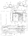
図1は、本発明に係る第一実施形態の製造装置100の概要図である。製造装置100は、チャンバ10と、金属粉末供給装置20と、造形光ビーム照射装置30と、吸収率向上支援部40と、支援光ビーム照射装置41と、造形部70と、を備える。吸収率向上支援部40、及び造形部70は、制御部45に設けられる。また、吸収率向上支援部40は、レーザ光照射制御部49、膜厚推定部50及び処理切替判定部60を備える。
(1-2. Manufacturing apparatus 100)
FIG. 1 is a schematic diagram of a
チャンバ10は、概ね直方体形状で形成された筐体であり、外気と内気との遮断が可能な容器である。チャンバ10は、内部の空気を、例えばHe(ヘリウム)、N2(窒素)やAr(アルゴン)などの不活性ガスに置換可能な装置を備える(不図示)。なお、チャンバ10は、内部を不活性ガスに置換するのではなく、減圧可能な構成としてもよい。
The
金属粉末供給装置20は、チャンバ10の内部に設けられ、三次元造形物の原材料となる金属粉末15を近赤外レーザ光L1(造形光ビームに相当)の照射範囲Ar1(図2参照)に供給する。金属粉末15は銅(Cu)粉末である。なお、ここでいう金属粉末15とは、各銅粉が複数集まった集合体をいう。
The metal
図1、図2に示すように、金属粉末供給装置20は、造形用容器21と、粉末収納容器22とを備える。造形用容器21内には、図1に示すように、造形物昇降テーブル23が設けられる。造形物昇降テーブル23上では、金属粉末15の薄膜層15aが形成される。そして、主に近赤外レーザ光L1の薄膜層15aへの照射によって薄膜層15aの金属粉末15を溶融させ、その後固化させて固化薄膜層15bを形成する。次に、造形物昇降テーブル23を下方に移動させて、上記と同様に、再び薄膜層15aを形成する。そして、主に近赤外レーザ光L1の薄膜層15aへの照射によって薄膜層15aの金属粉末15を溶融させ、その後固化させて固化薄膜層15bを再び形成し、先ほど形成した固化薄膜層15bの上に積層する。このような作業の繰り返しによって三次元造形物が作製される。
As shown in FIGS. 1 and 2, the metal
粉末収納容器22では、フィードテーブル24上に金属粉末15が収納され、フィードテーブル24を上方に移動させることにより、金属粉末15を供給する。なお、造形物昇降テーブル23、フィードテーブル24には、それぞれ支持軸23a、24aが取り付けられる。支持軸23a、24aは、駆動装置(図略)に接続され、駆動装置の作動によって上下に移動される。
In the
また、造形用容器21、及び粉末収納容器22の開口の全領域にわたって移動するリコータ26が設けられる。リコータ26は、図1、図2の右から左に向かって移動する。これにより、フィードテーブル24の上昇により供給された金属粉末15を造形物昇降テーブル23上に運搬するとともに、造形物昇降テーブル23上に金属粉末15の薄膜層15aを形成する。薄膜層15aの厚さは、造形物昇降テーブル23の下降量で決まる。本実施形態では、薄膜層15aの厚さは、50μm〜100μm程度である。ただし、この厚さはあくまで一例を例示したのみであり、この厚さに限定はされない。
Further, a
造形光ビーム照射装置30は、金属粉末供給装置20によって、照射範囲Ar1(図2参照)に供給されたチャンバ10内の金属粉末15の薄膜層15aの表面に近赤外レーザ光L1を照射する。図1に示すように、造形光ビーム照射装置30は、レーザ発振器31、レーザヘッド32を備える。また、レーザ発振器31は、レーザ発振器31から発振された近赤外レーザ光L1をレーザヘッド32に伝送する光ファイバ35を備える。
The modeling light
レーザ発振器31は、波長が予め設定された所定の近赤外波長となるよう発振させて連続波CWのレーザ光である近赤外レーザ光L1を生成する。近赤外レーザ光L1の波長の大きさは、1.0μm前後である。具体的には、近赤外レーザ光L1として、HoYAG(波長:約1.5μm)、YVO(イットリウム・バナデイト、波長:約1.06μm)、Yb(イッテルビウム、波長:約1.09μm)およびファイバーレーザなどが採用可能である。これにより、レーザ発振器31を安価に製作できるとともに、運用時においても消費エネルギーは小さく安価である。なお、材料別のレーザ光の波長(μm)とレーザ光の吸収率(%)との関係を表す図3に示すように、近赤外レーザ光L1は、銅やアルミに対する吸収率が比較的低く、吸収率は30%以下である。
The
図1に示すように、レーザヘッド32は、チャンバ10内の金属粉末15の薄膜層15aの表面から所定の距離を隔て、且つ垂直方向に対して所定の角度α°を有して配置される。
図4に示すように、レーザヘッド32は、コリメートレンズ33、ミラー34、ガルバノスキャナ36、及びfθレンズ38を備える。コリメートレンズ33、ミラー34、ガルバノスキャナ36、及びfθレンズ38は、レーザヘッド32の筐体内に配置される。コリメートレンズ33は、光ファイバ35から出射された近赤外レーザ光L1をコリメートして平行光に変換する。
As shown in FIG. 1, the
As shown in FIG. 4, the
ミラー34は、コリメートされた近赤外レーザ光L1が、ガルバノスキャナ36に入射するよう近赤外レーザ光L1の進行方向を変換する。本実施形態において、ミラー34は、近赤外レーザ光L1の進行方向を90度変換する。
The
ガルバノスキャナ36は、レーザ光Lの進行方向を変更し、近赤外レーザ光L1を、fθレンズ38を介して、薄膜層15aの表面の所定の位置に照射する。つまり、レーザヘッド32は、ガルバノスキャナ36によって、レーザ発振器31から発振された近赤外レーザ光L1の照射角度を自在に変更可能である。なお、近赤外レーザ光L1を照射する所定の位置については、後に詳述する。ガルバノスキャナ36には、例えば、直交する2方向に首ふり運動の可能な一対の可動ミラー(図示しない)を含む周知のスキャナが用いられる。fθレンズ38は、ガルバノスキャナ36から入射された平行なレーザ光Lを集光するレンズである。また、レーザヘッド32から照射されたレーザ光Lは、チャンバ10の上面に設けられる透明なガラス又は樹脂を通してチャンバ10内に照射される。
The
吸収率向上支援部40は、上述した近赤外レーザ光L1(造形光ビーム)及び後述する短波長レーザ光L2(支援光ビーム)を用いて吸収率向上支援処理を実施する制御部であり、制御部45に設けられる(図1参照)。吸収率向上支援部40は、様々な所定の手段(吸収率向上支援処理)をとり得る。しかし、第一実施形態においては、所定の膜厚の酸化膜OMを金属粉末15の薄膜層15aの表面に形成する処理を吸収率向上支援処理とする。
The absorption rate
この処理により、吸収率向上支援処理の後に行なわれる、後述する造形処理において、金属粉末15(銅粉末)に対する近赤外レーザ光L1の吸収率を向上させることができる。なお、近赤外レーザ光L1(造形光ビーム)及び短波長レーザ光L2(支援光ビーム)の照射は、レーザ光照射制御部49によって制御される。
With this process, the absorption rate of the near-infrared laser beam L1 with respect to the metal powder 15 (copper powder) can be improved in a modeling process described later, which is performed after the absorption rate improvement support process. The irradiation of the near-infrared laser beam L1 (modeling light beam) and the short wavelength laser beam L2 (supporting light beam) is controlled by the laser beam
なお、短波長レーザ光の詳細については後述するが、説明の都合上、ここで簡単に説明しておく。短波長レーザ光L2は、近赤外波長より波長が短い短波長(例えば、波長0.2〜0.6μm)のレーザ光である。また、本実施形態において、短波長レーザ光L2は、連続波CWのレーザ光である。材料別のレーザ光の波長(μm)とレーザ光の吸収率(%)との関係を示す図3を見ると、銅に対する短波長レーザ光の吸収率は近赤外レーザ光の吸収率よりも高い。短波長レーザの例として、UVレーザ、グリーンレーザ、及びブルーレーザ等が挙げられる。第一実施形態においては、例えばブルーレーザを適用する。 Although details of the short wavelength laser beam will be described later, for the sake of explanation, a brief description will be given here. The short wavelength laser beam L2 is a laser beam having a short wavelength (for example, a wavelength of 0.2 to 0.6 μm) whose wavelength is shorter than the near infrared wavelength. In the present embodiment, the short wavelength laser beam L2 is a continuous wave CW laser beam. Looking at FIG. 3 showing the relationship between the wavelength (μm) of the laser beam and the absorption rate (%) of the laser beam by material, the absorption rate of the short wavelength laser beam with respect to copper is higher than the absorption rate of the near infrared laser beam. high. Examples of the short wavelength laser include a UV laser, a green laser, and a blue laser. In the first embodiment, for example, a blue laser is applied.
第一実施形態において、吸収率向上支援部40が実施する(制御する)吸収率向上支援処理は、薄膜層15aの表面に対する予熱処理と、予熱処理に引き続いて薄膜層15aの表面に対し行なわれる酸化膜形成処理とである。まず、予熱処理では、金属粉末15(銅粉)に対する吸収率が高い短波長レーザ光L2(支援光ビーム)を、短波長レーザ光照射部46の制御によって薄膜層15aの表面に照射する。この照射により、照射位置であるチャンバ10内における金属粉末15の薄膜層15aの表面を、銅の融点(1060℃)以下である例えば600℃〜800℃まで加熱する。このとき、照射位置における薄膜層15aの表面に酸化膜OMはまだ形成されない。
In the first embodiment, the absorption rate improvement support process performed (controlled) by the absorption rate
図3に示すように、短波長レーザ光L2は、本来、銅に対する吸収率が高いので、低出力でも十分加熱が可能である。これにより、短波長レーザ光L2であっても比較的安価に薄膜層15aの表面の加熱(予熱)ができる。次に、酸化膜形成処理では、薄膜層15aの表面が加熱(予熱)され、ベース温度が上昇した状態で、短波長レーザ光L2及び近赤外レーザ光L1を同時に重畳照射し薄膜層15aの表面に酸化膜OMを形成する。
As shown in FIG. 3, the short-wavelength laser light L2 inherently has a high absorptivity with respect to copper, so that it can be sufficiently heated even at a low output. Thereby, even the short wavelength laser light L2 can heat (preheat) the surface of the
なお、上記において、薄膜層15aの表面を予熱する目的は、酸化膜形成処理において、薄膜層15aの表面に酸化膜OMをより容易に形成可能とするためである。つまり、予熱によって、薄膜層15aのベース温度が上昇する。このため、短波長レーザ光L2及び近赤外レーザ光L1を同時に重畳照射する際、酸化膜OMの形成までに昇温させるべき温度の幅を小さくすることができる。従って、短波長レーザ光L2及び近赤外レーザ光L1の重畳照射時間が短縮でき、短時間、低出力で酸化膜OMの形成が可能となる。
In the above, the purpose of preheating the surface of the
また、銅においては、融点近傍において、近赤外レーザ光L1の吸収率が向上するとともに、照射表面に酸化膜OM(酸化第一銅)が形成されることがわかっている。このため、薄膜層15aの表面を短波長レーザ光L2の照射によって600℃〜800℃に予熱することにより、酸化膜形成処理における短波長レーザ光L2及び近赤外レーザ光L1による重畳照射の照射時間、及び出力(必要エネルギー)を良好に抑制できる。このように、第一実施形態においては、薄膜層15aの表面に、短波長レーザ光L2を照射することによって予熱する予熱処理、及び予熱されて保温状態となっている薄膜層15aの表面に、短波長レーザ光L2及び近赤外レーザ光L1を重畳照射することにより酸化膜OMを形成する酸化膜形成処理が、吸収率向上支援処理となる。
In addition, it is known that in copper, the absorption rate of the near-infrared laser light L1 is improved near the melting point, and an oxide film OM (cuprous oxide) is formed on the irradiated surface. For this reason, the surface of the
ここで、銅に対する近赤外レーザ光L1の吸収率と酸化膜OMの膜厚との関係について説明しておく。図5に示すように、金属粉末15の各銅粉の表面に酸化膜OMが形成されると、酸化膜OMに向かって照射される近赤外レーザ光L1は、酸化膜OMを透過又は酸化膜OM内を反射しながら、銅粉の表面に効率的に吸収され、銅粉を良好に加熱する。なお、銅粉に対して近赤外レーザ光L1の吸収率を向上させる酸化膜OMの作用は、公知の知見に基づくものである。よって、効果を生じさせる原理等の説明は省略する。また、近赤外レーザ光L1の銅粉への吸収率は、図6のグラフに示すように酸化膜OMの膜厚に応じて異なる。
Here, the relationship between the absorption rate of the near-infrared laser beam L1 with respect to copper and the film thickness of the oxide film OM will be described. As shown in FIG. 5, when the oxide film OM is formed on the surface of each copper powder of the
図6のグラフでは、横軸が銅部材の表面に形成した酸化膜OMの膜厚(nm)であり、縦軸が、形成した酸化膜OMを介して近赤外レーザ光L1を銅部材に照射したときにおける銅部材への近赤外レーザ光L1の吸収率(%)である実験データである。この実験では、近赤外レーザ光L1の照射の対象として銅粉を用いず、一辺10mmの角材を用いたが、各銅粉の表面に酸化膜OMを形成したときと、近似の結果が得られると推定して図6の銅部材のデータを採用する。 In the graph of FIG. 6, the horizontal axis represents the film thickness (nm) of the oxide film OM formed on the surface of the copper member, and the vertical axis represents the near-infrared laser light L1 applied to the copper member via the formed oxide film OM. It is an experimental data which is the absorptivity (%) of the near-infrared laser beam L1 to the copper member when irradiated. In this experiment, copper powder was not used as the object of irradiation with the near-infrared laser beam L1, but a square member having a side of 10 mm was used. However, an approximate result was obtained when an oxide film OM was formed on the surface of each copper powder. The data of the copper member in FIG.
図6のグラフを見ると、近赤外レーザ光L1の吸収率は、酸化膜OMの膜厚との関係において、膜厚の増大方向への変化に対して極大値と極小値とが交互に出現する周期性を有している。また、酸化膜OMの膜厚が0のときに、吸収率は最も小さくなっている。これより、発明者は、周期性を有する吸収率との関係において、酸化膜OMの所定の膜厚が、ゼロを超え、はじめに吸収率が極大値として出現する第一極大値aに対応する第一極大膜厚A以下の範囲内となるよう設定することとした。これにより、酸化膜形成後の銅粉の吸収率は、酸化膜が全く形成されていない銅粉の吸収率に対して確実に大きくなる。 As seen from the graph of FIG. 6, the absorption rate of the near-infrared laser beam L1 is alternately a maximum value and a minimum value with respect to a change in the increasing direction of the film thickness in relation to the film thickness of the oxide film OM. It has periodicity that appears. Further, when the thickness of the oxide film OM is 0, the absorption rate is the smallest. Accordingly, the inventor corresponds to the first maximum value a corresponding to the first maximum value a in which the predetermined thickness of the oxide film OM exceeds zero and the absorption rate first appears as a maximum value in relation to the absorption rate having periodicity. It was decided to set it within the range of a maximum film thickness A or less. This ensures that the absorption rate of the copper powder after the oxide film is formed is greater than the absorption rate of the copper powder on which no oxide film is formed.
なお、上記の実験の条件であるが、使用した近赤外レーザ光L1は、YAGレーザによるものであり、連続波CWのレーザ光である。また、酸化膜OMは、加熱炉内で形成した。さらに、酸化膜OMの膜厚は、SERA法(連続電気化学還元法)によって測定した。なお、SERA法とは公知の膜厚測定法である。具体的には、まず、金属表面に電解液をあて、電極から微小電流を流して還元反応を起こさせる。このとき、各物質は、固有の還元電位を持つことから、還元に要した時間を測定することで膜厚が算出できる。また、図6のグラフのデータを適用させる金属粉末15(銅粉末)の各銅粉の粒径は、20μm〜60μmの範囲にあり、平均粒径D50が40μm程度である。また、粒径の測定は、公知のレーザ回折・散乱法による。また、図6のデータは、あくまで近赤外レーザ光L1の吸収率と、酸化膜OMの膜厚との関係の一例を示すものであり、数値等はこれに限定されるものではない。 In addition, although it is the conditions of said experiment, the used near-infrared laser beam L1 is based on a YAG laser, and is a continuous wave CW laser beam. The oxide film OM was formed in a heating furnace. Further, the thickness of the oxide film OM was measured by the SERA method (continuous electrochemical reduction method). The SERA method is a known film thickness measurement method. Specifically, first, an electrolytic solution is applied to the metal surface, and a reductive reaction is caused by flowing a minute current from the electrode. At this time, since each substance has a specific reduction potential, the film thickness can be calculated by measuring the time required for the reduction. Moreover, the particle size of each copper powder of the metal powder 15 (copper powder) to which the data of the graph of FIG. 6 is applied is in the range of 20 μm to 60 μm, and the average particle size D50 is about 40 μm. The particle size is measured by a known laser diffraction / scattering method. Moreover, the data of FIG. 6 shows an example of the relationship between the absorptance of the near-infrared laser beam L1 and the film thickness of the oxide film OM, and the numerical values are not limited to this.
図1に示す支援光ビーム照射装置41は、近赤外レーザ光L1とは異なる波長の支援光ビームを金属粉末15に向かって照射する製造装置100が備える装置である。支援光ビーム照射装置41は、吸収率向上支援部40によって支援光ビームの照射が制御される。前述したように、支援光ビームは、近赤外波長より波長が短い短波長(例えば、波長0.2μm〜0.6μm)の短波長レーザ光L2である。
The assisting light
また、前述したように、短波長レーザ光L2は、図3の材料別のレーザ光の波長(μm)とレーザ光の吸収率(%)との関係に示すように、例えば、銅やアルミに対しては、近赤外波長のレーザ光よりも吸収率が高い。しかし、近赤外波長のレーザ光と較べてその運用コストが高い。そこで、本発明においては、短波長レーザ光L2(支援光ビーム)を、高出力が要求される金属粉末15の溶融のため(造形処理)に用いるのではなく、主に吸収率向上支援処理における図5に示すような酸化膜OM形成のために用いる。
As described above, the short-wavelength laser light L2 is, for example, copper or aluminum as shown in the relationship between the laser light wavelength (μm) and the laser light absorption rate (%) for each material in FIG. On the other hand, the absorptance is higher than near-infrared wavelength laser light. However, its operating cost is higher than that of near-infrared wavelength laser light. Therefore, in the present invention, the short wavelength laser beam L2 (support light beam) is not used for melting the
支援光ビーム照射装置41は、造形光ビーム照射装置30に対し、レーザ発振器43が発振するレーザ光の波長が異なる。また、造形光ビーム照射装置30に対し、ガルバノスキャナを有していない点が異なる。これにより、レーザヘッド42から照射されるレーザ光は一定方向のみである。
The assisting light
また、支援光ビーム照射装置41は、レーザヘッド42が造形光ビーム照射装置30のレーザヘッド32と干渉しないよう垂直方向に対して所定の角度β°を有して配置される。さらに、支援光ビーム照射装置41は、レーザヘッド42が、図略のXYロボットによって移動されることにより、レーザ光の照射位置を制御される。これにより、短波長レーザ光L2の照射位置が、チャンバ10内の金属粉末15の薄膜層15aの表面上をXY軸上で移動可能となっている。なお、本実施形態において、XY平面は、水平面と平行な平面とする。
Further, the assisting light
また、短波長レーザ光L2は、近赤外レーザ光L1のスポット径と比較して、より大きなスポット径での照射が可能である。つまり、短波長レーザ光L2は、スポット径を大きくすることでパワー密度を下げて照射することが可能である。短波長レーザ光L2の照射は、図2に示す照射範囲Ar1内で行なわれ、XYロボットの制御により行なわれる照射位置は、吸収率向上支援部40によって制御される。上記以外は、造形光ビーム照射装置30と同様であるので、詳細な説明及び図については省略する。
Further, the short wavelength laser light L2 can be irradiated with a larger spot diameter as compared with the spot diameter of the near infrared laser light L1. That is, the short wavelength laser beam L2 can be irradiated with a reduced power density by increasing the spot diameter. The irradiation of the short wavelength laser beam L2 is performed within the irradiation range Ar1 shown in FIG. 2, and the irradiation position performed by the control of the XY robot is controlled by the absorptance
吸収率向上支援部40の膜厚推定部50は、吸収率向上支援処理によって薄膜層15aの表面に形成される酸化膜OMの膜厚を推定する。図1に示すように、膜厚推定部50は、表面温度測定部51と、照射時間計測部52と、酸化膜厚演算部53と、を備える。
The film
表面温度測定部51は、酸化膜形成処理時において、薄膜層15aの表面への短波長レーザ光L2及び近赤外レーザ光L1の重畳照射時における薄膜層15aの表面温度Tを測定する。このとき、表面温度Tは、非接触式の赤外線放射温度計39(図1参照)によって測定する。ただし、この態様には限定されず、温度測定は、どのような測定器を用いて行なってもよい。測定された薄膜層15aの表面温度データは、酸化膜厚演算部53に送信される。
The surface
照射時間計測部52は、酸化膜形成処理時において、短波長レーザ光L2及び近赤外レーザ光L1が薄膜層15aの表面に重畳照射された各照射時間Hを計測する。この場合、実際に照射時間Hを計測してもよい。しかし、この態様には限らず、予め設定されている照射時間データを制御部45から取得してもよい。その後、照射時間データは、酸化膜厚演算部53に送信される。
The irradiation
酸化膜厚演算部53は、測定された表面温度Tと計測された照射時間Hとに基づき、酸化膜OMの膜厚を演算し推定する。酸化膜OMの膜厚は、短波長レーザ光L2及び近赤外レーザ光L1の重畳照射によって上昇する薄膜層15aの表面温度Tと重畳照射の照射時間H(照射継続時間)とに応じた厚さで形成される。つまり、酸化膜OMの各膜厚は、表面温度Tと照射時間Hと、によって演算可能である。
The oxide film
吸収率向上支援部40の処理切替判定部60は、酸化膜厚演算部53によって演算された酸化膜OMの膜厚が、所定の膜厚に達したか否かを判定する。そして、処理切替判定部60が、酸化膜OMの膜厚が所定の膜厚に達したと判定した場合に、実施する処理を吸収率向上支援処理から後述する造形部70による造形処理に切替える。
The process switching
なお、本実施形態のように、酸化膜OMの形成箇所が複数ある場合には、処理切替判定部60は、全ての酸化膜OMが形成された後に、実施する処理を吸収率向上支援処理から後述する造形部70による造形処理に切替える。
Note that, when there are a plurality of portions where the oxide film OM is formed as in the present embodiment, the process switching
造形部70は、吸収率向上支援処理の実施後に、制御部45の近赤外レーザ光照射部47によって、造形光ビーム照射装置30を作動させ、近赤外レーザ光L1(造形光ビーム)を薄膜層15aの表面上に形成された所定の膜厚の酸化膜OMに向かって照射する制御部である。
The
なお、この態様に限らず、造形部70は、近赤外レーザ光照射部47及び制御部45の短波長レーザ光照射部46によって、造形光ビーム照射装置30及び支援光ビーム照射装置41を作動させ、近赤外レーザ光L1(造形光ビーム)及び短波長レーザ光L2(支援光ビーム)を酸化膜OMに向かって同時に照射してもよい。
Not limited to this aspect, the
これにより、主に近赤外レーザ光L1が、酸化膜OMの膜厚に応じて薄膜層15aの表層に存在する各銅粉の表面から各銅粉内部に良好に吸収される。このように、造形部70は、薄膜層15aを加熱し、薄膜層15aを溶融させ、後に固化させて造形物を積層造形する造形処理を行なう。
Thereby, mainly the near-infrared laser beam L1 is favorably absorbed into each copper powder from the surface of each copper powder present on the surface layer of the
詳細には、主に近赤外レーザ光L1の照射によって、薄膜層15aにおける表層の各銅粉の温度が銅の融点を超えて上昇し各銅粉は短時間で溶融する。そして、上昇した薄膜層15aの銅粉の熱は、表層の銅粉の下側で表層の各銅粉と接する下層の銅粉の温度も上昇させ溶融させる。このようにして連鎖的に短時間で薄膜層15aが溶融する。その後、溶融した薄膜層15aを冷却することにより、薄膜層15aの下方で既に形成されている固化薄膜層15bとの間で界面が良好に接合されて積層造形される。
Specifically, mainly by irradiation with the near-infrared laser beam L1, the temperature of each surface copper powder in the
(1−3.製造方法)
次に、造形物の製造方法について,図7のフローチャート1に基づき説明する。造形物の製造方法は、金属粉末供給工程S10と、吸収率向上支援工程S20と、造形工程S30と、を備える。なお、吸収率向上支援工程S20は、予熱処理工程S20a、酸化膜形成処理工程S20b、膜厚演算工程S20c、膜厚判定工程S20d及び処理切替判定工程S20eを備える。
(1-3. Manufacturing method)
Next, the manufacturing method of a molded article is demonstrated based on the
まず、準備段階について説明する。はじめに、粉末収納容器22内に、金属粉末15を投入する。次に、製造装置100のチャンバ10内の空気を、図略のガス置換装置によって、例えばHeガスに置換する。このとき、空気は100%置換されなくともよい。空気は、薄膜層15aの表面に、ナノメートル(nm)オーダーの酸化膜OMを形成可能とする酸素を含む空気の分だけチャンバ10内に残留していてもよい。この空気の置換量は、予め実験等により求めておく。
First, the preparation stage will be described. First, the
これにより、造形物が完成したとき、造形物内に残留する酸化物量は最小限となるので、造形された造形物の強度は一定以上に維持される。また、各レーザ光照射時に意図せぬ燃焼が発生することもない。 Thereby, when the modeled object is completed, the amount of oxide remaining in the modeled object is minimized, so that the strength of the modeled modeled object is maintained above a certain level. In addition, unintended combustion does not occur when each laser beam is irradiated.
金属粉末供給工程S10では、制御部45の金属粉末供給制御部25が、金属粉末供給装置20を作動させ、造形物昇降テーブル23上に金属粉末15を供給し、照射範囲Ar1に金属粉末15の薄膜層15aを形成する。このため、金属粉末供給制御部25が、まず、金属粉末15を載せたフィードテーブル24を上昇させるとともに、造形物昇降テーブル23を薄膜層15aの一層分だけ下降させる。
In the metal powder supply step S10, the metal powder
そして、リコータ26を、図1における右から左に向かって移動させて、粉末収納容器22から造形用容器21に金属粉末15を供給し、造形物昇降テーブル23上に粉末の薄膜層15aを形成する。
Then, the
次に、吸収率向上支援工程S20では、吸収率向上支援部40の制御によって、近赤外レーザ光L1(造形光ビーム)の金属粉末15への吸収率を向上させるため、金属粉末15に対して、所定の吸収率向上支援処理を行なう。このとき、吸収率向上支援処理は、上述したように、近赤外レーザ光L1(造形光ビーム)及び短波長レーザ光L2(支援光ビーム)を用いて、薄膜層15aの表面に酸化膜OMを形成する処理である。
Next, in the absorptance improvement support process S20, in order to improve the absorptance to the
具体的には、予熱処理工程S20a(吸収率向上支援工程S20)は、短波長レーザ光L2の照射による予熱のための予熱処理を行なう。予熱処理工程S20aでは、吸収率向上支援部40が備えるレーザ光照射制御部49が、短波長レーザ光照射部46を制御し、まず支援光ビーム照射装置41を作動させる。
Specifically, the pre-heat treatment step S20a (absorption rate improvement support step S20) performs pre-heat treatment for pre-heating by irradiation with the short wavelength laser beam L2. In the pre-heat treatment step S20a, the laser light
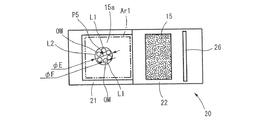
これにより、図8Aに示すように、照射範囲Ar1内における薄膜層15aの表面の第五照射位置P5に、短波長レーザ光L2(支援光ビーム)を第五スポット径φEで照射し、予熱処理を実施する。第五スポット径φEは、比較的大きな径である。このため、第五照射位置P5では、短波長レーザ光L2が本来照射可能なパワー密度より小さなパワー密度で照射される。そして、短波長レーザ光L2は、第五照射位置P5が例えば600℃〜800℃になるよう加熱する。
As a result, as shown in FIG. 8A, the fifth irradiation position P5 on the surface of the
第五照射位置P5の表面温度Tは、例えば、非接触式の赤外線放射温度計39(図1参照)によって監視すればよい。そして、第五照射位置P5の温度が、例えば600℃〜800℃になったことを確認したら、予熱処理を停止する。 What is necessary is just to monitor the surface temperature T of the 5th irradiation position P5 with the non-contact-type infrared radiation thermometer 39 (refer FIG. 1), for example. And if it confirms that the temperature of the 5th irradiation position P5 will be 600 to 800 degreeC, for example, pre-heat processing will be stopped.
次に、酸化膜形成処理工程S20b(吸収率向上支援工程S20)にて、レーザ光照射制御部49が、短波長レーザ光照射部46及び近赤外レーザ光照射部47を制御し、支援光ビーム照射装置41及び造形光ビーム照射装置30を同時に作動させる。これにより、図8Bに示すように、短波長レーザ光L2及び近赤外レーザ光L1を、予熱処理され保温されている薄膜層15aの表面に重畳して照射する。
Next, in the oxide film formation processing step S20b (absorption rate improvement support step S20), the laser beam
なお、このとき、短波長レーザ光L2の照射位置及び照射スポット径は、予熱処理時における照射スポット径と同じである(第五照射位置P5、第五スポット径φE)。よって、短波長レーザ光L2は、予熱処理からそのまま継続して照射し続けてもよい。 At this time, the irradiation position and irradiation spot diameter of the short wavelength laser beam L2 are the same as the irradiation spot diameter at the time of the pre-heat treatment (fifth irradiation position P5, fifth spot diameter φE). Therefore, the short wavelength laser beam L2 may be continuously irradiated from the pre-heat treatment.
また、近赤外レーザ光L1の照射のスポット径である第六スポット径φF(第四スポット径φDにも相当)は、第五スポット径φE(第三スポット径φCにも相当)よりも小さな径である。そして、近赤外レーザ光L1は、短波長レーザ光L2の照射範囲である第五スポット径φEの範囲内の所定の位置に重畳照射される。 Further, the sixth spot diameter φF (corresponding to the fourth spot diameter φD), which is the spot diameter of the irradiation with the near-infrared laser beam L1, is smaller than the fifth spot diameter φE (corresponding to the third spot diameter φC). Is the diameter. The near-infrared laser beam L1 is superimposed and applied to a predetermined position within the range of the fifth spot diameter φE, which is the irradiation range of the short wavelength laser beam L2.
このとき、所定の位置とは、これから作製すべき三次元造形物のスライスデータ(描画パターン)に基づく位置であり、三次元造形物を形成させたい位置である。なお、短波長レーザ光L2が照射される照射位置である第五照射位置P5も、作製すべき三次元造形物のスライスデータ(描画パターン)に基づき設定されていることはいうまでもない。 At this time, the predetermined position is a position based on slice data (drawing pattern) of a three-dimensional structure to be produced from now on, and is a position where a three-dimensional structure is desired to be formed. Needless to say, the fifth irradiation position P5, which is the irradiation position irradiated with the short-wavelength laser light L2, is also set based on slice data (drawing pattern) of the three-dimensional structure to be manufactured.
そして、近赤外レーザ光L1が短波長レーザ光L2に重畳照射される薄膜層15aの表面上の位置において、照射位置の表面温度Tが、銅の融点近傍に近づくと酸化膜OMが形成され始める。
Then, at the position on the surface of the
次に、膜厚演算工程S20c(吸収率向上支援工程S20)では、膜厚推定部50によって、薄膜層15aの表面に形成される酸化膜OMの膜厚tを演算する。
膜厚判定工程S20d(吸収率向上支援工程S20)では、膜厚演算工程S20cで演算した酸化膜OMの膜厚tが、所定の膜厚の範囲内に入っているか否かが、処理切替判定部60によって判定される。
Next, in the film thickness calculation step S20c (absorption rate improvement support step S20), the film
In the film thickness determination step S20d (absorption rate improvement support step S20), it is determined whether or not the film thickness t of the oxide film OM calculated in the film thickness calculation step S20c is within a predetermined film thickness range. Determined by the
演算された酸化膜OMの膜厚tが、所定の膜厚の範囲内である、0を超え、且つA(nm)以下の範囲である、B(nm)〜A(nm)内に入っていれば、当該位置における近赤外レーザ光L1の照射を停止し、処理切替判定工程S20eに移動する。しかし、膜厚tが、B(nm)〜A(nm)の範囲内に入っていなければ、膜厚演算工程S20cに移動し、膜厚tが、B(nm)〜A(nm)の範囲内に入るまで、S20c及びS20dを繰り返し処理する。 The calculated thickness t of the oxide film OM is within the range of a predetermined thickness, which is in the range of B (nm) to A (nm), which is greater than 0 and less than or equal to A (nm). Then, the irradiation of the near-infrared laser beam L1 at the position is stopped, and the process proceeds to the process switching determination step S20e. However, if the film thickness t is not within the range of B (nm) to A (nm), the process moves to the film thickness calculation step S20c, and the film thickness t is within the range of B (nm) to A (nm). Until it enters, S20c and S20d are repeatedly processed.
なお、B(nm)〜A(nm)は、図6のグラフにおいて、吸収率b%〜a%に対応する膜厚である。また、所定の膜厚の範囲は、0を超え、且つA(nm)以下の範囲内であれば、どのような範囲で設定してもよい。なお、このとき、一例として、所定の膜厚(B(nm)〜A(nm))を、図6のグラフに示すように吸収率10%(b%)〜60%(a%)に対応する5nm〜85nmとしてもよい。ただし、この設定膜厚はあくまで一例を示したものであって、数値は任意に変更可能である。また、A(nm)の値も、85nmに限るものではない。また、酸化膜OMは、図5に示すように、金属粉末15の各銅粉の最表面に形成される。
B (nm) to A (nm) are film thicknesses corresponding to the absorptances b% to a% in the graph of FIG. Further, the predetermined film thickness range may be set in any range as long as it is in the range of more than 0 and not more than A (nm). At this time, as an example, a predetermined film thickness (B (nm) to A (nm)) corresponds to an absorption rate of 10% (b%) to 60% (a%) as shown in the graph of FIG. It may be 5 nm to 85 nm. However, the set film thickness is merely an example, and the numerical value can be arbitrarily changed. Further, the value of A (nm) is not limited to 85 nm. The oxide film OM is formed on the outermost surface of each copper powder of the
処理切替判定工程S20e(吸収率向上支援工程S20)では、処理切替判定部60が、薄膜層15aにおいて形成されるべき複数の酸化膜OMの全てが形成されてはおらず、形成されるべき酸化膜OMがまだ残っていると判定したら、酸化膜形成処理工程S20bに戻り、近赤外レーザ光L1の照射位置を短波長レーザ光L2の照射範囲内において変更し、次の酸化膜OMの形成処理を行なう。このような処理を繰り返し行ない、造形物を形成するため必要な酸化膜OMを照射範囲Ar1内において複数(全箇所)形成する(図8C参照)。
In the processing switching determination step S20e (absorption rate improvement support step S20), the processing
しかし、処理切替判定工程S20eにおいて、処理切替判定部60が、形成されるべき酸化膜OMは全箇所形成された、と判定したら、処理を酸化膜形成処理から造形処理に切り替え、造形工程S30に移動する。このように、本実施形態においては、短波長レーザ光L2と近赤外レーザ光L1との重畳照射によって、形成すべき全ての酸化膜OMが、所定の膜厚に達した状態で形成されたと判定された場合に、吸収率向上支援処理から造形処理に切替える。このようにして、造形物を形成するため必要な酸化膜OMを第五スポット径φEの範囲内において第五スポット径φEより小さな第六スポット径φFで複数形成する(図8C参照)。
However, in the process switching determination step S20e, when the process switching
なお、上記の膜厚演算工程S20cにおいて演算される酸化膜OMの膜厚は、上述したように膜厚推定部50(表面温度測定部51、照射時間計測部52、及び酸化膜厚演算部53)によって推定する。膜厚推定部50の作動については、前述したとおりであるので、詳細な説明については省略する。
The film thickness of the oxide film OM calculated in the film thickness calculation step S20c is the film thickness estimation unit 50 (surface
造形工程S30(造形処理)では、制御部45が備える造形部70が、造形光ビーム照射装置30を作動させ、図8Dに示すように、近赤外レーザ光L1(造形光ビーム)を、薄膜層15aの表面の各酸化膜OMの形成位置に第六スポット径φFでそれぞれ照射する。このため、近赤外レーザ光L1は、酸化膜OMが形成されたことにより近赤外レーザ光L1の吸収率が向上した金属粉末15を良好に加熱する。
In modeling process S30 (modeling process), modeling
そして、金属粉末15を短時間で溶融させた後、固化させ薄膜層15aを固化薄膜層15bとして形成し積層造形する。図8Eに示すように、全ての酸化膜OMの形成位置における薄膜層15aを固化薄膜層15bとして形成し終えたら、S10に戻る。そして、金属粉末供給装置20による次の薄膜層15aの形成から再度開始する。
Then, after melting the
なお、上記においては、吸収率向上支援工程S20において、短波長レーザ光L2と近赤外レーザ光L1との重畳照射によって所定の膜厚の酸化膜OMを複数箇所形成したのち、造形工程S30に移動した。そして、造形工程S30において、近赤外レーザ光L1を照射して固化薄膜層15bを形成し造形物を積層造形した。
In the above, in the absorption rate improvement support step S20, a plurality of oxide films OM having a predetermined film thickness are formed by overlapping irradiation with the short wavelength laser light L2 and the near infrared laser light L1, and then the forming step S30 is performed. moved. And in modeling process S30, the near-infrared laser beam L1 was irradiated, the solidified
しかし、この態様には限らない。吸収率向上支援工程S20において、短波長レーザ光L2と近赤外レーザ光L1との重畳照射によって所定の膜厚の酸化膜OMを1箇所形成したのち、膜厚判定工程S20d及び処理切替判定工程S20eの判定によって造形工程S30に移動し、近赤外レーザ光L1を照射して固化薄膜層15bを形成し造形物を積層造形してもよい。この場合、吸収率向上支援工程S20と造形工程S30との間を複数回往復することで、複数個の固化薄膜層15bが形成される。
However, it is not limited to this aspect. In the absorptance improvement support step S20, an oxide film OM having a predetermined film thickness is formed by overlapping irradiation with the short wavelength laser beam L2 and the near-infrared laser beam L1, and then a film thickness determination step S20d and a process switching determination step. It moves to modeling process S30 by determination of S20e, may irradiate near infrared laser beam L1, may form the solidified
(1−4.第一実施形態の変形態様)
上記第一実施形態においては、造形工程S30において、近赤外レーザ光L1(造形光ビーム)のみの照射によって、固化薄膜層15bを形成して積層造形した。しかしこの態様には限らない。第一実施形態の変形態様として、造形工程S30においては、吸収率向上支援工程S20における短波長レーザ光L2の照射を停止させず、図8Bと同様に、近赤外レーザ光L1を短波長レーザ光L2に重畳して照射してもよい。これにより、第一実施形態に対し、より多くのエネルギーは消費するが、短波長レーザ光L2のエネルギー分だけより短時間で固化薄膜層15bが形成できる。
(1-4. Modification of First Embodiment)
In the first embodiment, in the modeling step S30, the solidified
(1−5.第一実施形態の変形例1)
また、上記第一実施形態では、予熱処理工程S20a(吸収率向上支援工程S20)において、薄膜層15aの表面に対し予熱処理を行なう際、短波長レーザ光L2のみの照射によって行なった。しかし、この態様には限らない。第一実施形態の変形例1として、予熱処理工程S20aにおいて予熱処理を行なう際、図8Bと同様に、短波長レーザ光L2に加え、近赤外レーザ光L1を重畳して照射してもよい。この場合、近赤外レーザ光L1の照射範囲は短波長レーザ光L2の照射範囲よりも狭いが、第一実施形態より早い薄膜層15aの予熱処理の完了が期待できる。
(1-5.
In the first embodiment, in the pre-heat treatment step S20a (absorption rate improvement support step S20), when the pre-heat treatment is performed on the surface of the
(1−6.第一実施形態の変形例2)
また、上記第一実施形態の変形態様においても、予熱処理を行なう際、第一実施形態の変形例1と同様、図8Bに示すように、短波長レーザ光L2に加え、近赤外レーザ光L1を重畳して照射してもよい。この態様を、第一実施形態の変形例2とする。この場合においても、第一実施形態の変形態様に対して、より早い薄膜層15aの予熱の完了が期待できる。
(1-6. Modification 2 of First Embodiment)
Also, in the modified embodiment of the first embodiment, when performing the pre-heat treatment, as shown in FIG. 8B, as in the modified example 1 of the first embodiment, the near-infrared laser beam is added in addition to the short wavelength laser beam L2. L1 may be superimposed and irradiated. This aspect is referred to as a second modification of the first embodiment. Even in this case, it can be expected that the preheating of the
<2.第二実施形態>
(2−1. 製造装置200)
次に、第二実施形態について説明する。図1に示す第二実施形態の製造装置200は、第一実施形態の製造装置100に対して、吸収率向上支援部40の吸収率向上支援処理が、予熱処理を有さない点が異なる。また、製造装置200は、第一実施形態の製造装置100に対して、吸収率向上支援処理における酸化膜OMを形成する処理(酸化膜形成処理)が一部異なる。
<2. Second embodiment>
(2-1. Manufacturing apparatus 200)
Next, a second embodiment will be described. The
具体的には、第一実施形態の製造装置100では、酸化膜形成処理において、短波長レーザ光L2(支援光ビーム)を金属粉末15の照射範囲Ar1内における第五照射位置P5に第五スポット径φEで照射すると同時に、近赤外レーザ光L1(造形光ビーム)を第五スポット径φEより径の小さな第六スポット径φFで短波長レーザ光L2(支援光ビーム)に重畳して照射することで、酸化膜OMを形成した。
Specifically, in the
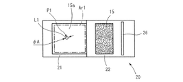
しかし、第二実施形態の製造装置200では、図9Aに示すように、酸化膜形成処理において、短波長レーザ光L2(支援光ビーム)を金属粉末15の照射範囲Ar1内における第一照射位置P1に第一スポット径φAで照射するのと同時に、近赤外レーザ光L1(造形光ビーム)を第一照射位置P1に第一スポット径φAで短波長レーザ光L2(支援光ビーム)に重畳して照射することで、酸化膜OMを形成する。
However, in the
つまり、短波長レーザ光L2、及び近赤外レーザ光L1の各照射スポット径が同じであり、第一実施形態とは、この点が大きく異なる。そして、造形部70は、図9Bに示すように、近赤外レーザ光L1(造形光ビーム)を第一スポット径φAで酸化膜OMの形成位置である第一照射位置P1に照射して造形処理を実施(制御)する。造形部70による造形処理は、第一実施形態と同様である。
That is, the irradiation spot diameters of the short wavelength laser beam L2 and the near infrared laser beam L1 are the same, which is greatly different from the first embodiment. Then, as shown in FIG. 9B, the
上記第二実施形態によれば、造形物の製造装置200において、吸収率向上支援処理は、金属粉末15の表面に酸化膜OMを形成する処理であり、吸収率向上支援部40は、短波長レーザ光L2(支援光ビーム)を金属粉末15の照射範囲Ar1内における第一照射位置P1に第一スポット径φAで照射すると同時に、近赤外レーザ光L1(造形光ビーム)を第一照射位置P1に第一スポット径φAで短波長レーザ光L2(支援光ビーム)に重畳して照射することで、酸化膜OMを形成する。
According to the second embodiment, in the molded
これにより、予熱処理がなくとも、吸収率向上支援処理では、同じ径で照射されるパワー密度の高い短波長レーザ光L2、及び近赤外レーザ光L1の重畳照射により出力が上昇し、短時間で酸化膜OMの形成が可能となり、効率的である。 As a result, even if there is no pre-heat treatment, in the absorption rate improvement support process, the output increases due to the superimposed irradiation of the short-wavelength laser light L2 and the near-infrared laser light L1, which are irradiated with the same diameter and have a high power density. Thus, the oxide film OM can be formed, which is efficient.
(2−2.第二実施形態の変形態様)
上記第二実施形態では、造形処理を行なう際、第一実施形態と同様に、近赤外レーザ光L1のみの照射で実施した。しかしこの態様には限らない。造形処理は、吸収率向上支援処理(酸化膜形成処理)と同様、図9Aと同様、短波長レーザ光L2(支援光ビーム)を、金属粉末15の照射範囲Ar1内における第一照射位置P1に第一スポット径φAで照射すると同時に、近赤外レーザ光L1(造形光ビーム)を第一照射位置P1に第一スポット径φAで短波長レーザ光L2(支援光ビーム)に重畳して照射してもよい。これにより、コストは高くなるが、造形処理は、短時間で完了できる。
(2-2. Modification of Second Embodiment)
In said 2nd embodiment, when performing modeling process, it implemented by irradiation of only the near-infrared laser beam L1, similarly to 1st embodiment. However, it is not limited to this aspect. Similar to FIG. 9A, the modeling processing is performed at the first irradiation position P1 in the irradiation range Ar1 of the
(2−3.第二実施形態の変形例1)
また、上記第二実施形態では、吸収率向上支援処理(酸化膜形成処理)を行なう際、短波長レーザ光L2(支援光ビーム)を金属粉末15の照射範囲Ar1内における第一照射位置P1に第一スポット径φAで照射すると同時に、近赤外レーザ光L1(造形光ビーム)を第一照射位置P1に第一スポット径φAで短波長レーザ光L2(支援光ビーム)に重畳して照射した。また、造形部70では、近赤外レーザ光L1(造形光ビーム)を第一スポット径φAで酸化膜OMの形成位置である第一照射位置P1に照射して造形処理を実施した。
(2-3.
In the second embodiment, the short wavelength laser beam L2 (supporting light beam) is applied to the first irradiation position P1 within the irradiation range Ar1 of the
しかし、この態様には限らない。第二実施形態の変形例1として、吸収率向上支援部40は、図10に示すように、短波長レーザ光L2(支援光ビーム)を金属粉末15の照射範囲Ar1内における第三照射位置P3に第三スポット径φCで照射すると同時に、近赤外レーザ光L1(造形光ビーム)を第三スポット径φCより径の小さな第四スポット径φDで短波長レーザ光L2(支援光ビーム)に重畳して照射することで、酸化膜OMを形成してもよい。つまり、吸収率向上支援部40は、広範囲に照射した短波長レーザ光L2に、狭い範囲の近赤外レーザ光L1を重畳して照射してもよい。これにより、短波長レーザ光L2の照射については、酸化膜形成に寄与しながら大きなコストはかからない。
However, it is not limited to this aspect. As
(2−4.第二実施形態の変形例2)
また、第二実施形態の変形例2として、第二実施形態の変形例1に対し造形部70のみ変更してもよい。具体的には、造形部70は、第二実施形態の変形例1の吸収率向上支援部40と同様に、図10に示すように、短波長レーザ光L2(支援光ビーム)を、金属粉末15の照射範囲Ar1内における第三照射位置P3に第三スポット径φCで照射するのと同時に、近赤外レーザ光L1(造形光ビーム)を第三スポット径φCより径の小さな第四スポット径φDで短波長レーザ光L2(支援光ビーム)に重畳して照射することで造形処理を実施してもよい。つまり、造形部70は、広範囲に照射した短波長レーザ光L2に、狭い範囲の近赤外レーザ光L1を重畳して照射してもよい。これにより、短波長レーザ光L2の照射については、加熱に寄与しながら大きなコストはかからない。
(2-4. Modification 2 of Second Embodiment)
As modification 2 of the second embodiment, only the
<3.第三実施形態>
(3−1. 製造装置300)
次に、第三実施形態について図11に基づき説明する。第三実施形態の製造装置300は、第一実施形態の製造装置100に対して、造形光ビーム照射装置30が異なる。具体的には、造形光ビーム照射装置30と支援光ビーム照射装置41とが一体となって、造形光及び支援光ビーム照射装置130を構成する。つまり、製造装置300は、1台の造形光及び支援光ビーム照射装置130によって、近赤外レーザ光L1(造形光ビーム)と短波長レーザ光L2(支援光ビーム)との切替え照射が可能な構成である。よって、造形光及び支援光ビーム照射装置130は、支援光ビーム照射装置41を備えているといえる。
<3. Third Embodiment>
(3-1. Manufacturing apparatus 300)
Next, a third embodiment will be described based on FIG. The
つまり、製造装置300は、チャンバ10と、金属粉末供給装置20と、造形光及び支援光ビーム照射装置130と、吸収率向上支援部140(膜厚推定部50及び処理切替判定部60)と、造形部70と、を備える。吸収率向上支援部140及び造形部70は、制御部45に対応する制御部145に設けられる。よって、第一実施形態の製造装置100に対して、異なる点のみ説明し、同様部分については、説明を省略する。また、同様の構成には、同じ符号を付して説明する場合がある。
That is, the
造形光及び支援光ビーム照射装置130は、金属粉末供給装置20によって、照射範囲Ar1に、供給されたチャンバ10内の金属粉末15の薄膜層15aの表面に近赤外レーザ光L1(造形光ビーム)又は短波長レーザ光L2(支援光ビーム)を照射する。近赤外レーザ光L1及び短波長レーザ光L2は、制御部145が備えるレーザ切替部48の制御によって切替えられる。造形光及び支援光ビーム照射装置130は、レーザ発振器131、及びレーザヘッド132を備える。また、レーザ発振器131は、レーザ発振器131から発振された近赤外レーザ光L1及び短波長レーザ光L2をレーザヘッド132に伝送する光ファイバ135を備える。
The modeling light and assisting light
レーザヘッド132は、図11に示すように、チャンバ10内の金属粉末15の薄膜層15aの表面から所定の距離を隔て、軸線が垂直となるよう配置される。レーザヘッド132は、レーザヘッド32と同様の構成であるため、説明を省略する。吸収率向上支援部140は、短波長レーザ光L2(支援光ビーム)を用いて吸収率向上支援処理を実施する制御部である。
As shown in FIG. 11, the
(3−2.製造方法)
次に、近赤外レーザ光L1(造形光ビーム)を用いて造形物を積層造形する製造方法について,図12のフローチャート2に基づき説明する。造形物の製造方法は、金属粉末供給工程S10と、吸収率向上支援工程S120と、造形工程S130と、を備える。金属粉末供給工程S10については、変更はないので説明を省略する。
(3-2. Manufacturing method)
Next, a manufacturing method for layered modeling of a model using the near infrared laser beam L1 (modeling light beam) will be described based on the flowchart 2 in FIG. The manufacturing method of a molded article includes a metal powder supply step S10, an absorption rate improvement support step S120, and a modeling step S130. Since there is no change about metal powder supply process S10, description is abbreviate | omitted.
吸収率向上支援工程S120では、吸収率向上支援部140の制御によって、近赤外レーザ光L1(造形光ビーム)の金属粉末15への吸収率を向上させるため、金属粉末15に対して、所定の吸収率向上支援処理を行なう。吸収率向上支援工程S120は、酸化膜形成処理工程S120a、膜厚演算工程S120b、膜厚判定工程120c及び処理切替判定工程S120dを備える。
In the absorptance improvement support step S120, the control of the absorptance
酸化膜形成処理工程S120a(吸収率向上支援工程S120)は、短波長レーザ光L2(支援光ビーム)のみの照射によって酸化膜OMを形成する(酸化膜形成処理)。このため、酸化膜形成処理工程S120aでは、レーザ光照射制御部49がレーザ切替部48を制御し、短波長レーザ光照射部46を作動させる。これにより、短波長レーザ光照射部46が、造形光及び支援光ビーム照射装置130を作動させ、短波長レーザ光L2を薄膜層15aの表面に照射する。
In the oxide film formation processing step S120a (absorption rate improvement support step S120), the oxide film OM is formed by irradiation with only the short wavelength laser beam L2 (support light beam) (oxide film formation processing). For this reason, in the oxide film formation processing step S120a, the laser beam
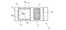
短波長レーザ光L2(支援光ビーム)は、図13Aに示すように、照射範囲Ar1内における薄膜層15aの表面の第二照射位置P2に、第二スポット径φBで照射し酸化膜OMを形成する。このとき、第二スポット径φBは、短波長レーザ光L2が単独で薄膜層15aの表面に酸化膜OMを形成可能とする比較的小さなスポット径である。つまり、短波長レーザ光L2は、パワー密度が大きなレーザ光である。そして、短波長レーザ光L2(支援光ビーム)が照射される位置において、表面温度Tが、銅の融点近傍に近づくと酸化膜OMが形成され始める。
As shown in FIG. 13A, the short-wavelength laser light L2 (supporting light beam) is irradiated at the second irradiation position P2 on the surface of the
膜厚演算工程S120b(吸収率向上支援工程S120)では、膜厚推定部50によって、薄膜層15aの表面に形成される酸化膜OMの膜厚tを演算する。
膜厚判定工程120c(吸収率向上支援工程S120)では、膜厚演算工程S120bで演算した酸化膜OMの膜厚tが、所定の膜厚の範囲内に入っているか否かが、処理切替判定部60によって判定される。
In the film thickness calculation step S120b (absorption rate improvement support step S120), the film
In the film thickness determination step 120c (absorption rate improvement support step S120), it is determined whether or not the film thickness t of the oxide film OM calculated in the film thickness calculation step S120b is within a predetermined film thickness range. Determined by the
演算された酸化膜OMの膜厚tが、所定の膜厚の範囲内である例えば、B(nm)〜A(nm)内に入っていれば、当該位置における近赤外レーザ光L1の照射を停止し、処理切替判定工程S120dに移動する。しかし、膜厚tが、B(nm)〜A(nm)の範囲内に入っていなければ、膜厚演算工程S120bに移動し、膜厚tが、B(nm)〜A(nm)の範囲内に入るまで、S120b及びS120cを繰り返し処理する。 If the calculated film thickness t of the oxide film OM is within a predetermined film thickness range, for example, within the range of B (nm) to A (nm), the near-infrared laser beam L1 is irradiated at that position. Is stopped, and the process proceeds to the process switching determination step S120d. However, if the film thickness t is not within the range of B (nm) to A (nm), the process moves to the film thickness calculation step S120b, and the film thickness t is within the range of B (nm) to A (nm). Until it enters, S120b and S120c are repeatedly processed.
処理切替判定工程S120d(吸収率向上支援工程S120)では、処理切替判定部60が、薄膜層15aにおいて形成されるべき複数の酸化膜OMの全て(全箇所)が形成されてはおらず、形成されるべき酸化膜OMがまだ残っていると判定したら、酸化膜形成処理工程S120aに戻り、短波長レーザ光L2の照射位置を変更し、形成されていない次の酸化膜OMの形成処理を行なう。そして、このような処理を繰り返し行ない、造形物を形成するために必要な複数の酸化膜OMを照射範囲Ar1内において全て形成する(図13B参照)。
In the process switching determination step S120d (absorption rate improvement support process S120), the process switching
しかし、処理切替判定工程S120dにおいて、形成されるべき酸化膜OMが全箇所形成されていると判定されると、処理切替判定部60は,処理を酸化膜形成処理から造形処理に切り替え、造形工程S130に移動させる。このように、本実施形態においては、短波長レーザ光L2の照射によって、形成すべき全ての酸化膜OMが、所定の膜厚に達した状態で形成されたと判定された場合に、吸収率向上支援処理から造形処理に切替える。
However, when it is determined in the process switching determination step S120d that all the oxide films OM to be formed are formed, the process switching
造形工程S130では、制御部145が備える造形部70が、レーザ切替部48を制御し、造形光及び支援光ビーム照射装置130を作動させる。これにより、近赤外レーザ光L1(造形光ビーム)を、図13Cの実線の円で示すように、薄膜層15aの表面の各酸化膜OMの形成位置に第二スポット径φBで照射する。
In the modeling step S130, the
従って、近赤外レーザ光L1は、酸化膜OMの形成により近赤外レーザ光L1の吸収率が向上した金属粉末15を良好に加熱し、短時間で溶融させて固化させ薄膜層15aを固化薄膜層15bとして形成し造形物を積層造形する。そして、図13Cの二点鎖線の円で示す全ての酸化膜OMの形成位置における薄膜層15aを固化薄膜層15bとして形成し終えたら、S10に戻る。そして、金属粉末供給装置20による次の薄膜層15aの形成から再度開始する。
Therefore, the near-infrared laser beam L1 heats the
このように、第三実施形態においては、近赤外レーザ光L1(造形光ビーム)及び短波長レーザ光L2(支援光ビーム)を、一つの造形光及び支援光ビーム照射装置130を備えるだけで実施できるので安価に製造できる。
As described above, in the third embodiment, the near-infrared laser beam L1 (modeling light beam) and the short wavelength laser beam L2 (supporting light beam) are simply provided with one modeling light and supporting light
<4.第四実施形態>
(4−1. 製造装置400)
なお、本発明は、第四実施形態として、上記第一〜第三実施形態の製造装置100〜300とは異なる構成を有する特開2007−216235号公報に開示されるタイプの製造装置400にも適用できる(図14参照)。製造装置400は、上記第一〜第三実施形態の製造装置100〜300と、金属粉末供給装置20、造形光ビーム照射装置30、及び造形光及び支援光ビーム照射装置130が異なる。その中でも特に、金属粉末供給装置20の態様が異なる。
<4. Fourth Embodiment>
(4-1. Manufacturing device 400)
Note that the present invention also includes a
製造装置400は、近赤外レーザ光L1(造形光ビーム)及び短波長レーザ光L2(支援光ビーム)を、レーザ切替部48の制御によって一つの造形光及び支援光ビーム照射装置230を切替えながら照射する。よって、製造装置400は、第三実施形態と同様、支援光ビーム照射装置41を備えているといえる。
The
また、これに加え、製造装置400は、金属粉末供給装置20に対応する金属粉末供給装置220を、レーザ光を出射するレーザヘッド232の外周側に一体的に備える。さらに、製造装置400においては、金属粉末供給装置220及びレーザヘッド232はチャンバ210内に配置される。なお、このようなタイプの製造装置は公知であるので、詳細な説明については省略する。
In addition, the
これにより、製造装置400は、金属粉末15をレーザヘッド232の外周部から金属粉末供給装置220によって照射範囲Ar1内に噴射後、造形光及び支援光ビーム照射装置230から照射する短波長レーザ光L2(支援光ビーム)の照射によって酸化膜形成処理(吸収率向上支援処理)を行ない、薄膜層15aの表面に酸化膜OM(図14では図略)を形成する。そして、酸化膜OMの形成後、制御部145のレーザ切替部48が、造形光及び支援光ビーム照射装置230のレーザ照射を短波長レーザ光L2から近赤外レーザ光L1(造形光ビーム)に切替える。
Thereby, the
これにより、造形光及び支援光ビーム照射装置230から近赤外レーザ光L1を酸化膜OMの形成位置に照射して、造形処理を行ない、三次元造形物を形成する。なお、吸収率向上支援工程及び造形工程は、第二実施形態の吸収率向上支援工程S120及び造形工程S130と同様である。これにより、製造装置400によっても、第三実施形態の製造装置300で製造する造形物と同様の三次元造形物が形成される。
Thereby, the formation position of the oxide film OM is irradiated from the modeling light and assisting light
<5.第五実施形態>
(5−1. 製造装置500)
次に、第五実施形態について図15に基づき説明する。図15に示す第五実施形態の製造装置500は、第一実施形態の製造装置100に対し、支援光ビーム照射装置41を有していない。つまり、製造装置500は、造形光ビーム照射装置30によって、近赤外レーザ光L1(造形光ビーム)のみが照射される装置である。以降においては、主に第一実施形態の製造装置100に対して異なる点のみ説明し、同様部分については、説明を省略する。また、同様の構成には、同じ符号を付して説明する場合がある。
<5. Fifth embodiment>
(5-1. Manufacturing apparatus 500)
Next, a fifth embodiment will be described with reference to FIG. The
製造装置500は、チャンバ10と、金属粉末供給装置20と、造形光ビーム照射装置30と、黒色皮膜形成装置250と、第一実施形態の制御部45に対応する制御部245と、を備える。制御部245は、金属粉末供給制御部25と、吸収率向上支援部240と、近赤外レーザ光照射部47と、造形部70と、を備える。
The
吸収率向上支援部240は、照射範囲Ar1に供給される金属粉末15の表面に対して所定の吸収率向上支援処理を行なう。ここで、所定の吸収率向上支援処理とは、金属粉末15が照射範囲Ar1に供給された後に、金属粉末15の表面に後述する黒色材料を付着させて黒色皮膜BMを形成する処理である。
The absorption rate
黒色皮膜形成装置250は、チャンバ10内に設けられる。黒色皮膜形成装置250は、制御部245が備える吸収率向上支援部240によって制御される。黒色皮膜形成装置250は、金属粉末供給装置20によって照射範囲Ar1に供給された後の金属粉末15の薄膜層15aの表面に、所定の吸収率向上支援処理として、黒色材料の一例であるカーボンブラックCBを噴射して付着させる。
The black
黒色皮膜形成装置250は、貯留容器(図略)内に貯留したカーボンブラックCB(黒色材料)を、薄膜層15aの表面全面に噴射し吹きつけ可能であれば、どのような構成を有して形成されていてもよい。なお、カーボンブラックCBとは、工業的に品質制御して製造される炭素の微粒子であり、インキ、タイヤ等多くの分野で利用されている公知の材料であり、これ以上の詳細な説明については、省略する。カーボンブラックCBは、照射範囲Ar1に供給された金属粉末15(銅粉)の薄膜層15aの表面に薄く付着して、黒色皮膜BMを形成する。
The black
なお、本実施形態において、黒色材料とは、その名のとおり黒色で形成された材料であり、近赤外レーザ光L1(造形光ビーム)の吸収率が高い材料である。黒色材料の例としては、カーボンブラックCB以外に、黒鉛、炭、黒色塗料(黒色インキ)等が挙げられる。黒色材料において、黒色の定義は、厳密ではなく、上述した黒鉛、炭、黒色塗料(黒色インキ)のような、通常、黒色と判断される程度の色であればよい。 In the present embodiment, the black material is a material formed in black as the name suggests, and is a material having a high absorptance of the near-infrared laser beam L1 (modeling light beam). Examples of the black material include graphite, charcoal, black paint (black ink) and the like in addition to carbon black CB. In the black material, the definition of black is not strict and may be any color that is normally judged as black, such as the above-described graphite, charcoal, and black paint (black ink).
造形部70は、吸収率向上支援処理(黒色皮膜BMの形成)の実施後に、近赤外レーザ光照射部47によって、造形光ビーム照射装置30を作動させ、近赤外レーザ光L1(造形光ビーム)を薄膜層15aの表面上に設定された所定の位置に照射する。このとき、所定の位置とは、これから作製すべき三次元造形物のスライスデータ(描画パターン)に基づく位置である。このように、造形部70は、黒色皮膜BMが形成された薄膜層15aの表面を加熱し、薄膜層15aを溶融させ、後に固化させて造形物を積層造形する造形処理を行なう。
The
(5−2.製造方法)
次に、第五実施形態における造形物の製造方法について,図16のフローチャート3に基づき説明する。造形物の製造方法は、金属粉末供給工程S10と、吸収率向上支援工程S220と、造形工程S230と、造形終了確認工程S240とを備える。なお、金属粉末供給工程S10は、フローチャート1と同様である。以降においては、主に第一実施形態のフローチャート1と異なる部分について説明する。
(5-2. Manufacturing method)
Next, the manufacturing method of the molded object in 5th embodiment is demonstrated based on the flowchart 3 of FIG. The manufacturing method of a molded article includes a metal powder supply step S10, an absorption rate improvement support step S220, a modeling step S230, and a modeling end confirmation step S240. In addition, metal powder supply process S10 is the same as that of the
吸収率向上支援工程S220では、吸収率向上支援部240の制御によって、黒色皮膜形成装置250が、照射範囲Ar1に供給された後の金属粉末15の薄膜層15aの表面全面に、カーボンブラックCBを噴射して付着させ黒色皮膜BMを形成する。黒色皮膜BMの厚さは数μm〜十数μm程度でよい。ただし、この厚さに限定されるものではない。
In the absorption rate improvement support step S220, the black film CB is applied to the entire surface of the
黒色皮膜BMは、近赤外レーザ光L1を効率よく吸収し、迅速に昇温する。また、黒色皮膜BMは、自身の昇温に伴い、付着する金属粉末15を熱伝導によって迅速に昇温させるとともに保温し、金属粉末15の昇温を補助する。これにより、酸化膜OMが形成される上記実施形態と同様、黒色皮膜BMの形成によって、金属粉末15(銅粉末)に対する近赤外レーザ光L1の吸収率が向上するといえる。
The black coating BM efficiently absorbs the near-infrared laser light L1 and quickly raises the temperature. In addition, the black coating BM rapidly raises the temperature of the attached
造形工程S230(造形処理)では、制御部245の造形部70が、造形光ビーム照射装置30を作動させ、前述した薄膜層15aの表面における所定の照射位置に、所定の照射径で照射する(図略)。
In the modeling step S230 (modeling process), the
近赤外レーザ光L1(造形光ビーム)が、薄膜層15aの表面に形成される黒色皮膜BMに照射されると、前述したように、黒色皮膜BMは、迅速に昇温する。これに伴い、黒色皮膜BMは、接触している金属粉末15を熱伝導によって迅速に昇温させるとともに保温する。
When the near-infrared laser beam L1 (modeling light beam) is applied to the black coating BM formed on the surface of the
その後、昇温した薄膜層15aが融点(例えば1060℃)を超えると、薄膜層15aは、溶融して下方の固化薄膜層15bと接合され積層造形される。このとき、金属粉末15が溶融する際には、黒色皮膜BM(カーボンブラックCB)は、すでに気化され、溶融した金属粉末15には混入されない。
Thereafter, when the heated
ここで、黒色皮膜BM(カーボンブラックCB)の気化について簡単に説明しておく。上記において、カーボンブラックCB(黒色皮膜BM)の気化温度は、銅粉(金属粉末15)の融点よりも高い。しかしながら、カーボンブラック(黒色皮膜BM)は、薄膜層15aの表面に薄く付着している。このため、近赤外レーザ光L1が照射される部分における黒色皮膜BMの容積、つまり熱容量は小さい。従って、黒色皮膜BMへの近赤外レーザ光L1の照射によって、黒色皮膜BMは、金属粉末15が融点に達する以前に気化温度まで到達可能である。これにより、造形処理において、黒色皮膜BM(カーボンブラックCB)は、金属粉末15が溶融する以前に気化し、金属粉末15には混入しない。
Here, the vaporization of the black film BM (carbon black CB) will be briefly described. In the above, the vaporization temperature of carbon black CB (black film BM) is higher than the melting point of copper powder (metal powder 15). However, carbon black (black film BM) is thinly attached to the surface of the
このようなプロセスで、金属粉末15を、短時間で溶融させた後、固化させ薄膜層15aを固化薄膜層15bとして形成し積層造形する。1つの薄膜層15aの表面における全てのスライスデータの所定の照射位置に近赤外レーザ光L1を照射し終えたら、造形終了確認工程S240に移行する。
In such a process, the
造形終了確認工程S240では、予め積層造形がされるものとして設定された複数の薄膜層15aの全てに対して積層造形がされたか否かが確認される。造形終了確認工程S240にて、まだ積層造形がされていない薄膜層15aがあると判定されると金属粉末供給工程S10に戻る。そして、金属粉末供給装置20による次の薄膜層15aの形成から再度開始する。
In the modeling end confirmation step S240, it is confirmed whether or not the layered modeling has been performed on all of the plurality of thin film layers 15a that are set in advance as a layered model. If it is determined in the modeling end confirmation step S240 that there is a
以降、金属粉末供給装置20によって薄膜層15aが照射範囲Ar1に供給された後には、毎回、吸収率向上支援部240の制御により黒色皮膜BMが、金属粉末15の表面に形成される。このような処理の繰り返しにより、従来よりも短時間で三次元造形物を形成することができる。また、造形終了確認工程S240にて、予定された複数の薄膜層15aの積層造形が全て終了したと判定された場合には、プログラムを終了する。
Thereafter, after the
(5−3.その他)
なお、上記第五実施形態では、吸収率向上支援工程S220において、照射範囲Ar1に供給された後の金属粉末15の薄膜層15aの表面全面に、黒色皮膜BMが形成された。しかし、この態様には限らない。薄膜層15aの表面に形成する黒色皮膜BMの範囲は、造形部70が、造形処理を行なうため、金属粉末15の薄膜層15a表面に近赤外レーザ光L1(造形光ビーム)を照射する所定の照射位置に対応する範囲のみであってもよい。これにより、近赤外レーザ光L1(造形光ビーム)が照射されない部分への黒色皮膜BMの形成は行なわれないので、カーボンブラックCBの使用量が抑制できコスト低減が図れる。
(5-3. Others)
In the fifth embodiment, the black film BM is formed on the entire surface of the
また、上記第五実施形態では、薄膜層15aが照射範囲Ar1に全て供給された後に、薄膜層15aの表面にカーボンブラックCBが噴射され黒色皮膜BMが形成された。しかしこの態様には限らない。黒色皮膜BMは、金属粉末15の薄膜層15aが照射範囲Ar1に供給されるタイミングから少し遅れたタイミングで追従しながら、形成されてもよい。これによっても、同様の効果が得られる。
In the fifth embodiment, after the
また、上記第五実施形態では、照射範囲Ar1に供給された後の金属粉末15の薄膜層15aの表面に、カーボンブラックCBを噴射し黒色皮膜BMを形成した。しかし、この態様に限らない。その他の変形態様として、吸収率向上支援部240の吸収率向上支援処理により、以下のように製作しても良い。
Moreover, in the said 5th embodiment, carbon black CB was sprayed on the surface of the
具体的には、照射範囲Ar1に供給される前の金属粉末15の原料(金属粉末集合体に相当)にカーボンブラックCBを混入するとともに攪拌する。これにより、原料の各金属粉末の表面にカーボンブラックCBを付着させ、黒色皮膜BMつきの原料(金属粉末集合体)を製作する。
Specifically, carbon black CB is mixed and stirred in the raw material (corresponding to the metal powder aggregate) of the
この場合、金属粉末15の原料が貯留される容器内にカーボンブラックCBを所定量投入し、手、又は機械によって攪拌すればよい(図略)。その後、カーボンブラックCBが外表面全面に付着した原料の各金属粉末が、金属粉末供給装置20によって照射範囲Ar1に供給されると、照射範囲Ar1に供給された金属粉末15の表面には、確実にカーボンブラックCBが付着された状態、即ち黒色皮膜BMが形成された状態となっている。これにより、上記第五実施形態と同様の効果が得られる。
In this case, a predetermined amount of carbon black CB may be put into a container in which the raw material of the
(4.上記実施形態による効果)
上述から明らかなように、上記第一〜第五実施形態によれば、造形物の製造装置100〜500は、近赤外レーザ光L1(造形光ビーム)の照射によって金属粉末15を焼結又は溶融によって固化させ積層造形する造形物の製造装置100〜500である。製造装置100〜500は、外気と内気との遮断が可能なチャンバ10,210と、チャンバ10,210の内部に設けられ、金属粉末15を近赤外レーザ光L1(造形光ビーム)の照射範囲Ar1に供給する金属粉末供給装置20,220と、照射範囲Ar1に供給されたチャンバ10、210内の金属粉末15(薄膜層15a)の表面へ近赤外レーザ光L1(造形光ビーム)を照射する造形光ビーム照射装置30(造形光及び支援光ビーム照射装置130,230)と、照射される近赤外レーザ光L1(造形光ビーム)の、金属粉末15(薄膜層15a)への吸収率を向上させるため、金属粉末15(薄膜層15a)に対して所定の吸収率向上支援処理を行なう吸収率向上支援部40,140,240と、吸収率向上支援処理の実施後に、近赤外レーザ光L1(造形光ビーム)を照射範囲Ar1に供給された金属粉末15(薄膜層15a)に照射し、金属粉末15(薄膜層15a)を加熱し、焼結又は溶融によって固化させ積層造形する造形処理を行なう造形部70と、を備える。
(4. Effects of the above embodiment)
As is clear from the above, according to the first to fifth embodiments, the
このように、造形物の製造装置100〜500は、吸収率向上支援部40,140,240によって、金属粉末15(薄膜層15a)に対する近赤外レーザ光L1(造形光ビーム)の吸収率を高める吸収率向上支援処理をおこなった後、近赤外レーザ光L1(造形光ビーム)を金属粉末15(薄膜層15a)に照射する。このため、近赤外レーザ光L1は、金属粉末15(薄膜層15a)に良好に吸収される。従って、短時間の近赤外レーザ光L1の照射によって金属粉末15(薄膜層15a)は良好に加熱され焼結又は溶融によって固化されるので積層造形する時間を短くすることができ、低コストに製作可能となる。
Thus, the manufacturing apparatus 100-500 of the modeled object has the absorptance of the near-infrared laser beam L1 (modeling light beam) with respect to the metal powder 15 (
また、上記実施形態によれば、第一〜第三実施形態に係る造形物の製造装置100〜300は、近赤外レーザ光L1(造形光ビーム)と異なる波長の短波長レーザ光L2(支援光ビーム)を、金属粉末15(薄膜層15a)へ照射する支援光ビーム照射装置41を備える(又は備えると見なせる)。そして、吸収率向上支援部40,140は、少なくとも短波長レーザ光L2(支援光ビーム)を用いて吸収率向上支援処理を実施し、造形部70は、少なくとも近赤外レーザ光L1(造形光ビーム)を用いて造形処理を実施する。
Moreover, according to the said embodiment, the manufacturing apparatuses 100-300 of the molded article which concern on 1st-3rd embodiment are short wavelength laser beam L2 (support) of the wavelength different from near-infrared laser beam L1 (modeling light beam). A support light
短波長レーザ光L2(支援光ビーム)は、運用コストは高いが、金属粉末15への吸収率が良好である。このため、大きな出力を必要としない吸収率向上支援処理における予熱処理や酸化膜形成処理には、低出力で照射すればよく比較的安価に実施ができる。そして、吸収率向上支援処理によって、金属粉末15の吸収率が向上した状態で運用コストの安い近赤外レーザ光L1(造形光ビーム)によって造形処理を行なうため、こちらも安価に製作できる。このように、各レーザ光L1,L2のそれぞれの特徴を生かすことで吸収率向上支援処理及び造形処理は、ともに安価となる。
The short wavelength laser beam L2 (supporting light beam) has a high operating cost, but has a good absorption rate to the
また、上記第一実施形態の変形態様、第一実施形態の変形例2、第二実施形態の変形態様、及び変形例2によれば、造形部70は、近赤外レーザ光L1(造形光ビーム)及び短波長レーザ光L2(支援光ビーム)の両方を用いて造形処理を実施する。これにより、短時間で造形処理が実施できる。
Further, according to the modification of the first embodiment, the modification 2 of the first embodiment, the modification of the second embodiment, and the modification 2, the
また、上記第一及び第二実施形態によれば、吸収率向上支援部40,140は、近赤外レーザ光L1(造形光ビーム)及び短波長レーザ光L2(支援光ビーム)の両方を用いて吸収率向上支援処理を実施する。これにより、短時間で吸収率向上支援処理が実施できる。
Further, according to the first and second embodiments, the absorptance
また、上記第一実施形態によれば、吸収率向上支援処理は、金属粉末15(薄膜層15a)の表面に酸化膜OMを形成する処理である。そして、吸収率向上支援部40は、短波長レーザ光L2(支援光ビーム)を金属粉末15(薄膜層15a)の照射範囲Ar1内における第三照射位置P3に第三スポット径φCで照射すると同時に、近赤外レーザ光L1(造形光ビーム)を第三スポット径φCより径の小さな第四スポット径φDで支援光ビームに重畳して照射することで、酸化膜OMを形成する。そして、造形部70は、少なくとも近赤外レーザ光L1(造形光ビーム)を第四スポット径φDで酸化膜OMの形成位置に照射して造形処理を実施する。
Further, according to the first embodiment, the absorption rate improvement support process is a process of forming the oxide film OM on the surface of the metal powder 15 (
このように、酸化膜OMの形成時には、広範囲(第三スポット径φC)を照射する短波長レーザ光L2(支援光ビーム)と、短波長レーザ光L2よりも狭い範囲(第四スポット径φD)で、短波長レーザ光L2に近赤外レーザ光L1(造形光ビーム)を重畳して照射することで、重畳部分では高出力となる。このため、短時間で酸化膜OMの形成ができる。 As described above, at the time of forming the oxide film OM, the short wavelength laser light L2 (supporting light beam) that irradiates a wide range (third spot diameter φC) and a narrower range (fourth spot diameter φD) than the short wavelength laser light L2. Therefore, by superimposing the near-infrared laser beam L1 (modeling light beam) on the short-wavelength laser beam L2, a high output is obtained in the superimposed portion. For this reason, the oxide film OM can be formed in a short time.
また、上記第一実施形態によれば、吸収率向上支援処理は、金属粉末15(薄膜層15a)を予熱し、且つ、予熱後に金属粉末15(薄膜層15a)の表面に酸化膜OMを形成する処理である。そして、吸収率向上支援部40は、少なくとも短波長レーザ光L2(支援光ビーム)を金属粉末15の照射範囲Ar1内における第五照射位置P5に第五スポット径φEで近赤外レーザ光L1(造形光ビーム)の照射前に照射して、予熱処理を実施する。その後、短波長レーザ光L2(支援光ビーム)を金属粉末15の照射範囲Ar1内における第五照射位置P5に第五スポット径φEで照射すると同時に、近赤外レーザ光L1(造形光ビーム)を、第五スポット径φEより径の小さな第六スポット径φFで短波長レーザ光L2(支援光ビーム)に重畳して照射することで、酸化膜OMを形成する。造形部70は、少なくとも近赤外レーザ光L1(造形光ビーム)を、第六スポット径φFで酸化膜OMの形成位置に照射して造形処理を実施する。
Further, according to the first embodiment, the absorption rate improvement support process preheats the metal powder 15 (
このように、吸収率向上支援処理は金属粉末15(薄膜層15a)を予熱し、予熱後に金属粉末15(薄膜層15a)の表面に酸化膜OMを形成する。これにより、酸化膜OMを形成する時間が短縮できる。また、酸化膜OMの形成時には、広範囲(第五スポット径φE)を照射する短波長レーザ光L2と、短波長レーザ光L2よりも狭い範囲(第六スポット径φF)で短波長レーザ光L2(支援光ビーム)に近赤外レーザ光L1(造形光ビーム)を重畳して照射することで、重畳部分では高出力となる。このため、短時間で酸化膜OMの形成ができる。
As described above, the absorption rate improvement support process preheats the metal powder 15 (
また、上記第一実施形態及び第一実施形態の変形態様によれば、吸収率向上支援部40は、近赤外レーザ光L1(造形光ビーム)を用いずに、短波長レーザ光L2(支援光ビーム)を用いて予熱処理を実施する。このように、予熱の実施に対して、金属粉末15への吸収率が低い近赤外レーザ光L1を用いないことによって、予熱処理にかかる時間はそれほど変わらないのに低コストで実施できる。
Further, according to the first embodiment and the modification of the first embodiment, the absorptance
また、上記第一〜第四実施形態によれば、金属粉末15に対する近赤外レーザ光L1(造形光ビーム)の吸収率は、酸化膜OMの膜厚との関係において、膜厚の増大方向への変化に対して極大値と極小値とが交互に出現する周期性を有するとともに酸化膜OMの膜厚がゼロの場合に最も小さくなる特性を有する。そして、吸収率向上支援部40,140では、ゼロを超えて形成される酸化膜OMの所定の膜厚が、周期性を有する吸収率との関係において、酸化膜OMの膜厚がゼロを超え、はじめに吸収率が極大値として出現する第一極大値aに対応する第一極大膜厚A以下の範囲内で設定される。これにより、酸化膜OMを形成させずに、近赤外レーザ光L1(造形光ビーム)を金属粉末に吸収させる場合と比較して、近赤外レーザ光L1の吸収率は確実に向上する。
Further, according to the first to fourth embodiments, the absorptance of the near-infrared laser beam L1 (modeling light beam) with respect to the
また、上記第一〜第四実施形態によれば、吸収率向上支援部40,140は、吸収率向上支援処理によって金属粉末15(薄膜層15a)の表面に形成される酸化膜OMの膜厚を推定する膜厚推定部50と、推定された酸化膜OMの膜厚が所定の膜厚に達したか否かを判定し、所定の膜厚に達したと判定した場合に吸収率向上支援処理から造形部70による造形処理に切替える処理切替判定部60と、を備える。
Further, according to the first to fourth embodiments, the absorption rate
また、膜厚推定部50は、酸化膜OMが形成される金属粉末15の薄膜層15aの表面温度Tを測定する表面温度測定部51と、短波長レーザ光L2(支援光ビーム)若しくは重畳された短波長レーザ光L2(支援光ビーム)及び近赤外レーザ光L1(造形光ビーム)が、酸化膜OMの形成のため金属粉末15の薄膜層15aの表面に照射された照射時間Hを計測する照射時間計測部52と、測定された表面温度Tと計測された照射時間Hとに基づき、酸化膜OMの推定膜厚を演算する酸化膜厚演算部53と、を備える。これにより、酸化膜OMの膜厚が精度よく推定でき、所望の吸収率向上の効果が良好に得られる。
In addition, the film
また、上記第一〜第四実施形態によれば、造形光ビームは、近赤外波長のレーザ光(近赤外レーザ光L1)であり、支援光ビームは、近赤外波長より波長が短い短波長のレーザ光(短波長レーザ光L2)である。このように、金属粉末15の薄膜層15aを高い温度まで上昇させる必要のない吸収率向上支援処理のためには、主に運用コストが高いが吸収率のよい短波長の短波長レーザ光L2を使用し、金属粉末15の薄膜層15aを高い温度まで上昇させる必要のある造形処理には、運用コストが低い近赤外波長の近赤外レーザ光L1を使用するので、低コストに実施できる。
Further, according to the first to fourth embodiments, the modeling light beam is a near-infrared wavelength laser beam (near-infrared laser beam L1), and the support light beam has a shorter wavelength than the near-infrared wavelength. This is a short wavelength laser beam (short wavelength laser beam L2). As described above, for the absorptivity improvement support process that does not require the
また、上記第一〜第五実施形態によれば、金属粉末15は銅粉末である。これにより、市場において、ニーズの高い銅粉によって、金属AMによる三次元造形物の製造ができる。
Moreover, according to said 1st-5th embodiment, the
また、上記第五実施形態によれば、吸収率向上支援処理は、金属粉末供給装置20によって照射範囲Ar1に供給される金属粉末15の表面に黒色材料を付着させて黒色皮膜BMを形成する処理である。そして、吸収率向上支援部240は、金属粉末15が照射範囲Ar1に供給される前、又は金属粉末15が照射範囲Ar1に供給された後における吸収率向上支援処理によって照射範囲Ar1に供給される金属粉末15の表面に黒色皮膜BMを形成する。これにより、造形光ビームの照射時間を短縮できるので、短時間で吸収率向上支援処理が実施でき、低コスト化が図れる。
Further, according to the fifth embodiment, the absorption rate improvement support process is a process of forming a black film BM by attaching a black material to the surface of the
また、上記第五実施形態によれば、吸収率向上支援処理の実施後に、造形部70が金属粉末15の表面に近赤外レーザ光L1(造形光ビーム)を照射して金属粉末15を加熱し、焼結又は溶融によって固化させた際、黒色皮膜BMは、固化させ積層造形した造形物内に残留しない。これにより、造形物の強度は高くなり、製品としての品質が向上する。
Moreover, according to the said 5th embodiment, the
また、上記第五実施形態によれば、吸収率向上支援部240は、チャンバ10の内部に設けられ、金属粉末15が照射範囲Ar1に供給された後において、金属粉末15の表面に黒色皮膜BMを形成する黒色皮膜形成装置250を備える。このように、金属粉末15が照射範囲Ar1に供給された後に黒色皮膜BMが形成されるので、余分な黒色皮膜BMを金属粉末15の薄膜層15aの表面以外に付着させずにすみ、ムダが少なくなる。
Further, according to the fifth embodiment, the absorption rate
また、上記第五実施形態によれば、吸収率向上支援部240が、金属粉末15の表面上において黒色皮膜BMを形成する範囲は、吸収率向上支援処理の実施後に、造形部70が、造形処理を行なうため、金属粉末15の表面に近赤外レーザ光L1(造形光ビーム)を照射する所定の照射位置に対応する範囲である。このように、金属粉末15の照射範囲Ar1における薄膜層15aの表面全面に黒色皮膜BMを付着させずにすむので、さらにムダが少ない。
Further, according to the fifth embodiment, the range in which the absorption rate
また、上記第五実施形態によれば、黒色皮膜BMは、金属粉末供給装置20によって金属粉末15が照射範囲Ar1に供給された後に毎回、吸収率向上支援部240により金属粉末15の表面に形成される。これにより、金属粉末15が照射範囲Ar1に供給された後には毎回、短時間で積層造形できるので、完成物である三次元造形物が短時間で製作可能となる。
In addition, according to the fifth embodiment, the black coating BM is formed on the surface of the
また、上記第五実施形態の変形態様によれば、吸収率向上支援部240は、金属粉末15が照射範囲Ar1に供給される前において、黒色材料(カーボンブラックCB)を金属粉末15の原料である金属粉末集合体に混入し攪拌して金属粉末の表面に付着させ、黒色皮膜BMを形成する。これによっても、上記第五実施形態と同様の効果が得られる。
In addition, according to the modification of the fifth embodiment, the absorption rate
また、上記第一〜第五実施形態によれば、近赤外レーザ光L1(造形光ビーム)の照射によって、金属粉末15の薄膜層15aを焼結又は溶融によって固化させ積層造形する造形物の製造方法が、金属粉末15の薄膜層15aを近赤外レーザ光L1(造形光ビーム)の照射範囲Ar1に供給する金属粉末供給工程S10と、照射される近赤外レーザ光L1(造形光ビーム)の金属粉末15への吸収率を向上させるため、金属粉末15の薄膜層15aに対して所定の吸収率向上支援処理を行なう吸収率向上支援工程S20,S120,S220と、吸収率向上支援処理の実施後に、近赤外レーザ光L1(造形光ビーム)を照射範囲Ar1に供給された金属粉末15の薄膜層15aに照射し、金属粉末15(薄膜層15a)を加熱し、焼結又は溶融によって固化させ積層造形する造形処理を行なう造形工程S30,S130と、を備える。これにより、製造装置100〜500で製造した三次元造形物と同様の低コストな三次元造形物が製造できる。
Moreover, according to said 1st-5th embodiment, by the irradiation of near-infrared laser beam L1 (modeling light beam), the
また、上記第五実施形態によれば、吸収率向上支援工程S220は、金属粉末15が照射範囲Ar1に供給される前、又は金属粉末15が照射範囲Ar1に供給された後に実施される吸収率向上支援処理によって、照射範囲Ar1に供給される金属粉末15の表面に黒色皮膜BMが形成された状態とする。このように、黒色皮膜BMを形成するだけで近赤外レーザ光L1(造形光ビーム)を高吸収率で吸収でき低コスト化が図れる。
Further, according to the fifth embodiment, the absorption rate improvement support step S220 is performed before the
(5.その他)
なお、上記第一〜第四実施形態においては、吸収率向上支援部40,140による吸収率向上支援処理では、金属粉末15の薄膜層15aの表面に、所定の膜厚の酸化膜OMを形成して、近赤外レーザ光L1(造形光ビーム)の吸収率を向上させた。しかし、この態様には限らない。吸収率向上支援処理では、金属粉末15の各銅粉表面に凹凸を形成し、これによって、近赤外レーザ光L1(造形光ビーム)の吸収率を向上させてもよい。この場合、上記第一〜第四実施形態とは、吸収率向上支援工程S20、S120の実施内容が異なってくるが、他の工程(金属粉末供給工程S10、造形工程S30,S130)については、同様に実施すればよい。
(5. Other)
In the first to fourth embodiments, in the absorption rate improvement support process by the absorption rate
各銅粉表面に凹凸を形成することにより、近赤外レーザ光L1(造形光ビーム)の吸収率が向上することは公知の知見に基づくものであり、詳細な説明については省略する。なお、各銅粉表面に凹凸を形成させるためには、公知のアトマイズ法によって銅粉を作製する際に、銅粉を球形とするための形成条件とは異なる条件を採用することによって実現できる。これによっても、相応の効果は得られる。 It is based on well-known knowledge that the absorptance of the near-infrared laser beam L1 (modeling light beam) is improved by forming irregularities on the surface of each copper powder, and detailed description thereof is omitted. In addition, in order to form an unevenness | corrugation on each copper powder surface, when producing copper powder by the well-known atomizing method, it can implement | achieve by employ | adopting conditions different from the formation conditions for making copper powder spherical. This also provides a reasonable effect.
また、上記第一〜第四実施形態においては、吸収率向上支援工程S20、S120によって、金属粉末15の薄膜層15aの表面に、短波長レーザ光L2(支援光ビーム)若しくは短波長レーザ光L2及び近赤外レーザ光L1(造形光ビーム)を照射することによって酸化膜OMを形成した。しかし、この態様には限らず、酸化膜OMは、加熱炉内で予め形成してもよい。これにより、酸化膜OMを形成する効率は低下するが、造形工程S30,S130だけをみた場合、上記実施形態と同様の効果が得られる。
In the first to fourth embodiments, the short-wavelength laser light L2 (supporting light beam) or the short-wavelength laser light L2 is applied to the surface of the
また、上記第一〜第五実施形態では、金属粉末15を銅粉とした。しかし、金属粉末は、銅粉に限らずアルミ粉等の低吸収率材料でもよい。ただし、第一〜第四実施形態においては、アルミ等の低吸収率材料を金属粉末として適用した場合、各金属毎に、レーザ光の吸収率−酸化膜厚特性が異なる。この場合、各金属毎に対応した吸収率−酸化膜厚特性を把握した上で、所定の膜厚を新たに設定すればよい。なお、低吸収率材料は、上記で説明したとおりであり、近赤外レーザ光L1の吸収率が30%以下の金属材料をいう。
In the first to fifth embodiments, the
また、上記第一〜第四実施形態では、吸収率向上支援工程S20、S120において、酸化膜OMを、金属粉末15の薄膜層15aの表面に形成する際、膜厚推定部50によって、形成される酸化膜OMの膜厚を演算した。そして、所定の膜厚の酸化膜OMが形成されるまでの間は、照射する短波長レーザ光L2(支援光ビーム)若しくは短波長レーザ光L2及び近赤外レーザ光L1(造形光ビーム)の出力は一定とした。しかし、この態様には限らない。膜厚推定部50によって、演算した酸化膜OMの膜厚が、所望の膜厚より小さい場合には、その後、レーザ光の照射の出力を上げて対応するようにしてもよい。つまり、演算した酸化膜OMの膜厚に応じてフィードバック制御する態様としてもよい。これにより、より短時間で造形物の製造ができる。
In the first to fourth embodiments, the film
また、上記第一〜第四実施形態では、吸収率向上支援部40,140の吸収率向上支援処理により形成する酸化膜OMの膜厚の設定値は、周期性を有する吸収率との関係において、ゼロを超え、はじめに吸収率が極大値として出現する第一極大値aに対応する第一極大膜厚A以下の範囲内となるよう設定した。しかし、この態様には限らない。設定する酸化膜OMの膜厚は、第一極大膜厚Aを超える膜厚で設定してもよい。
In the first to fourth embodiments, the set value of the film thickness of the oxide film OM formed by the absorption rate improvement support process of the absorption rate
つまり、第一極大値aに対応する第一極大膜厚Aと第一極小値aaに対応する第一極小膜厚AAとの間の膜厚において、吸収率がb%〜a%の範囲内となるよう酸化膜の膜厚を設定してもよい。また、さらに大きな酸化膜の膜厚によって、吸収率が、b%〜a%の範囲内となるよう酸化膜の膜厚を設定してもよい。 That is, in the film thickness between the first maximum film thickness A corresponding to the first maximum value a and the first minimum film thickness AA corresponding to the first minimum value aa, the absorption rate is in the range of b% to a%. The film thickness of the oxide film may be set so that Further, the thickness of the oxide film may be set so that the absorptance falls within the range of b% to a% depending on the thickness of the larger oxide film.
また、上記第一〜第四実施形態では、短波長レーザ光L2及び近赤外レーザ光L1(造形光ビーム)の照射スポットの形状を円形として説明した。しかし、この態様に限らない。可能であれば、各レーザ光L1,L2の照射スポットの形状は矩形でもよい。これによっても、上記実施形態と同様の効果が得られる。 In the first to fourth embodiments, the irradiation spot shapes of the short-wavelength laser light L2 and the near-infrared laser light L1 (modeling light beam) are described as circular. However, it is not limited to this mode. If possible, the shape of the irradiation spot of each laser beam L1, L2 may be rectangular. Also by this, the same effect as the above embodiment can be obtained.
また、上記第五実施形態では、造形光ビームとして近赤外レーザ光L1を適用したが、造形光ビームとして短波長レーザ光L2を適用してもよい。これにより、さらに三次元造形物の製造時間がさらに短縮できるので、高価な短波長レーザ光L2であっても、コスト低減に対して相応の効果が期待できる。 In the fifth embodiment, the near-infrared laser beam L1 is applied as the modeling light beam. However, the short wavelength laser beam L2 may be applied as the modeling light beam. Thereby, since the manufacturing time of a three-dimensional structure can be further shortened, even if it is expensive short wavelength laser beam L2, the effect corresponding to cost reduction can be anticipated.
10,210:チャンバ、 15:金属粉末、 15a:薄膜層、 20,220:金属粉末供給装置、 30:造形光ビーム照射装置、 39:赤外線放射温度計、 40,140,240:吸収率向上支援部、 41:支援光ビーム照射装置、 45,145,245:制御部、 50:膜厚推定部、 51:表面温度測定部、 52:照射時間計測部、 53:酸化膜厚演算部、 60:処理切替判定部、 70:造形部、 100,200,300,400,500:製造装置、 130,230:造形光及び支援光ビーム照射装置、 250:黒色皮膜形成装置、 Ar1:照射範囲、 BM:黒色皮膜、 H:照射時間、 L1:近赤外レーザ光(造形光ビーム)、 L2:短波長レーザ光(支援光ビーム)、 OM:酸化膜、 P1:第一照射位置、 P2:第二照射位置、 P3:第三照射位置、 P5:第五照射位置、 S10:金属粉末供給工程、 S20,S120,S220:吸収率向上支援工程、 S30,S130:造形工程、 T:表面温度、 φA:第一スポット径、 φB:第二スポット径、 φC:第三スポット径、 φD:第四スポット径、 φE:第五スポット径。 10, 210: chamber, 15: metal powder, 15a: thin film layer, 20, 220: metal powder supply device, 30: modeling light beam irradiation device, 39: infrared radiation thermometer, 40, 140, 240: support for improving absorption rate Part: 41: assisting light beam irradiation device, 45, 145, 245: control part, 50: film thickness estimation part, 51: surface temperature measurement part, 52: irradiation time measurement part, 53: oxide film thickness calculation part, 60: Process switching determination unit, 70: modeling unit, 100, 200, 300, 400, 500: manufacturing apparatus, 130, 230: modeling light and supporting light beam irradiation apparatus, 250: black film forming apparatus, Ar1: irradiation range, BM: Black film, H: Irradiation time, L1: Near-infrared laser beam (modeling light beam), L2: Short wavelength laser beam (supporting light beam), OM: Oxide film, P1: First irradiation P2, second irradiation position, P3: third irradiation position, P5: fifth irradiation position, S10: metal powder supply process, S20, S120, S220: absorption rate improvement support process, S30, S130: modeling process, T : Surface temperature, φA: first spot diameter, φB: second spot diameter, φC: third spot diameter, φD: fourth spot diameter, φE: fifth spot diameter.
Claims (24)
外気と内気との遮断が可能なチャンバと、
前記チャンバの内部に設けられ、前記金属粉末を前記造形光ビームの照射範囲に供給する金属粉末供給装置と、
前記照射範囲に供給された前記チャンバ内の前記金属粉末へ前記造形光ビームを照射する造形光ビーム照射装置と、
照射される前記造形光ビームの前記金属粉末への吸収率を向上させるため、前記金属粉末に対して所定の吸収率向上支援処理を行なう吸収率向上支援部と、
前記吸収率向上支援処理の実施後に、前記造形光ビームを前記照射範囲に供給された前記金属粉末に照射し、前記金属粉末を加熱し、前記焼結又は前記溶融によって固化させ積層造形する造形処理を行なう造形部と、
を備える造形物の製造装置。 It is a manufacturing apparatus of a modeled object that is solidified by sintering or melting a metal powder by irradiation of a modeling light beam,
A chamber capable of blocking outside air and inside air;
A metal powder supply device that is provided inside the chamber and supplies the metal powder to an irradiation range of the modeling light beam;
A modeling light beam irradiation device for irradiating the modeling light beam to the metal powder in the chamber supplied to the irradiation range;
In order to improve the absorption rate of the shaped light beam to be irradiated into the metal powder, an absorption rate improvement support unit that performs a predetermined absorption rate improvement support process on the metal powder;
After the implementation of the absorptivity improvement support process, the modeling light beam is irradiated onto the metal powder supplied to the irradiation range, the metal powder is heated, and solidified by the sintering or melting to perform the layered modeling. A modeling part to perform,
The manufacturing apparatus of a molded article provided with.
前記吸収率向上支援部は、少なくとも前記支援光ビームを用いて前記吸収率向上支援処理を実施し、
前記造形部は、少なくとも前記造形光ビームを用いて前記造形処理を実施する、請求項1に記載の造形物の製造装置。 The manufacturing apparatus of the model includes a support light beam irradiation device that irradiates the metal powder with a support light beam having a wavelength different from that of the modeling light beam,
The absorption rate improvement support unit performs the absorption rate improvement support process using at least the support light beam,
The said modeling part is a manufacturing apparatus of the molded article of Claim 1 which implements the said modeling process using the said modeling light beam at least.
前記造形部は、前記支援光ビームを用いずに、前記造形光ビームを用いて前記造形処理を実施する、請求項2に記載の造形物の製造装置。 The absorption rate improvement support unit performs the absorption rate improvement support process using the support light beam without using the modeling light beam,
The said modeling part is a manufacturing apparatus of the molded article of Claim 2 which implements the said modeling process using the said modeling light beam, without using the said assistance light beam.
前記吸収率向上支援部は、前記支援光ビームを前記金属粉末の前記照射範囲内における第一照射位置に第一スポット径で照射すると同時に、前記造形光ビームを前記第一照射位置に前記第一スポット径で前記支援光ビームに重畳して照射することで、前記酸化膜を形成し、
前記造形部は、少なくとも前記造形光ビームを前記第一スポット径で前記酸化膜の形成位置である前記第一照射位置に照射して前記造形処理を実施する、請求項2−4の何れか一項に記載の造形物の製造装置。 The absorption improvement support process is a process of forming an oxide film on the surface of the metal powder,
The absorptance improvement support unit irradiates the support light beam to a first irradiation position within the irradiation range of the metal powder with a first spot diameter, and simultaneously applies the modeling light beam to the first irradiation position. The oxide film is formed by irradiating the assist light beam with a spot diameter in an overlapping manner,
The said modeling part irradiates at least the said modeling light beam with said 1st spot diameter to said 1st irradiation position which is a formation position of the said oxide film, and implements the said modeling process. The manufacturing apparatus of the molded article described in the item.
前記吸収率向上支援部は、前記支援光ビームを前記金属粉末の前記照射範囲内における第二照射位置に第二スポット径で照射することで、前記酸化膜を形成し、
前記造形部は、前記造形光ビームを前記第二スポット径で前記酸化膜の形成位置である前記第二照射位置に照射して前記造形処理を実施する、請求項5に記載の造形物の製造装置。 The absorption improvement support process is a process of forming an oxide film on the surface of the metal powder,
The absorptance improvement support unit forms the oxide film by irradiating the support light beam to a second irradiation position in the irradiation range of the metal powder with a second spot diameter,
The said modeling part manufactures the modeling object of Claim 5 which irradiates the said 2nd irradiation position which is the formation position of the said oxide film with the said 2nd spot diameter, and performs the said modeling process. apparatus.
前記吸収率向上支援部は、前記支援光ビームを前記金属粉末の前記照射範囲内における第三照射位置に第三スポット径で照射すると同時に、前記造形光ビームを前記第三スポット径より径の小さな第四スポット径で前記支援光ビームに重畳して照射することで、前記酸化膜を形成し、
前記造形部は、少なくとも前記造形光ビームを前記第四スポット径で前記酸化膜の形成位置に照射して前記造形処理を実施する、請求項2−4の何れか一項に記載の造形物の製造装置。 The absorption improvement support process is a process of forming an oxide film on the surface of the metal powder,
The absorptance improvement support unit irradiates the support light beam to a third irradiation position within the irradiation range of the metal powder with a third spot diameter, and at the same time, the modeling light beam is smaller in diameter than the third spot diameter. By irradiating the assist light beam with a fourth spot diameter, the oxide film is formed,
5. The modeling object according to claim 2, wherein the modeling unit performs the modeling process by irradiating at least the modeling light beam to the formation position of the oxide film with the fourth spot diameter. manufacturing device.
前記吸収率向上支援部は、
少なくとも前記支援光ビームを前記金属粉末の前記照射範囲内における第五照射位置に第五スポット径で前記造形光ビームの照射前に照射して、予熱処理を実施し、
前記支援光ビームを前記金属粉末の前記照射範囲内における前記第五照射位置に前記第五スポット径で照射すると同時に、前記造形光ビームを前記第五スポット径より径の小さな第六スポット径で前記支援光ビームに重畳して照射することで、前記酸化膜を形成し、
前記造形部は、少なくとも前記造形光ビームを前記第六スポット径で前記酸化膜の形成位置に照射して前記造形処理を実施する、請求項2又は4に記載の造形物の製造装置。 The absorption improvement support process is a process of preheating the metal powder and forming an oxide film on the surface of the metal powder after preheating,
The absorption rate improvement support unit
Irradiating at least the assisting light beam at the fifth irradiation position within the irradiation range of the metal powder with the fifth spot diameter before irradiation of the modeling light beam, and performing a pre-heat treatment,
The assisting light beam is irradiated to the fifth irradiation position within the irradiation range of the metal powder with the fifth spot diameter, and at the same time, the modeling light beam is applied with the sixth spot diameter smaller than the fifth spot diameter. The oxide film is formed by irradiating with the assisting light beam,
The said modeling part is a manufacturing apparatus of the modeling object of Claim 2 or 4 which irradiates the formation position of the said oxide film with the said 6th spot diameter at least with the said modeling light beam, and implements the said modeling process.
前記吸収率向上支援処理によって前記金属粉末の表面に形成される前記酸化膜の膜厚を推定する膜厚推定部と、
前記推定された前記酸化膜の前記膜厚が所定の膜厚に達したか否かを判定し、前記所定の膜厚に達したと判定した場合に前記吸収率向上支援処理から前記造形部による前記造形処理に切替える処理切替判定部と、
を備え、
前記膜厚推定部は、
前記酸化膜が形成される前記金属粉末の表面温度を測定する表面温度測定部と、
前記支援光ビーム、若しくは前記支援光ビーム及び前記造形光ビームが、前記酸化膜の形成のため前記金属粉末の表面に照射された照射時間を計測する照射時間計測部と、
測定された前記表面温度と計測された前記照射時間とに基づき、前記酸化膜の推定膜厚を演算する酸化膜厚演算部と、
を備える、請求項6−10の何れか1項に記載の造形物の製造装置。 The absorption rate improvement support unit
A film thickness estimation unit that estimates the film thickness of the oxide film formed on the surface of the metal powder by the absorption rate improvement support process;
It is determined whether or not the estimated film thickness of the oxide film has reached a predetermined film thickness, and when it is determined that the predetermined film thickness has been reached, from the absorption rate improvement support process, the modeling unit A process switching determination unit for switching to the modeling process;
With
The film thickness estimation unit is
A surface temperature measuring unit for measuring a surface temperature of the metal powder on which the oxide film is formed;
An irradiation time measuring unit that measures an irradiation time of the support light beam, or the support light beam and the modeling light beam applied to the surface of the metal powder for the formation of the oxide film;
Based on the measured surface temperature and the measured irradiation time, an oxide film thickness calculator that calculates an estimated film thickness of the oxide film,
The manufacturing apparatus of the molded article of any one of Claims 6-10 provided with these.
前記吸収率向上支援部では、
前記ゼロを超えて形成される前記酸化膜の所定の膜厚が、
前記周期性を有する前記吸収率との関係において、前記ゼロを超え、はじめに前記吸収率が前記極大値として出現する第一極大値に対応する第一極大膜厚以下の範囲内で設定される、請求項11に記載の造形物の製造装置。 The absorption rate of the modeling light beam with respect to the metal powder is a period in which a maximum value and a minimum value appear alternately with respect to a change in the increasing direction of the film thickness in relation to the film thickness of the oxide film. And having the property of being the smallest when the thickness of the oxide film is zero,
In the absorption rate improvement support unit,
The predetermined film thickness of the oxide film formed beyond the zero is
In relation to the absorptance having the periodicity, it is set within a range of the first maximum film thickness or less corresponding to the first maximum value that exceeds the zero and first appears as the maximum value. The manufacturing apparatus of the molded article of Claim 11.
前記支援光ビームは、前記近赤外波長より波長が短い短波長のレーザ光である、請求項2−12の何れか1項に記載の造形物の製造装置。 The modeling light beam is near infrared wavelength laser light,
The manufacturing apparatus for a shaped article according to any one of claims 2 to 12, wherein the assisting light beam is a laser beam having a short wavelength shorter than the near-infrared wavelength.
前記吸収率向上支援部は、前記金属粉末が前記照射範囲に供給される前、又は前記金属粉末が前記照射範囲に供給された後における前記吸収率向上支援処理によって前記照射範囲に供給される前記金属粉末の前記表面に前記黒色皮膜を形成する、請求項1に記載の造形物の製造装置。 The absorption rate improvement support process is a process of forming a black film by attaching a black material to the surface of the metal powder supplied to the irradiation range by the metal powder supply device,
The absorption rate improvement support unit is supplied to the irradiation range by the absorption rate improvement support process before the metal powder is supplied to the irradiation range or after the metal powder is supplied to the irradiation range. The manufacturing apparatus of the molded article according to claim 1, wherein the black film is formed on the surface of the metal powder.
前記吸収率向上支援処理の実施後に、前記造形部が、前記造形処理を行なうため、前記金属粉末の前記表面に前記造形光ビームを照射する所定の照射位置に対応する範囲である、請求項16に記載の造形物の製造装置。 The range in which the absorption rate improvement support unit forms the black film on the surface of the metal powder is:
17. The range corresponding to a predetermined irradiation position where the modeling part irradiates the surface of the metal powder with the modeling light beam in order to perform the modeling process after the absorption rate improvement support process is performed. The manufacturing apparatus of the molded article described in 2.
前記金属粉末が前記照射範囲に供給される前において、前記黒色材料を前記金属粉末の原料である金属粉末集合体に混入し攪拌して前記金属粉末の前記表面に付着させ、前記黒色皮膜を形成する、請求項14又は15に記載の造形物の製造装置。 The absorption rate improvement support unit
Before the metal powder is supplied to the irradiation range, the black material is mixed into the metal powder aggregate that is a raw material of the metal powder and stirred to adhere to the surface of the metal powder to form the black film. The manufacturing apparatus of the molded article of Claim 14 or 15.
前記金属粉末を前記造形光ビームの照射範囲に供給する金属粉末供給工程と、
照射される前記造形光ビームの前記金属粉末への吸収率を向上させるため、前記金属粉末に対して所定の吸収率向上支援処理を行なう吸収率向上支援工程と、
前記吸収率向上支援処理の実施後に、前記造形光ビームを前記照射範囲に供給された前記金属粉末に照射し、前記金属粉末を加熱し、前記焼結又は前記溶融によって固化させ前記積層造形する造形処理を行なう造形工程と、
を備える造形物の製造方法。 It is a manufacturing method of a shaped article that is solidified by sintering or melting a metal powder by irradiation with a modeling light beam,
A metal powder supply step of supplying the metal powder to the irradiation range of the modeling light beam;
In order to improve the absorption rate of the shaped light beam to be irradiated into the metal powder, an absorption rate improvement support step for performing a predetermined absorption rate improvement support process on the metal powder;
After execution of the absorption rate improvement support process, the modeling light beam is irradiated to the metal powder supplied to the irradiation range, the metal powder is heated, solidified by the sintering or melting, and the layered modeling is performed. A modeling process for processing,
The manufacturing method of a molded article provided with.
前記金属粉末が前記照射範囲に供給される前、又は前記金属粉末が前記照射範囲に供給された後に実施される前記吸収率向上支援処理によって、前記照射範囲に供給される前記金属粉末の表面に黒色皮膜が形成された状態とする、請求項23に記載の造形物の製造方法。 The absorption rate improvement support process includes:
The surface of the metal powder to be supplied to the irradiation range by the absorption rate improvement support process performed before the metal powder is supplied to the irradiation range or after the metal powder is supplied to the irradiation range. The method for manufacturing a shaped article according to claim 23, wherein a black film is formed.
Priority Applications (3)
| Application Number | Priority Date | Filing Date | Title |
|---|---|---|---|
| DE102017102355.0A DE102017102355A1 (en) | 2016-02-09 | 2017-02-07 | MANUFACTURING DEVICE AND MANUFACTURED PROCESS FOR MANUFACTURING |
| US15/427,387 US20170225228A1 (en) | 2016-02-09 | 2017-02-08 | Shaped article manufacturing apparatus and manufacturing method |
| CN201710068902.2A CN107042306A (en) | 2016-02-09 | 2017-02-08 | The manufacture device and manufacture method of moulder |
Applications Claiming Priority (2)
| Application Number | Priority Date | Filing Date | Title |
|---|---|---|---|
| JP2016022884 | 2016-02-09 | ||
| JP2016022884 | 2016-02-09 |
Publications (1)
| Publication Number | Publication Date |
|---|---|
| JP2017141505A true JP2017141505A (en) | 2017-08-17 |
Family
ID=59627055
Family Applications (1)
| Application Number | Title | Priority Date | Filing Date |
|---|---|---|---|
| JP2016239031A Pending JP2017141505A (en) | 2016-02-09 | 2016-12-09 | Apparatus for manufacturing molded article and method for manufacturing molded article |
Country Status (1)
| Country | Link |
|---|---|
| JP (1) | JP2017141505A (en) |
Cited By (22)
| Publication number | Priority date | Publication date | Assignee | Title |
|---|---|---|---|---|
| WO2019017467A1 (en) * | 2017-07-21 | 2019-01-24 | 三井金属鉱業株式会社 | Copper powder, method for producing stereolithographic model using same, and stereolithographic model using copper |
| KR20190024703A (en) * | 2017-08-30 | 2019-03-08 | 가부시키가이샤 소딕 | Additive manufacturing apparatus and method for manufacturing three dimensional object |
| KR20190023646A (en) * | 2017-08-29 | 2019-03-08 | 한국생산기술연구원 | Method of manufacturing deposited article |
| KR20190054823A (en) * | 2017-11-14 | 2019-05-22 | 한국생산기술연구원 | in-situ Precipitation Additive Manufacturing by Double Irradiation of Thermal Source for Precipitation Hardening Metal |
| JP2019123920A (en) * | 2018-01-18 | 2019-07-25 | 三菱マテリアル株式会社 | Copper powder and manufacturing method therefor |
| WO2019168166A1 (en) | 2018-03-01 | 2019-09-06 | 三菱マテリアル株式会社 | Copper alloy powder having excellent laser absorptivity |
| JP2019178408A (en) * | 2018-03-30 | 2019-10-17 | 株式会社フジクラ | Irradiation apparatus, metal shaping apparatus, metal shaping system, irradiation method, and method for producing metal shaped article |
| KR20200027583A (en) * | 2018-08-06 | 2020-03-13 | 한국생산기술연구원 | 3d printing device able to control pattern of laser light irradiation and method of 3d printing using the same |
| WO2020116349A1 (en) | 2018-12-04 | 2020-06-11 | メック株式会社 | Copper powder for 3d printing, method for producing copper powder for 3d printing, method for producing 3d printed article, and 3d printed article |
| JP2020186429A (en) * | 2019-05-13 | 2020-11-19 | 三菱マテリアル株式会社 | Copper powder having excellent laser light absorbency |
| JP2021504581A (en) * | 2017-11-30 | 2021-02-15 | アプライド マテリアルズ インコーポレイテッドApplied Materials,Incorporated | Additional manufacturing with overlapping light beams |
| JP2021054052A (en) * | 2019-09-30 | 2021-04-08 | 株式会社リコー | Irradiation target flying apparatus, three-dimensional modeling apparatus, and irradiation target flying method |
| KR102272998B1 (en) * | 2020-02-10 | 2021-07-05 | 주식회사 에스에프에스 | Powder application device and 3D printer including the same |
| JP2021123770A (en) * | 2020-02-07 | 2021-08-30 | 山陽特殊製鋼株式会社 | Coated Cu-based alloy powder |
| JP2021188111A (en) * | 2020-06-04 | 2021-12-13 | 株式会社ジェイテクト | Addition production device |
| JP2022122462A (en) * | 2021-02-10 | 2022-08-23 | 山陽特殊製鋼株式会社 | carbon-adhesive carbon steel powder |
| EP3892400A4 (en) * | 2018-12-04 | 2022-11-09 | Mec Company., Ltd. | COPPER POWDER FOR 3D PRINTING, METHOD FOR PRODUCING COPPER POWDER FOR 3D PRINTING, METHOD FOR PRODUCING 3D PRINTED ARTICLE, AND 3D PRINTED ARTICLE |
| JP2023002536A (en) * | 2017-11-22 | 2023-01-10 | フォージ ナノ インコーポレイティド | Fabrication of workpieces with nanostructured phases from functionalized powder raw materials |
| JP2023012615A (en) * | 2021-07-14 | 2023-01-26 | 株式会社豊田中央研究所 | Production method of metal shaped article, and molding device |
| JPWO2023033010A1 (en) * | 2021-09-01 | 2023-03-09 | ||
| KR20230034026A (en) * | 2021-09-02 | 2023-03-09 | 경상국립대학교산학협력단 | Manufacturing method for Mar-M247 alloy multilayer shaped structure with excellent tensile properties and Mar-M247 alloy multilayer shaped structure thereof |
| JPWO2024202310A1 (en) * | 2023-03-27 | 2024-10-03 |
Citations (7)
| Publication number | Priority date | Publication date | Assignee | Title |
|---|---|---|---|---|
| JP2003136629A (en) * | 2001-11-01 | 2003-05-14 | Daido Metal Co Ltd | Multilayered material and method for manufacturing multilayered material |
| JP2007533480A (en) * | 2003-07-25 | 2007-11-22 | ラフバラ ユニバーシティ エンタープライジズ リミテッド | Method and apparatus for bonding particulate material |
| KR100780293B1 (en) * | 2006-11-06 | 2007-11-29 | 코닉시스템 주식회사 | Beam dump |
| JP2009270130A (en) * | 2008-04-30 | 2009-11-19 | Aida Kagaku Kogyo Kk | Silver powder or silver alloy powder, method for producing shaped article of silver or silver alloy, and shaped article of silver or silver alloy |
| JP2010013719A (en) * | 2008-07-07 | 2010-01-21 | Jtekt Corp | Laser-beam irradiation heat-treatment method |
| JP2011021218A (en) * | 2009-07-14 | 2011-02-03 | Kinki Univ | Powder material for laminate molding, and powder laminate molding method |
| JP2015038237A (en) * | 2013-08-19 | 2015-02-26 | 独立行政法人産業技術総合研究所 | Laminated molding, powder laminate molding apparatus, and powder laminate molding method |
-
2016
- 2016-12-09 JP JP2016239031A patent/JP2017141505A/en active Pending
Patent Citations (7)
| Publication number | Priority date | Publication date | Assignee | Title |
|---|---|---|---|---|
| JP2003136629A (en) * | 2001-11-01 | 2003-05-14 | Daido Metal Co Ltd | Multilayered material and method for manufacturing multilayered material |
| JP2007533480A (en) * | 2003-07-25 | 2007-11-22 | ラフバラ ユニバーシティ エンタープライジズ リミテッド | Method and apparatus for bonding particulate material |
| KR100780293B1 (en) * | 2006-11-06 | 2007-11-29 | 코닉시스템 주식회사 | Beam dump |
| JP2009270130A (en) * | 2008-04-30 | 2009-11-19 | Aida Kagaku Kogyo Kk | Silver powder or silver alloy powder, method for producing shaped article of silver or silver alloy, and shaped article of silver or silver alloy |
| JP2010013719A (en) * | 2008-07-07 | 2010-01-21 | Jtekt Corp | Laser-beam irradiation heat-treatment method |
| JP2011021218A (en) * | 2009-07-14 | 2011-02-03 | Kinki Univ | Powder material for laminate molding, and powder laminate molding method |
| JP2015038237A (en) * | 2013-08-19 | 2015-02-26 | 独立行政法人産業技術総合研究所 | Laminated molding, powder laminate molding apparatus, and powder laminate molding method |
Cited By (39)
| Publication number | Priority date | Publication date | Assignee | Title |
|---|---|---|---|---|
| WO2019017467A1 (en) * | 2017-07-21 | 2019-01-24 | 三井金属鉱業株式会社 | Copper powder, method for producing stereolithographic model using same, and stereolithographic model using copper |
| KR101991383B1 (en) * | 2017-08-29 | 2019-06-20 | 한국생산기술연구원 | Method of manufacturing deposited article |
| KR20190023646A (en) * | 2017-08-29 | 2019-03-08 | 한국생산기술연구원 | Method of manufacturing deposited article |
| KR102151445B1 (en) * | 2017-08-30 | 2020-09-03 | 가부시키가이샤 소딕 | Additive manufacturing apparatus and method for manufacturing three dimensional object |
| KR20190024703A (en) * | 2017-08-30 | 2019-03-08 | 가부시키가이샤 소딕 | Additive manufacturing apparatus and method for manufacturing three dimensional object |
| US11014164B2 (en) | 2017-08-30 | 2021-05-25 | Sodick Co., Ltd. | Lamination molding apparatus and method for producing three-dimensional molded object |
| KR20190054823A (en) * | 2017-11-14 | 2019-05-22 | 한국생산기술연구원 | in-situ Precipitation Additive Manufacturing by Double Irradiation of Thermal Source for Precipitation Hardening Metal |
| KR102075941B1 (en) * | 2017-11-14 | 2020-05-18 | 한국생산기술연구원 | in-situ Precipitation Additive Manufacturing by Double Irradiation of Thermal Source for Precipitation Hardening Metal |
| JP7696877B2 (en) | 2017-11-22 | 2025-06-23 | フォージ ナノ インコーポレイティド | Fabrication of workpieces with nanostructured phases from functionalized powder feedstocks |
| JP2023002536A (en) * | 2017-11-22 | 2023-01-10 | フォージ ナノ インコーポレイティド | Fabrication of workpieces with nanostructured phases from functionalized powder raw materials |
| JP2021504581A (en) * | 2017-11-30 | 2021-02-15 | アプライド マテリアルズ インコーポレイテッドApplied Materials,Incorporated | Additional manufacturing with overlapping light beams |
| JP7119380B2 (en) | 2018-01-18 | 2022-08-17 | 三菱マテリアル株式会社 | Copper powder and its manufacturing method |
| JP2019123920A (en) * | 2018-01-18 | 2019-07-25 | 三菱マテリアル株式会社 | Copper powder and manufacturing method therefor |
| US11351601B2 (en) | 2018-03-01 | 2022-06-07 | Mitsubishi Materials Corporation | Copper alloy powder having excellent laser absorptivity |
| WO2019168166A1 (en) | 2018-03-01 | 2019-09-06 | 三菱マテリアル株式会社 | Copper alloy powder having excellent laser absorptivity |
| JP2019178408A (en) * | 2018-03-30 | 2019-10-17 | 株式会社フジクラ | Irradiation apparatus, metal shaping apparatus, metal shaping system, irradiation method, and method for producing metal shaped article |
| KR102144713B1 (en) * | 2018-08-06 | 2020-08-18 | 한국생산기술연구원 | 3d printing device able to control pattern of laser light irradiation and method of 3d printing using the same |
| KR20200027583A (en) * | 2018-08-06 | 2020-03-13 | 한국생산기술연구원 | 3d printing device able to control pattern of laser light irradiation and method of 3d printing using the same |
| WO2020116349A1 (en) | 2018-12-04 | 2020-06-11 | メック株式会社 | Copper powder for 3d printing, method for producing copper powder for 3d printing, method for producing 3d printed article, and 3d printed article |
| EP3892400A4 (en) * | 2018-12-04 | 2022-11-09 | Mec Company., Ltd. | COPPER POWDER FOR 3D PRINTING, METHOD FOR PRODUCING COPPER POWDER FOR 3D PRINTING, METHOD FOR PRODUCING 3D PRINTED ARTICLE, AND 3D PRINTED ARTICLE |
| JP2020186429A (en) * | 2019-05-13 | 2020-11-19 | 三菱マテリアル株式会社 | Copper powder having excellent laser light absorbency |
| JP7528608B2 (en) | 2019-09-30 | 2024-08-06 | 株式会社リコー | Irradiation target flying device, three-dimensional modeling device, and irradiation target flying method |
| JP2021054052A (en) * | 2019-09-30 | 2021-04-08 | 株式会社リコー | Irradiation target flying apparatus, three-dimensional modeling apparatus, and irradiation target flying method |
| JP2021123770A (en) * | 2020-02-07 | 2021-08-30 | 山陽特殊製鋼株式会社 | Coated Cu-based alloy powder |
| JP7425617B2 (en) | 2020-02-07 | 2024-01-31 | 山陽特殊製鋼株式会社 | Coated Cu-based alloy powder |
| KR102272998B1 (en) * | 2020-02-10 | 2021-07-05 | 주식회사 에스에프에스 | Powder application device and 3D printer including the same |
| JP2021188111A (en) * | 2020-06-04 | 2021-12-13 | 株式会社ジェイテクト | Addition production device |
| US12194537B2 (en) | 2020-06-04 | 2025-01-14 | Jtekt Corporation | Additive manufacturing device |
| JP7600547B2 (en) | 2020-06-04 | 2024-12-17 | 株式会社ジェイテクト | Additive Manufacturing Equipment |
| JP2022122462A (en) * | 2021-02-10 | 2022-08-23 | 山陽特殊製鋼株式会社 | carbon-adhesive carbon steel powder |
| JP2023012615A (en) * | 2021-07-14 | 2023-01-26 | 株式会社豊田中央研究所 | Production method of metal shaped article, and molding device |
| JP7729088B2 (en) | 2021-07-14 | 2025-08-26 | 株式会社豊田中央研究所 | METHOD FOR MANUFACTURING METAL FORMED BODY AND FORMING APPARATUS |
| WO2023033010A1 (en) * | 2021-09-01 | 2023-03-09 | Jx金属株式会社 | Pure copper or copper alloy powder for deposition modeling |
| JP7522937B2 (en) | 2021-09-01 | 2024-07-25 | Jx金属株式会社 | Pure copper or copper alloy powder for additive manufacturing |
| JPWO2023033010A1 (en) * | 2021-09-01 | 2023-03-09 | ||
| KR102545931B1 (en) | 2021-09-02 | 2023-06-21 | 경상국립대학교산학협력단 | Manufacturing method for Mar-M247 alloy multilayer shaped structure with excellent tensile properties and Mar-M247 alloy multilayer shaped structure thereof |
| KR20230034026A (en) * | 2021-09-02 | 2023-03-09 | 경상국립대학교산학협력단 | Manufacturing method for Mar-M247 alloy multilayer shaped structure with excellent tensile properties and Mar-M247 alloy multilayer shaped structure thereof |
| JPWO2024202310A1 (en) * | 2023-03-27 | 2024-10-03 | ||
| WO2024202310A1 (en) * | 2023-03-27 | 2024-10-03 | Jx金属株式会社 | Additive manufacturing metal powder and method for producing additive manufacturing metal powder |
Similar Documents
| Publication | Publication Date | Title |
|---|---|---|
| JP2017141505A (en) | Apparatus for manufacturing molded article and method for manufacturing molded article | |
| US20170225228A1 (en) | Shaped article manufacturing apparatus and manufacturing method | |
| US9272365B2 (en) | Superalloy laser cladding with surface topology energy transfer compensation | |
| CN104625412B (en) | Copper alloy laser-cold metal transition compound heat source material increase manufacturing method | |
| TWI422546B (en) | Glass fusion method | |
| JP2016065284A (en) | Three-dimensional molding apparatus and three-dimensional molding method | |
| CN108687344B (en) | Method for finishing surface of article | |
| CN102666419B (en) | Fusion-bonding process for glass and glass coating fixing means | |
| CN115319107B (en) | A three-dimensional printing method combined with laser cleaning | |
| CN105555442A (en) | Device and method for additively producing at least one component region of a component | |
| US11104068B2 (en) | Method for enhancing the finish of additively-manufactured components | |
| JP2019077935A (en) | Three-dimensional molding device and method for manufacturing three-dimensional molded object | |
| CN109014570A (en) | A kind of method for laser welding and device for red copper | |
| KR20180021186A (en) | Method for manufacturing three dimensional shaped sculpture | |
| WO2021117468A1 (en) | Laminate molding device, and method for manufacturing laminate molded object | |
| CN102653850B (en) | Spray deposition-laser remelting combined forming process and equipment | |
| JP7067134B2 (en) | Modeling method of laminated modeling device and laminated modeling device | |
| CA2897012C (en) | Laser deposition using a protrusion technique | |
| JP6880990B2 (en) | Manufacturing method and manufacturing equipment for laminated models | |
| US12311440B2 (en) | Powder for laser sintering, and use | |
| JP7512851B2 (en) | Additive manufacturing apparatus and method for manufacturing linear member | |
| CN118371729A (en) | A method for composite forming of amorphous alloy by adding and subtracting materials | |
| US20250100211A1 (en) | Manufacturing device for manufacturing objects in layers | |
| CN117139646A (en) | A device and method for suppressing spatter in pulse current-assisted pulse laser sintering | |
| CN115846684A (en) | Selective laser melting forming method and product |
Legal Events
| Date | Code | Title | Description |
|---|---|---|---|
| A621 | Written request for application examination |
Free format text: JAPANESE INTERMEDIATE CODE: A621 Effective date: 20191115 |
|
| A977 | Report on retrieval |
Free format text: JAPANESE INTERMEDIATE CODE: A971007 Effective date: 20200812 |
|
| A131 | Notification of reasons for refusal |
Free format text: JAPANESE INTERMEDIATE CODE: A131 Effective date: 20200901 |
|
| A02 | Decision of refusal |
Free format text: JAPANESE INTERMEDIATE CODE: A02 Effective date: 20210330 |