JP2017142012A - Boiler with spiral heat transfer tubes - Google Patents
Boiler with spiral heat transfer tubes Download PDFInfo
- Publication number
- JP2017142012A JP2017142012A JP2016023099A JP2016023099A JP2017142012A JP 2017142012 A JP2017142012 A JP 2017142012A JP 2016023099 A JP2016023099 A JP 2016023099A JP 2016023099 A JP2016023099 A JP 2016023099A JP 2017142012 A JP2017142012 A JP 2017142012A
- Authority
- JP
- Japan
- Prior art keywords
- spacer
- heat transfer
- combustion gas
- transfer tube
- coil
- Prior art date
- Legal status (The legal status is an assumption and is not a legal conclusion. Google has not performed a legal analysis and makes no representation as to the accuracy of the status listed.)
- Granted
Links
Images


Landscapes
- Instantaneous Water Boilers, Portable Hot-Water Supply Apparatuses, And Control Of Portable Hot-Water Supply Apparatuses (AREA)
Abstract
【課題】内外コイルの偏心防止と組立時の作業性向上を両立する螺旋状伝熱管を持ったボイラを提供する。【解決手段】伝熱管を螺旋状に巻回した二重の円筒形状伝熱管壁である内コイル3と外コイル4を持ち、二重のコイルで囲まれた缶体中心部分を燃焼室8とし、燃焼室8で発生した燃焼ガスは、内コイルと外コイルの間に設けている燃焼ガス通路7を通すことで、伝熱管内を流れる熱媒体を加熱するボイラ1において、前記燃焼ガス通路7内に、縦に長くした部材であるスペーサ第1部材5と、スペーサ第1部材より縦方向長さの短い部材であるスペーサ第2部材6からなるスペーサを設置するものであり、スペーサ第1部材5とスペーサ第2部材6はそれぞれ燃焼ガス通路7の幅より薄いものであって、スペーサ第1部材5とスペーサ第2部材6を重ね合わせることで内コイル3と外コイル4の間に所定の間隔を確保することを特徴とする螺旋状伝熱管を持ったボイラ。【選択図】図1PROBLEM TO BE SOLVED: To provide a boiler having a spiral heat transfer tube which can prevent eccentricity of inner and outer coils and improve workability at the time of assembly. SOLUTION: A combustion chamber 8 has an inner coil 3 and an outer coil 4 which are double cylindrical heat transfer tube walls in which a heat transfer tube is spirally wound, and a central portion of a can body surrounded by the double coils is formed. The combustion gas generated in the combustion chamber 8 is passed through the combustion gas passage 7 provided between the inner coil and the outer coil to heat the heat medium flowing in the heat transfer tube in the boiler 1. A spacer composed of a spacer first member 5 which is a vertically elongated member and a spacer second member 6 which is a member shorter in the vertical direction than the spacer first member is installed in the spacer 1. Each of the member 5 and the spacer second member 6 is thinner than the width of the combustion gas passage 7, and by overlapping the spacer first member 5 and the spacer second member 6, a predetermined space is formed between the inner coil 3 and the outer coil 4. A boiler with a spiral heat transfer tube, which is characterized by ensuring a space between the two. [Selection diagram] Fig. 1
Description
本発明は、螺旋状伝熱管を持ったボイラに関するものであり、より詳しくは伝熱管を螺旋状に巻回した円筒形状の伝熱管壁であるコイルを二重とすることで、内コイルと外コイルの間を円環状の燃焼ガス通路とし、前記燃焼ガス通路に燃焼ガスを流すことで内コイルと外コイルの加熱を行うようにしている螺旋状伝熱管を持ったボイラに関するものである。 The present invention relates to a boiler having a helical heat transfer tube, and more specifically, by making a coil which is a cylindrical heat transfer tube wall in which a heat transfer tube is spirally wound into a double, The present invention relates to a boiler having a spiral heat transfer tube in which an annular combustion gas passage is formed between outer coils and the inner coil and the outer coil are heated by flowing the combustion gas through the combustion gas passage.
実開昭52−29642号公報に記載があるように、伝熱管を螺旋状に巻回した円筒形状の伝熱管壁によって缶体を構成するボイラが知られている。このボイラは、円筒形状の伝熱管であるコイルを二重とし、内コイルと外コイルの間は間隔を開けて設置することで、内コイルと外コイルの間に円環状の燃焼ガス通路を設ける。このコイルで囲まれた缶体中心部分を燃焼室とし、燃焼室の上部に設けた燃焼装置によって燃焼室内で燃焼を行い、燃焼によって発生した熱で伝熱管内の熱媒体を加熱する。内コイルの下部は燃焼室底部との間に間隔を開けて設置し、外コイルの上部はボイラ内上部と間に間隔を開けて設置することで、内外コイル間の燃焼ガス通路は底部で中心側の燃焼室と接続し、上部ではボイラ外へつながる排気筒へと接続する。燃焼室で発生した燃焼ガスは、燃焼室底部から燃焼ガス通路内へ入り、燃焼ガス通路内を上向きに流れる際に燃焼ガス通路に面している伝熱管を加熱して燃焼ガス通路の上部からボイラ外へ排出される。 As described in Japanese Utility Model Laid-Open No. 52-29642, there is known a boiler in which a can body is constituted by a cylindrical heat transfer tube wall in which a heat transfer tube is spirally wound. This boiler has an annular combustion gas passage between the inner coil and the outer coil by doubling the coil, which is a cylindrical heat transfer tube, with a space between the inner coil and the outer coil. . The central part of the can body surrounded by the coil is used as a combustion chamber, and combustion is performed in the combustion chamber by a combustion device provided in the upper part of the combustion chamber, and the heat medium in the heat transfer tube is heated by the heat generated by the combustion. The lower part of the inner coil is installed with a space between it and the bottom of the combustion chamber, and the upper part of the outer coil is installed with a space between the upper part of the boiler and the combustion gas passage between the inner and outer coils is centered at the bottom. It is connected to the combustion chamber on the side, and at the top is connected to an exhaust pipe that leads to the outside of the boiler. Combustion gas generated in the combustion chamber enters the combustion gas passage from the bottom of the combustion chamber, and heats a heat transfer tube facing the combustion gas passage when flowing upward in the combustion gas passage, thereby It is discharged outside the boiler.
実開昭52−29642号公報に記載のボイラでは、前記燃焼ガス通路に通路と同じ幅のスペーサを設置している。2重に設置した内コイルと外コイル間を燃焼ガス通路としているボイラでは、内コイルと外コイルが偏心して組み立てられ、燃焼ガス通路の幅が場所によって異なることになると、燃焼ガスの流動が偏り、伝熱管の熱吸収量が著しく低下する。スペーサを設置し、内コイルと外コイルの間隔はスペーサの幅分に統一すると、内コイルと外コイルの間隔は一定とすることができ、燃焼ガス通路での燃焼ガス流の偏流がなくなるため、燃焼ガス通路に面している伝熱管を効率よく加熱することができる。 In the boiler described in Japanese Utility Model Publication No. 52-29642, a spacer having the same width as the passage is installed in the combustion gas passage. In a boiler having a combustion gas passage between a double-installed inner coil and an outer coil, the inner coil and the outer coil are assembled eccentrically, and if the width of the combustion gas passage varies depending on the location, the flow of the combustion gas is biased. The heat absorption amount of the heat transfer tube is significantly reduced. If a spacer is installed and the interval between the inner coil and the outer coil is unified to the width of the spacer, the interval between the inner coil and the outer coil can be made constant, and there is no drift of the combustion gas flow in the combustion gas passage. The heat transfer tube facing the combustion gas passage can be efficiently heated.
このボイラを組み立てる場合、通常はパイプベンダで伝熱管の曲げ加工を行って内コイルと外コイルを作っておき、内コイルと外コイルを組み合わせることで缶体を形作る。内外コイルの間にスペーサを取り付ける場合は、内コイルの外側にスペーサを固定した後に外コイルを被せるようにするか、内コイルと外コイルを組み立てた後でスペーサを差し込むことになるが、スペーサの幅を燃焼ガス通路の幅と同じにしていた場合、組立の作業性が悪くなる問題があった。かといってスペーサの幅を燃焼ガス通路の幅より狭くしたのでは、スペーサとしての効果が低下し、内外のコイルが偏心した場合には伝熱効率が低下することになる。 When assembling this boiler, a heat exchanger tube is usually bent by a pipe bender to create an inner coil and an outer coil, and a can body is formed by combining the inner coil and the outer coil. When installing a spacer between the inner and outer coils, either the outer coil can be covered after fixing the spacer on the outer side of the inner coil, or the spacer is inserted after assembling the inner and outer coils. When the width is the same as the width of the combustion gas passage, there is a problem that the workability of the assembly is deteriorated. However, if the width of the spacer is made narrower than the width of the combustion gas passage, the effect as the spacer is reduced, and the heat transfer efficiency is reduced when the inner and outer coils are eccentric.
本発明が解決しようとする課題は、内外コイルの偏心防止と組立時の作業性向上を両立させることのできる螺旋状伝熱管を持ったボイラを提供することにある。 The problem to be solved by the present invention is to provide a boiler having a helical heat transfer tube that can achieve both prevention of eccentricity of inner and outer coils and improvement of workability during assembly.
伝熱管を螺旋状に巻回した二重の円筒形状伝熱管壁である内コイルと外コイルを持ち、二重のコイルで囲まれた缶体中心部分を燃焼室とし、燃焼室で発生した燃焼ガスは、内コイルと外コイルの間に設けている燃焼ガス通路を通すことで、伝熱管内を流れる熱媒体を加熱するボイラにおいて、前記燃焼ガス通路内に、縦に長くした部材であるスペーサ第1部材と、スペーサ第1部材より縦方向長さの短い部材であるスペーサ第2部材からなるスペーサを設置するものであり、スペーサ第1部材とスペーサ第2部材はそれぞれ燃焼ガス通路の幅より薄いものであって、スペーサ第1部材とスペーサ第2部材を重ね合わせることで内コイルと外コイルの間に所定の間隔を確保するようにしていることを特徴とする。 It has an inner coil and an outer coil, which are double cylindrical heat transfer tube walls with spirally wound heat transfer tubes, and the center part of the can surrounded by the double coils is the combustion chamber and is generated in the combustion chamber The combustion gas is a member that is vertically elongated in the combustion gas passage in the boiler that heats the heat medium flowing in the heat transfer tube by passing the combustion gas passage provided between the inner coil and the outer coil. A spacer comprising a spacer first member and a spacer second member having a length shorter than that of the spacer first member is installed. The spacer first member and the spacer second member each have a width of the combustion gas passage. It is thinner and is characterized in that a predetermined distance is secured between the inner coil and the outer coil by overlapping the spacer first member and the spacer second member.
本発明を実施することで、螺旋状伝熱管を持ったボイラにおいて、内外コイル組立時の偏心を防止でき、組立時の作業性も向上するため、偏心防止と作業性向上を両立させることができる。 By implementing the present invention, in a boiler having a helical heat transfer tube, eccentricity at the time of assembling the inner and outer coils can be prevented and workability at the time of assembling can be improved, so that both prevention of eccentricity and improvement of workability can be achieved. .
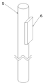
本発明の一実施例を図面を用いて説明する。図1は本発明を実施しているボイラの缶体部分の縦断面図、図2は図1の平面図、図3は本発明のスペーサを抜き出した斜視図である。ボイラ1は伝熱管を螺旋状に巻回した伝熱管壁で缶体を構成している。伝熱管壁は2重のコイルとしており、内側のコイルを内コイル3、外側のコイルを外コイル4とする。内コイル3と外コイル4は間隔を開けて設置しており、内コイル3と外コイル4の間に円環状の燃焼ガス通路7を設ける。内コイル3で囲まれた缶体中心部分を燃焼室8とし、燃焼室8の上部に燃焼装置2を設ける。燃焼装置2は下向きに火炎を発生するものであり、燃焼装置2で燃焼を行うことによって燃焼室8内で熱を発生し、伝熱管を加熱する。
An embodiment of the present invention will be described with reference to the drawings. 1 is a longitudinal sectional view of a can body portion of a boiler embodying the present invention, FIG. 2 is a plan view of FIG. 1, and FIG. 3 is a perspective view of a spacer of the present invention extracted. The
内コイル3は燃焼室8底部との間に間隔を開けて設置し、外コイル4はボイラ内上部と間に間隔を開けて設置することで、内外コイル間の燃焼ガス通路7は底部で燃焼室8と接続し、上部ではボイラ外へつながる排気筒9へと接続する。燃焼室8で発生した燃焼ガスは、燃焼室8底部から燃焼ガス通路7内へ入り、燃焼ガス通路7内を上向きに流れる際に燃焼ガス通路7に面している伝熱管を加熱する。伝熱管内には熱媒体を流すようにしており、伝熱管を加熱することで伝熱管内の熱媒体を加熱する。
The inner coil 3 is installed with a space between the bottom of the combustion chamber 8 and the
内コイル3と外コイル4の間は一定の間隔を開けるようにしており、内コイル3と外コイル4の間にはスペーサを設置する。スペーサは縦に長い丸棒部材であるスペーサ第1部材5と、スペーサ第1部材5に比べて縦方向は短い板状部材であるスペーサ第2部材6からなる。
A constant interval is provided between the inner coil 3 and the
スペーサ第1部材5の太さは、燃焼ガス通路7の幅より僅かに細いものとしておくことで、内コイル3と外コイル4を組み立てた後にもスペーサ第1部材5を燃焼ガス通路7内へ容易に差し込むことができるものとしておく。スペーサ第1部材5の長さは、燃焼ガス通路7の内コイル3と外コイル4で挟まれる部分をほぼ占めるものであり、燃焼ガス通路7にスペーサ第1部材5を差し込んで固定する場合、スペーサ第1部材5の下端は内コイル3の下端部付近、スペーサ第1部材5の上端は外コイル4の上端高さよりも高い位置となるようにしている。スペーサ第1部材5は、燃焼ガス通路7に面している内コイル3の外側に溶接によって固定する。
The thickness of the spacer
スペーサ第1部材5の太さを、燃焼ガス通路7の幅よりも小さなものとした場合、缶体組立の作業性は高くすることができるが、スペーサ第1部材5だけでは内コイル3と外コイル4の偏心は完全には防止できない。そのため、缶体組立の最後でスペーサ第2部材6をスペーサ第1部材5と外コイル4の間に差し込む。スペーサ第2部材6の厚さは、スペーサ第1部材5と足し合わせることで燃焼ガス通路7の幅となるものとする。また、製造上の誤差を吸収するため、スペーサ第2部材6として複数の厚さのものを準備しておき、適切な厚さのものを選択して使用するようにしてもよい。
When the thickness of the spacer
スペーサ第2部材6は縦には短いものであるため、スペーサ第1部材5と外コイル4の間にスペーサ第2部材6を差し込むことはあまり手間を掛けることなく行える。スペーサ第1部材5とスペーサ第2部材6は、それぞれでは燃焼ガス通路7の幅よりも薄ものとしておき、スペーサ第1部材5とスペーサ第2部材6を重ね合わせることで燃焼ガス通路7の幅になるようにしておくことで、内外コイル組立時の偏心を防止でき、偏心防止と作業性向上を両立させることができる。また、スペーサの設置位置は、図2に記載しているように燃焼ガス通路7を三等分した位置に設置すると、燃焼ガス通路7の全周で内コイル3と外コイル4の間隔を揃えることができる。
Since the spacer
なお、本発明は以上説明した実施例に限定されるものではなく、多くの変形が本発明の技術的思想内で当分野において通常の知識を有する者により可能である。 The present invention is not limited to the embodiments described above, and many modifications can be made by those having ordinary knowledge in the art within the technical idea of the present invention.
1 ボイラ
2 燃焼装置
3 内コイル
4 外コイル
5 スペーサ第1部材
6 スペーサ第2部材
7 燃焼ガス通路
8 燃焼室
9 排気筒
10 断熱材
1 boiler
2 Combustion device
3
Claims (1)
It has an inner coil and an outer coil, which are double cylindrical heat transfer tube walls with spirally wound heat transfer tubes, and the center part of the can surrounded by the double coils is the combustion chamber and is generated in the combustion chamber The combustion gas is a member that is vertically elongated in the combustion gas passage in the boiler that heats the heat medium flowing in the heat transfer tube by passing the combustion gas passage provided between the inner coil and the outer coil. A spacer comprising a spacer first member and a spacer second member having a length shorter than that of the spacer first member is installed. The spacer first member and the spacer second member each have a width of the combustion gas passage. It has a helical heat transfer tube that is thinner and has a predetermined interval between the inner coil and the outer coil by overlapping the spacer first member and the spacer second member. Boiler.
Priority Applications (1)
| Application Number | Priority Date | Filing Date | Title |
|---|---|---|---|
| JP2016023099A JP6752023B2 (en) | 2016-02-09 | 2016-02-09 | Boiler with spiral heat transfer tube |
Applications Claiming Priority (1)
| Application Number | Priority Date | Filing Date | Title |
|---|---|---|---|
| JP2016023099A JP6752023B2 (en) | 2016-02-09 | 2016-02-09 | Boiler with spiral heat transfer tube |
Publications (2)
| Publication Number | Publication Date |
|---|---|
| JP2017142012A true JP2017142012A (en) | 2017-08-17 |
| JP6752023B2 JP6752023B2 (en) | 2020-09-09 |
Family
ID=59627815
Family Applications (1)
| Application Number | Title | Priority Date | Filing Date |
|---|---|---|---|
| JP2016023099A Active JP6752023B2 (en) | 2016-02-09 | 2016-02-09 | Boiler with spiral heat transfer tube |
Country Status (1)
| Country | Link |
|---|---|
| JP (1) | JP6752023B2 (en) |
Citations (2)
| Publication number | Priority date | Publication date | Assignee | Title |
|---|---|---|---|---|
| JPS5229642U (en) * | 1975-08-23 | 1977-03-02 | ||
| JPS6153686U (en) * | 1984-09-14 | 1986-04-11 |
-
2016
- 2016-02-09 JP JP2016023099A patent/JP6752023B2/en active Active
Patent Citations (2)
| Publication number | Priority date | Publication date | Assignee | Title |
|---|---|---|---|---|
| JPS5229642U (en) * | 1975-08-23 | 1977-03-02 | ||
| JPS6153686U (en) * | 1984-09-14 | 1986-04-11 |
Also Published As
| Publication number | Publication date |
|---|---|
| JP6752023B2 (en) | 2020-09-09 |
Similar Documents
| Publication | Publication Date | Title |
|---|---|---|
| EP2981780B1 (en) | Plate heat exchanger and method for constructing multiple passes in the plate heat exchanger | |
| CN103517775B (en) | Heat exchanger and its manufacture method | |
| US20140090827A1 (en) | Heat exchanger and production method thereof | |
| RU2016132584A (en) | HEAT EXCHANGER, METHOD OF ITS EDUCATION AND ITS USE | |
| KR20200046076A (en) | Boiler heat exchanger and heat exchanger tube | |
| RU2685759C1 (en) | Profile of pipeline for heat exchangers, heat exchanger for condensing boilers comprising said profile and condensing boiler containing said heat exchanger | |
| RU2018130352A (en) | Internal elements in a spiral-wound heat exchanger for suppressing gas vortices | |
| JP2011214537A (en) | Exhaust gas heat recovery device | |
| JP6752023B2 (en) | Boiler with spiral heat transfer tube | |
| US11162710B2 (en) | Heat exchanger including flue flow path guide system | |
| JP2009535600A (en) | Flat casing water heater | |
| KR20150098140A (en) | a chimney assembly for discharging exhaust gas | |
| CN204612135U (en) | Water Heater and Its Heat Dissipation Utilization Structure | |
| US10598405B2 (en) | Heat exchanger | |
| JP2007085617A (en) | Heat exchanger using micro combustor | |
| CN112586809B (en) | Electronic atomizing device and atomizing assembly thereof | |
| CN210688212U (en) | Low-nitrogen burner fire discharge piece, low-nitrogen burner and gas water heating equipment | |
| KR102581885B1 (en) | Heat Exchanger | |
| JP2006317034A (en) | Heat exchanger and water heating device comprising the same | |
| JP2016023872A (en) | Heat exchanger | |
| TWI686581B (en) | Continuous helical baffle heat exchanger | |
| JP2004225944A (en) | Closing fin structure between water tubes in water tube wall of boiler | |
| KR102325628B1 (en) | Apparatus for generating hot water | |
| JP4415954B2 (en) | Gas heating device | |
| KR200490698Y1 (en) | Instant heating apparatus |
Legal Events
| Date | Code | Title | Description |
|---|---|---|---|
| A621 | Written request for application examination |
Free format text: JAPANESE INTERMEDIATE CODE: A621 Effective date: 20181219 |
|
| A977 | Report on retrieval |
Free format text: JAPANESE INTERMEDIATE CODE: A971007 Effective date: 20191017 |
|
| A131 | Notification of reasons for refusal |
Free format text: JAPANESE INTERMEDIATE CODE: A131 Effective date: 20191029 |
|
| A521 | Request for written amendment filed |
Free format text: JAPANESE INTERMEDIATE CODE: A523 Effective date: 20191202 |
|
| A131 | Notification of reasons for refusal |
Free format text: JAPANESE INTERMEDIATE CODE: A131 Effective date: 20200304 |
|
| A521 | Request for written amendment filed |
Free format text: JAPANESE INTERMEDIATE CODE: A523 Effective date: 20200325 |
|
| TRDD | Decision of grant or rejection written | ||
| A01 | Written decision to grant a patent or to grant a registration (utility model) |
Free format text: JAPANESE INTERMEDIATE CODE: A01 Effective date: 20200812 |
|
| A61 | First payment of annual fees (during grant procedure) |
Free format text: JAPANESE INTERMEDIATE CODE: A61 Effective date: 20200818 |
|
| R150 | Certificate of patent or registration of utility model |
Ref document number: 6752023 Country of ref document: JP Free format text: JAPANESE INTERMEDIATE CODE: R150 |