JP2017145131A - crane - Google Patents
crane Download PDFInfo
- Publication number
- JP2017145131A JP2017145131A JP2016029999A JP2016029999A JP2017145131A JP 2017145131 A JP2017145131 A JP 2017145131A JP 2016029999 A JP2016029999 A JP 2016029999A JP 2016029999 A JP2016029999 A JP 2016029999A JP 2017145131 A JP2017145131 A JP 2017145131A
- Authority
- JP
- Japan
- Prior art keywords
- live mast
- length
- total load
- mast
- boom
- Prior art date
- Legal status (The legal status is an assumption and is not a legal conclusion. Google has not performed a legal analysis and makes no representation as to the accuracy of the status listed.)
- Granted
Links
Images




Landscapes
- Jib Cranes (AREA)
Abstract
Description
本発明は、クレーンに関する。 The present invention relates to a crane.
クローラクレーンの起伏装置には、ライブマスト式(例えば、特許文献1参照)とAフレーム式の2種類がある。ライブマスト式は、Aフレーム式と比べた場合、組立性が良く、また安価に構成できる等の長所がある。 There are two types of crawler crane hoisting devices: a live mast type (see, for example, Patent Document 1) and an A frame type. The live mast type has advantages such as better assembly and lower cost compared to the A frame type.
一方で、同じ長さのブームを引き起こす場合、作業時の後端半径が大きくなってしまうという欠点がある。そのため、狭いところで作業をする場合、後端半径が大きくならないようにブームを寝かせると、最小作業半径が大きくなってしまう。また、それらの欠点を解消するために後端半径の小さなライブマストの短いクレーンを用いた場合、長尺なブームを引き起こせなくなったり、性能が下がったりする等の問題が生じる。 On the other hand, when causing booms of the same length, there is a drawback that the rear end radius at the time of work becomes large. Therefore, when working in a narrow space, if the boom is laid so that the rear end radius is not increased, the minimum working radius is increased. In addition, when a crane with a short live mast with a small rear end radius is used in order to eliminate these disadvantages, problems such as the inability to cause a long boom or a decrease in performance arise.
本発明に係るクレーンは、伸縮構造を有し、起伏ロープにより傾動してブームを起伏させる伸縮可能なライブマストと、前記ライブマストの長さを検出する長さ検出部と、作業半径と定格総荷重との関係を表す定格総荷重曲線が、前記ライブマストの異なる複数の長さに対応して予め複数記憶されている記憶部と、前記検出部で検出された長さに対応する定格総荷重曲線を前記複数の定格総荷重曲線から選択し、選択された定格総荷重曲線に基づいて前記ブームの起伏動作を制限する制限部と、を備える。 A crane according to the present invention has a telescopic structure, an extendable live mast that tilts by a hoisting rope to raise and lower a boom, a length detection unit that detects the length of the live mast, a working radius, and a rated total A total rated load curve representing a relationship with a load is stored in advance corresponding to a plurality of different lengths of the live mast, and a total rated load corresponding to the length detected by the detection unit A limiting unit that selects a curve from the plurality of rated total load curves and limits the hoisting movement of the boom based on the selected rated total load curves.
本発明によれば、ライブマストの長さを変更できるので、作業状況に応じた後端半径とすることが可能となる。 According to the present invention, since the length of the live mast can be changed, the rear end radius according to the work situation can be set.
以下、図面を参照して本発明の一実施の形態について詳細に説明する。
−第1の実施の形態−
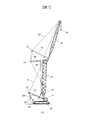
図1は、本発明の第1の実施の形態を示す図である。クローラクレーン1は、下部走行体10と、下部走行体10上に旋回可能に搭載された上部旋回体11と、上部旋回体11の前部に前後方向に起伏可能に軸支されたブーム12とを有する。ブーム12の先端部には前後方向に回動可能にジブ13が取り付けられ、ジブ13の先端部から昇降可能にフック14が吊り下げられている。
Hereinafter, an embodiment of the present invention will be described in detail with reference to the drawings.
-First embodiment-
FIG. 1 is a diagram showing a first embodiment of the present invention. The
ジブ13の基端部にはフロントポスト15が取り付けられ、フロントポスト15とジブ先端部とはジブペンダント17で接続されている。ブーム12の頂部にはリアポスト16が取り付けられている。ジブ起伏ロープ18は、フロントポスト15およびリアポスト16の各先端に設けられたシーブ19,20の間に掛け回されている。ドラム27の駆動によりジブ起伏ロープ18が巻き取りまたは繰り出され、リアポスト16に対してフロントポスト15が回動し、ジブペンダント17を介してジブ13が起伏する。
A
上部旋回体11の前部には、回動可能にライブマスト21が軸支されている。ライブマスト21の先端部とブーム12の頂部とはブームペンダント22で接続されている。ライブマスト21の先端部に設けられたシーブ23と起伏ドラム24の後方に設けられたシーブ25との間には、起伏ロープ26が複数回掛け回されている。起伏ロープ26の一端側は、起伏ドラム24に巻回されている。起伏ドラム24の駆動により起伏ロープ26が巻き取りまたは繰り出されると、ライブマスト21が回動してブームペンダント22を介してブーム12が起伏する。
A
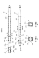
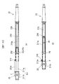
図2は、ライブマスト21の構成の一例を示す図である。本実施の形態におけるライブマスト21はテレスコピック構造を有しており、上部旋回体11の前部に回動可能に軸支される第1マスト部210と、第1マスト部210に対してスライド可能な第2マスト部211を備えている。第2マスト部211の先端部分にはシーブ23が設けられている。図2に示すライブマスト21の場合、図2(a)に示す伸張状態と、図2(b)に示す縮小状態の2種類の長さに設定することができる。なお、図2(c)はD1−D1断面図であり、図2(d)はD2−D2断面図である。
FIG. 2 is a diagram illustrating an example of the configuration of the
第2マスト部211は、第1マスト部210に挿入される挿入部211aと、シーブ23が設けられるシーブ軸支部211bとを有している。挿入部211aには、第2マスト部211の長さを調整するためのピン穴P1、P2が形成されている。図2(a)の伸張状態では、挿入部211aのピン穴P1が第1マスト部210に形成されたピン穴P3と対向するように、挿入部211aの挿入量を調整する。そして、図2(c)に示すように、それらのピン穴P1,P3にピン212を挿通する。その結果、第2マスト部211は、伸張状態で第1マスト部210に固定される。
The
一方、図2(b)に示す縮小状態では、シーブ軸支部211bに形成されたフランジFが第1マスト部210の図示左端に当接するまで、挿入部211aを第1マスト部210の内部に挿入する。その結果、挿入部211aに形成されたピン穴P2が第1マスト部210のピン穴P3に対向する。その後、ピン212をピン穴P2,P3に挿通することで、第2マスト部211は短縮状態で第1マスト部210に固定される。第1マスト部210および第2マスト部211の断面形状は矩形筒状となっているが他の形状でも良く、例えば、円形筒状であっても良い。
On the other hand, in the contracted state shown in FIG. 2B, the
ライブマスト21には、ライブマスト21の伸縮状態を検出するための計測部213が設けられている。図2に示す構成では、計測部213はロータリーポテンショメータであり、計測部213からは連結部材213aが繰り出され、連結部材213aの先端がシーブ軸支部211bのフランジFに固定されている。その結果、ライブマスト21の伸縮状態を計測部213で確認することができる。
The
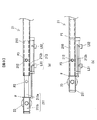
なお、ライブマスト21の伸縮状態を計測する方法としては、図2の構成に限定されない。図3は、計測方法の他の例を示す図である。計測部213はリミットスイッチLS1,LS2およびバー213bで構成されている。バー213bはシーブ軸支部211bのフランジFに固定されており、第2マスト部211の伸縮動作に伴って図示左右方向に移動する。そのため、ライブマスト21の伸縮に伴ってバー213bが左右に移動すると、リミットスイッチLS1,LS2のオンオフ状態が変化する。
In addition, as a method of measuring the expansion-contraction state of the
図3(a)は伸張状態を示しており、バー213bによりリミットスイッチLS1のレバーが押し下げられ、リミットスイッチLS1がオン状態となっている。一方、リミットスイッチLS2はオフ状態になっている。すなわち、リミットスイッチLS1がオン、リミットスイッチLS2はオフの場合には、ライブマスト21は伸張状態となっている。
FIG. 3A shows the extended state, and the lever of the limit switch LS1 is pushed down by the
一方、図3(b)に示す縮小状態では、両方のリミットスイッチLS1,LS2のレバーがバー213bによって押し下げられる。よって、リミットスイッチLS1,LS2の両方がオンの場合には、ライブマスト21は縮小状態となっている。
On the other hand, in the contracted state shown in FIG. 3B, the levers of both limit switches LS1, LS2 are pushed down by the
ライブマスト21の伸縮操作はフロント組立時に行う。例えば、ライブマスト21を上部旋回体11の前部に装着する前に、予め使用状態(図2(a)の伸張状態または図2(b)の縮小状態)にセットしておいても良いし、ライブマスト21を装着した後に補助クレーンを使用して伸張状態または縮小状態にセットするようにしても良い。
The
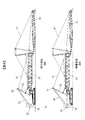
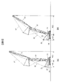
図4,5は、ライブマスト21を伸張状態で使用した場合と、縮小状態で使用した場合のクローラクレーン1の姿勢を示したものである。図4はフロント引き起こし時の姿勢を示し、図5は作業時の姿勢を示す。図4(a)、図5(a)に示す姿勢はライブマスト21を縮小状態で使用する場合であって、図4(b)、図5(b)に示す姿勢はライブマスト21を伸張状態で使用する場合である。
4 and 5 show the posture of the
図4から分かるように、ライブマスト21がより長い伸張状態(図4(b))の方が、シーブ23とシーブ25との距離が離れている。より小さな後端半径で作業を行う必要がある場合には、図4(a)のようにライブマスト21を縮小状態(図2(b)に示す状態)にセットする。一方、小さな後端半径が要求されない場合や、縮小状態のライブマスト21では引き起こせないような長尺のフロントアタッチメントを用いる場合には、図4(b)のようにライブマスト21を伸張状態(図2(a)に示す状態)にセットする。
As can be seen from FIG. 4, the distance between the
図5は、起伏ドラム24の駆動により起伏ロープ26を巻き取ってブーム12を起ち上げた作業状態を示す。図5(a)はライブマスト21が縮小状態の場合を示し、図5(b)はライブマスト21が伸張状態の場合を示す。ライブマスト21を縮小状態にすると、そのときの後端半径r2は伸張状態における後端半径r1よりも小さくなる。
FIG. 5 shows a working state in which the
図6は、比較例として、ライブマストの長さが固定である場合を説明する図である。図6(a)は、最小作業半径をR11とした場合であって、その場合の後端半径はr11である。一方、狭所作業において後端半径をr11よりも小さくする必要がある場合、すなわち、後端半径r12をr11よりも小さくする場合には、図6(b)のようにブーム12を寝かせる必要がある。その場合、最小作業半径が大きくなってしまうという問題がある。図6(b)では、後端半径をr12としたことにより、最小作業半径がR12(>R11)となっている。
FIG. 6 is a diagram illustrating a case where the length of the live mast is fixed as a comparative example. FIG. 6A shows a case where the minimum working radius is R11, in which case the rear end radius is r11. On the other hand, when it is necessary to make the rear end radius smaller than r11 in the narrow work, that is, when the rear end radius r12 is made smaller than r11, it is necessary to lay the
なお、作業半径Rは上部旋回体11の旋回中心から吊り荷までの距離であり、旋回中心からブームフットまでの長さをa、ブーム長さをLa、ブーム角度の検出値をθとすると、次式(1)で算出される。
R=a+La×cosθ …(1)
The working radius R is the distance from the turning center of the
R = a + La × cos θ (1)
ところで、ライブマスト21の長さを変更すると、ライブマスト21とブーム12との幾何学的な関係が変化するので、使用すべき定格総荷重曲線も変化する。そこで、本実施の形態では、ライブマスト21の長さに応じた定格総荷重曲線を自動的に選択し、選択された定格総荷重曲線に基づいて保護動作等を行うように構成した。
By the way, when the length of the
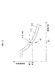
図7はライブマスト21の長さと定格総荷重曲線との関係を説明する図であり、縦軸は定格総荷重、横軸は作業半径である。曲線L11は、ライブマスト21を伸長状態とした場合の定格総荷重曲線である。一方、曲線L12は、ライブマスト21を縮小状態とした場合の定格総荷重曲線である。ライブマスト21を縮小状態とすると、定格総荷重曲線L11,L12から分かるように、同一作業半径R1における定格総荷重は、ライブマスト21を伸長状態とした場合よりも小さくなる。
なお、図中の符号A(R1,W0),A1は第3の実施の形態で説明する。
FIG. 7 is a diagram for explaining the relationship between the length of the
Reference numerals A (R1, W0) and A1 in the figure will be described in the third embodiment.
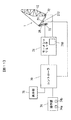
図8は、定格総荷重曲線の切り替え動作に関係する構成を示すブロック図である。運転室内に設けられた操作部74には、クレーンを起動するための起動スイッチ74aが設けられている。コントローラ70には、過負荷防止装置であるモーメントリミッタ71が接続されている。モーメントリミッタ71には、ブーム基端部に設けられた角度検出器72からブーム12の起伏角度(ブーム角度とも呼ばれる)が入力される。また、ロードセルなどの荷重検出器73から起伏ロープ26の張力が入力される。モーメントリミッタ71の記憶部710には、伸張状態および縮小状態の定格総荷重曲線L11,L12(図6参照)がテーブルとして予め記憶されている。表示部75には、クレーン作業の各種情報が表示される。
FIG. 8 is a block diagram showing a configuration related to the switching operation of the rated total load curve. The
定格総荷重曲線とは、作業半径と定格総荷重との関係を表すものである。定格総荷重とは、その作業半径における吊り上げ可能な荷重の限界値であり、クレーンの転倒やブーム12などの構成部材の破損を防止するために設定される。なお、ブーム12には種々の長さのジブ13が接続されるので、記憶部710には使用可能な複数のブーム12と複数のジブ13との組み合わせに応じた定格総荷重曲線がそれぞれ記憶されている。本実施の形態では、同一のブーム12と同一のジブ13について、ライブマスト21の長さの相違により異なる定格総荷重曲線L11とL12が一例として記憶されている。もちろん、異なるブームとジブの組み合わせごとにライブマスト21の長短に応じた2種類の定格総荷重曲線が記憶されている。
The rated total load curve represents the relationship between the working radius and the rated total load. The rated total load is a limit value of a load that can be lifted at the working radius, and is set in order to prevent the crane from falling and the components such as the
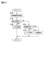
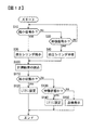
図9は、ライブマスト21の伸縮状態に応じた定格総荷重曲線L11,L12の選択処理の一例を示すフローチャートである。オペレータが操作部74の起動スイッチ74aをオンすると、コントローラ70において図8に示す処理がスタートする。ステップS100では、リミットスイッチLS1,LS2の状態を計測部213から読み込む。
FIG. 9 is a flowchart showing an example of the selection processing of the rated total load curves L11 and L12 according to the expansion / contraction state of the
ステップS110では、計測部213から読み込んだ情報に基づいて、リミットスイッチLS1,LS2が両方ともオンであるか否か、すなわち、ライブマスト21が縮小状態か否かを判定する。ここで、ライブマスト21が縮小状態にある場合には、図3(b)に示すように、リミットスイッチLS1,LS2は両方ともオンとなる。また、図3(a)に示すように伸張状態の場合には、リミットスイッチLS1,LS2は両方ともオフになる。さらに、縮小状態と伸張状態との間の状態の場合には、リミットスイッチLS1はオンで、リミットスイッチLS2はオフ状態になる。
In step S110, based on the information read from the
ステップS110において縮小状態と判定されると、ステップS120へ進んで縮小状態の定格総荷重曲線L12が使用する定格総荷重曲線として設定される。一方、ステップS110でNoと判定されると、ステップS130へ進んでライブマスト21が伸張状態か否かを判定する。リミットスイッチLS1,LS2の両方ともオフの場合には、ステップS130で伸張状態と判定されステップS140へ進む。ステップS140では、使用する定格総荷重曲線として図6の定格総荷重曲線L11が設定される。
If it is determined in step S110 that the state is the reduced state, the process proceeds to step S120, and the rated total load curve L12 in the reduced state is set as the rated total load curve used. On the other hand, if it is determined No in step S110, the process proceeds to step S130 to determine whether or not the
ステップS130でNoと判定された場合、すなわち、リミットスイッチLS1がオンでリミットスイッチLS2がオフである場合には、ライブマスト21が中途半端な長さになっていると判定される。また、リミットスイッチLS1,LS2の状態が正常である場合には起こり得ないリミットスイッチLS1がオフでリミットスイッチLS2がオンの場合には、リミットスイッチが故障している可能性がある。いずれの場合にも、ステップS130からステップS150へ進んで、ライブマスト21の状態の点検を促す表示を表示部75に表示する。
When it is determined No in step S130, that is, when the limit switch LS1 is on and the limit switch LS2 is off, it is determined that the
上述したように、本実施の形態では、ライブマスト21の長さを可変としたので、後端半径が制限される狭い作業環境においてはライブマスト21を短くして使用し、後端半径に余裕のある作業環境においてはライブマスト21を伸長状態で使用することができる。すなわち、作業環境に応じてライブマスト21の長さを変更することができる。
As described above, since the length of the
さらに、上述した実施の形態では、ライブマスト21の長さ状態(伸張状態、縮小状態)を計測部123で計測し、その計測結果に基づいて最適な定格総荷重曲線を自動的に設定するようにした。それにより、ライブマスト21の長さを変更しても、作業機械を安定動作させることができる。
Furthermore, in the above-described embodiment, the measurement unit 123 measures the length state (expanded state, contracted state) of the
なお、上述した実施形態では、ライブマスト21を、縮小状態と伸長状態との2種類の長さに設定可能としたが、3種類以上の長さに設定できるような構成としても良い。
In the above-described embodiment, the
以上説明した第1の実施の形態によれば、次の作用効果が得られる。
(1)クローラクレーン1は、図2に示すような伸縮構造を有し、起伏ロープにより傾動してブーム12を起伏させる伸縮可能なライブマスト21と、ライブマスト21の長さを検出する長さ検出部である計測部213と、図7に示すような作業半径と定格総荷重との関係を表す定格総荷重曲線L11,L12が、ライブマスト21の異なる複数の長さに対応して予め複数記憶されている記憶部710と、計測部213で検出された長さに対応する定格総荷重曲線を複数の定格総荷重曲線L11,L12から選択し、選択された定格総荷重曲線に基づいてブーム12の起伏動作を制限する制限部であるモーメントリミッタ71と、を備える。このように、ライブマスト21の長さが変更可能な場合において、ライブマスト21の長さを変更すると変更後の定格総荷重曲線に自動的に設定されるので、ライブマスト21の長さを変更してもモーメントリミッタ71による制限動作を適切に行うことができる。
According to the first embodiment described above, the following operational effects can be obtained.
(1) The
−第2の実施の形態−
図10は、第2の実施の形態におけるライブマスト21を示す図である。図10(a)は伸張状態のライブマスト21を示し、図10(b)は縮小状態のライブマスト21を示す。上述した第1の実施の形態のクレーンでは、図2に示すような伸縮可能な構成のライブマスト21が採用された。ただし、ライブマスト21の伸縮作業そのものは、手作業で行ったり、他の補助機械(例えばクレーン)を用いたりして行われる。一方、第2の実施の形態では、図10に示すように、油圧シリンダ215を用いて伸縮させる構成のライブマスト21を採用する。
-Second Embodiment-
FIG. 10 is a diagram illustrating the
ライブマスト21の長さを検出する計測部213には、図2の場合と同様にロータリーポテンショメータや、図3に示したリミットスイッチLS1,LS2等が設けられている。第1マスト部210には油圧シリンダ215が設けられている。油圧シリンダ215のピストンロッド215aの先端は、第2マスト部211の挿入部211aの図示右端に接続されている。油圧シリンダ215を伸張すると、挿入部211aが第1マスト部210から繰り出されてライブマスト21の長さが増加する。
The
図10(a)に示す伸張状態は挿入部211aが最も繰り出された状態であり、ライブマスト21をこの状態に固定するためのピン212が装着されている。このピン212は、第1マスト部210に形成されたピン穴P3、および、第2マスト部211の挿入部211aに形成されたピン穴P1に挿通されている。一方、図10(b)は縮小状態を示し、第2マスト部211のシーブ軸支部211bに設けられたフランジFが第1マスト部210に当接するまで挿入部211aが繰り込まれている。
The extended state shown in FIG. 10A is a state in which the
図11は、上述した図8に対応するブロック図である。第2の実施の形態では、操作部74に設けられた伸縮指示スイッチ74bを操作することで、油圧シリンダ215を伸縮させてライブマスト21を伸張状態および縮小状態にすることができる。例えば、伸縮指示スイッチ74bをトグルスイッチとし、一方に操作すると伸張状態となり、他方に操作すると縮小状態となる。伸縮指示スイッチ74bの操作に応じて、ライブマスト21の縮小を指示する縮小信号または伸張を指示する伸張信号が操作部74からコントローラ70へ出力される。
FIG. 11 is a block diagram corresponding to FIG. 8 described above. In the second embodiment, by operating an expansion /
図12は、ライブマスト21の伸縮処理の一例を示すフローチャートである。本実施の形態におけるライブマスト21では、図4のようにフロント部を倒した状態で、予めライブマスト21の長さを伸張状態または縮小状態にする。
FIG. 12 is a flowchart showing an example of the expansion / contraction process of the
図12のフローチャートは、図9に示すフローチャートにステップS10からステップS40までの処理を追加したものである。よって、以下では、ステップS100〜ステップS150までの説明を省略し、ステップS10〜ステップS40の処理について説明する。図12の処理は、操作部74の起動スイッチ74aがオンされるとスタートする。
The flowchart of FIG. 12 is obtained by adding processes from step S10 to step S40 to the flowchart shown in FIG. Therefore, below, the description from step S100 to step S150 is omitted, and the processing from step S10 to step S40 will be described. The process of FIG. 12 starts when the
ステップS10では、オペレータにより伸縮指示スイッチ74bが操作され、その操作により操作部74からコントローラ70に入力される指示が、縮小信号か否かを判定する。ステップS10で縮小信号と判定されると、ステップS20へ進み、油圧シリンダ215を図10(b)に示すように収縮させる。
In step S10, the operator operates the expansion /
一方、ステップS10でNoと判定されると、ステップS30へ進んでコントローラ70に入力される指示が伸張信号か否かを判定する。ステップS30で伸張信号と判定されると、ステップS40へ進んで図10(a)のように油圧シリンダ215を伸張状態にする。オペレータが伸縮指示スイッチ74bを未操作の間は、ステップS30からステップS10へ戻ることになる。
On the other hand, if it is determined No in step S10, the process proceeds to step S30 to determine whether or not the instruction input to the
油圧シリンダ215が伸張状態とされた場合には、オペレータまたは他の作業員によって図10(a)に示すようにピン穴P1,P3にピン212が挿通される。その結果、ライブマスト21は伸張状態に固定される。ここで、ピン212で伸張状態に固定するのは、作業時に油圧シリンダ215に過大な力が掛からないようにするためである。油圧シリンダ215は、ライブマスト21の伸縮動作に必要な力を出せる程度のものが用いられる。一方、縮小状態の場合には、図10(b)に示すように、シーブ軸支部211bのフランジFが第1マスト部210の端面に当接し、フランジFによって力を受ける構成となっているので、ピン212を使用しなくても済む。もちろん、縮小状態でもピン212を用いるような構成としても良い。
When the
以上のように、第2の実施の形態では、油圧シリンダ215を用いて予めライブマスト21を縮小状態および伸張状態に設定することができるので、第1の実施の形態の構成に比べて作業性に優れている。なお、第1の実施の形態の場合と同様に、ライブマスト21の伸縮状態に応じて自動的に定格総荷重曲線がL1またはL2に設定される。なお、第2の実施の形態では、油圧シリンダ215は、段取り作業時にライブマスト21を伸縮動作させるに必要な力を出せる程度のものとしている。したがって、後述するように、作業姿勢でライブマスト21を伸縮可能とする油圧シリンダに比べて、シリンダ径が小さい油圧シリンダを採用することができ、これにより、ライブマスト21のコストアップを抑制するようにしている。
As described above, in the second embodiment, the
−第3の実施の形態−
上述した第2の実施の形態では、油圧シリンダ215として比較的小径のシリンダを使用することでコストアップを抑制するようにした。一方、第3の実施の形態では、油圧シリンダ215として第2の実施の形態に使用されるものよりも太い径の油圧シリンダを使用することで、ピン212を使用しなくても作業時の負荷に耐えられるようにすると共に、例えば、図1に示すようにフロント部を起き上げた状態においても、ライブマスト21の長さを変更できるようにした。なお、ライブマスト21の構成は基本的に図10に示す構成と同様であって、油圧シリンダ215がより大径になっている点が異なるだけなので、ライブマスト21の構成についての説明は省略する。
-Third embodiment-
In the second embodiment described above, an increase in cost is suppressed by using a relatively small diameter cylinder as the
図13は、第3の実施の形態におけるライブマスト21の伸縮動作を説明するフローチャートである。なお、図13に示すフローチャートは、図12に示したフローチャートにステップS15およびステップS16の処理を追加したものである。以下では、図12のフローチャートと異なる部分について説明する。
FIG. 13 is a flowchart for explaining the expansion / contraction operation of the
ステップS10で縮小信号と判定された場合は、本実施の形態の場合には直ちに油圧シリンダ215の縮小動作を実行せずに、ステップS15の処理が行われる。一方、ステップS10でNoと判定された場合には、上述した第2の実施の形態の場合と同様にステップS30へ進む。ステップS30に進んだ場合のステップS30以降の処理は、上述した図12の場合と同様の処理が行われる。
If it is determined in step S10 that the signal is a reduction signal, the process of step S15 is performed without immediately executing the reduction operation of the
ステップS15では、ライブマスト21を縮小状態とした場合の定格総荷重曲線L12と、角度検出器72から出力されるブーム12の起伏角度に基づく作業半径とから、ライブマスト21を縮小状態とした場合に推定される定格総荷重(以下では、推定定格総荷重と呼ぶことにする)を算出する。そして、算出された推定定格総荷重が、荷重検出器73から出力される張力に基づく吊り総荷重(フック14の重量も含めた吊り荷重)よりも大きいか否かを判定する。
In step S15, when the
図7に示す点A(R1、W0)は、ライブマスト21を縮小状態とする前(すなわち、伸張状態)における作業半径(=R1)と吊り総荷重(=W0)とで表される座標上の点の一例を示したものである。作業半径は現時点(伸張状態)の作業半径R1であり、吊り総荷重はW0である。図7に示す例では、ライブマスト21の長さが定格総荷重曲線L11に対応する伸張状態であれば、作業半径R1では、吊り総荷重は推定定格総荷重W11まで許容される。しかし、ライブマスト21の長さが縮小状態である場合には定格総荷重曲線L12に設定されるので、作業半径R1における吊り総荷重は推定定格総荷重W12までしか許容されない。
A point A (R1, W0) shown in FIG. 7 is on the coordinates represented by the working radius (= R1) and the total suspended load (= W0) before the
そこで、本実施形態では、ステップS15において「(推定定格総荷重W12)≦(吊り総荷重)」と判定された場合には、すなわち、図7の点A(R1、W0)で表される状況においては、縮小信号を受信しても縮小動作は行わずに、ステップS16に進む。ステップS16では、ライブマスト21の縮小動作が禁止されたことを報知する警報(警報表示)を、表示部75に表示する。
Therefore, in this embodiment, when it is determined in step S15 that “(estimated rated total load W12) ≦ (total suspended load)”, that is, the situation represented by the point A (R1, W0) in FIG. In step S16, the reduction operation is not performed even if the reduction signal is received, and the process proceeds to step S16. In step S <b> 16, an alarm (alarm display) for notifying that the reduction operation of the
一方、例えば、現在の作業半径R1と吊り総荷重との関係が点A1で表されるように、ライブマスト21を縮小状態としたときの定格総荷重曲線L12よりも下側である場合には、ステップS15において「(推定定格総荷重W12)>(吊り総荷重)」と判定され、ステップS20へ進む。ステップS20では油圧シリンダ215を縮小させ、ライブマスト21を縮小状態とする。ステップS20以降の処理は、上述した第2の実施の形態の場合と同様である。
On the other hand, for example, when the relationship between the current working radius R1 and the total suspended load is represented by a point A1, when the
このように、第3の実施の形態では、ライブマスト21の長さ変更が作業状態においても可能な構成とされる。さらに、ライブマスト21の長さ変更時に、縮小状態における定格総荷重曲線L12に基づく推定定格総荷重が吊り総荷重以下である場合には、オペレータがライブマスト21の縮小を指示しても、縮小動作を禁止するように構成した。その結果、ライブマスト21の伸縮動作を安全に行うことができる。
Thus, in the third embodiment, the length of the
以上説明した第3の実施の形態によれば、次の作用効果が得られる。
(2)クローラクレーン1は、ライブマスト21を第1の長さ(伸張状態の長さ)および第1の長さよりも短い第2の長さ(縮小状態の長さ)に伸縮する油圧シリンダ215と、吊り総荷重を検出する荷重検出器73と、ブーム12のブーム角を検出する角度検出器72と、ライブマスト21の伸長を指示する伸長信号と、ライブマスト21の縮小を指示する縮小信号とが入力され、入力された伸長信号および縮小信号に基づいてライブマスト21の伸縮を制御する制御部であるコントローラ70と、を備え、記憶部710には伸張状態に対応する第1定格総荷重曲線(L11)と縮小状態に対応する第2定格総荷重曲線(L12)とが記憶される。
According to the third embodiment described above, the following operational effects can be obtained.
(2) The
そして、コントローラ70は、第2定格総荷重曲線と角度検出器72で検出されたブーム角度に基づく作業半径とに基づいて推定される推定定格総荷重が、荷重検出器73で検出された吊り総荷重以下である場合には、ライブマスト21の縮小を禁止する。その結果、吊り荷を吊った状態でライブマスト21の縮小をオペレータが指示しても、その時の吊り総荷重が縮小状態における定格総荷重以上と推定される場合には、ライブマスト21の縮小動作が禁止されるので、安全が確保される。
Then, the
−第4の実施の形態−
図14は、第4の実施の形態を説明するためのフローチャートである。上述した第3の実施の形態では、作業中であってもライブマスト21の伸縮動作が可能な構成としたが、本実施の形態でも同様の構成とする。
-Fourth embodiment-
FIG. 14 is a flowchart for explaining the fourth embodiment. In the above-described third embodiment, the
第1の実施の形態で説明した図5では、ライブマスト21を縮小状態とした場合(図5(a))と、伸張状態とした場合(図5(b))とを示した。第1の実施の形態では図2,3に示すライブマスト21を使用し、予めライブマスト21の長さを縮小状態または伸張状態としてから、フロント部を起き上げるようにした。図5に示す例では、起き上げた後に起伏ロープ26の繰り出し量を調整することにより、図5(a)の縮小状態と図5(b)の伸張状態とでブーム12の起伏角度が同じになるようにしている。
FIG. 5 described in the first embodiment shows a case where the
一方、作業中に油圧シリンダ215を伸縮させてライブマスト21の長さを変更する場合、変更前と変更後とではブーム12の起伏角度が若干変化し、作業半径も変化することになる。そこで、本実施形態では、ライブマスト21の長さを変更する際に、起伏ドラム24の駆動により起伏ロープ26を巻き取りまたは繰り出すことにより、作業半径が変化しないようにライブマスト21の伸縮動作をさせるようにした。
On the other hand, when the length of the
図14のフローチャートでは、図12のフローチャートのステップS20およびステップS40の処理を、ステップS25およびステップS45の処理で置き換えている。その他の処理は図12の場合と同様である。 In the flowchart of FIG. 14, the processes of step S20 and step S40 in the flowchart of FIG. 12 are replaced with the processes of step S25 and step S45. Other processes are the same as those in FIG.
ステップS10において縮小信号と判定されると、ステップS25に進む。ステップS25では、油圧シリンダ215を伸長状態から縮小させると共に、作業半径が変化しないように油圧シリンダ215の縮小動作に連動して起伏ロープ26を巻き取る。また、ステップS30において伸張信号と判定されると、ステップS45に進む。ステップS45では、油圧シリンダ215を縮小状態から伸長させると共に、作業半径が変化しないように油圧シリンダ215の伸張動作に連動して起伏ロープ26を繰り出す。
If it is determined in step S10 that the signal is a reduced signal, the process proceeds to step S25. In step S25, the
このように、第4の実施の形態では、ライブマスト21の長さを変更した場合でも作用半径が変化しないので、吊り荷が周囲にある物や作業員などに干渉するのを防止することができ、周囲で作業している作業員に対して安全が確保される。
As described above, in the fourth embodiment, even when the length of the
以上説明した第4の実施の形態によれば、次の作用効果が得られる。 According to the fourth embodiment described above, the following operational effects can be obtained.
(3)コントローラ70は、ライブマスト21を伸縮させる場合に、ブーム12の作業半径が一定に維持されるようにライブマスト21を起伏する起伏装置である起伏ドラム24の動作を制御する。そのような制御を行うことによって、ライブマスト21の伸縮動作を安全に行うことができる。
(3) When the
上記では、種々の実施の形態および変形例を説明したが、本発明はこれらの内容に限定されるものではない。本発明の技術的思想の範囲内で考えられるその他の態様も本発明の範囲内に含まれる。また、上述した実施形態および各変形例はそれぞれ単独に、あるいは組み合わせて用いても良い。 Although various embodiments and modifications have been described above, the present invention is not limited to these contents. Other embodiments conceivable within the scope of the technical idea of the present invention are also included in the scope of the present invention. Moreover, you may use embodiment mentioned above and each modification individually or in combination.
1…クローラクレーン(クレーン)、12…ブーム、21…ライブマスト、24…起伏ドラム(起伏装置)、26…起伏ロープ、70…コントローラ(制御部)、71…モーメントリミッタ(制限部)、72…角度検出器、73…荷重検出器、74…操作部、213…計測部(検出部)、215…油圧シリンダ、710…記憶部、L11,L12…定格総荷重曲線
DESCRIPTION OF
Claims (3)
前記ライブマストの長さを検出する長さ検出部と、
作業半径と定格総荷重との関係を表す定格総荷重曲線が、前記ライブマストの異なる複数の長さに対応して予め複数記憶されている記憶部と、
前記検出部で検出された長さに対応する定格総荷重曲線を前記複数の定格総荷重曲線から選択し、選択された定格総荷重曲線に基づいて前記ブームの起伏動作を制限する制限部と、を備えることを特徴とするクレーン。 A telescopic live mast that has a telescopic structure and tilts with a hoisting rope to raise and lower the boom,
A length detector for detecting the length of the live mast;
A storage unit in which a plurality of rated total load curves representing a relationship between a working radius and a rated total load are stored in advance corresponding to a plurality of different lengths of the live mast;
A rated total load curve corresponding to the length detected by the detection unit is selected from the plurality of rated total load curves, and a limiting unit that limits the hoisting operation of the boom based on the selected rated total load curve; A crane comprising:
前記ライブマストを第1の長さおよび前記第1の長さよりも短い第2の長さに伸縮する油圧シリンダと、
吊り総荷重を検出する吊り荷重検出器と、
前記ブームのブーム角を検出する角度検出器と、
前記ライブマストの前記第1の長さへの伸長を指示する伸長信号と、前記ライブマストの前記第2の長さへの縮小を指示する縮小信号とが入力され、入力された前記伸長信号および前記縮小信号に基づいて前記ライブマストの伸縮を制御する制御部と、を備え、
前記記憶部には前記第1の長さに対応する第1定格総荷重曲線と前記第2の長さに対応する第2定格総荷重曲線とが記憶され、
前記制御部は、前記第2定格総荷重曲線と前記角度検出器で検出されたブーム角度に基づく作業半径とに基づいて推定される推定定格総荷重が、前記吊り荷重検出器で検出された吊り総荷重以下である場合には、前記ライブマストの前記第2の長さへの縮小を禁止することを特徴とするクレーン。 The crane according to claim 1,
A hydraulic cylinder that expands and contracts the live mast to a first length and a second length shorter than the first length;
A suspension load detector for detecting the total suspension load;
An angle detector for detecting a boom angle of the boom;
An extension signal instructing extension of the live mast to the first length and a reduction signal instructing reduction of the live mast to the second length are input, and the input extension signal and A control unit that controls expansion and contraction of the live mast based on the reduced signal,
The storage unit stores a first rated total load curve corresponding to the first length and a second rated total load curve corresponding to the second length,
The control unit is configured to suspend an estimated rated total load estimated based on the second rated total load curve and a work radius based on a boom angle detected by the angle detector. When the total load is equal to or less than the total load, the live mast is prohibited from being reduced to the second length.
前記制御部は、前記ライブマストを伸縮させる場合に、前記ブームの作業半径が一定に維持されるように前記ライブマストを起伏する起伏装置を制御することを特徴とするクレーン。 The crane according to claim 2,
The said control part is a crane characterized by controlling the raising / lowering apparatus which raises / lowers the said live mast so that the working radius of the said boom may be maintained constant, when expanding / contracting the said live mast.
Priority Applications (1)
| Application Number | Priority Date | Filing Date | Title |
|---|---|---|---|
| JP2016029999A JP6534944B2 (en) | 2016-02-19 | 2016-02-19 | crane |
Applications Claiming Priority (1)
| Application Number | Priority Date | Filing Date | Title |
|---|---|---|---|
| JP2016029999A JP6534944B2 (en) | 2016-02-19 | 2016-02-19 | crane |
Publications (2)
| Publication Number | Publication Date |
|---|---|
| JP2017145131A true JP2017145131A (en) | 2017-08-24 |
| JP6534944B2 JP6534944B2 (en) | 2019-06-26 |
Family
ID=59682764
Family Applications (1)
| Application Number | Title | Priority Date | Filing Date |
|---|---|---|---|
| JP2016029999A Active JP6534944B2 (en) | 2016-02-19 | 2016-02-19 | crane |
Country Status (1)
| Country | Link |
|---|---|
| JP (1) | JP6534944B2 (en) |
Cited By (4)
| Publication number | Priority date | Publication date | Assignee | Title |
|---|---|---|---|---|
| JP2017154846A (en) * | 2016-02-29 | 2017-09-07 | 日立住友重機械建機クレーン株式会社 | crane |
| JP2019190063A (en) * | 2018-04-20 | 2019-10-31 | 日本車輌製造株式会社 | Earth drill |
| JP2019218193A (en) * | 2018-06-21 | 2019-12-26 | コベルコ建機株式会社 | Tension increase device for derricking rope and tension increase method thereof |
| WO2023176673A1 (en) * | 2022-03-17 | 2023-09-21 | コベルコ建機株式会社 | Sheave device retracting and unfolding method |
Citations (5)
| Publication number | Priority date | Publication date | Assignee | Title |
|---|---|---|---|---|
| JPH09194190A (en) * | 1995-11-13 | 1997-07-29 | Sumitomo Constr Mach Co Ltd | Jib rising and falling device |
| JPH10203786A (en) * | 1997-01-23 | 1998-08-04 | Hitachi Constr Mach Co Ltd | Construction machine with moment limiter |
| JP2004307215A (en) * | 2003-04-08 | 2004-11-04 | Manitowoc Crane Co Inc | Tensioning system for mobile telescopic crane |
| JP2008143627A (en) * | 2006-12-07 | 2008-06-26 | Hitachi Sumitomo Heavy Industries Construction Crane Co Ltd | Safety device of crane |
| JP2015071487A (en) * | 2013-10-04 | 2015-04-16 | 株式会社神戸製鋼所 | Crane and method for assembling crane |
-
2016
- 2016-02-19 JP JP2016029999A patent/JP6534944B2/en active Active
Patent Citations (5)
| Publication number | Priority date | Publication date | Assignee | Title |
|---|---|---|---|---|
| JPH09194190A (en) * | 1995-11-13 | 1997-07-29 | Sumitomo Constr Mach Co Ltd | Jib rising and falling device |
| JPH10203786A (en) * | 1997-01-23 | 1998-08-04 | Hitachi Constr Mach Co Ltd | Construction machine with moment limiter |
| JP2004307215A (en) * | 2003-04-08 | 2004-11-04 | Manitowoc Crane Co Inc | Tensioning system for mobile telescopic crane |
| JP2008143627A (en) * | 2006-12-07 | 2008-06-26 | Hitachi Sumitomo Heavy Industries Construction Crane Co Ltd | Safety device of crane |
| JP2015071487A (en) * | 2013-10-04 | 2015-04-16 | 株式会社神戸製鋼所 | Crane and method for assembling crane |
Cited By (7)
| Publication number | Priority date | Publication date | Assignee | Title |
|---|---|---|---|---|
| JP2017154846A (en) * | 2016-02-29 | 2017-09-07 | 日立住友重機械建機クレーン株式会社 | crane |
| JP2019190063A (en) * | 2018-04-20 | 2019-10-31 | 日本車輌製造株式会社 | Earth drill |
| JP2019218193A (en) * | 2018-06-21 | 2019-12-26 | コベルコ建機株式会社 | Tension increase device for derricking rope and tension increase method thereof |
| JP7110753B2 (en) | 2018-06-21 | 2022-08-02 | コベルコ建機株式会社 | Device for increasing tension of luffing rope and method for increasing tension of luffing rope |
| WO2023176673A1 (en) * | 2022-03-17 | 2023-09-21 | コベルコ建機株式会社 | Sheave device retracting and unfolding method |
| JP2023136408A (en) * | 2022-03-17 | 2023-09-29 | コベルコ建機株式会社 | Sheave device storing and developing method |
| JP7771827B2 (en) | 2022-03-17 | 2025-11-18 | コベルコ建機株式会社 | Sheave device storage and deployment method |
Also Published As
| Publication number | Publication date |
|---|---|
| JP6534944B2 (en) | 2019-06-26 |
Similar Documents
| Publication | Publication Date | Title |
|---|---|---|
| US11459218B2 (en) | Crane and crane posture changing method | |
| JP6534944B2 (en) | crane | |
| JP5616658B2 (en) | Boom working machine | |
| JP4939701B2 (en) | Luggage ground cutting method and apparatus using boom crane | |
| JP3219185U (en) | Mobile crane | |
| JP6772765B2 (en) | Image display device | |
| JP2017052577A (en) | Safety device of working machine | |
| JP6708986B2 (en) | How to change the orientation of the crane and crane | |
| JP5570197B2 (en) | Boom deflection control device for a working machine with a boom | |
| JP5502447B2 (en) | Boom deflection suppressing device for a working machine with a boom | |
| JP6524772B2 (en) | Boom length restriction device | |
| JP5271122B2 (en) | Boom and jib lateral deflection suppressing device for boom working vehicle with jib | |
| JP4788490B2 (en) | Elevating mechanism of hoisting members | |
| JP5384813B2 (en) | Safety equipment for work equipment | |
| JP7253930B2 (en) | Tension overload protector and crane | |
| JP6388095B2 (en) | crane | |
| JP2018131303A (en) | Crane device with jib | |
| JP2005306602A (en) | Load lift-off device used for boom type crane | |
| JP6642203B2 (en) | crane | |
| JP4988990B2 (en) | Crane jib undulation controller | |
| JP5448769B2 (en) | Boom deflection suppressing device for a working machine with a boom | |
| JP7786068B2 (en) | Crane load increase prevention device | |
| JP6753558B2 (en) | Safety devices for cranes, cranes, safety control methods for cranes, and safety control programs for cranes | |
| JP5948009B2 (en) | Crane equipment | |
| JP2011121729A (en) | Working machine with boom |
Legal Events
| Date | Code | Title | Description |
|---|---|---|---|
| A625 | Written request for application examination (by other person) |
Free format text: JAPANESE INTERMEDIATE CODE: A625 Effective date: 20180517 |
|
| A977 | Report on retrieval |
Free format text: JAPANESE INTERMEDIATE CODE: A971007 Effective date: 20190516 |
|
| TRDD | Decision of grant or rejection written | ||
| A01 | Written decision to grant a patent or to grant a registration (utility model) |
Free format text: JAPANESE INTERMEDIATE CODE: A01 Effective date: 20190528 |
|
| A61 | First payment of annual fees (during grant procedure) |
Free format text: JAPANESE INTERMEDIATE CODE: A61 Effective date: 20190530 |
|
| R150 | Certificate of patent or registration of utility model |
Ref document number: 6534944 Country of ref document: JP Free format text: JAPANESE INTERMEDIATE CODE: R150 |