JP2017149209A - Cover for two-wheel vehicle - Google Patents
Cover for two-wheel vehicle Download PDFInfo
- Publication number
- JP2017149209A JP2017149209A JP2016031944A JP2016031944A JP2017149209A JP 2017149209 A JP2017149209 A JP 2017149209A JP 2016031944 A JP2016031944 A JP 2016031944A JP 2016031944 A JP2016031944 A JP 2016031944A JP 2017149209 A JP2017149209 A JP 2017149209A
- Authority
- JP
- Japan
- Prior art keywords
- wheeled vehicle
- cover
- plug
- wheel
- motorcycle
- Prior art date
- Legal status (The legal status is an assumption and is not a legal conclusion. Google has not performed a legal analysis and makes no representation as to the accuracy of the status listed.)
- Granted
Links
- 238000010276 construction Methods 0.000 claims description 17
- 239000004744 fabric Substances 0.000 description 57
- 238000009958 sewing Methods 0.000 description 15
- 230000000694 effects Effects 0.000 description 7
- 239000000463 material Substances 0.000 description 7
- 239000000470 constituent Substances 0.000 description 5
- 230000035699 permeability Effects 0.000 description 5
- 238000004519 manufacturing process Methods 0.000 description 4
- XLYOFNOQVPJJNP-UHFFFAOYSA-N water Substances O XLYOFNOQVPJJNP-UHFFFAOYSA-N 0.000 description 3
- 239000002828 fuel tank Substances 0.000 description 2
- 238000000034 method Methods 0.000 description 2
- 230000002093 peripheral effect Effects 0.000 description 2
- 229920001225 polyester resin Polymers 0.000 description 2
- 239000004645 polyester resin Substances 0.000 description 2
- 230000009993 protective function Effects 0.000 description 2
- YCKRFDGAMUMZLT-UHFFFAOYSA-N Fluorine atom Chemical compound [F] YCKRFDGAMUMZLT-UHFFFAOYSA-N 0.000 description 1
- 239000000835 fiber Substances 0.000 description 1
- 229910052731 fluorine Inorganic materials 0.000 description 1
- 239000011737 fluorine Substances 0.000 description 1
- 239000003779 heat-resistant material Substances 0.000 description 1
- 238000009434 installation Methods 0.000 description 1
- 239000004745 nonwoven fabric Substances 0.000 description 1
- 229920005989 resin Polymers 0.000 description 1
- 239000011347 resin Substances 0.000 description 1
- 229920003002 synthetic resin Polymers 0.000 description 1
- 239000000057 synthetic resin Substances 0.000 description 1
- 238000004804 winding Methods 0.000 description 1
- 239000002759 woven fabric Substances 0.000 description 1
Images





Landscapes
- Professional, Industrial, Or Sporting Protective Garments (AREA)
Abstract
Description
本発明は、二輪車を覆うためのカバーに関する。前記二輪車は、例えば自動二輪車または自転車等が挙げられる。 The present invention relates to a cover for covering a two-wheeled vehicle. Examples of the motorcycle include a motorcycle and a bicycle.
従来のこの種のカバーとして、例えば特許文献1,2に記載されているようなカバーが知られている。
As this type of conventional cover, for example, a cover described in
このカバーは、下側が開放されたワンピースの袋とされている。このようなカバーは、一般に、二輪車への装着を容易とするために外形サイズを比較的大きく設定しておき、雨や風等によって全体がバタつかないようにするため、ならびに車体から簡単に外れないようにするために、固定手段を装備するようになっている。 The cover is a one-piece bag with the bottom open. Such a cover is generally set to a relatively large external size for easy mounting on a motorcycle, so that it does not flutter completely due to rain, wind, etc. In order to prevent it, it is equipped with fixing means.
上記特許文献1では、前記固定手段として、絞り紐と、面ファスナーとを用いている。前記絞り紐は、カバーの下側開放部分の外周縁に設置されていて、車体後端側で絞り操作することによって前記下側開放部分を窄ませるようになっている。前記面ファスナーは、カバーの下側開放部分において車体前後方向の中間部位に設置されていて、当該下側開放部分を車体幅方向に狭めるようになっている。 In the said patent document 1, a drawstring and a hook-and-loop fastener are used as the said fixing means. The throttle string is installed on the outer peripheral edge of the lower open portion of the cover, and the lower open portion is squeezed by performing a throttle operation on the rear end side of the vehicle body. The hook-and-loop fastener is installed at an intermediate portion in the longitudinal direction of the vehicle body in the lower open portion of the cover, and the lower open portion is narrowed in the vehicle body width direction.
上記特許文献2では、前記固定手段として、絞り紐を用いている。この絞り紐は、カバーの下側開放部分の外周縁に設置されていて、車体後端側で絞り操作することによって前記下側開放部分を窄ませるようになっている。
In the said
その他にも、例えば特許文献3には、二輪車の上下左右の全域を覆うようにするカバーが記載されている。このカバーは、装着前の状態で矩形状に形成されており、それを設置場所に広げた状態で敷いておき、当該カバーにおいて車体幅方向のセンターに二輪車を載せてから、当該カバーにおいて車体幅方向の両端を二輪車の上方で突き合わせるように2つ折りにし、この突き合わせ部分をスライドファスナーで閉じることにより、二輪車に装着するようになっている。
In addition, for example,
さらに、例えば特許文献4には、自動二輪車のマフラー部分を覆うようにしたバイクマフラー用熱カバーが記載されている。このカバーは、自動二輪車の車体前後方向の後半領域のみを覆う外形寸法の袋とされていて、耐熱性材料で形成されている。
Furthermore, for example,
上記特許文献1,2は、大型自動二輪車等のように車体前後方向の寸法が大きい場合だと、二輪車の前輪側にカバーを被せておいて、作業者が二輪車の側方から後方に移動しながら二輪車の後輪側にカバーを被せるように作業しなければならないので、二輪車にカバーを1人で被せることが難しいと言える。
In
また、上記特許文献3は、カバーを地面に広げた状態で二輪車を載せる際に、仮に前記載せた位置がカバーにおける車体幅方向のセンターから左右方向にずれてしまうと、その後でカバーを2つ折りにする作業が困難になるので、二輪車をカバー上に載せる作業をやり直す必要がある等、面倒であるとともに、比較的大きな作業スペースを確保する必要があると言える。
Further, in
さらに、上記特許文献4は、二輪車の全体を覆うものでなく、バイクの後半領域のみを覆うだけの外形寸法になっているために、その他の部分を覆うには、上記特許文献1〜3のようなカバーを用いる必要がある。
Furthermore, since the above-mentioned
このような事情に鑑み、本発明は、二輪車用のカバーにおいて、二輪車に比較的タイトにフィットするスリムな形状にできるようにしながら、二輪車に1人で比較的簡単に装着可能とすることを目的としている。 In view of such circumstances, an object of the present invention is to make it possible for a motorcycle cover to be mounted on a two-wheeled vehicle relatively easily by one person while allowing the two-wheeled vehicle to have a slim shape that fits relatively tightly. It is said.
本発明に係る二輪車用のカバーは、二輪車の前輪側を覆うためのフロント部と、前記二輪車の後輪側を覆うためのリア部とを含み、前記フロント部および前記リア部には、それぞれ個別に前記二輪車に装着した状態を保持するための固定手段が設けられている、ことを特徴としている。 A cover for a motorcycle according to the present invention includes a front portion for covering a front wheel side of the motorcycle and a rear portion for covering a rear wheel side of the motorcycle, and the front portion and the rear portion are individually provided. Further, a fixing means for holding the state mounted on the two-wheeled vehicle is provided.
この構成では、カバーをフロント部とリア部との2つにセパレートしているから、二輪車に装着するときに、一人でも比較的簡単に装着することが可能になる。特に、本発明に係るカバーは、その装着対象となる二輪車が大型自動二輪車である場合に、特に有利となる。そのことに伴い、前記フロント部および前記リア部を二輪車に比較的タイトにフィットするスリムな形状にすることが可能になる。 In this configuration, since the cover is separated into two parts, a front part and a rear part, even when one person is attached to a motorcycle, it can be attached relatively easily. In particular, the cover according to the present invention is particularly advantageous when the motorcycle to be mounted is a large motorcycle. Accordingly, the front part and the rear part can be formed into a slim shape that fits the motorcycle relatively tightly.
このようにスリムな形状にできることに加えて、前記フロント部および前記リア部を二輪車に装着した状態を前記固定手段により保持できるようにしているから、二輪車に装着した前記フロント部および前記リア部が雨や風等によってばたつくことを抑制できるとともに外れることを防止できるようになる。 In addition to being able to have such a slim shape, the state in which the front part and the rear part are attached to the motorcycle can be held by the fixing means, so that the front part and the rear part attached to the motorcycle are Fluttering due to rain, wind, etc. can be suppressed and it can be prevented from coming off.
したがって、本発明に係るカバーは、二輪車に比較的タイトにフィットするスリムな形状にできるようにしながら、二輪車に1人で比較的簡単に装着することが可能になる。 Therefore, the cover according to the present invention can be attached to the two-wheeled vehicle relatively easily by one person while enabling the cover to have a slim shape that fits the two-wheeled vehicle relatively tightly.
ところで、上記カバーにおいて、前記フロント部と前記リア部とは、前記二輪車の前後方向の所定領域でオーバーラップするように設定されている、構成とすることができる。 By the way, the said cover WHEREIN: The said front part and the said rear part can be set as the structure set so that it may overlap in the predetermined area | region of the front-back direction of the said two-wheeled vehicle.
この構成では、前記フロント部と前記リア部とを前記二輪車に装着したときに、例えば前記フロント部と前記リア部とが二輪車の前後方向所定領域で重なり合うことになって、二輪車の前後方向全域を覆うようになる。 In this configuration, when the front portion and the rear portion are mounted on the two-wheeled vehicle, for example, the front portion and the rear portion overlap in a predetermined region in the front-rear direction of the two-wheeled vehicle, so It comes to cover.
これにより、前記二輪車が雨や風等に曝されなくなるというカバー本来の保護機能を確実に確保できるようになるとともに、前記二輪車の姿を外側から認識できなくなるなど、盗難防止に役立つようになる。 As a result, the original protective function of the cover that prevents the motorcycle from being exposed to rain, wind, or the like can be reliably ensured, and the appearance of the motorcycle cannot be recognized from the outside, thereby preventing theft.
また、上記カバーにおいて、前記フロント部は、その後部および下部が開放されているとともに、前部が前記二輪車の前輪に引っ掛けられるような袋形状に形成され、かつ前記前輪からシートの前端に至るまでの領域を覆うような寸法に設定されており、前記リア部は、その前部および下部が開放されているとともに、後部が前記二輪車の後輪に引っ掛けられるような袋形状に形成され、かつ前記後輪からシートを経てフロントフォークの手前に至るまでの領域を覆うような寸法に設定されている、構成とすることができる。 Further, in the above cover, the front portion has a rear portion and a lower portion opened, and the front portion is formed in a bag shape that is hooked on the front wheel of the two-wheeled vehicle, and from the front wheel to the front end of the seat. The rear portion is formed in a bag shape such that the front portion and the lower portion thereof are opened and the rear portion is hooked on the rear wheel of the two-wheeled vehicle, and It can be set as the structure set to the dimension which covers the area | region from the rear wheel to the front fork through the seat.
この構成では、前記フロント部と前記リア部の形状、寸法を特定している。この特定により、前記二輪車に対する前記フロント部および前記リア部の装着状態が明らかになり、前記フロント部と前記リア部とを前記二輪車に装着したときに、前記フロント部と前記リア部とが二輪車の前後方向所定領域で重なり合う形態が明らかになる。 In this configuration, the shapes and dimensions of the front part and the rear part are specified. By this specification, the mounting state of the front part and the rear part with respect to the two-wheeled vehicle is clarified, and when the front part and the rear part are mounted on the two-wheeled vehicle, the front part and the rear part are attached to the two-wheeled vehicle. A form of overlapping in a predetermined region in the front-rear direction becomes clear.
さらに、上記カバーにおいて、前記フロント部の固定手段は、前記後部の開放部分に設けられる胴部絞りベルトと、この胴部絞りベルトの一端側と他端側とを連結可能に当該一端側および他端側に設けられるプラグおよびソケットとを含み、かつ、前記固定手段の使用時には、前記プラグまたはソケットを前記二輪車の前輪と後輪との間の下部空間に前記二輪車の幅方向一方から他方へ向けて差し入れて前記ソケットまたはプラグに近づけて連結することにより、前記胴部絞りベルトを前記二輪車の前輪と後輪との間に巻き掛ける状態にする、構成とすることができる。 Further, in the above cover, the fixing means for the front portion includes a trunk squeezing belt provided in an open portion of the rear part, and the one end side and the other side so that the one end side and the other end side of the trunk squeezing belt can be connected A plug and a socket provided on an end side, and when the fixing means is used, the plug or the socket is directed to a lower space between the front wheel and the rear wheel of the two-wheeled vehicle from one side to the other in the width direction of the two-wheeled vehicle. The body throttle belt can be wound around between the front wheel and the rear wheel of the two-wheeled vehicle by inserting it and connecting it close to the socket or plug.
この構成では、前記フロント部の固定手段を特定している。この特定により、前記フロント部の左側構成面と右側構成面とを二輪車に密着させた状態にしやすくなるので、二輪車に装着したフロント部が雨や風等によりばたつくことを抑制する効果ならびに外れることを防止する効果が向上する。 In this configuration, the fixing means for the front portion is specified. This specification makes it easier to bring the left side configuration surface and the right side configuration surface of the front part into close contact with the two-wheeled vehicle, so that the effect of suppressing the front unit mounted on the two-wheeled vehicle from fluttering due to rain, wind, etc. can be removed. The effect of preventing is improved.
さらに、上記カバーにおいて、前記リア部の固定手段は、当該リア部の左側構成面または右側構成面の前端の上下方向中間部位に設けられる上側のプラグと、前記右側構成面または左側構成面の前端の上下方向中間部位に設けられかつ前記上側のプラグに連結可能とされる上側のソケットと、前記左側構成面または右側構成面の前端の下側に設けられる下側のプラグと、前記右側構成面または左側構成面の前端の下側に設けられかつ前記下側のプラグに連結可能とされる下側のソケットとを含み、かつ、前記固定手段の使用時には、前記上側のプラグまたはソケットを前記二輪車のフロントフォークの左右一方から前方に回り込ませて左右他方から後方に引き寄せて前記上側のソケットまたはプラグに近づけて連結することにより、前記左側構成面の前端の上下方向中間部位と前記右側構成面の前端の上下方向中間部位とを前記フロントフォークの長手方向中間部位に巻き付ける状態にし、前記下側のプラグまたはソケットを前記二輪車の前輪の前下部の左右一方から前方に回り込ませて左右他方から後方に引き寄せて前記下側のソケットまたはプラグに近づけて連結することにより、前記左側構成面の前下部と前記右側構成面の前下部とを前記前輪の前下部に巻き付ける状態にする、構成とすることができる。 Further, in the above cover, the fixing means for the rear portion includes an upper plug provided at an intermediate portion in the vertical direction of a front end of the left side configuration surface or the right side configuration surface of the rear portion, and a front end of the right side configuration surface or the left side configuration surface. An upper socket provided at an intermediate portion in the vertical direction and connectable to the upper plug, a lower plug provided below a front end of the left component surface or the right component surface, and the right component surface Or a lower socket provided below the front end of the left side construction surface and connectable to the lower plug, and when the fixing means is used, the upper plug or socket is connected to the two-wheeled vehicle. The front fork is swung forward from one of the left and right sides of the front fork and pulled backward from the other side of the left and right so that the left side of the front fork is connected to the upper socket or plug. A vertical intermediate portion at the front end of the surface and a vertical intermediate portion at the front end of the right component surface are wound around the longitudinal intermediate portion of the front fork, and the lower plug or socket is placed in front of the front wheel of the motorcycle. The front lower portion of the left side configuration surface and the front lower portion of the right side configuration surface are connected to the lower socket or plug by wrapping forward from the left and right one of the lower portion and pulling backward from the other left and right sides. It can be set as the state made into the state wound around the front lower part of a front wheel.
この構成では、前記リア部の固定手段を特定している。この特定により、前記リア部の左側構成面と右側構成面とを二輪車に密着させた状態にしやすくなるので、二輪車に装着したリア部が雨や風等によりばたつくことを抑制する効果ならびに外れることを防止する効果が向上する。 In this configuration, the fixing means for the rear portion is specified. By this specification, it becomes easy to bring the left side configuration surface and the right side configuration surface of the rear part into close contact with the two-wheeled vehicle, so that the effect of preventing the rear unit mounted on the two-wheeled vehicle from fluttering due to rain, wind, etc. can be removed. The effect of preventing is improved.
本発明に係る二輪車用のカバーは、二輪車に比較的タイトにフィットするスリムな形状にできるようにしながら、二輪車に1人で比較的簡単に装着することが可能になる。 The cover for a two-wheeled vehicle according to the present invention can be attached to the two-wheeled vehicle relatively easily by one person while allowing the two-wheeled vehicle to have a slim shape that fits relatively tightly.
以下、本発明を実施するための最良の実施形態について添付図面を参照して詳細に説明する。 BEST MODE FOR CARRYING OUT THE INVENTION Best modes for carrying out the present invention will be described in detail below with reference to the accompanying drawings.
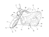
図1から図5に、本発明の一実施形態を示している。図中、1は二輪車、2は二輪車用のカバーを示している。 1 to 5 show an embodiment of the present invention. In the figure, reference numeral 1 denotes a motorcycle, and 2 denotes a cover for a motorcycle.
この実施形態では、二輪車1として、いわゆるネイキッドタイプと呼ばれるものが例示されている。 In this embodiment, what is called a so-called naked type is illustrated as the two-wheeled vehicle 1.
カバー2は、分離されているフロント部3とリア部4とを組み合わせた構成、つまりツーピース構造になっている。フロント部3とリア部4とは、二輪車1の前後方向の所定領域でオーバーラップするように設定されている。
The
フロント部3は、図1に示すように、その後部および下部が開放されているとともに、前部が二輪車1の前輪11に引っ掛けられるような袋形状に形成されていて、二輪車1において前輪11からシート14の前端(燃料タンク13の後端)に至るまでの領域を覆うような寸法に形成されている。
As shown in FIG. 1, the
フロント部3の前部は、前から後に向かって斜め上向きに傾斜した形状になっていて、その最上位置からさらに後に向かって下向きに傾斜した形状になっている。
The front part of the
このフロント部3の前下部には、当該前下部を前輪11の前下側部位の外形に倣う形状にするための絞り部31が設けられている。この前下部には不図示の前輪ロック部材(チェーン、U字形ロックあるいはリンク連結部材等)を挿通するための鍵孔ベルト32が設けられている。
The front portion of the
さらに、フロント部3には、それを二輪車1に装着した状態を保持するための固定手段(符号省略)が設けられている。この固定手段は、胴部絞りベルト5a、プラグ5b、ソケット5cを含む構成になっている。
Furthermore, the
胴部絞りベルト5aは、フロント部3において前開放部分の周縁に取り付けられており、二輪車1のエンジン15の下側に巻き掛けられるものである。
The
プラグ5bおよびソケット5cは、ワンタッチで連結または連結解除されるように構成されたものであって、公知の汎用品とされているので、その詳細な説明は割愛する。
Since the
プラグ5bは、胴部絞りベルト5aの左端寄りの所定位置に取り付けられており、また、ソケット5cは、胴部絞りベルト5aの右端に取り付けられている。なお、プラグ5bは、胴部絞りベルト5aの左端側に対する取り付け位置を任意に変更できるように構成されている。
The
そして、プラグ5bを二輪車1の前輪11と後輪12との間(エンジン15)の下部空間に二輪車1の幅方向一方(左)から幅方向他方(右)へ向けて差し入れて、ソケット5cに近づけて連結すると、胴部絞りベルト5aがエンジン15の下側部位に巻き掛けられる状態になる。これにより、フロント部3が二輪車1に装着された状態で保持される。
Then, the
リア部4は、図1および図3に示すように、その前部および下部が開放されているとともに、後部が二輪車1の後輪12に引っ掛けられるような袋形状に形成されていて、二輪車1において後輪12からシート14を経てフロントフォーク17の手前に至るまでの領域を覆うような寸法に形成されている。
As shown in FIGS. 1 and 3, the
このリア部4は、全体的に見て横長の長方体形状に形成されている。このリア部4の前端側は、前から後に向かって斜め上向きに傾斜した形状になっている。
The
このリア部4の左側構成面45における前後方向中間部位の下側には二輪車1のサイドスタンド16を外へ突き出せるようにするためのスタンド孔41が設けられている。また、左側構成面45の後寄りの下部には不図示の後輪ロック部材(チェーン、U字形ロックあるいはリンク連結部材等)を挿通するための鍵孔42が設けられている。さらに、左側構成面45および右側構成面46の各後下部には、当該各後下部およびそれらで挟まれる部位を後輪12の後下側部位の外形に倣う形状にするための絞り部43,44が設けられている。右側構成面46の絞り部44の下端側には、前記後輪ロック部材を挿通するための鍵孔47が設けられている。
A
そして、リア部4には、それを二輪車1に装着した状態を保持するための固定手段(符号省略)が設けられている。この固定手段は、上側のプラグ6aおよびソケット6bと、下側のプラグ7aおよびソケット7bとを含む構成になっている。
The
上側のプラグ6aおよびソケット6bと、下側のプラグ7aおよびソケット7bとは、それぞれ互いにワンタッチで連結または連結解除されるように構成されたものであって、公知の汎用品とされているので、その詳細な説明は割愛する。
The
上側のプラグ6aは、リア部4の左側構成面45の前斜辺212の長手方向中間部位に取り付けられており、また、上側のソケット6bは、リア部4の右側構成面46の前斜辺213の長手方向中間部位に取り付けられている。
The
具体的には、リア部4の前開放部分の長手方向中間部位に長手方向中間部位が縫合されたベルト6cの左端寄りの所定位置に上側のプラグ6aが取り付けられており、また、ベルト6cの右端に上側のソケット6bが取り付けられている。なお、上側のプラグ6aは、ベルト6cの左端側に対する取り付け位置を任意に変更できるように構成されている。そして、上側のプラグ6aとソケット6bとを、フロントフォーク17の長手方向中間部位の前方で連結する。
Specifically, the
下側のプラグ7aは、リア部4の左側の前斜辺212の下側に一端側が縫合された長尺ベルト7cの自由端寄りの所定位置に取り付けられている。また、下側のソケット7bは、リア部4の右側の前斜辺213の下側に短尺ベルト7dの自由端に取り付けられている。なお、下側のプラグ7aは、長尺ベルト7cの自由端側に対する取り付け位置を任意に変更できるように構成されている。そして、下側のプラグ7aとソケット7bを、前輪11の前下部の前方で連結する。
The
このような上下のプラグ6a,7aおよびソケット6b,7bにより、リア部4が二輪車1に装着された状態で保持される。
By such upper and
なお、前記したフロント部3およびリア部4の布生地としては、柔軟性及び透湿防水性を有する材料(例えばポリエステル樹脂、あるいはポリエステル樹脂に透湿防水性を有する合成樹脂フィルムを重ね合わせたもの等)とされるが、その他に、前記柔軟性及び透湿防水性を有する材料からなる布生地の裏側に、柔軟性、透湿防水性ならびに車体に傷をつけにくい性質を有する材料(例えば合成繊維製の不織布等)からなる裏地を重ね合わせることが可能である。さらに、リア部4において二輪車1のマフラー20が当たる部位には、前記柔軟性及び透湿防水性を有する材料からなる布生地に、耐熱性に優れた布生地(ふっ素系樹脂の織布等)を貼り合わせることも可能である。
The cloth material of the
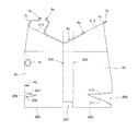
このようなフロント部3およびリア部4は、共に、図4および図5に示すような適宜の布生地を裁縫することにより製作される。
Both the
具体的に、フロント部3の製作手順を説明する。まず、図4に示す前辺101の上下方向(長手方向)の中間点102と中間切り欠き103の最深位置104とを結ぶ仮想直線からなる折り目線105を山折りすることにより、当該折り目線105よりも上側の面と下側の面とを重ね合わせる。これにより、前記下側の面が縫製後の左側構成面34となり、前記上側の面が縫製後の右側構成面35となる。
Specifically, the manufacturing procedure of the
この状態において、左側構成面34の前端と右側構成面35の前端とを重ね合わせて、この重ね合わせ部位を縫合するとともに、中間切り欠き103の片半分領域の内縁106と残り片半分領域の内縁107とを重ね合わせて、この重ね合わせ部位を縫合する。
In this state, the front end of the left
続いて、図4に示す下側切り欠き108の片半分領域の内縁109と残り片半分領域の内縁110とを重ね合わせて、この重ね合わせ部位を縫合する。さらに、図3に示す後下辺111に別体の布生地112を縫合して継ぎ足す。
Subsequently, the
この後、左側構成面34において中間切り欠き103に隣り合う後斜辺113と、右側構成面35において中間切り欠き103に隣り合う後斜辺114と、前記継ぎ足し用の布生地38の自由端縁とに対して胴部絞りベルト5aの長手方向中間部位を縫合するとともに、当該胴部絞りベルト5aの左側部位および右側部位を通すための輪状のベルト通し33を縫合する。この段階では、胴部絞りベルト5aの左端寄りの所定位置にプラグ5bが取り付けられていて、胴部絞りベルト5aの右端にソケット5cが縫合されているものとする。
Thereafter, the
次に、リア部4の製作手順を説明する。まず、図5において、下側(縫製後の後側)に設けられている凹状切り欠き201の左辺および右辺にそれぞれ沿う位置で上下方向に延長する仮想直線からなる折り目線202,203をそれぞれ山折りする。
Next, the manufacturing procedure of the
この状態では、当該2つの折り目線202,203のうちの左側の折り目線202よりも左側の面が縫製後の左側構成面45となり、右側の折り目線203よりも右側の面が縫製後の右側構成面46となる。
In this state, the left side surface of the two
この状態において、左側構成面45の後辺204と右側構成面46の後辺205とを重ね合わせて、この重ね合わせ部位を縫合するとともに、前記後辺204の右側部位と前記後辺205の左側部位とを凹状切り欠き201の内縁に重ね合わせて、この重ね合わせ部位を縫合する。
In this state, the
続いて、左側構成面45の切り欠き206の前半分領域の内縁207と後半分領域の内縁208とを重ね合わせて、この重ね合わせ部位を縫合することにより、絞り部43を作る。一方、右側構成面46の切り欠き209の前半分領域の内縁210と後半分領域の内縁211とを重ね合わせて、この重ね合わせ部位を縫合することにより、絞り部44を作る。なお、右側構成面46の切り欠き209の内縁210,211の重ね合わせ部分については、部分的に縫合しないようにすることによって、鍵孔47を作るようにしている。
Subsequently, the
この後、左側の前斜辺212から右側の前斜辺213に跨る領域にベルト6cの長手方向中間部位を縫合する。この段階では、ベルト6cの左端寄りの所定位置にプラグ6aが取り付けられていて、ベルト6cの右端にソケット6bが取り付けられているものとする。
Thereafter, the intermediate portion in the longitudinal direction of the
さらに、左側の前斜辺212の左端に長尺ベルト7cの一端側を縫合するとともに、右側の前斜辺213の右端に短尺ベルト7dの一端側を縫合する。この段階では、長尺ベルト7cの自由端寄りの所定位置にプラグ7aが取り付けられていて、短尺ベルト7dの自由端にソケット7bが縫合されているものとする。
Further, one end side of the
次に、上記したフロント部3とリア部4を二輪車1に装着する手順を説明する。
Next, a procedure for mounting the
まず、準備段階として、二輪車1のハンドル18を左側に目一杯に動かすことによりハンドルロックできる状態にしておいて、サイドスタンド16を使って左側に傾いた姿勢にする。
First, as a preparatory stage, the
このような姿勢の二輪車1の後輪12側からリア部4の前開放部分を被せることにより、リア部4の絞り部43,44を後輪12の後下側に引っ掛けるようにしながら、後輪12からシート14を経てエンジン15に至るまでの領域を覆う状態にする。
By covering the front opening portion of the
この後、二輪車1を直立する姿勢にして、二輪車1のサイドスタンド16をリア部4のスタンド孔41内に差し入れ、それから二輪車1を左側に傾いた姿勢に戻す。なお、前記準備段階において、二輪車1をそのセンタースタンド(図示省略)を使って直立姿勢にする場合には、サイドスタンド16をスタンド孔41内に差し入れるための動作は不要になる。
Thereafter, the two-wheeled vehicle 1 is brought into an upright posture, the side stand 16 of the two-wheeled vehicle 1 is inserted into the
この状態において、リア部4の上側のプラグ6aを二輪車1の2本のフロントフォーク17の左外側から前方に回り込ませるとともに右外側から後方に引き寄せて、ソケット6bに近づけて連結する。これにより、図3に示すように、ベルト6cがフロントフォーク17の長手方向中間部位に巻き掛けられるようになる。
In this state, the
続いて、下側のプラグ7aを二輪車1の前輪11の前下部の左側から前方に回り込ませるとともに右側から後方に引き寄せて、下側のソケット7bに近づけて連結する。これにより、図1に示すように、長尺ベルト7cと短尺ベルト7dとが前輪11の前下部に巻き付けられるようになる。
Subsequently, the
このようにした結果、図3に示すように、リア部4において左側構成面34と右側構成面35とがエンジン15から後輪12に至るまでの二輪車1の側面領域に密着された状態になる。この状態では、リア部4が前後左右のいずれの方向に引っ張られても外れなくなる。
As a result, as shown in FIG. 3, in the
そして、二輪車1の前輪11側からフロント部3の後開放部分を被せることにより、フロント部3の絞り部31を前輪11の前下側に引っ掛けるようにしながら、ハンドル18から燃料タンク13の後端に至るまでの領域を覆う状態にする。このとき、フロント部3の最上部がハンドル18の右側バックミラー19の上端に引っ掛かった状態になる。
Then, by covering the rear opening portion of the
この状態において、フロント部3のプラグ5bを二輪車1の前輪11と後輪12との間(エンジン15)の下部空間に二輪車1の左側から右側へ向けて差し入れて、ソケット5cに近づけて連結する。
In this state, the
これにより、胴部絞りベルト5aがエンジン15の下側部位に巻き掛けられるようになる。この状態では、フロント部3の左側構成面34および右側構成面35が前輪11に密着されるとともにリア部4の左側構成面45および右側構成面46の前側領域に密着されるようになるので、フロント部3が前後左右のいずれの方向に引っ張られても外れなくなる。
As a result, the
このようにして二輪車1にフロント部3およびリア部4を装着すると、図1に示すように、フロント部3とリア部4とが二輪車1の前後方向所定領域でオーバーラップする状態になって二輪車1の前後方向全域を覆うようになるとともに、フロント部3およびリア部4の左側構成面34,45と右側構成面35,46とが二輪車1の前後方向全域に密着する状態になる。
When the
これにより、二輪車1が雨や風等に曝されなくなるというカバー2本来の保護機能を確実に確保できるようになるとともに、フロント部3およびリア部4が雨や風等によりばたつくことを抑制できるとともに外れることを防止できるようになる。その他、二輪車1の前後方向全域が隠されることになるので、二輪車1の姿を外側から認識できなくなるなど、盗難防止に役立つようになる。
As a result, the original protective function of the
ところで、フロント部3およびリア部4を二輪車1に装着した状態では、前記した不図示の前輪ロック部材や後輪ロック部材を装着することが可能であるが、それらの装着動作については、一般的なワンピースタイプのカバーのそれと同様であるので、ここでの説明は割愛する。
By the way, in the state where the
そして、上記フロント部3およびリア部4を取り外す場合には、フロント部3のプラグ5bをソケット5cから離脱させておいて、フロント部3の最上部を斜め上向きにかつ前方に引っ張ることで、比較的簡単に外すことが可能になる。
When removing the
また、リア部4についても、下側のプラグ7aをソケット7bから離脱させるとともに、上側のプラグ6aをソケット6bから離脱させておいて、リア部4の前上側を斜め上向きにかつ後方に引っ張ることで、比較的簡単に外すことが可能になる。
Also, with respect to the
以上説明したように本発明を適用した実施形態では、カバー2をフロント部3とリア部4との2つにセパレートしているから、二輪車1に装着するときに、一人でも比較的簡単に装着することが可能になる。そのことに伴い、フロント部3およびリア部4をその二輪車1に比較的タイトにフィットするスリムな形状にすることが可能になる。このようにスリムな形状にできることに伴い、二輪車1への装着状態において、雨や風等によってフロント部3およびリア部4がばたつくことを抑制できるとともに外れることを防止できるようになる。
As described above, in the embodiment to which the present invention is applied, since the
このようなことから、本発明を適用した実施形態のカバー2は、二輪車1に比較的タイトにフィットするスリムな形状にできるようにしながら、二輪車1に1人で比較的簡単に装着することが可能になる。
For this reason, the
なお、本発明は、上記実施形態のみに限定されるものではなく、特許請求の範囲内および当該範囲と均等の範囲内で適宜に変更することが可能である。 In addition, this invention is not limited only to the said embodiment, It can change suitably in the range equivalent to the claim and the said range.
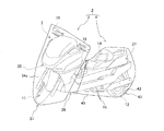
(1)図6から図10には、スクータータイプと呼ばれる二輪車1に適したカバー2を例に挙げている。
(1) In FIGS. 6 to 10, a
このカバー2についても、分離されているフロント部3とリア部4とを組み合わせたツーピース構造になっている。フロント部3とリア部4とは、二輪車1の前後方向の所定領域でオーバーラップせずに離隔するように設定されている。
The
フロント部3は、図6に示すように、その後部および下部が開放されているとともに、前部が二輪車1の前輪11に引っ掛けられるような袋形状に形成されていて、二輪車1において前輪11からフロントカウル25およびセンターカウル26の前後方向の中間部位に至るまでの領域を覆うような寸法に形成されている。
As shown in FIG. 6, the
このフロント部3は、全体的に縦長の長方体形状に形成されている。フロント部3の前部は、前から後に向かって斜め上向きに傾斜した形状になっていて、その最上位置からさらに後に向かって下向きに傾斜した形状になっている。
The
このフロント部3の前下部は、前輪11の前下側部位の外形に倣う形状に縫製されていて、この前下部には不図示の前輪ロック部材(チェーン、U字形ロックあるいはリンク連結部材等)を挿通するための鍵孔ベルト32が設けられている。また、フロント部3の後側には、前開放部分を拡大するためのスライドファスナー36が設けられている。
The front lower portion of the
さらに、フロント部3には、それを二輪車1に装着した状態を保持するための固定手段(符号省略)が設けられている。この固定手段は、プラグ8a、ソケット8bを含む構成になっている。
Furthermore, the
プラグ8aおよびソケット8bは、互いにワンタッチで連結または連結解除されるように構成されたものであって、公知の汎用品とされているので、その詳細な説明は割愛する。
The
プラグ8aは、フロント部3の後右下部に一端側が縫合された長尺ベルト8cの自由端寄りの任意の位置に取り付けられている。また、ソケット8bは、フロント部3の後左下部に一端側が縫合された短尺ベルト8dの自由端に取り付けられている。なお、プラグ8aは、長尺ベルト8cの自由端側に対する取り付け位置を任意に変更できるように構成されている。
The
そして、プラグ8aとソケット8bをセンターカウル26の下側で連結すると、長尺ベルト8cと短尺ベルト8dとがセンターカウル26の下側に巻き付けられる状態になる。これにより、フロント部3が二輪車1に装着された状態で保持される。
When the
リア部4は、図7および図8に示すように、その前部および下部が開放されているとともに、後部が二輪車1の後輪12に引っ掛けられるような袋形状に形成されていて、二輪車1においてリアカウル27からシート14の前端に至るまでの領域を覆うような寸法に形成されている。
As shown in FIGS. 7 and 8, the
このリア部4は、全体的に見て横長の長方体形状に形成されている。このリア部4の前端側は、前から後に向かって斜め上向きに傾斜した形状になっている。
The
このリア部4の左側構成面45における前後方向中間部位の下側には二輪車1のサイドスタンド16を外へ突き出せるようにするためのスタンド孔41が設けられている。また、左側構成面45の後寄りの下部には不図示の後輪ロック部材(チェーン、U字形ロックあるいはリンク連結部材等)を挿通するための鍵孔42が設けられている。さらに、左側構成面45および右側構成面46の各後下部は、後輪12の後下側部位の外形に倣う形状に縫製されている。左側構成面45の後下端と右側構成面46の後下端とには、それぞれ前記後輪ロック部材を挿通するための鍵孔42,47が設けられている。
A
そして、リア部4には、それを二輪車1に装着した状態を保持するための固定手段(符号省略)が設けられている。この固定手段は、プラグ9a、ソケット9bを含む構成になっている。
The
プラグ9aおよびソケット9bは、ワンタッチで連結または連結解除されるように構成されたものであって、公知の汎用品とされているので、その詳細な説明は割愛する。
The
プラグ9aは、リア部4の前開放部分の右下側に一端側が縫合された長尺ベルト9cの自由端寄りの任意の位置に取り付けられている。ソケット9bは、リア部4の前開放部分の左下側に一端側が縫合された短尺ベルト9dの自由端に取り付けられている。なお、プラグ9aは、長尺ベルト9cの自由端側に対する取り付け位置を任意に変更できるように構成されている。
The
そして、プラグ9aとソケット9bとを、センターカウル26の下側で連結すると、長尺ベルト9cと短尺ベルト9dとがセンターカウル26の下側に巻き付けられる状態になる。これにより、リア部4が二輪車1に装着された状態で保持されることになる。
When the
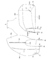
このようなフロント部3およびリア部4は、図9および図10に示すような適宜の布生地を裁縫することにより製作される。
Such a
具体的に、フロント部3の製作手順を説明する。まず、図9に示す左辺301の長手方向中間点302と右辺303の長手方向中間点304とを結ぶ仮想直線からなる折り目線305を山折りすることにより、当該折り目線305よりも左側の面と右側の面とを重ね合わせる。これにより、前記左側の面が縫製後の前方構成面34aとなり、前記右側の面が縫製後の後方構成面35aとなる。
Specifically, the manufacturing procedure of the
この状態において、前方構成面34aの左側湾曲辺306と後方構成面35aの左側湾曲辺307とを重ね合わせて、この重ね合わせ部位を縫合するとともに、前方構成面34aの右側湾曲辺308と後方構成面35aの右側湾曲辺309とを重ね合わせて、この重ね合わせ部位を縫合する。
In this state, the left
続いて、図9に示す前方切り欠き310において前半分領域の内縁311と後半分領域の内縁312とを重ね合わせて、この重ね合わせ部位を縫合する。
Subsequently, in the
この後、後方切り欠き313における左半分領域の内縁314に短尺ベルト8dの一端側を縫合する一方、後方切り欠き313における右半分領域の内縁315に長尺ベルト8cの一端側を縫合する。この段階では、長尺ベルト8cの自由端寄りの所定位置にプラグ8aが取り付けられていて、短尺ベルト8dの自由端にソケット8bが縫合されているものとする。
Thereafter, one end side of the
次に、リア部4の製作手順を説明する。まず、図10において、左側布生地401(左側構成面45に相当)の右辺402を中央布生地405の左辺406の長手方向中間部位に縫合し、右側布生地408(右側構成面46に相当)の左辺409を中央布生地405の右辺407の長手方向中間部位に縫合する。
Next, the manufacturing procedure of the
続いて、当該中央布生地405の前側約1/3の領域と後側約1/3の領域とを下向きに折り曲げるとともに、左側布生地401および右側布生地408をそれぞれ下向きに折り曲げる。
Subsequently, the front side approximately 1/3 region and the back side approximately 1/3 region of the
この状態において、左側布生地401の前辺403と中央布生地405の左辺406における前側約1/3の領域とを縫合するとともに、右側布生地408の前辺410と中央布生地405の右辺407において前側約1/3の領域とを縫合する。
In this state, the
さらに、左側布生地401の後辺404と中央布生地405の左辺406における後側約1/3の領域とを縫合するとともに、右側布生地408の後辺411と中央布生地405の右辺407における後側約1/3の領域とを縫合する。
Further, the
なお、左側布生地401の後辺404の左端側と中央布生地405の左辺406の下端側とを部分的に縫合しないようにすることによって、鍵孔42を作るようにしている。また、右側布生地408の後辺411の右端側と中央布生地405の右辺407の下端側とを部分的に縫合しないようにすることによって、鍵孔47を作るようにしている。
Note that the
続いて、中央布生地405の切り欠き412の左半分領域の内縁413と右半分領域の内縁414とを重ね合わせて、この重ね合わせ部位を縫合することにより、リア部4の後下部を幅狭にするとともに前方向に湾曲させる。
Subsequently, the inner edge 413 of the left half region and the inner edge 414 of the right half region of the
この後、左側布生地401の前辺403の左端側に短尺ベルト9dの一端側を縫合し、さらに、右側布生地408の前辺410の右端側に長尺ベルト9cの一端側を縫合する。この段階では、長尺ベルト9cの自由端寄りの所定位置にプラグ9aが取り付けられていて、短尺ベルト9dの自由端にソケット9bが縫合されているものとする。
Thereafter, one end side of the
次に、上記したフロント部3とリア部4を二輪車1に装着する手順を説明する。
Next, a procedure for mounting the
まず、準備段階として、二輪車1のハンドル18を左側に目一杯に動かすことによりハンドルロックできる状態にしておいて、サイドスタンド16で左側に傾いた姿勢にする。
First, as a preparation stage, the
このような姿勢の二輪車1の後輪12側からリア部4の前開放部分を被せることにより、リア部4の後下部を後輪12の後下側に引っ掛けるようにしながら、後輪12からシート14の前端に至るまでの領域を覆う状態にする。
By covering the front open part of the
この状態において、リア部4のプラグ9aを二輪車1のセンターカウル26の下部空間に二輪車1の右側から左側へ向けて差し入れて、ソケット9bに近づけて連結する。
In this state, the
これにより、図8に示すように、長尺ベルト9cと短尺ベルト9dとがセンターカウル26の下側に巻き付けられるとともに、リア部4において左側構成面45の前下部と右側構成面46の前下部とがセンターカウル26の下側に密着された状態になる。この状態では、リア部4が前後左右のいずれの方向に引っ張られても外れなくなる。
As a result, as shown in FIG. 8, the
そして、二輪車1の前輪11側からフロント部3の後開放部分を被せることにより、フロント部3の前下部を前輪11の前下側に引っ掛けるようにしながら、フロントカウル25からセンターカウル26の前後方向中間部位に至るまでの領域を覆う状態にして、スライドファスナー36を閉じる。このとき、フロント部3の最上部がハンドル18の右側バックミラー19の上端に引っ掛かった状態になる。
Then, by covering the rear opening portion of the
この状態において、フロント部3のプラグ8aを二輪車1のセンターカウル26の前方下部空間に二輪車1の左側から右側へ向けて差し入れて、ソケット8bに近づけて連結する。
In this state, the
これにより、図6に示すように、長尺ベルト8cと短尺ベルト8dとがセンターカウル26の下側に巻き付けられるとともに、フロント部3の後左下部とフロント部3の後右下部とがセンターカウル26の下側に密着する状態になる。この状態では、フロント部3が前後左右のいずれの方向に引っ張られても外れなくなる。
As a result, as shown in FIG. 6, the
このようにして二輪車1にフロント部3およびリア部4を装着すると、フロント部3およびリア部4が雨や風等によりばたつくことを抑制できるとともに外れることを防止できるようになる。
When the
ところで、フロント部3およびリア部4を二輪車1に装着した状態では、前記した不図示の前輪ロック部材や後輪ロック部材を装着することが可能であるが、それらの装着動作については、一般的なワンピースタイプのカバーのそれと同様であるので、ここでの説明は割愛する。
By the way, in the state where the
そして、フロント部3およびリア部4を二輪車1から取り外す場合には、フロント部3のプラグ8aをソケット8bから離脱させておいて、フロント部3の最上部を斜め上向きにかつ前方に引っ張ることで、比較的簡単に外すことが可能になる。
And when removing the
また、リア部4についても、プラグ9aをソケット9bから離脱させておいて、リア部4の前上側を斜め上向きにかつ後方に引っ張ることで、比較的簡単に外すことが可能になる。
Also, the
以上説明したように、この実施形態においても、上記実施形態と同様の作用、効果が得られる。 As described above, also in this embodiment, the same operations and effects as in the above embodiment can be obtained.
但し、この実施形態では、二輪車1のセンターカウル26の前後方向所定領域をフロント部3およびリア部4で意図的に覆うようにしていない。このようにしている理由を説明する。二輪車1がスクータータイプである関係より、仮にフロント部3およびリア部4をセンターカウル26の前後方向所定領域でオーバーラップさせるようにしていると、雨が降った後で前記オーバーラップ領域の上側に雨水が溜まることが予想される。このような雨水が溜まることを防止するために、フロント部3およびリア部4を意図的にオーバーラップさせずに、センターカウル26の前後方向所定領域を露呈させるようにしているのである。
However, in this embodiment, a predetermined region in the front-rear direction of the
(2)上記実施形態に示した固定手段は、一実施形態であって、これのみに限定されるものではなく、例えば面ファスナー、あるいはそれ以外の公知の部材等とすることが可能である。 (2) The fixing means shown in the above embodiment is an embodiment and is not limited to this. For example, a hook-and-loop fastener or other known members can be used.
本発明は、二輪車用のカバーに好適に利用することが可能である。 The present invention can be suitably used for a cover for a motorcycle.
1 二輪車
11 前輪
12 後輪
14 シート
17 フロントフォーク
2 カバー
3 フロント部
31 絞り部
34 左側構成面
35 右側構成面
4 リア部
43 左側の絞り部
44 右側の絞り部
45 左側構成面
46 右側構成面
5a 胴部絞りベルト
5b プラグ
5c ソケット
6a 上側のプラグ
6b 上側のソケット
6c ベルト
7a 下側のプラグ
7b 下側のソケット
7c 長尺ベルト
7d 短尺ベルト
1 motorcycle
11 Front wheels
12 Rear wheel
14 seats
17 Front fork
2 Cover
3 Front part
31 Aperture
34 Left side
35 Right side
4 Rear part
43 Left aperture
44 Right diaphragm
45 left side
46 Right side
5a Torque belt
5b plug
5c socket
6a Upper plug
6b Upper socket
6c belt
7a Lower plug
7b Lower socket
7c Long belt
7d short belt
本発明に係る二輪車用のカバーは、二輪車の前輪側を覆うためのフロント部と、前記二輪車の後輪側を覆うためのリア部とを含み、前記フロント部と前記リア部とは、前記二輪車の前後方向の所定領域でオーバーラップするように設定されており、前記フロント部および前記リア部には、それぞれ個別に前記二輪車に装着した状態を保持するための固定手段が設けられており、前記フロント部は、その後部および下部が開放されているとともに、前部が前記二輪車の前輪に引っ掛けられるような袋形状に形成され、かつ前記前輪からシートの前端に至るまでの領域を覆うような寸法に設定されており、前記リア部は、その前部および下部が開放されているとともに、後部が前記二輪車の後輪に引っ掛けられるような袋形状に形成され、かつ前記後輪からシートを経てフロントフォークの手前に至るまでの領域を覆うような寸法に設定されており、前記リア部の固定手段は、当該リア部の左側構成面または右側構成面の前端の上下方向中間部位に設けられる上側のプラグと、前記右側構成面または左側構成面の前端の上下方向中間部位に設けられかつ前記上側のプラグに連結可能とされる上側のソケットと、前記左側構成面または右側構成面の前端の下側に設けられる下側のプラグと、前記右側構成面または左側構成面の前端の下側に設けられかつ前記下側のプラグに連結可能とされる下側のソケットとを含み、かつ、前記固定手段の使用時には、前記上側のプラグまたはソケットを前記二輪車のフロントフォークの左右一方から前方に回り込ませて左右他方から後方に引き寄せて前記上側のソケットまたはプラグに近づけて連結することにより、前記左側構成面の前端の上下方向中間部位と前記右側構成面の前端の上下方向中間部位とを前記フロントフォークの長手方向中間部位に巻き付ける状態にし、前記下側のプラグまたはソケットを前記二輪車の前輪の前下部の左右一方から前方に回り込ませて左右他方から後方に引き寄せて前記下側のソケットまたはプラグに近づけて連結することにより、前記左側構成面の前下部と前記右側構成面の前下部とを前記前輪の前下部に巻き付ける状態にする、ことを特徴としている。 A cover for a motorcycle according to the present invention includes a front part for covering the front wheel side of the two-wheeled vehicle and a rear part for covering the rear wheel side of the two-wheeled vehicle, and the front part and the rear part are the two-wheeled vehicle. is set so as to overlap at a predetermined region in the front-rear direction of the front portion and the rear portion is fixed means for holding being attached individually to the two-wheel vehicle, respectively is provided, said The front portion has a rear portion and a lower portion that are open, the front portion is formed in a bag shape that is hooked on the front wheel of the two-wheeled vehicle, and covers a region from the front wheel to the front end of the seat. The rear portion is formed in a bag shape such that a front portion and a lower portion thereof are opened and a rear portion is hooked on a rear wheel of the two-wheeled vehicle. The dimension of the rear part is fixed so as to cover the area from the rear wheel through the seat to the front fork, and the fixing means of the rear part is the vertical direction of the left side configuration surface of the rear part or the front end of the right side configuration surface An upper plug provided at an intermediate portion, an upper socket provided at an intermediate portion in a vertical direction at a front end of the right side configuration surface or the left side configuration surface, and connectable to the upper plug; and the left side configuration surface or the right side A lower plug provided below the front end of the component surface, and a lower socket provided below the front end of the right component surface or the left component surface and connectable to the lower plug. In addition, when the fixing means is used, the upper plug or socket is moved forward from one of the left and right sides of the front fork of the two-wheeled vehicle and pulled backward from the other left and right. By connecting close to the upper socket or plug, the intermediate portion in the vertical direction at the front end of the left component surface and the intermediate portion in the vertical direction at the front end of the right component surface are wound around the intermediate portion in the longitudinal direction of the front fork. The lower plug or socket is moved forward from the left and right ones of the front lower part of the front wheel of the two-wheeled vehicle and pulled backward from the other left and right to be connected to the lower socket or plug, thereby connecting the left side structure. you state of winding a front lower portion of the right construction surface and the front lower surface in a front lower portion of the front wheel, is characterized in that.
このようにスリムな形状にできることに加えて、前記フロント部および前記リア部を二輪車に装着した状態を前記固定手段により保持できるようにしているから、二輪車に装着した前記フロント部および前記リア部が雨や風等によってばたつくことを抑制できるとともに外れることを防止できるようになる。しかも、上記リア部の固定手段が前記リア部の左側構成面と右側構成面とを二輪車に密着させた状態にしやすくなるので、二輪車に装着したリア部が雨や風等によりばたつくことを抑制する効果ならびに外れることを防止する効果が向上する。 In addition to being able to have such a slim shape, the state in which the front part and the rear part are attached to the motorcycle can be held by the fixing means, so that the front part and the rear part attached to the motorcycle are Fluttering due to rain, wind, etc. can be suppressed and it can be prevented from coming off. In addition, since the fixing means for the rear part can easily bring the left and right constituent surfaces of the rear part into close contact with the two-wheeled vehicle, the rear part attached to the two-wheeled vehicle is prevented from fluttering due to rain or wind. The effect and the effect of preventing detachment are improved.
また、上記のように前記フロント部と前記リア部とを前記二輪車の前後方向の所定領域でオーバーラップさせていれば、前記フロント部と前記リア部とを前記二輪車に装着したときに、例えば前記フロント部と前記リア部とが二輪車の前後方向所定領域で重なり合うことになって、二輪車の前後方向全域を覆うようになる。 Further, as described above, if the front part and the rear part overlap each other in a predetermined region in the front-rear direction of the two-wheeled vehicle , when the front part and the rear part are mounted on the two-wheeled vehicle, for example, The front portion and the rear portion overlap each other in a predetermined region in the front-rear direction of the two-wheeled vehicle so as to cover the entire front-rear direction of the two-wheeled vehicle.
Claims (5)
前記フロント部および前記リア部には、それぞれ個別に前記二輪車に装着した状態を保持するための固定手段が設けられている、ことを特徴とする二輪車用のカバー。 Including a front part for covering the front wheel side of the motorcycle, and a rear part for covering the rear wheel side of the motorcycle,
A cover for a motorcycle, wherein the front portion and the rear portion are each provided with a fixing means for maintaining a state of being mounted on the motorcycle individually.
前記フロント部と前記リア部とは、前記二輪車の前後方向の所定領域でオーバーラップするように設定されている、ことを特徴とする二輪車用のカバー。 The motorcycle cover according to claim 1,
The cover for a two-wheeled vehicle, wherein the front part and the rear part are set to overlap in a predetermined region in the front-rear direction of the two-wheeled vehicle.
前記フロント部は、その後部および下部が開放されているとともに、前部が前記二輪車の前輪に引っ掛けられるような袋形状に形成され、かつ前記前輪からシートの前端に至るまでの領域を覆うような寸法に設定されており、
前記リア部は、その前部および下部が開放されているとともに、後部が前記二輪車の後輪に引っ掛けられるような袋形状に形成され、かつ前記後輪からシートを経てフロントフォークの手前に至るまでの領域を覆うような寸法に設定されている、ことを特徴とする二輪車用のカバー。 The cover for a motorcycle according to claim 2,
The front portion has a rear portion and a lower portion opened, and a front portion is formed in a bag shape that is hooked on a front wheel of the two-wheeled vehicle, and covers a region from the front wheel to the front end of the seat. Set to dimensions,
The rear part is formed in a bag shape such that the front part and the lower part are opened and the rear part is hooked on the rear wheel of the two-wheeled vehicle, and from the rear wheel through the seat to the front fork. A cover for a two-wheeled vehicle, characterized in that the size is set to cover the area of the motorcycle.
前記フロント部の固定手段は、前記後部の開放部分に設けられる胴部絞りベルトと、この胴部絞りベルトの一端側と他端側とを連結可能に当該一端側および他端側に設けられるプラグおよびソケットとを含み、
かつ、前記固定手段の使用時には、前記プラグまたはソケットを前記二輪車の前輪と後輪との間の下部空間に前記二輪車の幅方向一方から他方へ向けて差し入れて前記ソケットまたはプラグに近づけて連結することにより、前記胴部絞りベルトを前記二輪車の前輪と後輪との間に巻き掛ける状態にする、ことを特徴とする二輪車用のカバー。 The cover for a motorcycle according to claim 3,
The fixing means of the front part includes a body squeezing belt provided at an open portion of the rear part, and a plug provided on the one end side and the other end side so as to connect one end side and the other end side of the body squeezing belt. And a socket,
When the fixing means is used, the plug or socket is inserted into the lower space between the front wheel and the rear wheel of the two-wheel vehicle from one side to the other in the width direction of the two-wheel vehicle and connected close to the socket or plug. Thus, the two-wheeled vehicle cover is characterized in that the trunk diaphragm belt is wound between a front wheel and a rear wheel of the two-wheeled vehicle.
前記リア部の固定手段は、当該リア部の左側構成面または右側構成面の前端の上下方向中間部位に設けられる上側のプラグと、前記右側構成面または左側構成面の前端の上下方向中間部位に設けられかつ前記上側のプラグに連結可能とされる上側のソケットと、前記左側構成面または右側構成面の前端の下側に設けられる下側のプラグと、前記右側構成面または左側構成面の前端の下側に設けられかつ前記下側のプラグに連結可能とされる下側のソケットとを含み、
かつ、前記固定手段の使用時には、前記上側のプラグまたはソケットを前記二輪車のフロントフォークの左右一方から前方に回り込ませて左右他方から後方に引き寄せて前記上側のソケットまたはプラグに近づけて連結することにより、前記左側構成面の前端の上下方向中間部位と前記右側構成面の前端の上下方向中間部位とを前記フロントフォークの長手方向中間部位に巻き付ける状態にし、
前記下側のプラグまたはソケットを前記二輪車の前輪の前下部の左右一方から前方に回り込ませて左右他方から後方に引き寄せて前記下側のソケットまたはプラグに近づけて連結することにより、前記左側構成面の前下部と前記右側構成面の前下部とを前記前輪の前下部に巻き付ける状態にする、ことを特徴とする二輪車用のカバー。 The cover for a motorcycle according to claim 3 or 4,
The rear portion fixing means includes an upper plug provided in a vertical intermediate portion at the front end of the left component surface or right component surface of the rear portion, and a vertical intermediate portion at the front end of the right component surface or left component surface. An upper socket provided and connectable to the upper plug; a lower plug provided below a front end of the left component surface or right component surface; and a front end of the right component surface or left component surface A lower socket provided on the lower side and connectable to the lower plug,
And, when the fixing means is used, the upper plug or socket is turned forward from one of the left and right sides of the front fork of the two-wheeled vehicle, and is pulled backward from the other left and right to be connected close to the upper socket or plug. , In a state where the vertical intermediate portion of the front end of the left component surface and the vertical intermediate portion of the front end of the right component surface are wound around the longitudinal intermediate portion of the front fork,
The lower side plug or socket is moved forward from one of the left and right front lower portions of the front wheel of the two-wheeled vehicle, and drawn backward from the other left and right to be connected to the lower socket or plug, thereby connecting the left side configuration surface. A cover for a two-wheeled vehicle, characterized in that a front lower part of the right side and a front lower part of the right side construction surface are wound around the front lower part of the front wheel.
Priority Applications (1)
| Application Number | Priority Date | Filing Date | Title |
|---|---|---|---|
| JP2016031944A JP6105110B1 (en) | 2016-02-23 | 2016-02-23 | Cover for motorcycle |
Applications Claiming Priority (1)
| Application Number | Priority Date | Filing Date | Title |
|---|---|---|---|
| JP2016031944A JP6105110B1 (en) | 2016-02-23 | 2016-02-23 | Cover for motorcycle |
Publications (2)
| Publication Number | Publication Date |
|---|---|
| JP6105110B1 JP6105110B1 (en) | 2017-03-29 |
| JP2017149209A true JP2017149209A (en) | 2017-08-31 |
Family
ID=59366157
Family Applications (1)
| Application Number | Title | Priority Date | Filing Date |
|---|---|---|---|
| JP2016031944A Expired - Fee Related JP6105110B1 (en) | 2016-02-23 | 2016-02-23 | Cover for motorcycle |
Country Status (1)
| Country | Link |
|---|---|
| JP (1) | JP6105110B1 (en) |
Cited By (1)
| Publication number | Priority date | Publication date | Assignee | Title |
|---|---|---|---|---|
| GB2613006A (en) * | 2021-11-19 | 2023-05-24 | Duraida Ltd | A vehicle cover for protecting a road going vehicle |
Citations (13)
| Publication number | Priority date | Publication date | Assignee | Title |
|---|---|---|---|---|
| JPS4833902Y1 (en) * | 1969-12-10 | 1973-10-15 | ||
| JPS53106956U (en) * | 1977-02-02 | 1978-08-28 | ||
| JPS61191983U (en) * | 1985-05-23 | 1986-11-29 | ||
| JPH0260693U (en) * | 1988-10-27 | 1990-05-07 | ||
| JP3040524U (en) * | 1997-02-14 | 1997-08-26 | 株式会社斉工舎 | Motorcycle cover |
| JPH10152084A (en) * | 1996-11-25 | 1998-06-09 | Paafuekuto Shoji Kk | Cover for motorcycle |
| JP2000219179A (en) * | 1999-01-29 | 2000-08-08 | Aiwa Co Ltd | Bicycle and bicycle cover |
| JP2003081161A (en) * | 2001-09-10 | 2003-03-19 | Wise Gear:Kk | Cover for motorcycle |
| JP3112350U (en) * | 2005-05-09 | 2005-08-11 | 有限会社大久保製作所 | Body cover for motorcycle |
| JP3136242U (en) * | 2007-08-09 | 2007-10-18 | 萩原 喜子 | Body protection cover for motorcycles |
| JP4864601B2 (en) * | 2006-08-12 | 2012-02-01 | 有限会社大久保製作所 | Body cover for motorcycle |
| JP3189859U (en) * | 2014-01-22 | 2014-04-03 | 直子 野村 | Thermal cover for Bike Bear Fuller |
| CN103770870A (en) * | 2012-10-25 | 2014-05-07 | 吴勤堃 | Sunshade and rainshade device for locomotive |
-
2016
- 2016-02-23 JP JP2016031944A patent/JP6105110B1/en not_active Expired - Fee Related
Patent Citations (13)
| Publication number | Priority date | Publication date | Assignee | Title |
|---|---|---|---|---|
| JPS4833902Y1 (en) * | 1969-12-10 | 1973-10-15 | ||
| JPS53106956U (en) * | 1977-02-02 | 1978-08-28 | ||
| JPS61191983U (en) * | 1985-05-23 | 1986-11-29 | ||
| JPH0260693U (en) * | 1988-10-27 | 1990-05-07 | ||
| JPH10152084A (en) * | 1996-11-25 | 1998-06-09 | Paafuekuto Shoji Kk | Cover for motorcycle |
| JP3040524U (en) * | 1997-02-14 | 1997-08-26 | 株式会社斉工舎 | Motorcycle cover |
| JP2000219179A (en) * | 1999-01-29 | 2000-08-08 | Aiwa Co Ltd | Bicycle and bicycle cover |
| JP2003081161A (en) * | 2001-09-10 | 2003-03-19 | Wise Gear:Kk | Cover for motorcycle |
| JP3112350U (en) * | 2005-05-09 | 2005-08-11 | 有限会社大久保製作所 | Body cover for motorcycle |
| JP4864601B2 (en) * | 2006-08-12 | 2012-02-01 | 有限会社大久保製作所 | Body cover for motorcycle |
| JP3136242U (en) * | 2007-08-09 | 2007-10-18 | 萩原 喜子 | Body protection cover for motorcycles |
| CN103770870A (en) * | 2012-10-25 | 2014-05-07 | 吴勤堃 | Sunshade and rainshade device for locomotive |
| JP3189859U (en) * | 2014-01-22 | 2014-04-03 | 直子 野村 | Thermal cover for Bike Bear Fuller |
Cited By (1)
| Publication number | Priority date | Publication date | Assignee | Title |
|---|---|---|---|---|
| GB2613006A (en) * | 2021-11-19 | 2023-05-24 | Duraida Ltd | A vehicle cover for protecting a road going vehicle |
Also Published As
| Publication number | Publication date |
|---|---|
| JP6105110B1 (en) | 2017-03-29 |
Similar Documents
| Publication | Publication Date | Title |
|---|---|---|
| US20090025843A1 (en) | Protective vehicle cover | |
| US11591035B2 (en) | Bicycle cover | |
| US9211929B1 (en) | Protective cover for motorcycle fairing | |
| JP5804657B2 (en) | Front child seat cover | |
| JP6105110B1 (en) | Cover for motorcycle | |
| JP3173532U (en) | Bicycle body cover | |
| JP3192626U (en) | Body cover for motorcycle | |
| JP5118681B2 (en) | Cover sheet for bag with hand | |
| JP4864601B2 (en) | Body cover for motorcycle | |
| JP6074180B2 (en) | Bicycle handle cover | |
| JP2007062437A (en) | Rain cover device for strollers | |
| JP6383513B2 (en) | Body cover for motorcycle | |
| JP3040524U (en) | Motorcycle cover | |
| JP2019064375A (en) | Cover for straddle type vehicle | |
| JP7773775B2 (en) | Motorcycle handlebar cover | |
| JP3183470U (en) | Bicycle cover | |
| JP2020032815A (en) | Rain cover for child seat | |
| JP3124817U (en) | Body cover for bicycles | |
| JP3112350U (en) | Body cover for motorcycle | |
| JP3178602U (en) | Bicycle body cover | |
| JP3187374U (en) | Spare tire cover | |
| JP7812300B2 (en) | Vehicle Cover | |
| JP2005231627A (en) | Body cover for motorcycle | |
| JP3143908U (en) | Bicycle body cover | |
| JP2019098990A (en) | Seat bag and bag fastener for saddle-riding type vehicle |
Legal Events
| Date | Code | Title | Description |
|---|---|---|---|
| A521 | Written amendment |
Free format text: JAPANESE INTERMEDIATE CODE: A523 Effective date: 20170111 |
|
| TRDD | Decision of grant or rejection written | ||
| A01 | Written decision to grant a patent or to grant a registration (utility model) |
Free format text: JAPANESE INTERMEDIATE CODE: A01 Effective date: 20170131 |
|
| A61 | First payment of annual fees (during grant procedure) |
Free format text: JAPANESE INTERMEDIATE CODE: A61 Effective date: 20170301 |
|
| R150 | Certificate of patent or registration of utility model |
Ref document number: 6105110 Country of ref document: JP Free format text: JAPANESE INTERMEDIATE CODE: R150 |
|
| LAPS | Cancellation because of no payment of annual fees |