JP2017158360A - コンバータ用フィルタユニット - Google Patents
コンバータ用フィルタユニット Download PDFInfo
- Publication number
- JP2017158360A JP2017158360A JP2016041065A JP2016041065A JP2017158360A JP 2017158360 A JP2017158360 A JP 2017158360A JP 2016041065 A JP2016041065 A JP 2016041065A JP 2016041065 A JP2016041065 A JP 2016041065A JP 2017158360 A JP2017158360 A JP 2017158360A
- Authority
- JP
- Japan
- Prior art keywords
- flat plate
- filter
- members
- slit
- converter
- Prior art date
- Legal status (The legal status is an assumption and is not a legal conclusion. Google has not performed a legal analysis and makes no representation as to the accuracy of the status listed.)
- Granted
Links
Images



Landscapes
- Rectifiers (AREA)
- Power Conversion In General (AREA)
Abstract
Description
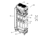
図1〜図9を参照して、本実施形態によるフィルタユニット100の構成について説明する。なお、フィルタユニット100は、特許請求の範囲の「コンバータ用フィルタユニット」の一例である。
まず、図1を参照して、電力変換装置200およびフィルタユニット100の回路構成について説明する。
次に、図2〜図4を参照して、フィルタユニット100の構造について説明する。
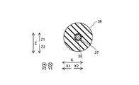
次に、図5〜図9を参照して、フィルタ抵抗部30の詳細な構造について説明する。なお、図6は、互いに隣接するように配置される平板状部材31の模式図であり、互いに隣接する平板状部材31の間隔が、図5に比べて大きく示されている。また、平板状部材31の枚数が、図5に比べて少なく示されている。
本実施形態では、以下のような効果を得ることができる。
なお、今回開示された実施形態は、すべての点で例示であって制限的なものではないと考えられるべきである。本発明の範囲は、上記した実施形態の説明ではなく特許請求の範囲によって示され、さらに特許請求の範囲と均等の意味および範囲内でのすべての変更(変形例)が含まれる。
30 フィルタ抵抗部
31 平板状部材
31a (平板状部材の)端部
31b 長辺
31c 短辺
31d 表面
31e 凹部
32 スリット
32a 開口
33 第1電流経路部
33a (第1電流経路部の)端部
34 第2電流経路部
34a (第2電流経路部の)端部
36 絶縁部材
37 軸部材
40 フィルタコンデンサ
100 フィルタユニット(コンバータ用フィルタユニット)
201 コンバータ部(コンバータ)
220 交流電源(電源)
Claims (9)
- 電源とコンバータとの間に設けられるコンバータ用フィルタユニットであって、
前記電源から供給される電流の高周波成分を除去するためのフィルタリアクトルと、
前記フィルタリアクトルにより除去された高周波成分の電流が通過するフィルタ抵抗部と、
前記フィルタ抵抗部を通過した高周波成分の電流を蓄積するためのフィルタコンデンサとを備え、
前記フィルタ抵抗部は、前記フィルタリアクトルにより除去された高周波成分の電流が通過する平板状部材を含み、
前記平板状部材には、前記平板状部材の端部に開口を有する切欠き状のスリットが設けられている、コンバータ用フィルタユニット。 - 前記平板状部材は、前記スリットが延びる方向と交差する方向の一方側に配置され、前記フィルタリアクトルにより除去された高周波成分の電流が流れ込む第1電流経路部と、前記スリットが延びる方向と交差する方向の他方側に配置され、前記フィルタリアクトルにより除去された高周波成分の電流が流れ出す第2電流経路部とを含む、請求項1に記載のコンバータ用フィルタユニット。
- 前記平板状部材は、複数設けられ、
前記複数の平板状部材は、互いの表面が対向するとともに、前記切欠き状のスリットの開口が同一の方向を向くように隣接して配置されており、
隣接する前記平板状部材のうちの一方の前記平板状部材の前記第2電流経路部の端部と、隣接する前記平板状部材のうちの他方の前記平板状部材の前記第1電流経路部の端部とが電気的に接続されている、請求項2に記載のコンバータ用フィルタユニット。 - 前記平板状部材は、略長方形形状を有し、
前記スリットは、前記略長方形形状の平板状部材の長辺に沿って延びるように設けられている、請求項1〜3のいずれか1項に記載のコンバータ用フィルタユニット。 - 前記スリットは、前記略長方形形状の平板状部材の短辺の略中央部分から、前記長辺に沿って延びるように設けられている、請求項4に記載のコンバータ用フィルタユニット。
- 前記スリットは、前記略長方形形状の平板状部材の一方側の前記短辺から他方側の前記短辺近傍まで、前記長辺に沿って延びるように設けられている、請求項5に記載のコンバータ用フィルタユニット。
- 前記平板状部材は、複数設けられ、
前記複数の平板状部材にそれぞれ設けられる前記スリットの位置は、前記複数の平板状部材において略同一である、請求項1〜6のいずれか1項に記載のコンバータ用フィルタユニット。 - 前記平板状部材は、複数設けられ、
前記複数の平板状部材は、互いの表面が対向するとともに、前記切欠き状のスリットの開口が同一の方向を向くように隣接して配置されており、
前記複数の平板状部材を絶縁するために前記複数の平板状部材の間に配置される複数の絶縁部材と、
前記複数の絶縁部材と、前記複数の平板状部材の前記スリットとを貫通するように配置される軸部材とをさらに備える、請求項1〜7のいずれか1項に記載のコンバータ用フィルタユニット。 - 前記平板状部材の前記スリットには、前記スリットが延びる方向と直交する方向に窪むように、前記軸部材が貫通するための凹部が設けられている、請求項8に記載のコンバータ用フィルタユニット。
Priority Applications (1)
| Application Number | Priority Date | Filing Date | Title |
|---|---|---|---|
| JP2016041065A JP6693177B2 (ja) | 2016-03-03 | 2016-03-03 | コンバータ用フィルタユニット |
Applications Claiming Priority (1)
| Application Number | Priority Date | Filing Date | Title |
|---|---|---|---|
| JP2016041065A JP6693177B2 (ja) | 2016-03-03 | 2016-03-03 | コンバータ用フィルタユニット |
Publications (2)
| Publication Number | Publication Date |
|---|---|
| JP2017158360A true JP2017158360A (ja) | 2017-09-07 |
| JP6693177B2 JP6693177B2 (ja) | 2020-05-13 |
Family
ID=59810466
Family Applications (1)
| Application Number | Title | Priority Date | Filing Date |
|---|---|---|---|
| JP2016041065A Active JP6693177B2 (ja) | 2016-03-03 | 2016-03-03 | コンバータ用フィルタユニット |
Country Status (1)
| Country | Link |
|---|---|
| JP (1) | JP6693177B2 (ja) |
Citations (5)
| Publication number | Priority date | Publication date | Assignee | Title |
|---|---|---|---|---|
| JPH0121523Y2 (ja) * | 1983-05-31 | 1989-06-27 | ||
| JPH0878201A (ja) * | 1994-09-01 | 1996-03-22 | Akashi Denki Kk | 抵抗素子 |
| JPH10284301A (ja) * | 1997-04-07 | 1998-10-23 | Yaskawa Electric Corp | Sf6 ガス封入抵抗器 |
| US5877674A (en) * | 1996-09-12 | 1999-03-02 | Post Glover Resistors Inc. | Resistor with elongated resistor element panels |
| WO2015033710A1 (ja) * | 2013-09-06 | 2015-03-12 | 富士電機株式会社 | フィルタ装置 |
-
2016
- 2016-03-03 JP JP2016041065A patent/JP6693177B2/ja active Active
Patent Citations (5)
| Publication number | Priority date | Publication date | Assignee | Title |
|---|---|---|---|---|
| JPH0121523Y2 (ja) * | 1983-05-31 | 1989-06-27 | ||
| JPH0878201A (ja) * | 1994-09-01 | 1996-03-22 | Akashi Denki Kk | 抵抗素子 |
| US5877674A (en) * | 1996-09-12 | 1999-03-02 | Post Glover Resistors Inc. | Resistor with elongated resistor element panels |
| JPH10284301A (ja) * | 1997-04-07 | 1998-10-23 | Yaskawa Electric Corp | Sf6 ガス封入抵抗器 |
| WO2015033710A1 (ja) * | 2013-09-06 | 2015-03-12 | 富士電機株式会社 | フィルタ装置 |
Also Published As
| Publication number | Publication date |
|---|---|
| JP6693177B2 (ja) | 2020-05-13 |
Similar Documents
| Publication | Publication Date | Title |
|---|---|---|
| JP7133566B2 (ja) | インバータ | |
| US9721719B1 (en) | Coupled inductors with leakage plates, and associated systems and methods | |
| US20190089243A1 (en) | On-vehicle power conversion apparatus | |
| JP7152296B2 (ja) | 電力変換装置、及び高電圧ノイズフィルタ | |
| US8179003B2 (en) | Motor with wire fixing plate | |
| US8421578B2 (en) | Magnetic device and method for generating inductance | |
| JP5338639B2 (ja) | 電力変換装置 | |
| WO2018012059A1 (ja) | 複合平滑インダクタおよび平滑化回路 | |
| US10554123B2 (en) | Power converter with a parallel flat plate conductor electrically connected with a capacitor and a power module | |
| US9548633B2 (en) | Stator of motor having tooth portions with different widths | |
| JP2022521856A (ja) | 多相スイッチングレギュレータ | |
| US9462727B2 (en) | LC filter having a function to cool AC reactor | |
| JP2005176555A (ja) | 電力変換装置 | |
| WO2018189979A1 (ja) | コイル及びそれを用いたモータ | |
| JP2014042377A (ja) | 電源ブスバー及びそれを用いる電力変換装置 | |
| CN104380587B (zh) | 功率转换装置 | |
| JP6693177B2 (ja) | コンバータ用フィルタユニット | |
| JP6314099B2 (ja) | 電力変換装置 | |
| JP6658915B2 (ja) | 電力変換装置 | |
| US11462997B2 (en) | DC to DC converter for a vehicle alternator | |
| JP7276028B2 (ja) | 電力変換装置 | |
| JP5726117B2 (ja) | 電力変換器ユニット及びこれを用いた電力変換装置 | |
| JP6934275B2 (ja) | 電力変換装置 | |
| JP2021182841A (ja) | ノイズフィルタ、電力変換装置 | |
| JP2001086731A (ja) | 電力変換器の主回路構造 |
Legal Events
| Date | Code | Title | Description |
|---|---|---|---|
| A621 | Written request for application examination |
Free format text: JAPANESE INTERMEDIATE CODE: A621 Effective date: 20190214 |
|
| A977 | Report on retrieval |
Free format text: JAPANESE INTERMEDIATE CODE: A971007 Effective date: 20191206 |
|
| A131 | Notification of reasons for refusal |
Free format text: JAPANESE INTERMEDIATE CODE: A131 Effective date: 20191217 |
|
| A521 | Request for written amendment filed |
Free format text: JAPANESE INTERMEDIATE CODE: A523 Effective date: 20200120 |
|
| TRDD | Decision of grant or rejection written | ||
| A01 | Written decision to grant a patent or to grant a registration (utility model) |
Free format text: JAPANESE INTERMEDIATE CODE: A01 Effective date: 20200317 |
|
| A61 | First payment of annual fees (during grant procedure) |
Free format text: JAPANESE INTERMEDIATE CODE: A61 Effective date: 20200330 |
|
| R150 | Certificate of patent or registration of utility model |
Ref document number: 6693177 Country of ref document: JP Free format text: JAPANESE INTERMEDIATE CODE: R150 |
|
| R250 | Receipt of annual fees |
Free format text: JAPANESE INTERMEDIATE CODE: R250 |
|
| R250 | Receipt of annual fees |
Free format text: JAPANESE INTERMEDIATE CODE: R250 |
|
| R250 | Receipt of annual fees |
Free format text: JAPANESE INTERMEDIATE CODE: R250 |
|
| R250 | Receipt of annual fees |
Free format text: JAPANESE INTERMEDIATE CODE: R250 |